1
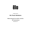
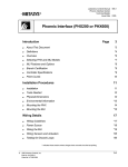
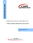
R.A.S.E.R. DX Operating Manual www.ellipticalmobilesolutions.com R.A.S.E.R. DX Operating Manual Table of Contents 1 2 3 4 5 Welcome to R.A.S.E.R. DX ……………………………………………………. 4 1.1 Read this first ……………………………………………………………………. 4 1.2 Manufacturer's Safety Information……………………………………………………… 4 1.3 1.2.1 Liability Disclaimer……………………………………………………………… 4 1.2.2 Safety symbols used in this manual…………………………………. 5 Safety Information for the Operation…………………………………………….. 6 1.4 Additional literature…………………………………………………………………………. 6 Warranty and Return………………………………………………………… 7 2.1 Overview……………………………………………………………………………… 7 2.2 Items and services not covered by this warranty……………………………… 7 2.3 To exercise this limited warranty………………………………………………….. 7 2.4 Limitations and exclusions……………………………………………………… 2.5 Return material authorization procedure………………………………………….. 8 7 R.A.S.E.R. DX Features…………………………………………………………. 9 3.1 Active suspension…………………………………………………………………… 9 3.2 Fire suppression……………………………………………………………………… 10 3.3 Cyberlock key system…………………………………………………………… 10 3.4 Power connectivity………………………………………………………………. 11 3.5 Environmental package…………………………………………………………. 11 3.6 Mission critical venting……………………………………………………………… 12 3.7 Interior lighting…………………………………………………………………… 13 Air Flow…………………………………………………………………………….. 14 4.1 Cooling system…………………………………………………………………… 14-15 4.2 Footprint and minimum clearances…………………………………………….. 16 4.3 Specifications and facility requirements ………………………………………. 17-19 R.A.S.E.R. DX Operations………………………………………………………. 20 5.1 5.2 5.3 5.4 5.5 Floor landing…………………………………………………………………….. A/C Temperature………............................................................................... Connecting A/C............................................................................................ 5.3.1 Adjusting thermostat....................................................................... 5.3.2 Condensation…………………………………………………………… 5.3.4 Blanking Plates……………………………………………………..…. Side Car ....................................................................................................... To lock and unlock the R.A.S.E.R. DX……….............................................. www.ellipticalmobilesolutions.com 20 20 21 21 22 22 23 24 R.A.S.E.R. DX Operating Manual 5.6 Air conditioner door.......................................................................................... 24 5.7 Closing and securing A/C panel ..........................................................;..... 25 5.8 A/C condensate pan.................................................................................... 25 5.9 Moving the R.A.S.E.R. DX.......................................................................... 26 5.10 Loading the R.A.S.E.R. DX.......................................................................... 6 27 Maintenance ................................................................................................... 28 6.1 A/C…………………. ..................................................................................... 28 6.2 Inlet filter…………........................................................................................ 28 6.2.1 29 Cleaning inlet filter………............................................................ 7 Notes…………................................................................................................. 30 8 R.A.S.E.R. DX A/C Manual ............................................................................ 31 8.1 Receiving the A/C. ......................................................................................... 31 8.2 Handling and testing the A/C………….……….. ............................................. 31-32 8.3 Dimensions………………………………………………………………….…….. 33 8.4 Installation………………….............................................................................. 34 8.5 Design data, model drawing………................................................................ 35 8.6 Fan and control valve connections ................................................................... 35 8.7 Schematic and Wire Diagrams.................................................................. 36 8.8 Principles of operation.... ........................................................................... 37 8.9 Maintenance .................................................................................................. 37-38 8.10 Trouble shooting............................................................................................ 39-42 8.11 Warranty…………………………………………………………………………… 42-43 8.12 Return and repair policy…………………………………………………………. 44-45 www.ellipticalmobilesolutions.com R.A.S.E.R. DX Operating Manual 1 Welcome to the R.A.S.E.R. DX 1.1 Read this first We would like you to get the most out of your R.A.S.E.R. DX. When you FIRST use the R.A.S.E.R. DX, you must know how to properly operate and care for it to avoid unsafe situations. PLEASE Read and understand this operator’s manual and ALL the safety instructions before operating the R.A.S.E.R. DX. Customer service is of the utmost importance to us at Elliptical Mobile Solutions. If you have any issues or concerns regarding your R.A.S.E.R. DX, please call our customer service department at 1-888-924-0547. 1.2 Manufacturer's Safety Information 1.2.1 Liability Disclaimer EMS accepts no liability for any errors in this documentation. To the maximum extent permissible by law, any liability for damage, direct or indirect, arising from the supply or use of this documentation is excluded. EMS retains the right to modify this document, including the liability disclaimer, at any time without notice and accepts no liability for any consequences of such alterations. 1.2.2 Safety symbols used in this manual Hazardous voltage! This symbol warns of hazardous voltage. Before commencing work on live sections of the equipment you should familiarize yourself with the dangers of high voltages and with the normal accident-prevention procedures. Attention! This symbol warns of danger. It indicates that you are in a situation that could be injurious to health. Before commencing work you should familiarize yourself with the normal accident-prevention procedures. www.ellipticalmobilesolutions.com R.A.S.E.R. DX Operating Manual .. Static discharge hazard! Static electricity can damage sensitive components in the system. To avoid such damage you should wear ESD armbands or maintain frequent bodily contact with a part of the metal enclosure. Danger of tipping over! The asymmetrical positioning of the cooling module poses a risk of the cabinet tipping over. The R.A.S.E.R. DX must always be adequately secured during transport. Important! Indicates important information in this manual. . ON / OFF: Please turn the Key Switch in the direction required. Plug / Unplug: Required step in maintenance procedures. www.ellipticalmobilesolutions.com R.A.S.E.R. DX Operating Manual 1.3 Safety Information for the Operator To prevent accidents which can cause injury to you, damage the unit or its contents: 1. ALL persons using the R.A.S.E.R. DX MUST read this operator’s manual. 2. ONLY trained personnel should be allowed to operate the R.A.S.E.R. DX 3. Disconnect ALL cabling before moving the unit. 4. DO NOT leave cables hanging outside through cable grommets. [See page ] 5. The air conditioner unit MUST be secured to enclosure with all ten (10) Allen screws before moving the unit with a pallet jack or fork lift. (See page 6. ONLY move the unit with a pallet jack or fork lift on smooth surfaces or ramps. 7. DO NOT move the unit diagonally up or down ramps and inclines. 8. The R.A.S.E.R. DX has a maximum load capacity of 1500 pounds (680 kg). DO NOT exceed the rated 1500-pound (680 kg) capacity. 9. ALWAYS load and unload the R.A.S.E.R. DX on a flat, level surface. . Fig. 1: Weight distribution in R.A.S.E.R. DX ALWAYS load the R.A.S.E.R. DX with the heaviest component on bottom to prevent tipping when moving it. [Fig. 1]. 1.4 Manufacturer's Safety Information Additional information can be found on our website at www.ellipticalmobilesolutions.com www.ellipticalmobilesolutions.com 6 R.A.S.E.R. DX Operating Manual 2 Warranty and Return 2.1 Overview Elliptical Mobile Solutions warrants this product against defects in manufacturing, materials, or workmanship for a period of twelve (12) months from the date shipped from the factory, covering parts, shipping, labor and service calls. Defective parts will be repaired or replaced with new or reconditioned parts at the company’s option. Service calls will be next business day 9am to 5pm local time within the 48 contiguous states, excluding national and locally observed holidays. See extended regional/international coverage supplement document. 2.2 Item and services NOT covered by this warranty 2.3 Defects caused by unauthorized work performed on the product. Part failure resulting from failure to maintain the product as specified in the manual. Product or part failures caused by unauthorized modification of the product. Unauthorized modification of this product voids this entire warranty. Any part, accessory, or modification – authorized or not – placed on this product which is not manufactured, supplied or installed by Elliptical Mobile Solutions. Any warranty or claim made by the reseller or agent contrary to, or in addition to, this warranty. This entire warranty is limited to the original consumer only and is not transferable. To exercise this limited warranty: Contact warranty support at 1-888-924-0547. Elliptical Mobile Solutions will repair or replace the defective part(s) at the company’s option IF the defect is a result of manufacturing, materials, or workmanship during the warranty period. 2.4 Warranty limitations and exclusions To the maximum extent permitted by applicable law, this limited warranty excludes any claim for incidental or consequential damages AND is in lieu of any implied or other warranties. Elliptical Mobile Solutions reserves the right to make changes to this warranty at any time without notice. www.ellipticalmobilesolutions.com 7 R.A.S.E.R. DX Operating Manual Consumer Name: Purchased From: Date Purchased: Model Number: 2.5 Serial Number: Return Material Authorization (RMA) procedure All returns require a Return Material Authorization (RMA) number for warranty or nonwarranty repair, damage or any other reason. IMPORTANT..returns without an RMA number will be refused and returned. Improper packaging may void Warranty. Micro Mobile Data Centers shipped lying down will void the warranty. Collect shipments will be refused. Please be ready to provide: Purchase Order Number & Date Product Description & Reason for Request Model Number & Serial Number Customer name and contact info (email, phone number and address) Shipping method Pack unit in a suitable packing for shipment, preferably the original packaging if available. If suitable packing is not available, arrange for packaging to be shipped to you. Unit must be returned in an upright position properly secured in a shipping crate. Clearly mark the RMA number on the container. Customer will pay all freight charges. Out of Warranty Repair: If your Micro Module Data Center is out of warranty and requires repair, simply call or email Elliptical Mobile Solutions Service at (480-924-0547) or ([email protected] ) for an RMA number. Customer Service will help you determine what repairs or parts are needed and, if possible, an estimate of the cost. After the unit is received and diagnosed, you will receive a ship estimate on the work and parts needed. The repairs and test process may uncover other issues for which you will be informed and given quotes for the work needed. www.ellipticalmobilesolutions.com 8 R.A.S.E.R. DX Operating Manual 3 R.A.S.E.R. DX Features The R.A.S.E.R. DX’s welded steel frame supports up to 1,500 pounds (680 kg) of electronic equipment. The steel inner frame mounted with elastomeric isolators conforms to an industry standard rack format – 19” wide by 36” deep (48 cm. wide by 90 cm. deep). All rack rails are fully adjustable for depth. The R.A.S.E.R. DX is available with a 41,000 BTU (12kw) air conditioner. Overall Length 75 in. (190.5 cm.) Overall Width 30 in. (76.2 cm.) Overall Height (empty) 83 in. (210.8 cm.) 19” wide x 36” deep 48.3 cm. wide x 91.4 cm. deep Inner Frame Weight (empty) 1400 lbs. (635 kg.) Equipment Capacity 1,500 lbs. (680 kg.) -40˚F to 130˚F* (17˚C to 49˚C) Operational Temperature (optimal) Total Cooling Capacity 12kw (AC) Air Conditioning Power 208-240 VAC 50/60hz Single Phase @ 27amps High Density Equipment Capacity 36U Low Density Equipment Capacity 6U Interior Lighting Power 100-250 VAC 50/60hz Single Phase @ 2 amps 3.1 Suspension Elastomeric material isolates and protects the inner frame from the effects of vibration and shock. These isolators are specially formulated to dampen the high-frequency vibrations from ground or air transport. www.ellipticalmobilesolutions.com 9 R.A.S.E.R. DX Operating Manual 3.2 Fire Suppression – Novec 1230 All of EMS’s products use the firetrace, fire suppression system. This system offers unique polymer lines. These lines melt at 200 degrees. This allows them to create a nozzle when connected to heat or direct flame.This nozzle then disperses Novec 230 which is a true dialetric. And as a dialetric it does not damage the equipment inside and requires no clean up. Please refer to the manufacturer’s FireTrace manual for more information regarding useage. Addition requirements for the room MAY be required depending on local code. The National Fire Protection Association’s Standard for the Protection of ElectronicComputer Data Processing Equipment, NFPA 75, contains information on safety monitoring equipment for computer rooms. . 3.3 Cyberlock® Key System For the ultimate in security, the Cyberlock® Key System contains many features that aren’t possible with a standard lock and key system. The lock installs without any wiring and does not contain a battery. A 3-volt lithium battery in the CyberKey® powers this system. This battery is easily replaced. Please refer to the Cyberlock® manual. Cyberlocks® do not utilize tumblers -- cannot be picked like a mechanical lock. Dirt and moisture will not interfere with the operation of the lock cylinder. Cyberlocks® resist forced rotation and tampering – they are designed to remain in the locked position. It is impossible to create a duplicate of a CyberKey®. Passwords are unique to each installation. Each CyberKey® may be assigned unique permissions – which lock that particular key will open, the time of day it can access the lock, and when (based on beginning and expiration dates). Multiple CyberKeys® may be programmed alike or differently. The CyberKey® records the lock ID, date and time that it accesses the R.A.S.E.R. DX while the Cyberlock® records the key ID, date and time. Each CyberKey® can store up to 3900 access events and each Cyberlock® stores up to 1100 access events. www.ellipticalmobilesolutions.com 10 R.A.S.E.R. DX Operating Manual Unauthorized attempts to open the Cyberlock® are also stored there. Please refer to the manufacturer’s Cyberlock® Key System Manual for more specific information regarding the programming and usage of this system. 3.4 Power Connectivity Customers can route their primary and secondary equipment power cords through three (3) 4-inch Brush Grommets located in the bottom of the side car or optional top egress [Fig. 2]. Power whips are to feed under the pallet and through the brush grommet. Keep plugs inside side car area when using the R.A.S.E.R. DX for an outdoor application. Fig. 2: Three 4-inch brush grommets 3.4 Environmental Package The R.A.S.E.R. DX comes with a standard NEMA 3R or optional NEMA 4 environmental package, (as described below) allowing it to operate indoors or outdoors. Type 3R: Enclosures constructed for either indoor or outdoor use to provide a degree of protection to personnel against access to hazardous parts; to provide a degree of protection of the equipment inside the enclosure against ingress of solid foreign objects (falling dirt); to provide a degree of protection with respect to harmful effects on the equipment due to the ingress of water (rain, sleet, snow); and that will be undamaged by the external formation of ice on the enclosure. Type 4: Enclosures constructed for either indoor or outdoor use to provide a degree of protection to personnel against access to hazardous parts; to provide a degree of protection of the equipment inside the enclosure against ingress of solid foreign objects (falling dirt and windblown dust); to provide a degree of protection with respect to harmful effects on the equipment due to the ingress of water (rain, sleet, snow, splashing water, and hose directed water); and that will be undamaged by the external formation of ice on the enclosure. www.ellipticalmobilesolutions.com 11 R.A.S.E.R. DX Operating Manual 3.6 Mission Critical Venting For redundancy, the R.A.S.E.R. DX offers optional Mission Critical Venting. In the event of a power failure, a high power fan will continue to keep the air circulating within the equipment. The louvers on the side will open drawing in cool ambient air and venting it out the top until backup power or a generator startup begins. High powered fan will continue to move air during datacenter power outage Mission Critical Venting Hot air from equipment Close up view ent ipm u q E ent pm i u Eq ent ipm Equ nt Cool Ambient Air me uip Eq Copyright Elliptical Mobile Solutions 2009 The size of the room, the temperature of the room, and the heat load inside the R.A.S.E.R. DX all affect the amount of back-up ventilation time available. The table below contains estimates of the time until the internal rack equipment reaches 95°F (with back-up ventilation running and RASER DX cooling off). www.ellipticalmobilesolutions.com 12 1 R.A.S.E.R. DX Operating Manual Room Volume (Cubic Feet) 6 kW Load 12 kW Load 1,200 2 minutes >1 minute 2,400 4 minutes 2.25 minutes 5,000 8 minutes 4.5 minutes 7,500 12 minutes 6 minutes 10,000 15 minutes 8 minutes NOTE - The following assumptions apply: 3.7 The temperature in the room is 75° F when back-up ventilation begins operating. No cooling is done by the building system during the back-up ventilation. If the building cooling system continues to run during backup ventilation, the time to reach 95°F will be longer. Interior Lighting Magnetic switches attached to the doors control the interior lighting. The rear lighting is switched by the rear side car door only. The lighting power supply [Fig. 3] accepts a standard c-13 computer power plug. The power supply will accept 100-250v AC 50/60 hz power. Fig. 3: Lighting power supply www.ellipticalmobilesolutions.com 13 R.A.S.E.R. DX Operating Manual 4. Air Flow 4.1 Cooling Description The R.A.S.E.R. DX is an air conditioning cooled enclosure. As with most HVAC systems there is an external open loop and an internal closed loop air stream. See fig 4. The internal closed loop air stream is routed under the equipment to the front face of the IT equipment. Utilizing a Zero Bypass air management plenum, the air is forced through the equipment. The hot air is then returned the HVAC unit to be cooled. The external open loop is where the heat inside the cabinet is removed. The air is pulled in on each side of the HVAC unit and blown out the back. A hot air out ducting kit is available. www.ellipticalmobilesolutions.com 14 R.A.S.E.R. DX Operating Manual Fig. 4: Airflow diagram The venting of the hot air produced by the HVAC unit must be taken into consideration when deciding enclosure placement. A distance of 18”on each side and behind the HVAC is required for proper airflow clearances. If the enclosures are being placed next to each other a distance of 30” is required unless our alternating pattern is used. See fig 5 and 6. When the enclosure is located outside no additional ducting is needed, only proper air pathway clearances. www.ellipticalmobilesolutions.com 15 R.A.S.E.R. DX Operating Manual 4.2 R.A.S.E.R. DX Footprint and Minimum Clearances Top View Side View DX Slides Back 18” Locking Slides Vibration and Shock Isolators www.ellipticalmobilesolutions.com 16 R.A.S.E.R. DX Operating Manual 4.3 R.A.S.E.R. DX Specifications & Facility Requirements Dimensions and Weights Table provides dimensions and weights of the R.A.S.E.R. DX system that is not populated. Unpackaged R.A.S.E.R. DX Crated R.A.S.E.R. DX Height Width Depth Weight 83” 30” 75” 1,050 LBS(a) 93” 38” 83” 1,400 LBS(b) a. This weight represents a fully assembled R.A.S.E.R. DX before any components are installed. b. This weight represents the packaged weight of the R.A.S.E.R. DX, along with all packaging materials such as cartons and skid. Fig. 5: Mono directional placement Fig. 6: Alternating placement The R.A.S.E.R.DX can also be used indoors utilizing one of several different ventilation options. www.ellipticalmobilesolutions.com 17 R.A.S.E.R. DX Operating Manual General room venting- The open loop air volume is 2300cfm per R.A.S.E.R.DX. A room can use an exhaust vent appropriately sized to move the volume of air equal to the open loop. An air intake for the room must also be sized to bring in that volume of air. The air intake can be from outside ambient air. If ambient air is used, the temperature in the room will be above ambient. If the air intake is conditioned from inside the building, then the room temperature will be above the building air temperature. When using inside conditioned air, remember the HVAC will pull 2300cfm of air out of the building per unit. See fig 7. Then the room temperature will be above the building air temperature. When using inside conditioned air, remember the HVAC will pull 2300cfm of air out of the building per unit. See fig 7. Fig. 7: General room venting Hot air out ducting- A ducting shroud can be added to the hot air out side of the open loop. This would not allow the hot air to mix with room air. When direct ducting the hot side, a booster fan would be required if the ducting is more than 10’ in length. A room air intake would still be required to satisfy the open loop air volume. The room intake can be from outside or inside the building. The hot air out ducting will allow the room to be either same as the outside ambient or the building inside temperature. See fig 8. www.ellipticalmobilesolutions.com 18 R.A.S.E.R. DX Operating Manual Fig. 8: Hot air out ducting Mixed air environment- When the room containing the R.A.S.E.R.DX requires comfort cooling without removing the building air, the open loop would need ducting for both intake and exhaust. This would allow the containing room to have comfort cooling without removing inside air or adding load to building HVAC. If ducting for intake and exhaust are greater than 10’ then a booster fan is required. See fig 8. Fig 9: Mixed air environment NOTE- IF external intake air is being filtered, the exhaust fan must be oversized to account filter resistance. The volume of air leaving the room must be 2300cfm per unit. www.ellipticalmobilesolutions.com 19 R.A.S.E.R. DX Operating Manual 5. Operating the R.A.S.E.R. DX 5.1 Floor Loading The R.A.S.E.R.DX has an empty weight of 1400lbs and can support up to 1500lbs of IT equipment. The actual weight of the installed equipment plus the enclosure weight must be calculated to determine the total weight. The total weight is then divided by the 13.5 sqft the enclosure occupies. This number will give the pounds per square inch created by the whole system. Please verify with your facilities personal or a structural engineer to confirm the intended location can support the combined weight. 5.2 Air Conditioner Temperature The air temperature within the R.A.S.E.R. DX can be controlled by a 12kw air conditioner unit (A/C). This unit cools any electronic equipment inside the R.A.S.E.R. DX regardless of the temperature outside. The BTU cooling capacity diminishes as the outside temperature rises -- see Air Conditioner Manual for ambient temperature graph. This air conditioner operates with 208v-240v AC 50/60hz single phase power. A 35 amp breaker and a 50amp California standard (Hubbell CS8264C) plug is required. Please refer to the supplementary air conditioner manual for operating instructions and additional information. Slides under the air conditioner enable you to pull it away from the enclosure. www.ellipticalmobilesolutions.com 20 R.A.S.E.R. DX Operating Manual 5.3 To Connect the Air Conditioner: 1. Feed 50 amp power plug whip under pallet from outside, then up through brush grommet. [Fig. 10] 2. Connect whip to A/C inlet plug. Keep plugs inside sidecar for security or any outdoor applications. [Fig. 11] 3. Plug cord into wall OR energize whip to start air conditioner. Fig. 10: A/C power egress Fig. 11: Power cord connection 5.3.1 To Adjust Thermostat: 1. Remove fourteen (14) Phillips head screws from back of A/C unit [Fig. 12] 2. Remove access panel. 3. Adjust thermostat between 70 ºF (21ºC) and 100 ºF (38ºC) as needed. [Fig. 13] 4. Replace access panel. 5. Install all fourteen (14) screws back into their holes. www.ellipticalmobilesolutions.com 21 R.A.S.E.R. DX Operating Manual DO NOT OVER-TIGHTEN SCREWS. Fig. 12: Arrows point to 14 screws Fig. 13: Arrow points to thermostat control 5.3.2 Condensation The R.A.S.E.R. DX utilizes a standard HVAC system which will condense the moisture inside the enclosure. The moisture (water) is condensed on the evaporator and then collected in the drip pan. The drip pan volume can support the maximum amount of humidity within the enclosure provided the doors are kept closed during operation. If the doors are left open the HVAC system will extract more moisture than the drip pan can contain. Condensation can form on the enclosure depending on certain thermal loads and/or environmental conditions. In high humidity environments the cold air plenum insulation option may be required to prevent condensation from forming on the underside of enclosure and front door. Condensation can also form in these locations if the temperature set point of the HVAC is set below ambient wet bulb temperature. The ambient wet bulb is usually well below the desired internal temperature. Raise the thermostat set point to 75F or higher to correct the problem. 5.3.3 Blanking Plates The R.A.S.E.R. DX uses a high pressure cold plenum to maximize air delivery to the IT equipment. The high pressure plenum is created by our zero by-pass sealing system. For the system to work properly all RU spaces within the rack must be filled with www.ellipticalmobilesolutions.com 22 R.A.S.E.R. DX Operating Manual equipment or blanking plates. If blanking plates are not used, the air will take the path of least resistance. The air will not flow through the IT equipment but through the opening leading back to the closed loop return. This will cause the HVAC to operate at lesser efficiency and reduced capacity. See fig 9. Note: Blanking plates must be used in all open RU spaces to avoid excess condensation. 5.4 Side Car The R.A.S.E.R. DX has a low heat density area for patch and network equipment. [Fig. 10] The side car has (3) 2U sections installed vertically. Use any 19 inch form factor patch panel or switch equipment that attaches by standard square-hole inserts. Push cabling up through the brush grommets in the front of the side car area or through optional top egress. [See page 8] DO NOT load heavy equipment into sidecar – especially NOT a power conditioner or UPS (uninterruptable power supply). www.ellipticalmobilesolutions.com 23 R.A.S.E.R. DX Operating Manual 5.5 To Unlock and Lock the R.A.S.E.R. DX To open the R.A.S.E.R. DX enclosure: 1. Insert key or Cyberkey® (optional) into the lock assembly. 2. Lift door handle [Fig. 14] ninety degrees (90º) to release latch. To latch doors: 1. Lift door handle to the lifted open position. Fig. 14: Lifted handle (with CyberKey) 2. Push door closed. 3. Push door handle down to engage latches to the frame. 4. Once closed and latched, engage lock. 5.6 Air Conditioning Door To open A/C panel: 1. Remove (10) Allen head screws from A/C panel. There are 5) screws on each side of the air conditioner. [Fig. 15] 2. Press down on yellow locking brake levers [Fig. 16] on slides under air conditioning (A/C) unit. 3. Pull A/C unit back SLOWLY to access back of rack. CAUTION: A/C UNIT is heavy. Slide it carefully away from the enclosure and back into place. Fig. 15: Arrows point to screws www.ellipticalmobilesolutions.com 24 R.A.S.E.R. DX Operating Manual 5.7 To close and secure A/C panel: 1. Lift up on yellow locking brake levers located on slides underneath A/C unit. 2. Push A/C unit forward until slides lock closed. 3. Install (10) Allen head screws into A/C panel. Fig. 16: Yellow slide releases 5.8 Air Conditioner Condensate Pan When the doors are closed, any humidity will be trapped inside of the enclosure. The air conditioner will condense the water vapor, which will collect in the drip pan. The water in the drip pan will then evaporate into the ambient surroundings. If the R.A.S.E.R. DX doors are left open in a high humidity environment, more water may condense than the drip pan can hold. 1. Open A/C panel. [See page 13] 2. Remove two (2) swing nut screws from the drip pan. [Fig. 17] 3. Remove drip pan and dump water in drain. 4. Reinstall drip pan and screws. Figure 17: Arrows point to screws www.ellipticalmobilesolutions.com 25 R.A.S.E.R. DX Operating Manual 5.9 Moving the R.A.S.E.R. DX: The R.A.S.E.R. DX is designed to support 1500lbs of dynamic load. Equipment up to that weight can be installed and the enclosure moved by a pallet jack or forklift without damaging the equipment. An industry standard 27” wide pallet jack is required to move the enclosure from side, front or back. 1. Disconnect power whips, network cables and any other cabling that has been pulled through the grommets. [See Equipment Power page 8 2. Remove all cabling from the pallet/skid area. 3. Install all ten (10) Allen head screws into A/C panel 4. Insert forklift tines or pallet jack below R.A.S.E.R. from any side. [Fig. 18] 5. Move R.A.S.E.R. DX slowly and carefully. 6. Secure R.A.S.E.R. DX to the vehicle or trailer that will transport it with securing bars or ratchet straps. Ratchet straps should be rated for 3000 lbs. or greater. Fig. 18: Forklift or pallet jack placement through R.A.S.E.R. DX pallet www.ellipticalmobilesolutions.com 26 R.A.S.E.R. DX Operating Manual 5.10 Loading the R.A.S.E.R. DX Load the R.A.S.E.R. DX with the heaviest equipment mounted at the bottom of the 19 inch rack and lightest equipment on the top rack. [Fig. 19] Fig. 19: Weight distribution in R.A.S.E.R. DX www.ellipticalmobilesolutions.com 27 R.A.S.E.R. DX Operating Manual 6. Maintenance A properly-maintained R.A.S.E.R. DX will give you years of safe and dependable service. We recommend the following maintenance program: ONLY Authorized Service Technicians should inspect or service the R.A.S.E.R. DX. 6.1 Air Conditioner The compressor, condenser and evaporator blowers require no maintenance. 6.2 Inlet Filter Proper maintenance of the inlet filter will assure normal operation of the A/C. If filter maintenance is delayed or ignored, the maximum ambient temperatures under which the unit is designed to operate will be decreased. We cannot recommend any interval for cleaning the filter because of: Local conditions, especially the amount of airborne dust/dirt particles in the area. The particular operating duty cycles of each unit’s air conditioner. Accidents or disasters which cause excessive water or room damage. Basic Steps: 1. Check filter regularly for a thin layer of dust and lint. 2. Remove dusty filter and turn it over, then install it again. 3. Clean filter as instructed below when both sides are dusty. www.ellipticalmobilesolutions.com 28 R.A.S.E.R. DX Operating Manual 6.2.1 Cleaning Instructions: 1. Remove screw at top center of filter. Lift out filter. [Fig. 20] 2. Flush the filter with warm water from the exhaust side to the intake side. 3. DO NOT use caustic cleaning solutions like bleaches or solvents. 4. Allow filter to drain after flushing it. Place it with a corner down to assure complete drainage. 5. Drain or spray filters with RP Super Filter Coat® adhesive 6. Spray filter from both sides to maximize the filter’s absorption of this required adhesive. 7. DO NOT install the filter without recoating it. Figure 20: A/C filter in place www.ellipticalmobilesolutions.com 29 R.A.S.E.R. DX Operating Manual 7. Notes www.ellipticalmobilesolutions.com 30 R.A.S.E.R. DX Operating Manual 8 R.A.S.E.R. DX A/C Manual NOTE: Some of the information in this manual may not apply if a special unit was ordered. If additional drawings for a special unit are necessary, they have been inserted. Contact Elliptical Mobile Solutions if further information is required. 8.1 Receiving the Air Conditioner Inspect the air conditioner. Check for concealed damage that may have occurred during shipment. Look for dents, scratches, loose assemblies, evidence of oil, etc. Damage evident upon receipt should be noted on the freight bill. Damage should be brought to the attention of the delivering carrier within 15 days of delivery. Save the packing material and request an inspection. Then file a claim with the delivering carrier. Elliptical Mobile Solution cannot accept responsibility for freight damages; however, we will assist you in any way possible. Please call tech support at (480) 924-0547. 8.2 Handling the Air Conditioner Be certain your R.A.S.E.R. DX is kept upright at all times. Never attempt to operate the air conditioner while it is horizontal or on its side, back or front. The refrigeration compressor is filled with lubricating oil. Running the compressor without oil in the lower part of the housing will cause permanent damage to the air conditioner. This also voids the warranty. TEST FOR FUNCTIONALITY BEFORE LOADING EQUIPMENT IN THE ENCLOSURE. Refer to nameplate for proper electrical current requirements, then wire unit to a properly grounded power supply. Minimum circuit ampacity should be at least 125% of the amperage shown in the design data section for the appropriate model. No other equipment should be connected to this circuit to prevent overloading. Immediately after applying power the evaporator blower (enclosure air) should start running. Operate the air conditioner with the compressor running for five (5) to ten (10) minutes. Condenser air temperatures should be warmer than normal room temperatures within a few minutes after the condenser air blower starts. www.ellipticalmobilesolutions.com 31 R.A.S.E.R. DX Operating Manual The compressor is provided with automatic reset thermal overload protection. The switch operates when the compressor overheats due to a clogged or dirty condenser coil or if ambient air temperatures exceed nameplate rating or if enclosure dissipated heat loads exceed the rated capacity of the air conditioner. The thermal overload switch will actuate and stop compressor operation. The blowers will continue to operate and the compressor will restart after it has cooled to within the thermal overload cut-in temperature setting. www.ellipticalmobilesolutions.com 32 R.A.S.E.R. DX Operating Manual 8.3 Dimensions www.ellipticalmobilesolutions.com 33 R.A.S.E.R. DX Operating Manual 8.4 Installation 1. Inspect air conditioner. Verify functionality. 2. Using the mounting gasket kit provided with the unit, install gaskets to the air conditioner as shown in Figure 1. 3. Mount air conditioner on enclosure taking care not to damage the mounting gasket. The mounting gasket is the seal between the air conditioner and the enclosure. Avoid dragging the air conditioner on the enclosure with the mounting gasket attached as this could cause rips or tears in the gasket and risk losing the water tight seal. 4. Allow unit to remain upright for a minimum of five (5) minutes before starting. Caution: Air conditioner must be in upright position during operation. 5. Refer to the nameplate for electrical requirements. Wire the unit to a properly grounded power supply. Electrical circuit should be fused with slow blow or HACR circuit breaker. 6. The air conditioner requires a remote mounted thermostat and has an alarm feature. Wire the thermostat and alarm outputs to the appropriate terminals the 24VAC terminal strip (note locations on the wiring diagram). www.ellipticalmobilesolutions.com 34 R.A.S.E.R. DX Operating Manual 8.5 8.6 Design Data, Model Drawing Fan and Control Valve Connections www.ellipticalmobilesolutions.com 35 R.A.S.E.R. DX Operating Manual 8.7 Schematic and Wire Diagrams www.ellipticalmobilesolutions.com 36 R.A.S.E.R. DX Operating Manual 8.8 Principles of Operation If electrical power to the air conditioner is interrupted and reapplied immediately,(within 3 to 5 seconds), the compressor may not restart due to the high back pressure of the compressor. It takes a minimum of one (1) minute after shutdown for the compressor suction and discharge pressures to equalize in order for the air conditioner to restart. Operating the air conditioner below the minimum ambient temperature or above the maximum ambient temperatures indicated on the nameplate voids all warranties. It is recommended that the warranty section of this manual be read in order to familiarize yourself with parameters of restricted operation. The moisture that the enclosure air can contain is limited. If moisture flows from the drain tube continuously, this only can mean that ambient air is entering the enclosure. Be aware that frequent opening of the enclosure’s door admits humid air that the air conditioner must then dehumidify. 8.9 Maintenance Compressor The compressor requires no maintenance. It is hermetically sealed, properly lubricated at the factory and should provide years of satisfactory operating service. Should the refrigerant charge be lost, recharging ports (access fittings) on the suction and discharge sides of the compressor are provided for recharging and/or checking suction and discharge pressures. Under no circumstances should the access fitting covers be loosened, removed or tampered with. Breaking of seals on compressor access fittings during warranty period will void warranty on hermetic system. Recharging ports are provided for the ease and convenience of reputable refrigeration repair service personnel for recharging the air conditioner. www.ellipticalmobilesolutions.com 37 R.A.S.E.R. DX Operating Manual Condenser and Evaporator Air Movers Blower and impeller motors require no maintenance. All bearings, shafts, etc. are lubricated during manufacturing for the life of the motor. If the condenser blower motor (ambient blower) should fail, it is not necessary to remove the air conditioner from the cabinet or enclosure to replace the blower. The condenser blower is mounted on its own bulkhead and is easily accessible by removing the front cover. Caution: Operation of the air conditioner in areas containing airborne caustics or chemicals can rapidly deteriorate filters, condenser coils, blowers and motors, etc. Contact McLean Cooling Technology for special recommendations. Refrigerant Loss Each air conditioner is thoroughly tested prior to leaving the factory to insure against refrigeration leaks. Shipping damage or microscopic leaks not found with sensitive electronic refrigerant leak detection equipment during manufacture may require repair or recharging of the system. This work should only be performed by qualified professionals, generally available through a local, reputable air conditioning repair or service company. Refer to the data on the nameplate, which specifies the type of refrigerant and the charge size in ounces. Before recharging, make sure there are no leaks and that the system has been properly evacuated into a deep vacuum. www.ellipticalmobilesolutions.com 38 R.A.S.E.R. DX Operating Manual 8.10 TROUBLE SHOOTING Basic Air Conditioning Trouble Shooting Check List 1. Check manufacturer’s nameplate located on the unit for correct power supply. 2. Turn the power to the unit on. The evaporator (Enclosure or “COLD” air) blower should come on. Is there airflow? 3. YES, proceed to step # 3. NO, possible: Open motor winding Stuck blower motor Obstructed wheels/blades Check thermostat setting? Adjust thermostat to the lowest setting. This should turn the condenser blower and the compressor on. Did condenser blower and compressor come on when the thermostat was turned on? YES, proceed to step #4. NO, possible: Defective thermostat 1. Are both blowers and the compressor running? If not the unit will not cool properly. 2. Check condenser (Ambient or “HOT” air) blower for airflow. Is there airflow? YES, proceed to step # 6. NO, possible: Defective thermostat Open motor winding Stuck blower motor Obstructed wheels/blades www.ellipticalmobilesolutions.com 39 R.A.S.E.R. DX Operating Manual 3. Carefully check the compressor for operation - motor should cause slight vibration, and the outer case of the compressor should be warm. YES, wait 5 minutes, then proceed to step #7. NO, possible: Defective thermostat Defective capacitor Defective overload Defective relay 7. Are both blowers and the compressor running? If not the unit will not cool properly. 8. Check condenser (Ambient or “HOT” air) blower for airflow. Is there airflow? YES, proceed to step # 6. NO, possible: Defective thermostat Open motor winding Stuck blower motor Obstructed wheels/blades 9. Carefully check the compressor for operation - motor should cause slight vibration, and the outer case of the compressor should be warm. YES, wait 5 minutes, then proceed to step #7. www.ellipticalmobilesolutions.com 40 R.A.S.E.R. DX Operating Manual NO, possible: Defective thermostat Defective capacitor Defective overload Defective relay Make sure the coils are clean. Then check evaporator “air in” and “air out” temperatures. If the temperatures are the same: Possible loss of refrigerant Possible bad valves in the compressor To check for a bad thermostat. Turn power to the unit off. Remove control box cover, place both thermostat wires onto one terminal (replace control box cover for safety). This will pass the switch in the thermostat. Turn the power on. If both blowers and the compressor come on, the thermostat needs to be replaced. Symptoms and Possible Causes: Unit won’t cool Clogged fins on coil(s) Dirty filters Blowers/fans not running Compressor not running Compressor runs, but has bad valves Loss of refrigerant Compressor tries to start but won’t run * Low line voltage at start. Should be +/-10% rated voltage Compressor motor stuck Bad contactor Bad overload switch Bad run/start capacitor www.ellipticalmobilesolutions.com 41 R.A.S.E.R. DX Operating Manual Unit blows breakers Under sized breaker/fuse or not time delayed Short in system Getting water in enclosure Drain plugged Drain tube kinked Enclosure not sealed (allowing humidity in) Mounting gasket damaged For additional technical information contact Elliptical Mobile Solutions at (480) 924-0547. 8.11 Warranty Elliptical Mobile Solutions (EMS) warrants that the Goods will be free from defects in material and workmanship for a period of one (1) year from the date of shipment by EMS subject to the following conditions and exclusions: A. Conditions. All Goods must be installed and operated according to the following specifications: Maximum voltage variation no greater than plus or minus 10% of nameplate nominal rating; Maximum frequency variation no greater than plus or minus 3 Hz. of nameplate nominal rating; Must not exceed minimum and maximum stated temperatures on the nameplate; Must not exceed (BTU/Hr) rating, including any heat sink as indicated on the nameplate; Refrigerant bearing Goods must not be restarted for a period of one (1) minute after intentional or accidental shut-off; The filters (if applicable) must be cleaned regularly; www.ellipticalmobilesolutions.com 42 R.A.S.E.R. DX Operating Manual The Goods and any parts thereof must not be modified, unless prior written authorization is received from EMS; and All Goods must be installed and grounded in accordance with all relevant electrical and safety codes, as well as the National Electric Code and OSHA rules and regulations. All Goods must be installed in a stationery application, free of vibration. A violation of any one of these conditions shall render the warranty hereunder void and of no effect. B. Exclusions. This warranty shall be void if product is misapplied in any way or: Buyer specified product is inappropriate for system or environment it is operating in. Product modified in any way without prior written authorization from EMS. Removal or modification of EMS label affixed to product without written EMS approval. Elliptical Mobile Solutions must be notified of a claim in writing not later than fourteen (14) days from the date when Buyer has become aware of such occurrence, or where the defect is such that it may cause damage, immediately, such notice containing a description of how the defect manifests itself. Failure to provide such prompt notice to EMS shall result in forfeiture of Buyer’s rights under this warranty. In the event of a warranty claim, Buyer is to return defective goods to EMS in accordance with EMS Return Policy. Warranty period for repaired goods remains at 1 year from shipment of original goods. EMS’s sole obligation to Buyer under this warranty will be, at EMS’s option: Repair or replace products or parts found to be defective in material or workmanship. Issue credit for the purchase price paid by Buyer relating to such defective Goods or part. www.ellipticalmobilesolutions.com 43 R.A.S.E.R. DX Operating Manual THIS WARRANTY CONSTITUTES THE ENTIRE WARRANTY WITH RESPECT TO THE GOODS AND IS IN LIEU OF ALL OTHER WARRANTIES, EXPRESSED OR IMPLIED, INCLUDING ANY IMPLIED WARRANTY OF MERCHANTABILITY AND IMPLIED WARRANTY OF FITNESS FOR A PARTICULAR PURPOSE. 8.12 RETURN & REPAIR POLICY EMS products that: (i) are made to order, (ii)have been modified by Buyer , (ii) have special finishes, or (iv) are determined by EMS to constitute “custom” products that cannot be returned to stock or resold to other Buyers, will not be accepted for return by EMS. All returns require a Return Material Authorization number (RMA #), regardless of reason for return, whether it be for warranty or out of warranty repair. Returns without an RMA # will be refused by our Receiving Department. An RMA # is valid for 60 days. A. An RMA # will be issued by our Repair Department at 465 E. Chilton, Chandler, AZ. 85225. Buyer should have following information available at time of RMA request: 1. Complete Model Number, Serial Number and description of damaged unit being returned. 2. Original Buyer Purchase Order number and date product was received by Buyer. 3. Quantity to be returned and a brief description of failure for each unit, if different. 4. Contact information of Buyer that must include: name of company, billing and shipping address, phone, number, fax number, freight carrier and the name and phone number of a Buyer contact who can elaborate on the claimed defect in detail. 5. Buyer must provide a Repair Purchase Order number for both warranty and out of warranty repairs. The PO will not exceed 50% of a new unit. Buyer will be notified of repair charges that exceed approved PO amount. B. All returns must be securely packed, using original cartons if possible. All returns must have the RMA number visible on the outside of the carton. EMS is not responsible for material damaged in transit. Any refrigerant-bearing Goods must be shipped upright for return. C. Shipping cost for all non-warranty repairs is the responsibility of the sender and must be shipped prepaid. Shipping costs for all warranty related repairs will be covered by EMS provided the goods are returned using an EMS approved carrier. If www.ellipticalmobilesolutions.com 44 R.A.S.E.R. DX Operating Manual after diagnoses the product is determined by EMS not be covered under warranty, Buyer will be responsible for all shipping charges and will be billed accordingly. D. Non-warranty repairs are subject to a $75 minimum analysis fee. Analysis fee will be waived if Buyer approves repair work. If approval is not received within 30 days, material will be scrapped and all shipping expenses and corresponding analysis fees will be billed to Buyer. E. At Buyer’s request, Failure Analysis can be provided by EMS for warrantable goods at no charge. Failure analysis for non-warranty repairs are subject to a $100 per hour Engineering charge plus any other incurred testing costs. F. Credit for accepted returns shall be at the original selling price or the current selling price, whichever is lower, less the restocking charge indicated as follows: 1. 2. 3. 4. Within 60 days of invoice date - 20% of applicable selling price. Within 61-120 days of invoice date - 30% of applicable selling price. Within 121-180 days of invoice date - 40% of applicable selling price. Beyond 180 days - subject to individual review by EMS. If product being returned for credit requires repair or modification, the cost of any labor or material necessary to bring product into saleable condition will be deducted from credit. Buyer may not take credit against returns without prior written EMS approval. LIMITATION OF LIABILITY. EMS WILL NOT BE LIABLE UNDER ANY CIRCUMSTANCES FOR ANY INCIDENTAL, CONSEQUENTIAL OR SPECIAL DAMAGES, INCLUDING WITHOUT LIMITATION ANY LOST PROFITS OR LABOR COSTS, ARISING FROM THE SALE, USE OR INSTALLATION OF THE GOODS, FROM THE GOODS BEING INCORPORATED INTO OR BECOMING A COMPONENT OF ANOTHER PRODUCT, FROM ANY BREACH OF THIS AGREEMENT OR FROM ANY OTHER CAUSE WHATSOEVER, WHETHER BASED ON WARRANTY (EXPRESSED OR IMPLIED) OR OTHERWISE BASED ON CONTRACT, OR ON TORT OR OTHER THEORY OF LIABILITY, AND REGARDLESS OF ANY ADVICE OR REPRESENTATIONS THAT MAY HAVE BEEN RENDERED BY MCLEAN CONCERNING THE SALE, USE OR INSTALLATION OF THE GOODS . www.ellipticalmobilesolutions.com 45 Elliptical Mobile Solutions 465 E. Chilton Drive Suite #1 Chandler, Arizona 85225 Telephone: 480.924.0547 Fax: 480-924-0628 www.ellipticalmobilesolutions.com [email protected]