1
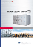
Leader in Electrics & Automation
SOLUTION 2000
Power Transmission & Distribution
Being Created by Diversified Industrial
Electricity Technology
Stabilized Power Supply and Maximization of Energy Efficiency
Where there is industry and electricity,
LS Industrial Systems always stands by your side.
2
SOLUTION 2000
The modular designed and type tested L. V Motor Control Center type SOLUTION 2000
satisfies the ever-increasing demand for high performance, high reliability,
safe operation and versatility required in industrial facilities.
福 Single and/or double (back to back) front construction.
福 Variable width wire way up to 400 mm with protection against accidental touch.
福 Combination of fixed and withdrawable units within the same cubicle.
福 3 ratings of plug-in contacts, 250A, 400A and 600A.
福 Fully insulated riser busbar front barrier assembly.
福 Protection against accidental touch of energized parts (IP20) without the need of automatic shutters.
福 Accessible from front to the compartment for the modules and cabling way.
福 Easy and simple rearrangement of module according to the operational requirements
without danger and switching-off the switchboard.
福 Can be equipped with up to 13 basic modules for motor control and 26 modules for
MCCB up to 100A rating.
SOLUTION 2000
3
TECHNICAL DATA
Standard
Type tested LV switchgear and controlgear assembly(TTA)
IEC 439-1
BS EN 60 439-1
AS 3439-1
Other national codes on request
Rated voltage
600V AC
Rated frequency
50/60Hz
Rated current
Main busbar
(3/4poles)
Vertical busbar
(3/4poles)
Rated short time withstand current(1s) Up to 80kA
Peak withstand current
Up to 176kA
Rated current
1000A, 1500A
Rated short time withstand current(1s) Up to 80kA
Peak withstand current
4
Up to 5000A (above 3000A double busbar)
Up to 176kA
Vertical control bar
Rated current
(2poles, up to 4poles)
80A at 380V
Arcing due to internal fault
Tested according to the AS 3439-1, appendix EE
Degree of protection
IP 40 for casing
IP 20 for compartment
Overall dimension
Height : 2300mm/ 2200mm
Width : 1000mm/ 900mm
Depth : 650mm / 1000mm(Duplex)
Thickness of material
Frame : 2.3mm
Door / Cover : 1.6mm (2.3mm as option)
Top and side plate : 1.6mm
Coating
Frame : LH-AH086-1 / Dark blue
Door/Cover : LH-RANTONE 420C / Light Yellow
Unit and others : hot dip galvanized steel
Wiring
Main : KIV 3.5mm2 as a minimum with black color
Control : KIV 1.25mm2
Name plate
Material : Acrylic
Letter : Gothic, Black
Background : White
SOLUTION 2000
MAIN BUSBAR
Main busbars are mounted at the upper and/or middle part of the cubicle.
Main busbar compartment is structurally isolated from unit compartment and cable way to
ensure safety.
VERTICAL BUSBAR
The vertical riser covered with arc proof is in the rear of module compartment.
The plug-in openings finger proof can be covered with automatic shutters as option.
MAIN BUSBAR SIZE (mm2)
A
Phase (A,B,C)
Neutral (N)
Earth (PE)
1000
75"10
40"10
40"10
1600
100"10
40"10
40"10
2000
2-75"10
75"10
50"10
2500
2-100"10
75"10
50"10
3150
2"(2-75"10)
2-50"10
50"10
4000
2"(2-100"10)
2-75"10
50"10
5000
2"(2-100"10)
2-75"10
50"10
VERTICAL BUSBAR SIZE (mm2)
A
Phase (A,B,C)
Neutral (N)
Earth (PE)
1000
72"6
40"6
40"6
1500
72"6+40"6
40"6
40"6
Main and vertical busbar compartment
SOLUTION 2000
5
UNIT
The height of drawable unit ranges from minimim 150mm to maximum 1050mm. The height is
increased by 150mm pitches. MCCB, electro-magnetic switches, motor protection relay, auxiliary
relays, timer, CT, ZCT, and fuses are placed at the point of unit while main circuit s draw-out plug and
control power plug, safety shutter opening guide are situated in the rear. Main circuit s secondary
draw-out plug and control plug are installed on the right side of unit.
Internal view
6
SOLUTION 2000
View into the cable compartment
View into
Service position
Test position
Draw-out position
Control and indication
Operation and indication elements are mounted
on the front plate of the unit
UNIT POSITION
SERVICE POSITION
Main circuit s primary and secondary draw-out
plugs, control power plug, control circuit
draw-out connector are connected to the power
source and load side components while the
unit locking device is in the locked position.
If locking is not effected securely, the unit might
have been positioned incorrectly.
TEST POSITION
Only control power plug and control circuit
draw-out connector are connected to the control
power source for the test operation. In this
position, all output control signals can be
checked through the control circuit connector.
DRAW-OUT POSITION
Main circuit s primary and secondary draw-out
plugs, control power plug, control circuit drawout connector are disconnected in this position.
The unit can be completely drawn-out from the
cubicle.
the unit compartment
Vertical busbar
Power plug for line side
Neutral busbar
Power plug for neutral
Fixed-power plug for load side
Movable power plug for load side
Control power busbar
Control power plug
Plug for control circuit
Socket for control circuit
Draw-out unit
SOLUTION 2000
7
STARTER ARRANGEMENT
3
6
1
4
5
2
7
1 Module base plate
2 Position locking device
3 Power plug (line side)
4 Power plug (load side)
5 24-pole control plug, connected in cable compartment
6 4-pole control power plug, connected to the control busbars
7 Cover for operation and indication
8
SOLUTION 2000
VIEW OF FRONT COVER
3
1
4
2
1 MCCB operating handle (Pad lockable in OFF-position)
2 Position locking device
3 Operation and indication plate
4 Draw-out handle
SOLUTION 2000
9
OVERALL VIEW
10
SOLUTION 2000
STRUCTURE
29
28
27
13
5
8
17
26
14
10
18
9
30
19
11
23
12
20
22
24
25
21
4
1
6
15
7
2
16
3
1
2
3
4
5
6
7
8
9
10
Basic frame
Bottom plate
Channel base
Cable compartment partition
Upper front cover plate
Lower front cover plate
Door for cable compartment
Main busbars
Vertical busbars
Vertical busbar clamp
11
12
13
14
15
16
17
18
19
20
Partition plate
Door
Arc proof barrier
Finger proof barrier
Plug for control circuit
Socket for control circuit
Power plug for line side
Power plug for neutral
Power plug for load side(600A)
Power plug for load side(250A)
21
22
23
24
25
26
27
28
29
30
Power plug for load side(125A)
Sleeve for cable protection
Module
Front cover
Draw-out handle
Insulator power busbar
Control power busbar
Top plate
Lifting lug
Safety shutter
SOLUTION 2000
11
STANDARD SPECIFICATION CODE
Vertical Busbar : 10=1000A 15=1500A
Main Busbar : 10=1000A, 16=1600A, 20=2000A
25=2500A, 30=3000A, 40=4000A
D=Double Front Type, S=Single Front Type
10=Cubicle Width (1000mm), 09=Cubicle Width (900mm)
SOLUTION 2000 MCC
DOUBLE FRONT TYPE
FRONT VIEW
12
SOLUTION 2000
BASE PLAN
SINGLE FRONT TYPE
FRONT VIEW
BASE PLAN
SOLUTION 2000
13
BASIC INSTALLATION DRAWING OF SOLUTION 2000 MCC
FRONT VIEW
SIDE VIEW
FIXED BY WELDING
FIXED BY BOLTS
DOUBLE FRONT TYPE
PLANE VIEW OF BOTTOM
SINGLE FRONT TYPE
PLANE VIEW OF BOTTOM
NOTE
1. A side plate is installed at the end of the line-up.
2. The installation of MCC having bottom cable entries requires foundation with an opening of a cable duct.
3. The horizontal tolerance of the level should not exceed ±1mm over length of 1 meter.
4. The MCC can be welded or screwed to the foundation frame.
5. The maximun number of cubicles for transportation is 2.
14
SOLUTION 2000
SOLUTION 2000
15
0.2
0.4/0.54
0.75
1.1
1.5
2.2
3.7
5.5
7.5
11
15
18.5
22
30
37
45/55
75
0.2
0.4/0.54
0.75
1.1
1.5
2.2
3.7
5.5
7.5
11
15
18.5
22
30
37
45
55
75
90/110
125
150
59~67
70~80
89~108
117~134
141~196
195~223
235~268
48~56
30~34
35~42
24~29.3
18~22
CH-15N
SMC-65P
CH-10N
SMC-50P
CH-7.5N
SMC-35P
CH-6N
SMC-25P
CH-5
SMC-20P
Contactor
Mag.
TH-1015N
TH-5N
Relay
Thermal
SMC-80P TH-20N
GMC-100 GTH-100
ABL 203a GMC-125
GTH-150
GMC-150
GMC-220
GTH-220
ABH 403a
GMC-300
GTH-400
ABL 53a
or
ABL 103a
Type
Current
0.5~0.8
0.8~1.7
1.3~1.9
1.7~2.8
2.7~3.9
3.8~4.9
5.3~7.5
7.6~9.3
9~11
12~15
MCCB
Rated
100:5
150:5
200:5
300:5
400:5
0~150
0~200
0~300
0~400
75:5
50:5
30:5
0~100
0~75
0~50
0~30
20:5
15:5
0~15
0~20
10:5
5:5
CT
(15VA)
0~10
0~5
Ammeter
Scale
A-CT
UNIT SIZE
H5(750)
H4(600)
H3(450)
H2(300)
H1(150)
H6(900)
H5(750)
H4(600)
H3(450)
H2(300)
NON- Reversible
Reversible
1. The table is based on E-class insulation, 4 Pole closed-type low-voltage cage motor.
2. MCCB model can be changed according to breaking capacity of the system (The standard table is based on 65kA)
3. Applies to cases where there is no control transformer and there is two auxiliary relays.
NOTE
220V
440V
Motor capacity(kW)
STANDARD UNIT APPLICATION TABLE
H6(900)
H5(750)
H4(600)
H3(450)
H2(300)
Y-§§ï
2¡¿100
60
80
2¡¿60
38
22
14
5.5
(3.5)
(mm2 )
Wire used
2. If NEMA size
is applied to
electro-magnetic
contactor, the
unit size can be
changed.
1. Unit size is
inclusive of 2
auxiliary relays
(NOTE 3)
Remarks
Leader in Electrics & Automation
" For your safety, please read user's manual thoroughly before operating.
" Contact the nearest authorized service facility for examination, repair, or adjustment.
" Please contact qualified service technician when you need maintenance.
Do not disassemble or repair by yourself!
Safety Instructions
" Any maintenance and inspection shall be performed by the personnel having expertise concerned.
www.lsis.biz
F HEAD OFFICE
Yonsei Jaedan Severance Bldg. 84-11 5ga, Namdaemun-ro,
Jung-gu Seoul 100-753, Korea
Tel. (82-2)2034-4721/35
Fax. (82-2)2034-4755
•LS Industrial Systems Hanoi Office >> Vietnam
Address: Room C21, 5Th Floor, Horison Hotel, 40 Cat Linh , Hanoi, Vietnam
Tel: 84-4-736-6270/1 Fax: 84-4-736-6269
•Dalian LS Industrial Systems Co., Ltd. >> China
Address: No. 15 Liaohexi 3 Road, Economic and Technical Development zone,
Dalian, China
Tel: 86-411-8273-7777 Fax: 86-411-8730-7560 e-mail: [email protected]
•LS Industrial Systems International Trading (Shanghai) Co., Ltd. >> China
Address: Room 1705-1707, 17th Floor Xinda Commercial Building No 322,
Xian Xia Road Shanghai, China
Tel: 86-21-6278-4291 Fax: 86-21-6278-4372 e-mail: [email protected]
F Global Network
•LS Industrial Systems Tokyo Office >> Japan
Address: 16F, Higashi-Kan, Akasaka Twin Towers 17-22, 2-chome, Akasaka,
Minato-ku Tokyo 107-8470, Japan
Tel: 81-3-3582-9128 Fax: 81-3-3582-0065 e-mail: [email protected]
•LS Industrial Systems (Wuxi) Co., Ltd. >> China
Address: 102-A National High&New Tech Industrial Development Area,
Wuxi, Jiangsu, China
Tel: 86-510-534-6666 Fax: 86-510-522-4078 e-mail: [email protected]
•LS Industrial Systems Beijing Office >> China
Address: Room 602, North B/D EAS, 21 Xiao Yun Road, Dongsanhuan Beilu,
Chaoyang District Beijing 100027, China
Tel: 86-10-6462-3254 Fax: 86-10-6462-3236 e-mail: [email protected]
•LS Industrial Systems Dubai Rep. Office >> UAE
Address: P.O.Box-114216, API World Tower, 303B, Sheikh Zayed road,
Dubai, UAE.
Tel: 971-4-3328289 Fax: 971-4-3329444 e-mail: [email protected]
•LS Industrial Systems Guangzhou Office >> China
Address: Room 1403, 14F, New Poly Tower, 2 Zhongshan Liu Road, Guangzhou,
China
Tel: 86-20-8326-6754 Fax: 86-20-8326-6287 e-mail: [email protected]
•LS-VINA Industrial Systems Co., Ltd. >> Vietnam
Address: LSIS VINA Congty che tao may dien Viet-Hung Dong Anh Hanoi,
Vietnam
Tel: 84-4-882-0222 Fax: 84-4-882-0220 e-mail: [email protected]
•LS Industrial Systems Chengdu Office >> China
Address: Room 2907, Zhong Yin B/D, No. 35, RenminZhong(2)-Road, Chengdu,
China
Tel: 86-28-8612-9151 Fax: 86-28-8612-9236 e-mail: [email protected]
Specifications in this catalog are subject to change without notice due to
continuous product development and improvement.
2005. 04
•LS Industrial Systems Qingdao Office >> China
Address: 7B40, Haixin Guangchang Shenye Building B, No. 9,
Shandong Road Qingdao, China
Tel: 86-532-580-2539 Fax: 86-532-583-3793 e-mail: [email protected]
#$%$& '$(%&$)!'*(%*&!+$),%-$(!.///0*1 .//23!/450.1!.//63!/7!89:;<=>!:;!?@9=A!BCDA;8@E=9