1
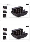
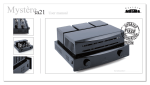
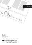
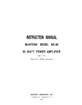
Artemis Labs DP-2
Push-Pull Stereo Power Amplifier
Operating Manual
Important Safety Instructions
1. Read these instructions.
2. Keep these instructions.
3. Heed all warnings.
4. Follow all instructions.
5. Do not use this apparatus near water.
6. Clean only with a dry cloth.
7. Do not block any ventilation openings. Install in accordance with the manufacturer’s instructions.
8. Do not install near any heat sources such as radiators, heat registers, stoves, or other apparatus.
9. Do not defeat the safety purpose of the grounding-type plug. A grounding-type plug has two
blades and a third grounding prong. The third prong is provided for your safety. If the provided
plug does not fit into your outlet, consult an electrician for replacement of the obsolete outlet.
10. Protect the power cord from being walked on or pinched, particularly at plugs, convenience
receptacles, and the point where they exit from the apparatus.
11. Only use attachments/accessories specified by the manufacturer.
12. Unplug this apparatus during lightning storms or when unused for long periods of time.
13. Refer all servicing to qualified service personnel. Servicing is required when the apparatus
has been damaged in any way, such as if the power-supply cord or plug is damaged, liquid has
been spilled inside the appliance or it has been exposed to moisture, the appliance does not
operate normally, or has been dropped.
14. WARNING: To reduce the risk of fire or electric shock, do not expose this apparatus to rain
or moisture.
Explanation of Safety Symbols:
CAUTION
ATTENTION
RISK OF ELECTRIC SHOCK
DO NOT OPEN
RISQUE DE CHOC ELECTRIQUE
NE PAS OUVRIR
CAUTION: To reduce the risk of electric shock, do not remove the covers.
No user-serviceable parts inside.
Refer Servicing to qualified service
personnel.
This symbol is intended to alert the user to the presence of
uninsulated “dangerous voltage” within the product’s enclosure
that may be of sufficient magnitude to constitute a risk of electric shock to persons.
This symbol is intended to alert the user to the presence of
important operating and maintenance (servicing) instruction in
the literature accompanying the appliance.
Page 2
INTRODUCTION & SPECIFICATIONS
The Artemis Labs DP-2 Power Amplifier is a purist design comprising a pair of mono-block amplifiers.
It uses the classic 2A3 directly-heated triodes in push-pull class-A with transformer phase splitting.
Careful power supply filtering and regulation of critical voltages ensure stable, quiet operation.
Given that the DP-2 amplifier puts out about 10 watts per channel, it must be used with relatively efficient loudspeakers. The minimum efficiency required depends on many factors including room size,
room absorption, preferred listening levels, etc., but in general, an efficiency of 92dB or higher per watt
at 1 meter is needed. Work with your dealer for the best speaker combination for your listening set-up.
The DP-2 is conservatively designed and is built to last for many years. The only maintenance needed
is the occasional replacement of tubes. Please read this entire user’s manual so that you can understand
all the features and get the most from the DP-2. The Warranty is on a separate card. Read it and send it
in to get full warranty coverage.
SPECIFICATIONS:
Input Impedance: 100K ohms
Rated Output Loads: 4 and 8 ohms
Sensitivity (8 ohm load, 1KHz): 0.9Vrms in for 8W out
Frequency Response & Distortion:
1 watt output:
Frequency Response: 20Hz – 40KHz +/- 1dB
THD+N at 1KHz: < 0.5%
8 watts output:
Frequency Response: 20Hz – 40KHz +/- 1dB
THD+N at 1KHz: < 2%
10 Watts output:
Frequency Response: 20Hz – 40KHz +/- 1dB
THD+N at 1KHz: < 4%
Damping Factor: 2.8 (not including voice coil resistance)
Output Noise: (grounded input, 8 ohm load, rms detector):
22Hz - 30KHz: < -85dB below 10W output
“A-weighted”: < -95dB below 10W output
Mains Voltage: Wired at factory for one of the following voltages: 100, 110, 120, 220, 230, 240V, 50 to 60Hz.
Power Consumption (rms) : 135 Watts nominal, 150 Watts maximum.
Size (each amplifier): 12 ¼" (311 mm) Height, 8 ½" (216 mm) Width, 17 ½" (445 mm) Depth
Weight (each amplifier): 40 lbs/18 Kg, 45 lbs/20.5 Kg (shipping weight)
Note: These specifications are subject to change at any time.
Page 3
REAR PANEL
Input
Speaker Connections
IEC Power Connector
Voltage Rating
Fuse Rating
Fuse
The rear panel of a single channel of the DP-2 amplifier is shown above. Note that the component placement for the two amplifiers are mirror images of each other.
The amplifier is driven by RCA cables connecting to the Input Connectors.
The speaker cables connect to the Speaker Connectors. Either banana jacks, wires, or spade
lugs can be used. If bare wire is used, be careful that no stray strands get loose that could
cause a short-circuit. The “Common” or “Ground” lead connects to the black jack, marked
“0”. The “Hot” lead goes to either the 4 ohm or 8 ohm red jacks, depending on the speaker
used.
Make sure that the Voltage Rating of your DP-2 matches the power mains voltage at your
location. The voltage is changed by internal rewiring, which can be done by Artemis Labs or
by a qualified technician. The Fuse is a 1" x 1¼" “3AG” Slow-blow type. Its value is given
on the Voltage Rating sticker.
A power cord is supplied with each unit. If the mains plug does not match your socket,
contact your dealer to exchange the cord for the correct type. The power cord plugs into the
IEC Power Connector. If the power cord is frayed or damaged, replace it with a new one.
Use only power cords that meet the safety standards of your location.
Page 4
INSTALLATION & OPERATION
To install the DP-2 Amplifiers, follow these steps:
1. Locate the DP-2 amplifiers where they can receive adequate fresh air for cooling. Do not block the
cooling holes on the bottom, i.e. do not set directly on carpet.
2. Connect the amplifier to the signal source by RCA interconnect cables to the left and right inputs.
The DP-2 has no volume control, so the signal source must have some means of controlling the signal level.
Do not change cables while the DP-2 is power-on.
3. Connect the speakers to the DP-2 by speaker cables to the output banana jacks. Choose the impedance so that it is equal to or lower than the rated impedance of the speaker. On highly-sensitive 8ohm speakers, it may be helpful to connect them to the 4-ohm outputs.
The amplifier must not be run with the outputs unconnected. If only one channel is used or while
being tested, dummy load resistors should be connected to the unused outputs. These can be 8 to 20
ohms, rated at least 10 watts.
4. Connect the DP-2 to an AC power source. It consumes 135 watts when running, so any power
conditioning, if used, must accommodate this power level. If problems with hum occur, it is recommended that the signal source and DP-2 be connected to the same AC outlet.
If the power fuse is blown by lightning or another kind of power surge, contact AYDN for authorization to return the DP-2, even if it still works.
The Power Switch on the front of the amplifier chassis applies power when flipped up. The Power
Indicator will glow green. After about a 45 second warm-up the DP-2s are ready for use.
TUBES
There are four tube types used in the DP-2 amplifier. Their use, history, and replacement strategy are
described here.
For best performance, the tubes should be periodically tested (between several months to several years,
depending on the amount of use) on a quality tube
tester (such as a Hickok, TV-7/U, or similar tester). If
a bad tube is suspected and a tube tester is not available, try substituting a known good spare tube to see
if the problem goes away.
12AU7/ECC82 - One-half of this twin triode is used as
the first audio amplifier. This is a very common type,
both for new production and New Old Stock (N.O.S.),
so there are many opportunities to try different brands.
The 12AU7 was designed by RCA and announced in
1946. It consists of two 6C4 triodes in a single envelope and is similar, although with lower power, to the
6SN7GT dual triode. It was very widely used in audio,
television, industrial and military applications. The
ECC82 is a European designation for the 12AU7.
There are many variations of the 12AU7 which can be
used in the DP-2. For example, the 5814 and 6189 are
ruggedized types that are compatible.
Since only one-half of the tube is used and the left and
right chassis are wired to different sections, the two
tubes can be swapped to use the fresh sections, essentially doubling the tube life. A worn-out tube will produce a dull or distorted sound.
KT88 - This triode-connected tube is used as the driver
tube. This is similar to the 6550, which can be used
here, also.
The KT88 was designed by M.O. Valve in England in
the mid-1950s. It is very similar to the 6550, designed in
America by Tung-Sol in 1954. Modern KT88s are made
in China, supposedly on the original M.O.V. tooling.
Page 5
TUBES
Occasionally a KT88 will be found that is too microphonic, i.e. is very sensitive to mechanical vibrations.
All tubes are microphonic to a degree, but if sound is
heard from the speakers if the chassis is lightly tapped,
then a different KT88 should be used.
The normal failure mode for these tubes is wear-out of
the cathode coating, resulting in low current and higher
distortion. However, if the tube goes gassy, it is possible
for the tube to arc over, which in the worst case will cause
the fuse to blow.
Since the KT88 is run very lightly in the DP-2, it should
last a long time, and fail by eventual cathode wear-out.
There is no need to match the two KT88s, since each
one is used for each channel and is individually biased.
5U4GB - This is the high-voltage power supply rectifier.
Although any rectifier with the same pin-connections
and power ratings as the 5U4GB or the Western Electric
type 274B could be used, other types may produce an
incorrect high voltage. Only exact equivalents of the
5U4GB (such as the 5U4G, 5AS4, Russian 5Ц3C, etc.) or
the 274B are recommended.
2A3 - This type is used as the power output tube, and
is crucial to the sound quality and power output of the
amplifier. The 2A3s on each chassis should be matched
pairs to insure the best low frequency response and
lowest distortion. Do not use other triodes, such as the
300B or PX-4, since their filament voltage is different
than the 2A3.
Depending on the tolerances of the tube sockets and
pins, it may be possible to incorrectly insert the 2A3s,
causing possible damage to the amplifier. Make sure the
two large pins are inserted facing the outside edge of the
chassis, as shown in the diagram below.
The 2A3 was designed by RCA and announced in 1932.
The very early RCA 2A3s had a single plate, but all later
American-built 2A3s have the “double-plate” construction, essentially two triodes in parallel. Modern 2A3s are
made with either single or double plates.
2A3
The 5U4GB was brought out by all the major American manufacturers in 1954, and was an updated version
of the 5U4G (1939) which was an octal version of the
5Z3, designed in 1934 by RCA. It was very widely used
in televisions, audio amps, and industrial equipment in
America.
These rectifier tubes are exposed to high voltages and
currents, and may fail by arcing. This will typically blow
the fuse. Otherwise, failure is indicated by cathode wearout, which will reduce the high voltage and hence cause
higher distortion.
Do not use plug-in solid-state rectifiers, since their fast
turn-on and lower voltage drop will unduly stress the
amplifier.
274B / 5U4G
274B / 5U4G
Artemis Labs
DP-2
Artemis Labs
DP-2
Push-Pull Amplifier
12AU7 / ECC82
2A3
2A3
Push-Pull Amplifier
12AU7 / ECC82
6550 / KT88
6550 / KT88
The tube locations are marked on the black plates on the
top of the chassis. Note that on both the left and right
amplifiers, the two large pins of the 2A3s face right when
viewing the front of the chassis, as shown above.
Page 6
2A3
SIMPLIFIED SCHEMATIC
�������
��������
�����
����
�����
���
100K
Low-Drop
2.5V Regulator
�����
��
�����
Artemis Labs
Line
voltages
available:
100V,
110V,
120V,
220V,
230V,
240V
50/60Hz
��������������
��
�������
��������������������
��������������������
�����������������
CIRCUIT DESCRIPTION
The Artemis Labs DP-2 is a modern version of the
classic push-pull directly-heated triode amplifier.
Amplifiers similar to the DP-2 were made right from
the start of the availability of the 2A3 in 1932. As
the use of pentodes spread in the 1930s, the directly
heated triode amplifier became uncommon, but it
was revived after World War II with the rise of standalone high-fidelity amplifiers. In the United States
the most notable examples were the Brook Amplifiers,
made from 1947 to the mid-1950s.
The cheapness and high power of push-pull beam
power tube amplifiers again pushed directly-heated
triode amplifiers to obscurity in the mid-1950s. The
revived interest in tube audio in the 1970s and ’80s
brought back the use of triodes, first in Japan, and
later elsewhere. The resulting demand for the obsolete
N.O.S. triodes pushed their prices sky-high, but there
are now several manufacturers of quality filamentary
triodes, with the 2A3 being one of the most commonly manufactured.
The Artemis Labs DP-2 is a straightforward design
with a two-stage driver transformer-coupled to a
push-pull output stage. The only modern features are
a 2.5VDC regulated filament supply for the 2A3s and
a MOSFET source follower voltage regulator for the
driver stage.
The driver circuit uses the medium-mu 12AU7 triode
capacitively-coupled to a triode-connected KT-88.
Page 7
CIRCUIT DESCRIPTION
The use of such a large driver tube here may seem
unconventional, but its low plate resistance and low
distortion work well in driving the interstage transformer to its full bandwidth. The frequency response
of the driver stage is further improved by the use of
several dB of feedback from the KT88 plate to the
12AU7 cathode. This is low enough to avoid the hard,
cold sound caused by large amounts of feedback. The
inductive nature of the interstage transformer has the
benefits of making the KT88 run into effectively and
infinite load, which gives the lowest distortion, and
allowing to plate voltage to swing up to twice the plate
supply voltage, which further reduces distortion and
increases the headroom.
The output stage uses two 2A3 triodes in push-pull.
Cathode bias is used, which is essentially self-correcting, eliminating the need for a bias control. The two
tubes should be matched, however, for lowest distortion. The low grid-circuit resistance provided by
the interstage transformer helps keep the 2A3’s bias
stable, even if the tubes are slightly gassy or have grid
current. It also helps reduce “blocking” if the grids are
momentarily over-driven.
Artemis Labs products
are distributed by:
Page 8
The 2A3’s filaments are driven by a solid-state low
voltage-drop regulator that supplies a clean, stable 2.5
volts. The problems of filament hum are eliminated
by the use of this DC power supply. A choke-input
filter is used for the filament supply to reduce current
spikes and improve the power factor of the power
supply.
The plate voltage for the two driver stages is regulated
by a MOSFET source-follower. This reduces any lowfrequency coupling from the output stage to the input
stages and also isolates the drivers from power supply
hum and line-voltage variations. The relatively low
gain of the source follower, compared to an op-amp
based regulator, gives decent regulation without the
“solid-state sound” typical of high-gain regulators.
The high voltage power supply uses a filamentary rectifier, the 5U4GB, with a conventional pi-filter circuit.
The power transformer has primary taps to allow use
with virtually any AC power source in the world. The
voltage taps are soldered internally and should only
be changed by a qualified technician or by AYDN.
AYDN Vacuum Tube Audio
679 Easy Street, Unit E
Simi Valley, California 93065 USA
www.aydn.com
Tel: +1 818 216-7882
email: [email protected]
rev 1.0