1
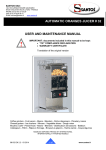
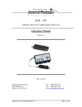
PSM-003
Micro Polarization
Controller/Scrambler
User Guide
Version: 1.1
Date: April 9, 2015
PSM-003 User Guide
General Photonics, Incorporated is located in Chino California.
For more information visit the company's website at:
www.generalphotonics.com
or call 909-590-5473
GP-UM-PSM-003-11
Page 2 of 19
PSM-003 User Guide
SAFETY CONSIDERATIONS
The following safety precautions must be observed during operation of this product.
Failure to comply with these precautions or with specific warnings elsewhere in this manual
violates safety standards of design, manufacture, and intended use of the product. General
Photonics assumes no liability for customers’ failure to comply with these requirements.
Before operation, the user should inspect the product and review the manual carefully.
Use only in a safe work environment in terms of temperature, humidity, electrical power and risk
of fire or shock. The product is designed for indoor use. Avoid exposure to liquids or water
condensation. Provide adequate ventilation for cooling.
Operate the product on a stable surface. Avoid excess vibration.
Standard laser safety procedures should be followed during operation.
After powering off the PSM-003, wait at least 5 seconds before powering it back on. If
this procedure is not followed, the PSM-003 may not function properly.
Never look into the light source fiber connector when the light source is
turned on. THE OUTPUT LIGHT FROM A HIGH POWER LASER IS HARMFUL
TO HUMAN EYES. Follow industry standard procedures when operating a
high power laser source.
GP-UM-PSM-003-11
Page 3 of 19
PSM-003 User Guide
GP-UM-PSM-003-11
Page 4 of 19
PSM-003 User Guide
Section 1.0
Overview ............................................................... 7
1.1 Principle of Operation......................................................... 7
1.2 Device Configurations and their Functions ......................... 9
Section 2.0
Features .............................................................. 11
2.1 Optical Features ............................................................... 11
2.2 Electrical Features ............................................................ 11
2.3 Dimensions and Mounting Holes....................................... 13
Section 3.0
Operation Instructions ........................................ 15
3.1 Unpacking ........................................................................ 15
3.2 Operation ......................................................................... 15
Polarization Controller ..................................................15
Polarization Scrambler (Continuous) ............................16
Polarization Scrambler (Random) .................................16
3.3 Driver Board (Optional) .................................................... 17
Setup.............................................................................18
Polarization Controller ..................................................18
Polarization Scrambler (Continuous) ............................18
Polarization Scrambler (Random) .................................18
Section 4.0
Specifications ..................................................... 19
Optical...........................................................................19
Electrical .......................................................................19
Physical and Environmental ..........................................19
GP-UM-PSM-003-11
Page 5 of 19
PSM-003 User Guide
GP-UM-PSM-003-11
Page 6 of 19
PSM-003 User Guide
Section 1.0
Overview
The PSM-003 is an OEM micro polarization controller that integrates miniature sized
electronic driving/control circuitry with General Photonics’ all-fiber dynamic polarization controller.
The state of polarization (SOP) of the output light is controlled via three 0-5V analog control
voltages. The device requires a ±12 VDC power supply, and the power consumption is low enough
for it to be powered by batteries or a wall-plug transformer.
Figure 1 PSM-003 micro polarization controller/scrambler
1.1 Principle of Operation
The PSM-003 is based on a PolaRite™ III polarization controller, which consists of 3 fiber
squeezers oriented 45° from each other. Each fiber squeezer is driven by an applied voltage
signal. Squeezing the optical fiber produces a linear birefringence in the fiber and thus alters the
state of polarization of a light signal passing through it.
An arbitrary polarization state of monochromatic light can be represented by a single point
on the Poincaré Sphere, as shown in Figure 2. Increasing the voltage on one fiber squeezer (X1 or
X3) increases the pressure from that squeezer, causing the polarization state to rotate clockwise
about the OQ axis. Decreasing the voltage causes the point to rotate counterclockwise. Similarly,
increasing or decreasing the voltage on a second fiber squeezer (X2) oriented 45° from the first
one causes the polarization state to rotate clockwise or counterclockwise about an axis (OH axis)
orthogonal to the first one.
GP-UM-PSM-003-11
Page 7 of 19
PSM-003 User Guide
LCP
R
V
X2
O
H
Q
X1, X3
RCP
SOP on Poincaré Sphere
H: Horizontal Linear Polarization
V: Vertical Linear Polarization
Q: +45 degree Linear Polarization
R: −45 degree Linear Polarization
Increase the
Applied Voltage
CW
V
Q
X1, X3
LCP: Left Circular Polarization
RCP: Right Circular Polarization
CW
H
CCW
Q
CCW
H
R
X2
Decrease the
Applied Voltage
Figure 2 Poincaré Sphere SOP representation and illustration of effects of fiber squeezers
The half-wave voltage Vπ (λ) at wavelength λ can be calculated from
Vπ(λ) = Vπ (1550 nm)
× λ /1550
where Vπ (1550 nm) is the half-wave voltage at 1550 nm. For example, the half-wave voltage at
1310 nm is 85% of the half-wave voltage at 1550 nm.
By appropriately tailoring the control signals, the polarization controller can be made to
perform various polarization control or scrambling functions.
GP-UM-PSM-003-11
Page 8 of 19
PSM-003 User Guide
1.2 Device Configurations and their Functions
The PSM-003 is available in 3 different configurations, selected at the time of order:
1.
Polarization Controller
2.
Fixed rate, continuous-trace polarization scrambler
3.
Fixed rate random scrambler
For the polarization scrambler configurations, the scrambling rate is also specified at the
time of order.
The functions of the three types of PSM-003 are described below:
Polarization controller: The SOP of the output
light can be set or modulated by applying a 0-5V analog
control voltage to each of the 3 fiber squeezers. The
control signal can be a DC voltage or a sine wave of
frequency up to 10 Hz.
Figure 3 SOP change by sequentially
changing control voltages of different
channels
Continuous
polarization
scrambler:
The
PSM-003
generates a continuous polarization trace that evenly covers the
Poincaré sphere at a preset rate.
Figure 4 Continuous scrambling trace
GP-UM-PSM-003-11
Page 9 of 19
PSM-003 User Guide
Random polarization scrambler: The PSM-003 generates
discrete random points evenly distributed on the Poincaré
sphere.
There are two modes of operation:
Internal trigger: Points are automatically generated at a preset
rate.
External trigger: PSM-003 generates one random point per
trigger pulse received.
Figure 5 Random scrambling trace
GP-UM-PSM-003-11
Page 10 of 19
PSM-003 User Guide
Section 2.0
Features
2.1 Optical Features
The PSM-003 has two fiber pigtails to accommodate the input and output optical signals.
2.2 Electrical Features
The electrical interface to the PSM-003 is a 10-pin IDC connector. The connector diagram
is shown below. The tables list the pin definitions for the connector for the different PSM
configurations.
2
1
4
3
6
5
8
7
10
9
Figure 6 PSM-003 electrical connector pinout
Table 1 Electrical connector pin definitions for PSM-003-C (controller)
Pin #
Label
I/O
1
AIN1
I
Analog input axis 1
DC 0 to 5V
2
AIN2
I
Analog input axis 2
DC 0 to 5V
3
AIN3
I
Analog input axis 3
DC 0 to 5V
4
N/C
Not connected
5
N/C
Not connected
6
N/C
Not connected
7
EN
I
Enable/Disable
TTL, Low=Enable, High=Disable
8
+12V
I
+12V Power input
DC+12V±5%, current >25mA
9
−12V
I
−12V Power input
DC−12V±5%, current >25mA
10
GND
-
Ground
System ground
GP-UM-PSM-003-11
Description
Range and Function
Page 11 of 19
PSM-003 User Guide
Table 2 Electrical connector pin definitions for PSM-003-S (Continuous scrambler)
Pin #
Label
I/O
Description
Range and Function
1
N/C
Not connected
2
N/C
Not connected
3
N/C
Not connected
4
N/C
Not connected
5
N/C
Not connected
6
N/C
Not connected
7
EN
I
Enable/Disable
TTL, Low=Enable, High=Disable
8
+12V
I
+12V Power input
DC+12V±5%, current >25mA
9
−12V
I
−12V Power input
DC−12V±5%, current >25mA
10
GND
-
Ground
System ground
Table 3 Electrical connector pin definitions for PSM-003-S (Random scrambler)
Pin #
Label
I/O
Description
Range and Function
1
N/C
Not connected
2
N/C
Not connected
3
N/C
Not connected
4
N/C
Not connected
5
EXT
I
Trigger Select
TTL, Low = external, High = internal
6
TR
I
External Trigger
TTL, triggers on rising edge
7
EN
I
Enable/Disable
TTL, Low=Enable, High=Disable
8
+12V
I
+12V Power input
DC+12V±5%, current >25mA
9
−12V
I
−12V Power input
DC−12V±5%, current >25mA
10
GND
-
Ground
System ground
Voltage/Current Guidelines:
Analog Control Voltages (PSM-003-C: AIN1-3):
Voltage Range: 0 to 5V
Drive current: <1.5 mA
Digital TTL (EN, EXT, TR):
Logic Level
Voltage
Current (TTL circuit capacity)
High
3 to 5V
>400µA
Low
0 to 0.4V
>1mA
GP-UM-PSM-003-11
Page 12 of 19
PSM-003 User Guide
2.3 Dimensions and Mounting Holes
The PSM-003 has 4 mounting holes on the bottom of the enclosure. Package dimensions
and the locations and sizes of mounting holes are given below.
Figure 7 Dimensions and mounting hole information
All dimensions given in inches.
GP-UM-PSM-003-11
Page 13 of 19
PSM-003 User Guide
GP-UM-PSM-003-11
Page 14 of 19
PSM-003 User Guide
Section 3.0
Operation Instructions
3.1 Unpacking
Inspect PSM-003 for any physical damage due to shipping and transportation. Contact
carrier if any damage is found. Check the packing list to see if any parts or accessories are
missing.
Packing List
Item #
Description
1
PSM-003
2
Electrical connection cable
3
User Guide
4
Control board (optional)
5
Power adapter (optional; only for devices with control board)
3.2 Operation
Polarization Controller
1.
Connect optical input and output to PSM-003.
2.
Make the necessary electrical connections to the 10-pin IDC connector (see Table 1 for pin
definitions). For a polarization controller, these include:
a.
Power supply: ±12VDC/25 mA
b.
Enable/Disable signal: TTL level. Low = Enabled, High = Disabled. The default
condition is enabled, so if this pin is left unconnected, the controller will be
enabled. For a controller, the Enable/Disable function acts as a position lock; while
disabled, the controller remains in its current setting. It does not respond to
further changes in control voltage until enabled.
c.
Analog control voltage for each of the 3 channels of the polarization controller: The
user can manually adjust the output SOP by changing the value of DC control
voltages to the different channels, or can generate periodic SOP traces or patterns
on the Poincaré sphere by using periodic waveform control voltages. Guidelines for
control voltages:
i. Voltage range: 0 to 5V
ii. Frequency limit for periodic waveform inputs: 10 Hz.
GP-UM-PSM-003-11
Page 15 of 19
PSM-003 User Guide
Polarization Scrambler (Continuous)
1.
Connect optical input and output to PSM-003.
2.
Make the necessary electrical connections to the 10-pin IDC connector (see Table 2 for
pin definitions). For a continuous polarization scrambler, these include:
a.
Power supply: ±12VDC/25 mA
b.
Enable/Disable signal: TTL level. Low = Enabled, High = Disabled. The default
condition is enabled, so if this pin is left unconnected, the scrambler will be
enabled. For a scrambler, the Enable/Disable function acts as a pause/resume
function; while paused, the SOP remains at the setting at which the
scrambling was paused. When resumed, the SOP variation begins from that
state.
Polarization Scrambler (Random)
1.
Connect optical input and output to PSM-003.
2.
Make the necessary electrical connections to the 10-pin IDC connector (see Table 3 for
pin definitions). For a random polarization scrambler, these include:
a.
Power supply: ±12VDC/25 mA
b.
Enable/Disable signal: TTL level. Low = Enabled, High = Disabled. The default
condition is enabled, so if this pin is left unconnected, the scrambler will be
enabled. For a scrambler, the Enable/Disable function acts as a pause/resume
function; while paused, the SOP remains at the setting at which the
scrambling was paused. When resumed, the SOP variation begins from that
state.
c.
Trigger select: This selects between external and internal triggering. In
internal trigger mode, the PSM-003 generates random SOPs at a preset rate
determined at the time of purchase. In external trigger mode, the PSM-003
generates one random point per trigger pulse received. TTL Low = external
trigger; TTL High = internal trigger. The default state is internal trigger.
d.
External trigger signal:
i.
Trigger edge: Rising edge
ii.
Voltage levels: TTL levels
iii. Minimum pulse width: 1 ms
iv. Maximum pulse frequency: 10 Hz
GP-UM-PSM-003-11
Page 16 of 19
PSM-003 User Guide
3.3 Driver Board (Optional)
General Photonics offers an optional manual control driver board for the PSM-003. The
purpose of the board is to facilitate testing and integration of the PSM-003. The user controls the
PSM-003 via sliders, switches, and buttons on the control board. The board comes with a power
adapter that plugs into a wall power supply.
Driver board dimensions: 3.5 × 3.5 × 0.7 inches.
A) 3 axis analog voltage
indicator LEDs, for
controller only
B) Enable/Disable switch and LED
indicator
Up:
disabled
Down: enabled, LED on
C) Power supply
indicator LEDs
D) 10-Pin connector
connects PSM-003 to
control board
E) Reserved switch
and LEDs,
Not used in current
version
I) Auto/Manual trigger
mode selection switch
for random scrambler
F) Power supply jack
Use only with AC adapter
provided with board
H) 3 slide potentiometers
3 axis voltage adjustment
For controller only
G) Trigger push button, for
random scrambler only
Figure 8 PSM-003 controller board
GP-UM-PSM-003-11
Page 17 of 19
PSM-003 User Guide
Setup
1.
Connect optical input and output to PSM-003.
2.
Make sure the PSM-003’s 10-pin electrical connector is connected to the corresponding
connector on the driver board (middle right in Figure 8). The board and cable
connectors are keyed and can only be connected in one orientation.
3.
Connect the external power adapter to the board’s power jack and plug it into the wall
electricity supply. Both power indicator LEDs on the board should turn on.
Power supply adapter output:
4.
12VAC/500 mA
Move the Enable/Disable switch to the Enabled position.
Polarization Controller
Use the three sliders to control the voltage input to the three channels of the polarization
controller.
The Enable/Disable switch can be used to lock in the current setting. If the switch is in the
Disable position, the polarization controller will not respond to slider movement.
Polarization Scrambler (Continuous)
The PSM-003 performs continuous scrambling at a preset rate as long as it is enabled. Use
the Enable/Disable switch to pause and resume scrambling.
Polarization Scrambler (Random)
The trigger selection switch selects between automatic and manual triggering of random
SOP generation.
Switch position: UP
DOWN
Automatic triggering
Manual triggering
In automatic mode, the PSM-003 generates random SOPs at a preset rate. In manual
mode, the PSM-003 generates one random SOP each time the push button (immediately to the
left of the power jack in the diagram) is pressed.
Use the Enable/Disable switch to pause and resume scrambling.
GP-UM-PSM-003-11
Page 18 of 19
PSM-003 User Guide
Section 4.0
Specifications
Optical
Operating Wavelength
1260-1650 nm standard
# of control axes
3
Insertion Loss
Measurement grade:
0.05 dB, excluding connectors
Control grade:
0.1 dB, excluding connectors
> 65 dB, excluding connectors
Return Loss
PMD
Measurement grade:
Control grade:
Measurement grade:
Control grade:
< 0.05 ps
Optical Power Handling
300 mW
Preset scrambling rates
(select when ordering)
Continuous scrambling
0.0192π, 0.096π, 0.48π, 2.4π, 12π, 60π rad/s
Random scrambling
0.1, 0.2, 1, 5 points/s
Activation Loss
PDL
0.01 dB
0.1 dB
<0.01 dB
<0.1 dB
Electrical
Control voltage range
0 to 5V
Rise and Fall Time
<5 ms/V (or 12.5 ms/Vπ)
Vπ
2.5V (typical), 3V (maximum) at 1550nm
Input sine wave frequency
10 Hz max.
Electrical interface
8-wire flat cable
Electrical connector
IDC 10-pin (2×5), 0.1 inch grid
Power Supply
±12VDC/25 mA
*
Power consumption
<0.6W typical
* Controller: 5V input on all 3 axes at 25°C
Scrambler: Continuous scrambling at 12π rad/s and 25°C.
Physical and Environmental
Fiber Type
9/125 µm single mode fiber standard
Operating temperature
−10 °C to 70 °C
Storage temperature
−40 °C to 85 °C
Dimensions
2.58”(L) × 1.25”(W) × 0.63”(H)
(6.54 (L) × 3.18 (W) × 1.60 (H) cm)
2 Oz. (50g)
Weight
GP-UM-PSM-003-11
Page 19 of 19