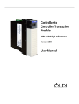
1
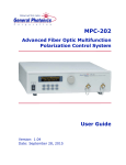
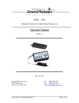
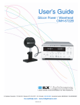
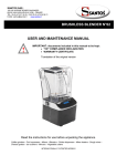
PCD – 104
Wide Bandwidth Fiber-Optic Polarization Scrambler
Operation Manual
April 22, 2011
General Photonics Corp.
5228 Edison Ave.
Chino, CA 91710 USA
Document #: GP-UM-PCD-104-32
Ph: (909) 590-5473
Fax: (909) 902-5536
www.generalphotonics.com
Page 1 of 30
WARRANTY
All of General Photonics’ products have been inspected and found to comply with our
stringent quality assurance standards before shipping. If any damage occurs during
shipment, please contact the carrier and inform us or our distributors as soon as possible.
Please do not, under any circumstances, attempt user repair of any General Photonics
product. To avoid further damage, any repair of defective products must be performed by
well-trained engineers.
General Photonics warrants that this product will be free from defects in materials or
workmanship for a period of one year from the date of original shipment (listed on the
certificate of quality or packing list enclosed with the original shipment). A product
found to be defective during the warranty period will be repaired or replaced, at no
charge, at General Photonics’ option.
If a problem is found, please contact General Photonics for assistance. If necessary,
return the defective product, freight prepaid, clearly labeled with the RMA number, with
as complete a description of the problem as possible. The repaired or replacement product
will be returned, freight prepaid, as soon as possible.
The above warranty specifically excludes products that have been repaired or modified
by non-manufacturer-authorized personnel, as well as damage caused by misuse, abuse,
improper storage or handling, or acts of nature.
This warranty is in lieu of all other warranties, expressed or implied. General Photonics
will not be liable for any indirect or consequential damages or losses resulting from the
use of its products.
Document #: GP-UM-PCD-104-32
Page 2 of 30
SAFETY CONSIDERATIONS
The following safety precautions must be observed during operation, service and repair
of this instrument. Failure to comply with these precautions or with specific warnings
elsewhere in this manual violates safety standards of design, manufacture, and intended
use of the instrument. General Photonics Corp. assumes no liability for customers’ failure
to comply with these requirements.
• Before operation, the user should inspect the instrument and
review the manual carefully.
•
The instrument’s rear panel includes a chassis ground terminal for electrical
safety.
•
Make sure that the instrument is in a secured work environment (in terms of
temperature, humidity, electrical power, hazard due to fire or shock, etc.) for
proper operation.
•
Standard laser safety procedures should be followed during operation.
Document #: GP-UM-PCD-104-32
Page 3 of 30
Table of Contents:
WARRANTY ..................................................................................................................... 2
Section 1. Specifications:.................................................................................................... 5
Section 2. Overview:........................................................................................................... 6
Section 3. Feature Descriptions: ......................................................................................... 8
3.1 Optical Features: ....................................................................................................... 8
3.2 Electrical Features:.................................................................................................... 8
Section 4. Operation Instructions:..................................................................................... 12
4.1 Unpacking ............................................................................................................... 12
4.2 Front Panel Operation ............................................................................................. 12
4.3 Testing and Characterization: ................................................................................. 13
4.4 Remote control and programming: ......................................................................... 14
4.4.1
RS-232 operation ...................................................................................... 14
4.4.1.1 RS-232 connection.................................................................................... 14
4.4.1.2 Remote control programming ................................................................... 14
4.4.1.3 RS-232 troubleshooting ............................................................................ 16
4.4.2 LabView Control Program............................................................................... 16
4.4.3 Ethernet Control............................................................................................... 18
4.4.4 GPIB Control: .................................................................................................. 28
Section 5. Technical Support ............................................................................................ 29
Appendix A: PCD-104 Scrambling Frequency Distribution ............................................ 30
Document #: GP-UM-PCD-104-32
Page 4 of 30
Section 1. Specifications:
Physical Features:
Dimensions
Fiber Input/Output Connectors
Weight
Optical Characteristics:
Input/output fiber type1
Insertion Loss
2U 19” half-rack mount size
14” (L) × 8.5” (W) × 3.5” (H)
FC/PC, FC/APC, SC/PC or SC/APC
8 lb.
Operating wavelength range 2
Output degree of polarization3,4
Average PMD5
Intrinsic PDL5
Optical return loss5
Optical power handling
Residual amplitude modulation
Residual phase modulation
9/125 μm SM or compatible (standard)
< 0.05 dB (without connectors)
< 0.6 dB (with connectors)
Remote or manual selection of 980nm, 1060nm,
1310nm, 1480nm, 1550nm, 1600nm
>100 nm for a selected wavelength setting
< 5%
< 0.05 ps
< 0.05 dB
> 65 dB
> 1000 mW
< ± 0.01 dB
< 0.1 π
Electrical Characteristics:
Power Supply6
Power consumption
100~240 VAC, 50-60 Hz
12 Watts Typical
Center operating wavelength1
Scrambling frequencies4
Computer interface
Factory set fixed frequencies
Distributed between DC and >700 KHz
RS-232, GPIB, Ethernet
Environmental Requirements:
Operating Temperature
Storage Temperature
10 °C to 45 °C
−10 °C to 50 °C
Notes:
1. Please note that the fiber used determines the operating wavelength range. The standard
fiber covers wavelengths in the 1260-1650nm range. The PCD-104 can also be
configured to cover the 970-1300nm range using a different fiber. This fiber can handle
wavelengths up to 1650nm, but if it is coupled to SMF- 28 fiber, the performance may
not be quite as good as normal due to mode mismatch. Please contact General Photonics
for details.
2. Center wavelength ± 50 nm.
3. At 500 Hz detection bandwidth.
4. Measured by a photodetector at the PCD-104 output using an electrical spectrum
analyzer. A polarizer is placed in front of the photodetector to convert polarization
modulation to amplitude modulation.
5. Measured without connectors.
6. Power supply is universal, but different fuses are used for 110 and 220V line voltages.
Document #: GP-UM-PCD-104-32
Page 5 of 30
Section 2. Overview:
The PCD-104 is a polarization scrambler that integrates General Photonics’ awardwinning PolaRite™ II polarization controller/scrambler, a driver circuit, and a
microprocessor based electronic control circuit in a single enclosure, as shown in Figure
1. The PCD-104 employs continuous fiber construction that results in extremely low
optical insertion loss, polarization dependent loss, and polarization mode dispersion. It is
an ideal tool for optical measurement, device characterization, network conditioning, and
other polarization related applications.
Figure 1 PCD-104 polarization scrambler.
The polarization of light beams is an important factor in high-speed optical
communication network system design. As the bit rate increases, fiber optic
communication systems become increasingly sensitive to polarization related
impairments, including polarization mode dispersion (PMD) in optical fibers,
polarization dependent loss (PDL) in passive optical components, polarization dependent
modulation (PDM) in electro-optic modulators, polarization dependent gain (PDG) in
optical amplifiers, polarization dependent center wavelength (PDW) in WDM filters,
polarization dependent response (PDR) in receivers, and polarization dependent
sensitivity (PDS) in sensors and coherent communication systems.
Polarization scrambling can be used to mitigate the effects of many polarization related
impairments. Light is considered “scrambled” when the state of polarization (SOP) of
totally polarized light is made to vary randomly. At any instant of time, the SOP of the
light is well defined, and its degree of polarization (DOP) is close to 1. However, its
time-averaged DOP is close to zero. Therefore, the measured DOP of scrambled light
depends on the averaging time or the detection bandwidth of the observer.
The operation of the PCD-104 can be described as being based on the concept of a multistage birefringent modulator. Squeezing fiber can induce large birefringence in the fiber
via the photo-elastic effect, and can cause large polarization modulation if the input
polarization axis is offset by 45 degrees from the squeezing axis. A polarization
Document #: GP-UM-PCD-104-32
Page 6 of 30
insensitive scrambler can be constructed by cascading multiple fiber squeezers oriented
45 degrees from each other, as shown in Fig. 2.
Figure 2 Construction of a fiber-squeezer based polarization controller/scrambler.
In the PCD-104, each stage of the birefringent modulator operates at a different resonant
modulation frequency chosen to randomize the output polarization state with the highest
possible effective scrambling frequency. The drive voltage for each stage is also preset to
achieve minimum degree of polarization (DOP).
Microprocessor control provides the PCD-104 with greatly expanded capability, allowing
it to operate over a large temperature range and a wide wavelength band. It can also be
remote controlled via RS-232, GPIB or Ethernet interfaces. The standard PCD-104
covers the entire 1260-1650 nm fiber transmission window, while an ultra-wide
bandwidth version of the PCD-104 can cover an extended wavelength range from 970 nm
to 1650 nm.
Document #: GP-UM-PCD-104-32
Page 7 of 30
Section 3. Feature Descriptions:
3.1 Optical Features:
The PCD-104 has two fiber connectors, one for the input and the other for the output. The
input and output connectors are interchangeable unless the user specifies a special
connector configuration for the input/output fibers. Each fiber connector is equipped with
a universal connector interface (UCI), which features a male-type adapter top piece that
can be removed for direct access to the ferrule end for routine cleaning and maintenance
without removing the entire adapter from the panel. This feature helps avoid high
insertion loss, high return loss and measurement instability caused by dirty or
contaminated connectors. In addition, the universal interchangeable adapter allows the
end user to switch to ST, SC, or FC connectors without opening the instrument panel.
Although the PCD-104 is shipped with customer specified fiber adapters, other
interchangeable inserts are available. For additional information on different input fiber
adapter inserts, please contact General Photonics.
External fiber connectors should be cleaned using industry standard cleaning methods
before connection to the PCD-104. If this procedure is followed before each connection,
the instrument’s internal connector ferrules should not need regular cleaning. However,
high insertion loss or measurement instability that does not improve after cleaning the
external connectors may indicate that the instrument’s internal connector ferrule requires
cleaning.
The connector ferrule is contained in a universal connector interface consisting of a front
piece that connects to the external fiber connector, and a base piece that is mounted on
the front panel of the instrument. To clean the connector ferrule, first, make sure no
external connector is connected to the universal connector interface. Then, using a
Phillips screwdriver, remove the two small screws connecting the front and back parts of
the adapter, and carefully pull the front flange straight out. (Note: never remove the
adapter base from the front panel). The ferrule end should now be exposed. Clean the
ferrule using standard cleaning procedures (compressed air or a fresh lint-free tissue and
alcohol), taking care to avoid scratching the ferrule surface. Finally, replace the front
flange (position it so that the key notch faces up, and the small alignment pin lines up
with the hole in the base piece, before pushing it in) and the screws. For frequent
measurements, we recommend that the user prepare a patch cord fiber to avoid wear on
the internal connector.
3.2 Electrical Features:
The PCD-104 accepts standard 100-240VAC, 50-60 Hz wall power supplies. However,
110V and 220V line voltages require the use of different fuses. The fuses shipped with
the PCD-104 are chosen according to customer specification when the order is placed.
Due to high voltage, the following safety precautions must be exercised during operation.
Document #: GP-UM-PCD-104-32
Page 8 of 30
•
•
•
The ground pin on the power supply cord must be connected to earth ground of
the wall receptacle.
Never touch the boards inside the package without proper insulation.
The PCD-104 is not user serviceable. It can be serviced only by factoryauthorized personnel.
The front panel of the PCD-104 is shown in Figure 3. The power switch (Power),
wavelength indicator LED panel, wavelength select button, enable/disable button, and
input and output optical connectors are mounted on the front panel. The AC power plug,
fuse, and computer interface connectors (RS-232, GPIB, and Ethernet) are mounted on
the rear panel, as shown in Figure 4.
The PCD-104 includes RS-232, Ethernet, and GPIB interfaces for external computer
operation of the system. An RS-232 cable is provided for connection to a personal
computer. LabView™ (National Instruments, www.ni.com) control programs are
provided for control via different interfaces. Please see section 4.4 for control commands
and instructions for running control programs.
Figure 3 PCD-104 front panel layout
Front panel description:
Power: power on/off switch
Input: universal connector interface adapter for optical fiber input
Output: universal connector interface adapter for optical fiber output
Wavelength indicator LEDs: show currently selected wavelength
λ: Wavelength selection button- toggles through wavelength selections
Enable button: Enables/disables scrambler operation
Enable indicator LED: shows enable (lit)/disable (dark) status
Document #: GP-UM-PCD-104-32
Page 9 of 30
Figure 4 Rear panel layout.
Rear panel description:
USB: USB interface port – not used in PCD-104
RS-232: serial communication port
Ethernet: Ethernet interface port
GPIB: GPIB interface port
Line: external AC supply input connector, 110 V or 220 V
BNC: not used in PCD-104
: electrical ground connection
Document #: GP-UM-PCD-104-32
Page 10 of 30
Fuse location:
Figure 5 shows the location of the fuse compartment, directly under the power cord plug.
There are two fuses in the compartment- the one in use and a spare. The fuse further
inside the compartment is the active one, and the one closer to the compartment opening
is the spare.
If the fuse burns, open the compartment and move the spare to the holder further inside
the compartment. Make sure that the electrical supply meets the requirements of the
instrument before plugging it in again. Always replace the fuse with one with the exact
rating of the original.
Figure 5 Fuse compartment
Document #: GP-UM-PCD-104-32
Page 11 of 30
Section 4. Operation Instructions:
The PCD-104’s preset scrambling frequencies are selected for maximum Poincaré sphere
coverage, and are not user adjustable. The four drive frequencies produce a large number
of mixing frequencies distributed over a large spectrum range. The distribution of the
drive frequencies and their mixing products are shown in Appendix A.
Optical connections are required during setup of the PCD-104. Please follow all
applicable safety precautions when making these connections.
Warning:
•
Never look into the fiber connectors when the light source is turned on. THE
OUTPUT LIGHT FROM A HIGH POWER LASER IS HARMFUL TO
HUMAN EYES. Please follow industry standard procedures when operating
a high power laser source.
4.1 Unpacking
Inspect PCD-104 for any physical damage due to shipping and transportation. Contact
carrier if any damage is found. Check the packing list to see if any parts or accessories
are missing.
4.2 Front Panel Operation
Follow the steps below to operate the PCD-104 in a laboratory environment.
1. Connect power cord and plug it into wall receptacle. Make sure the ground pin of
the power cord is connected to earth ground. The PCD-104 power supply accepts
100-240VAC 50/60 Hz line voltages. Make sure that the fuse rating is consistent
with the line voltage used.
2. Turn on the power switch. Each wavelength indicator LED on the front panel will
light up sequentially as part of an initial power-up test. When the initialization
process is complete, the power indicator LED and the 1550 nm wavelength
indicator LED will stay on. The default wavelength setting is 1550 nm.
3. Use the Wavelength Select Button to select the desired operation wavelength.
The Wavelength Select Button cycles the wavelength setting sequentially through
the 980, 1060, 1310, 1480, 1550, and 1600 nm wavelength settings.
4. Press the Enable Button on the front panel to begin polarization scrambling. It is
recommended that the instrument be allowed to warm up for 20 minutes before
operation. The PCD-104 can be used in the meantime, but the DOP may not be
optimized before it is fully warmed up.
Document #: GP-UM-PCD-104-32
Page 12 of 30
5. Connect the input and output optical fibers. When the PCD-104 is enabled, the
output polarization state is scrambled for low DOP applications and
measurements. Fiber connections can be made before turning on the PCD-104 if
the optical system following the PCD-104 allows unscrambled polarized light at
its input.
6. To disable scrambling, press the Enable Button again. The LED next to the
Enable Button (Enable LED) will turn off, indicating that the PCD-104 is in
standby and is not actively scrambling.
7. To change to a different wavelength setting, first make sure that scrambling is
disabled (Enable LED is off), then use the Wavelength Select Button to select the
desired wavelength. Press the Enable Button to resume scrambling.
4.3 Testing and Characterization:
The PCD-104 can be serviced only by manufacturer-authorized personnel. There are no
user serviceable components in this instrument.
The performance of the PCD-104 can be tested with commercial polarization analysis
instruments or other established methods. Note that the DOP specification for the PCD104 is measured at a detector bandwidth of < 500 Hz. For high bandwidth detection
systems, the DOP can be obtained by averaging data samples within the desired time
frame using appropriate sampling systems or instruments.
DOP at the polarization scrambler output can be calculated from a simple intensity
measurement. In this measurement, a polarizer is placed between the scrambler output
fiber and a photodetector with a known detection bandwidth. The maximum and
minimum intensities Imax and Imin are then measured from the detector output. The DOP
in the measurement bandwidth can be calculated from
I
−I
DOP = max min × 100%
I max + I min
Note that Imax and Imin are measured within the desired bandwidth. Different detector
bandwidth settings will have different Imax and Imin values.
Document #: GP-UM-PCD-104-32
Page 13 of 30
4.4 Remote control and programming:
4.4.1
RS-232 operation
4.4.1.1 RS-232 connection
The RS-232 serial interface port allows the user to remote control the PCD-104. Any
program that supports RS-232 communication protocols can be used to send ASCII
commands to the PCD-104 to remotely access the system. The LabView program
provided with the instrument shows a programming example.
The RS-232 connector on the rear panel of the PCD-104 is a DB9 male connector. Use a
straight connection RS-232 cable to connect the PCD-104 to the RS-232 port of a
computer. To ensure proper communication, use a serial cable with direct pin-to-pin
connected wires (see Figure 6) at both ends of the cable.
GND
RXD
TXD
5 4 3 2 1
9 8 7 6
Figure 6 RS-232 connector pin assignment on PCD-104 rear panel.
4.4.1.2 Remote control programming
General Photonics provides a LabView program for remote control of the PCD-104. The
control software is included with the package. The user interface and program
instructions are described in section 4.4.2.
The following steps and commands are recommended to users who wish to write their
own control programs for remote operation of the PCD-104 using the RS-232
communication port.
1. Connect PCD-104 and PC using RS-232 straight cable (DB-9 female to female).
2. Referring to Table 1, send a command string to the PCD-104. There are many
programming languages that support serial communications, including Visual
Basic, LabView and C.
Document #: GP-UM-PCD-104-32
Page 14 of 30
Table 1 Remote Control Commands
Command
*ENA#
General Commands
Description
Response
Queries the PCD-104 identification.
*IDN GP-PCD-104#
Queries the PCD-104 Firmware Version
*VER V3-070504#
Queries the GPIB ADDRESS
*ADR 10# if address is 10
Set the GPIB Address
Example: *ADR 10#
Range: 0 to 30
Set Ethernet Mode and Query IP Address
Note: This set of commands must be sent from RS-232 only
Set PCD-104 to dynamic IP mode
OK
Set PCD-104 to static IP mode
OK
Request IP address
(IP Address will be returned)
(Note: Returns either dynamic or static IP
address, depending on which mode is active.)
Control Commands
Description
Response
Enable scrambling.
*E00#
*DIS#
*WAV N#
Disable scrambling
N can be one of 6 values;
Command
*IDN?
*VER?
*ADR?
*ADR NN#
~7DHCP#
~6STIP#
~8IP?#
*E00#
*E00#
*WAV 980# (Set wavelength to 980 nm)
*WAV 1060# (Set wavelength to 1060 nm)
*WAV 1310# (Set wavelength to 1310 nm)
*WAV 1480# (Set wavelength to 1480 nm)
*WAV 1550# (Set wavelength to 1550 nm)
*WAV 1600# (Set wavelength to 1600 nm)
Query Wavelength
Command
*WAV?
Description
Query the working wavelength
E00
E01
E02
E03
E04
E05
E06
E07
Response
*WAV 980#
*WAV 1060#
*WAV 1310#
*WAV 1480#
*WAV 1550#
*WAV 1600#
Response codes
Valid command received (No error)
Undefined Command
Missing start character
Missing or incorrect end character
Missing parameter
Invalid syntax found in command string
Parameter outside the allowed range
String of characters too long(>buffer limit)
Document #: GP-UM-PCD-104-32
Page 15 of 30
Notes:
a. The commands listed in table 1 are the same for all communication protocols:
RS-232, Ethernet, and GPIB, unless otherwise indicated.
b. Commands are case sensitive. Please use upper-case letters.
c. Sometimes communications may freeze (overflow) due to port conflict (this
mainly happens during ETHERNET control). In this case, the user may need to
restart the instrument to re-enable remote control.
d. Demo LabView programs (both source code and executable programs) have
been provided with the PCD-104. These programs can be used as for instrument
control (see section 4.4.2).
RS-232 Command notes:
1. RS-232 port uses asynchronous framing, 8 data bits, no parity bit, and 1 stop bit.
2. RS-232 baud rate: 9600 bps.
3. Only one command is allowed in each command string.
4.4.1.3 RS-232 troubleshooting
If a problem occurs during RS-232 control, please check the following:
1. Cable should be straight-wired: Select a straight-wired (pin-to-to pin wired)
cable;
2. Verify active Comm Port (COM1, COM2, etc.). This can be done by looking
under “Device Manager” on the “System Properties” screen: select Control
Panel → System Properties → Hardware → Device Manager, then Select
View → Devices by type, and look under Ports;
3. Verify Comm Port settings: 8 data bits, 1 stop bit, no parity bits;
4. Check baud rate: must be 9600 bps;
5. Check commands.
4.4.2 LabView Control Program
LabView control programs are provided for computer control of the PCD-104 via
different computer interfaces. Before running these programs, the user should determine
whether the LabView developing environment is installed in the control computer. If the
LabView environment (version 8.2 or above) is present, either the source code (vi) or the
executable versions of the remote control programs can be used without installing further
drivers.
Note: For simple control of the instrument, it is often easier to use the executable versions
of the program than the source code. However, the executable versions will not run
properly while LabView is running. If using the executable versions of the program on a
computer with LabView installed, the user should quit LabView before running them.
Document #: GP-UM-PCD-104-32
Page 16 of 30
If LabVIEW is not installed on the control computer, the user should set up the
LabVIEW Run-Time engine by running the programs under “\LVRunTimeEng_8.2” (on
the CD-ROM), and install the driver program for VISA (used for RS-232, distributed by
National Instruments) by running the program named “Visa400runtime.exe”. For further
details on Ethernet and GPIB control, see sections 4.4.3 and 4.4.4, respectively. Once the
necessary drivers and other setup parameters are in place, the executable programs in the
application directory can be run.
After the necessary drivers are installed, the programs (executable and/or source code)
should be copied to the hard drive and run from there.
Several versions of LabView control programs are provided. To locate a particular
program,
A. Under “LabView_SourceCode” directory (names ending in “.vi”)
• PCD_REMOTE.vi – Source code for the RS-232/GPIB control program for the PCD104;
• PCD_ETHERNET.vi – Source code for the ETHERNET control program for the
PCD-104 (see section 4.4.3)
• GP_SET_ETHERNET.vi –Source code for the ETHERNET setup program (see
section 4.4.3)
• PCD_GPIB_ADDRESS.vi – Source code for the program for querying/changing the
GPIB address (see section 4.4.4)
B. Under “LabView_Application” directory
• Executable programs with the same names (but with the “.exe” extension) and
functions as those under the “LabView_SourceCode” folder.
Note: Always close the control program (and LabView as well if using the VI version of
the control program) before turning off the instrument.
Figure 7 shows the screen layout of the PCD_REMOTE control program. The program
auto-senses which interface is being used and displays the appropriate port configuration
option. The control program interface is otherwise identical for RS-232 and GPIB
control. The Ethernet version of the control program has a similar interface, as discussed
in the next section. The description of each item on the screen is as follows:
Document #: GP-UM-PCD-104-32
Page 17 of 30
Figure 7 Remote control program interface
Port Configuration: Displays the selected port for the RS-232 or GPIB connection. If
the selected port and the actual connection do not match, the program will not
function correctly. Set the correct port number here. The port number can be
determined from the Device Manager (Note 2 in section 4.4.1.3) or from the
Measurement & Automation program from National Instruments. Note that the
port number cannot be set while the program is executing. Stop the program
first and choose the correct port if necessary.
Notes: (a) ASRL1:INSTR is the same as COM1 for RS-232.
(b) GPIB:XX:INSTR means the GPIB port with address XX.
Wavelength select: Pull-down menu for setting operation wavelength. Options are
980, 1060, 1310, 1480, 1550, and 1600. Scrambling must be disabled before
setting wavelength.
START: Enables (indicator green) or disables (indicator dark) scrambling.
4.4.3 Ethernet Control
1. Connections:
There are two connection configurations for Ethernet control:
a) Static IP: the administrator assigns the instrument a fixed IP address. In this
mode the instrument can be directly connected to the control PC, as shown in
Figure 8. For this configuration, a cross-linked network cable must be used.
Document #: GP-UM-PCD-104-32
Page 18 of 30
b) Dynamic IP: the DHCP server assigns the instrument an available address
when requested. Connect the instrument with a DHCP server (router or
exchange server), as shown in Figure 9. For this configuration, a standard
straight-linked network cable must be used.
PCD-104
PCD-104
Figure 8 Direct connection: PDLE-101 to PC
Figure 9 Connect PDLE-101 with DHCP server
2. Set Ethernet configuration and get IP address:
Open the LabVIEW program (GP_SET_ETHERNET.vi or GP_SET_ETHERNET.exe)
to set the Ethernet configuration.
NOTE: This program was designed for an RS-232 interface, so the instrument
should be connected to the computer via RS-232 before running it. Please see the
instructions at the beginning of section 4.4.2 for preparations to run an RS-232
LabView program. The program interface is shown below.
Select the correct serial (RS-232) port from the port configuration box at the top of
the screen. The baud rate should be set to 9600. Once these two parameters are set,
click the white arrow to run the program.
Document #: GP-UM-PCD-104-32
Page 19 of 30
The program has 3 tabs. The first, “GET IP CONFIG” is used to query the current IP
configuration of the PCD-104. When the “Get IP Config” button at the left of the
screen is clicked, the program will read back the instrument’s current IP address, net
mask, gateway, nameserver, and port, as well as whether the instrument is currently
set for static or dynamic IP addressing.
IP Config query screen- Static IP mode result
IP Config query screen- Dynamic IP mode result
Use this function to obtain the IP address, which is needed to use the Ethernet control
program for the PCD-104.
Document #: GP-UM-PCD-104-32
Page 20 of 30
The second tab, “MODE SETTING” allows the user to switch the PCD-104 between
static and dynamic IP addressing modes.
Ethernet mode selection screen- dynamic
Ethernet mode selection screen- static
Clicking the “OK” button for dynamic mode puts the PCD-104 into dynamic IP
mode. The instrument will obtain the dynamic IP information from the server. When
it is finished, the indicator for dynamic mode will turn green, and the Ethernet Mode
status box will say “DYNAMIC”.
Clicking the “OK” button for static mode puts the PCD-104 into static IP mode. The
instrument will recall the static IP settings from its memory. These can then be used
for communication. When it is finished, the indicator for static mode will turn green,
and the Ethernet Mode status box will say “STATIC”.
Document #: GP-UM-PCD-104-32
Page 21 of 30
The PCD-104 writes its most recently saved static IP settings and its active mode to
memory. If it is powered off while in static mode, when it is powered back on, it will
be in static mode, and the most recently saved set of IP configuration information can
be used for communication.
If the PCD-104 is powered off while in dynamic IP mode, when it is powered back
on, it will be in dynamic IP mode.
The third tab in the program, “STATIC IP SETTING”, allows the user to set the static
IP configuration information. Input the information into the corresponding boxes and
click the “SET” button. As each value is written, its indicator turns green. When all of
the information is successfully stored, the “Set OK” indicator will turn green.
Static IP setup screen.
Notes on configuration:
The net mask and gateway should be the same as those for the control computer (see
example below). The first 3 groups of numbers in the IP address should be the same as
those for the control computer (192.168.2, for example). The last number can be any
available number, but cannot be the same as the IP address of the control computer. If the
last number of the computer’s subnet mask is n, the available IP address range is n+1 to
254. In this example, n = 0, so the available IP addresses are 1 to 254. If the computer’s
IP address is 17, for example, the user can set the IP address for the PCD-104 to any
number in the range 1-254 except 17.
To find the IP information for the control computer for static IP mode:
Check the computer’s IP address:
Control Panel → Network and Dial-up Connections → Local Area Connection:
Document #: GP-UM-PCD-104-32
Page 22 of 30
→ Properties (on “General” tab)
→ Internet Protocol → Properties:
Document #: GP-UM-PCD-104-32
Page 23 of 30
Write down the IP address, subnet mask, and gateway.
Document #: GP-UM-PCD-104-32
Page 24 of 30
Dynamic IP configuration using a DHCP server:
To use dynamic IP address assignment, make sure that the DHCP server, switch,
computer and PCD-104 are correctly connected as shown in Figure 9. Check that the
correct cables are used and that everything is powered on. Also, check that the control
computer is set to obtain its IP address automatically.
Control Panel → Network and Dial-up Connections → Local Area Connection:
→ Properties (on “General” tab)
Document #: GP-UM-PCD-104-32
Page 25 of 30
→ Internet Protocol → Properties:
Select this
option
Document #: GP-UM-PCD-104-32
Page 26 of 30
Notes:
• To connect the instrument directly to a PC, use a PC to PC cable. To connect the
instrument to a LAN, use a standard network cable.
• For Ethernet control, the serial port is only used during Ethernet setup.
• The remote control command formats for Ethernet and RS-232 are exactly the
same.
3. Ethernet control of the PCD-104:
Open the LabVIEW program (PCD_ETHERNET.vi or PCD_ETHERNET.exe, see
section 4.4.2) to control the instrument. The program interface is shown in Figure
10. Input the IP address and port number obtained in the previous step (“GET IP
CONFIG” tab of Ethernet setup program). The default port number is 23.
Figure 10 PCD-104 Ethernet Control Program
From this point, the program interface is very similar to the RS-232/GPIB version of
the control program. See section 4.4.2 for a more detailed description of the control
program interface.
Document #: GP-UM-PCD-104-32
Page 27 of 30
4.4.4 GPIB Control:
Setting the GPIB address
The GPIB address can be changed by remote control either by sending individual control
commands through one of the control interfaces (Table 1 in section 4.4.1) or by using the
LabView programs “GP_GPIB_ADDRESS.vi” or “GP_GPIB_ADDRESS.exe” to read
or set the GPIB address through the RS-232 port, as shown in Figure 11.
Figure 11 Retrieve or change the GPIB address via LabView program
GPIB Control
Connect the instrument to the computer with a GPIB cable. After determining/setting the
PCD-104’s GPIB address, select the corresponding port number in the corresponding box
of the LabView control program (see section 4.4.2) and run the control program.
In addition to using the provided control programs, individual commands can be sent
through the GPIB port. Enter the GPIB address in the communication program being
used. The instrument will then be ready to receive commands. The command list is given
in Table 1 at the beginning of section 4.4.1.2.
To ensure proper communication, use a GPIB cable that is fully compatible with the
IEEE 488.1 standard. All GPIB/IEEE 488 interface connections must be made before
turning on the instruments.
Document #: GP-UM-PCD-104-32
Page 28 of 30
Section 5. Technical Support
General Photonics is committed to high quality standards and customer satisfaction. For
any questions regarding the quality and the use of the PCD-104, or future suggestions,
please contact General Photonics Corporation at (909)-590-5473 (telephone) or (909)902-5536 (fax), or by e-mail at [email protected] Photonics will
respond to all customer questions within 24 hours during regular business hours. You
can also write to:
General Photonics
5228 Edison Avenue
Chino, California 91710
USA
Document #: GP-UM-PCD-104-32
Page 29 of 30
Appendix A: PCD-104 Scrambling Frequency Distribution
The multi-stage birefringence modulation results in polarization modulation over a wide
spectrum of beat frequencies. The frequency distribution for a typical PCD-104 is shown
in Figure A. The data was measured by passing light through a polarizer to a
photodetector, with the detector output going to an electrical spectrum analyzer. The
frequency distribution is quite uniform over a 750 KHz range, gradually decreasing in
strength up to about 1.5 MHz. The frequency distribution may differ slightly in different
instruments due to different frequency settings and input polarization state.
0
Output Level (dBm)
4-Section Scrambler
-20
-40
-60
-80
0.0
0.5
1.0
1.5
2.0
Frequency (MHz)
Figure A. PCD-104 scrambling frequency distribution measured through a polarizer
between 0 ~ 2 MHz.
Document #: GP-UM-PCD-104-32
Page 30 of 30