1
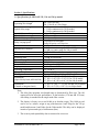
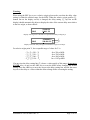
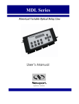
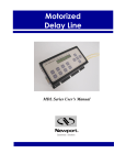
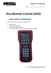
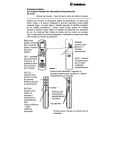
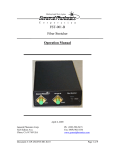
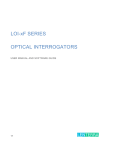
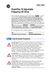
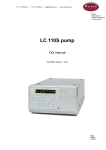
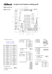
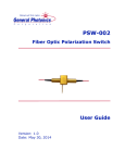
MDL – 002
Miniature Motorized Variable Optical Delay Line
Operation Manual
Version: 1.3
May 15, 2015
General Photonics Corp.
5228 Edison Ave.
Chino, CA 91710 USA
Document #: GP-UM-MDL-002-13
Tel: (909) 590-5473
Fax: (909) 902-5536
www.generalphotonics.com
Page 1 of 23
Table of Contents:
Section 1. Specifications: .................................................................................................. 3
Section 3. Device Description:.......................................................................................... 8
3.1 General Description ................................................................................................. 8
3.2 Polarization Properties .......................................................................................... 12
3.3 Power Supply.......................................................................................................... 12
Section 4. Device Operation:.......................................................................................... 13
4.1. Getting Started....................................................................................................... 13
4.2. Using Operation Panel ......................................................................................... 14
4.3 Remote Operation .................................................................................................. 19
Section 5. Troubleshooting:............................................................................................ 22
Section 6. Technical Support: ........................................................................................ 22
Document #: GP-UM-MDL-002-13
Page 2 of 23
Section 1. Specifications:
1.1 Specifications for MDL-002 250, 330, and 560 ps models
Operating Wavelength1
Optical delay range2
Optical delay resolution
Optical delay accuracy3
Optical delay repeatability3
Delay varying speed4
Insertion loss
Insertion loss variation
PDL
Return loss
Extinction ratio
Optical Damage Power Threshold
Power supply
Control mode
Display
Operating Temperature
Storage Temperature
Fiber type
Dimensions
(Optical delay head, MDL-002-M)
Dimensions
(Control or integrated unit)
SM: 1260-1650 nm
PM: 1310±50 or 1550±50 nm
0 ~ 250 ps continuous for 250 ps model
0 ~ 330 ps continuous for 330 ps model
0 ~ 560 ps continuous for 560 ps model
0.3 µm or 1 fs per encoder count
± 0.01 ps or ±3 µm
± 0.01 ps or ±3 µm
10-speed levels selectable 4
From 0.01 ps/sec. to 256 ps/sec.
1.0 dB nominal
±0.3 dB over entire range for 250 and 330 ps models
±0.5 dB over entire range for 560 ps model
0.1 dB for SM model
50 dB
> 18 dB for PM model
300 mW
12VDC / 1A max.
Panel keypad and RS-232 interface
2 x 16 character LCD
0 °C to 40 °C
-20 °C to 60 °C
Corning SMF-28, or Fujikura PM Panda fiber
0.7” (H) × 1.46” (W) × 4.25” (L) for 250 ps model
0.7” (H) × 1.46” (W) × 5.20” (L) for 330 ps model
0.7” (H) x 1.46” (W) x 6.18” (L) for 560 ps model
1.6” (H) × 4” (W) × 7” (L) for 250 and 330 ps models
1.6” (H) × 4.4” (W) × 8.85” (L) for 560ps model
Note:
1. The delay line operation wavelength range is determined by fiber type. The AR
coating will also affect the performance. A dual window (1310 nm and 1550 nm)
AR coating is standard for the single mode fiber version.
2. The display is factory set to read 0.000 ps at absolute origin. The 0.000 ps read
can be set as a relative origin at any point between 0 and 250ps for the 250 ps
model and between 0 and 560ps for the 560ps model. The delay can be displayed
in units of picoseconds (ps) or millimeters (mm).
3. The accuracy and repeatability data is measured at worst case.
Document #: GP-UM-MDL-002-13
Page 3 of 23
4. The delay change speed levels are as follows:
Speed 0:
Speed 1:
Speed 2:
Speed 3:
Speed 4:
Speed 5:
Speed 6:
Speed 7:
Speed 8:
Speed 9:
0.01
0.25
1
4
8
16
32
64
128
256
ps/second
ps/second
ps/second
ps/second
ps/second
ps/second
ps/second (default setting)
ps/second
ps/second
ps/second
Please note that the speeds in the list above are steady state speeds. There will be
an acceleration and deceleration period at the beginning and the end of the travel.
Document #: GP-UM-MDL-002-13
Page 4 of 23
1.2 MDL-002 1120ps model specifications
Wavelength Range5
Optical Delay Range 6
Optical Delay Resolution
Optical Delay Accuracy
Optical Delay Repeatability
Operation modes
Delay Varying Speed
Insertion Loss
Insertion Loss Variation
Return Loss
PDL
Extinction Ratio
Fiber Type
Optical Connectors
Input Voltage
Control
Display
Operation temperature
Storage temperature
Dimensions
Humidity
SM: 1260 - 1650 nm
PM: 1550±50 nm
0~1120 ps continuous
0.6µm or 2fs per encoder count
± 0.02 ps 7
± 0.02 ps 7
μ-processor embedded system
• Point-to-point operation
• Continuous scan operation
• Remote control operation
10-speed levels selectable 8
From 0.02 ps/sec. to 512 ps/sec.
1.5 dB nominal
± 0.7 dB max. over entire delay range
50 dB
0.1 dB max. for single mode fiber
>18 dB for PM model
SM fiber: SMF-28 standard 9
PM fiber: PANDA PM fiber.10
FC/APC or FC/PC
12V DC/1A (max)
Panel keypad and RS-232 interface
2 × 16 character LCD
0°C to 40°C
-20°C to 60°C
0.7” (H) x 1.46” (W) x 6.18” (L) (optical head)
1.6” (H) × 4.4” (W) × 8.85” (L) (control unit)
Max. 95% non condensing
Notes:
5. The device is optimized at 1550 nm.
6. The display is factory set to read 0.000 ps at absolute origin. The 0.000 ps read
can be set as a relative origin at any point between 0 and 1120ps. The delay can
be displayed in units of picoseconds (ps) or millimeters (mm).
7. The accuracy and repeatability data is measured at worst case.
Document #: GP-UM-MDL-002-13
Page 5 of 23
8. The delay change speed levels are as follows for the MDL-002 1120ps model:
Speed 0:
Speed 1:
Speed 2:
Speed 3:
Speed 4:
Speed 5:
Speed 6:
Speed 7:
Speed 8:
Speed 9:
0.02
0.5
2
8
16
32
64
128
256
512
ps/second
ps/second
ps/second
ps/second
ps/second
ps/second
ps/second (default setting)
ps/second
ps/second
ps/second
Please note that the speeds in the list above are steady state speeds. There will be
an acceleration and deceleration period at the beginning and end of the travel.
9. The SMS-001 input/output coupler should be used with the single mode (nonpolarization maintaining) fiber interfaced MDL-002 1120ps model. For more
information on SMS-001, please contact General Photonics.
10. The PMS-001 input/output coupler should be used with the polarization
maintaining fiber interfaced MDL-002 1120ps model. Please contact General
Photonics for more information on the PMS-001.
Document #: GP-UM-MDL-002-13
Page 6 of 23
Section 2. Overview:
General Photonics’ miniature motorized variable optical delay lines (MDL-002) provide
precise, continuous optical path delay of up to 1120 picoseconds. They are driven by a
DC motor with an integrated encoder, and have an extremely fine delay resolution of
0.3µm, or 1 fs per encoder count for the 250 or 560 ps versions, or 0.6µm (2 fs) per
encoder count for the 1120 ps model. These characteristics make them ideal for precision
optical path length control or timing alignment. As shown in Figure 1, the mini-MDL
consists of a compact optical head (MDL-002-M) and a separate electronic control unit
(MDL-001-C). The optical head is detachable from the control unit for easy integration
into test instruments and medical and telecommunication equipment. Major applications
of these MDL devices include optical time division multiplexing (OTDM), optical
Fourier spectrum analysis, interferometry, pulse alignment, and optical coherence
tomography (OCT). They can also be used to vary the modulation phase of reflections for
the testing of reflection effects on transmitters.
The MDL-002 family consists of 250 ps (7.5 cm), 330 ps (10 cm), 560 ps (17 cm), and
1120 ps (34 cm) optical delay models. Each model can have SM or PM fiber pigtails, or
free space optical beam interfaces for different customer applications.
Figure 1 General Photonics’ miniature motorized variable optical delay line - MDL-002. The optical
head (MDL-002-M) is shown separately, at the top, and attached to the controller unit (MDL-001-C),
at the bottom of the figure.
The control unit contains the microprocessor, keypad, and LCD display panel, along with
a wall-plug power supply adapter. Operation commands and delay parameters can be
keyed in from the keypad, and the status of the device is displayed on the LCD. In
addition, the mini-MDL can be remote controlled by a personal computer via a built-in
RS-232 port. Using popular PC interface software such as LabView (National
Instruments), one can send all commands and read back the device status with the click of
a mouse. Furthermore, the mini-MDL allows arbitrary switching between local and
remote control modes from the keypad and computer.
Document #: GP-UM-MDL-002-13
Page 7 of 23
Section 3. Device Description:
3.1 General Description
The MDL-002 miniature motorized optical variable delay line (mini-MDL) consists of
three sub-modules: the variable optical delay module, electronic controller module, and
operation panel (display/keypad) module. Two package options are available. In the
integrated package, all 3 modules are contained in one enclosure. The optical delay
module can also be packaged in a separate small unit which connects via a ribbon cable
to a controller unit which contains the other two modules. The input/output optical
signals are connected to the variable optical delay module via single mode or polarization
maintaining optical fibers. The electronic controller carries out the control commands,
senses the delay state, and controls a 2-line, 16-character liquid crystal display (LCD).
There are two interfaces for control command input. A built-in RS-232 connector takes
commands from a computer or a hand-held device when the mini-MDL is operating, as
long as the communication between the PC and mini-MDL is established. In manual
control mode the front panel keypad is used to send the corresponding control commands.
Press any key on the keypad to return to manual control from remote control. The delay
status and command information are displayed on the LCD.
3.1.1
MDL-002 package features
Integrated package/controller unit:
Dimensions for the integrated unit or control unit enclosures are shown in Figs. 2-3.
Dimensions are in inches unless otherwise specified.
Figure 2 250 or 330 ps MDL-002 integrated unit/control unit package
Document #: GP-UM-MDL-002-13
Page 8 of 23
Figure 3 560 or 1120ps MDL-002 integrated unit/control unit package
On the left side of the unit are the power switch and either a 16-pin connector for
connection to the optical head (if this is a control unit for a separate optical head) or
input/output fiber pigtails (if this is an integrated package). The RS-232 and DC power
supply connector are mounted on the right side.
The pinout for the 16-pin connector for a control unit is shown in Fig. 4.
2
4
6
8 10 12 14 16
1
3
5
7
9 11 13 15
Figure 4 Pinout for 16-pin connector on mini-MDL separate optical head and control unit.
Document #: GP-UM-MDL-002-13
Page 9 of 23
Table 1 Connector pin assignment list
Pin number
1
2
3
4
5
6
7
8
9
10
11
12
13
14
15
16
Assignment
SENSOR4
SENSOR1
NC
NC
NC
NC
NC
NC
NC
VCC
GND
GND
MOTOR6
MOTOR5
MOTOR2
MOTOR1
Description
Sensor connection
Sensor connection
Not connected
Not connected
Not connected
Not connected
Not connected
Not connected
Not connected
Power supply voltage
Ground
Ground
Encoder output A
Encoder output B
Motor control
Motor control
Separate optical head:
The separate optical head has two optical fiber pigtails to accommodate optical input and
output on the left side of the unit, and a 16-pin connector on the right side for connection
to the control unit. The optical input/output can be single mode, or can be polarization
maintaining (PM) fiber to maintain a linearly polarized input/output state.
The MDL-002 can also be configured for free space optical delay applications. The
input/output apertures are typically ~3 mm in diameter.
Dimensions for the MDL-002 optical heads are shown in Figs. 5-7.
Figure 5 250ps MDL-002 optical head dimensions
Document #: GP-UM-MDL-002-13
Page 10 of 23
Figure 6 330ps MDL-002 optical head dimensions
Figure 7 560 or 1120 ps MDL-002 optical head dimensions
Document #: GP-UM-MDL-002-13
Page 11 of 23
3.2 Polarization Properties
The MDL-002 employs free space optics to adjust optical path length. Therefore, the
polarization state will not change during delay adjustment. However, the standard single
mode input/output fiber(s) may transform the input polarization state to a different state
at the output.
The PM pigtailed MDL can be used for applications requiring high polarization stability.
It is designed for single linear polarization state input aligned at a specified PM fiber axis.
Along this axis, the input linear polarization state will be maintained at the output PM
fiber port. However, if the input polarization state is aligned at 90-degree orientation to
the specified polarization state, the polarization state may be transformed after
propagating through the MDL device. Therefore, it is important to match source
polarization state to the specified PM MDL orientation before operating the device.
Unless specified otherwise, the factory default setting is for slow axis orientation of the
PM fiber.
3.3 Power Supply
All MDL devices require a 12V/1A DC power supply to operate. A standard AC/DC
power supply adapter is shipped with the MDL-002. If the user wants to use his/her own
DC power supply, the DC power supply connector should have correct polarity: the
center pin is positive (+) and the outer contact is negative (-). If a third party DC power
supply is used, it is important to check the power supply output voltage and polarity
before connecting to power line. Incorrect voltage and/or polarity will damage the
control electronics of the MDL-002.
Document #: GP-UM-MDL-002-13
Page 12 of 23
Section 4. Device Operation:
Electrical and optical connections are required during setup of the MDL-002. Follow
safety precautions when making these connections.
4.1. Getting Started
Unpacking
Great care must be taken when unpacking the MDL-002 from its original shipment
package.
Avoid applying any force to optical fiber pigtails, and do not let any free-drop of fiber
connectors occur at any time. Excessive force to fiber pigtails may degrade device
performance or damage the variable optical delay module.
Operation
Follow the steps below to operate the MDL-002 in manual control mode.
1. Check the DC power supply output voltage (12 V DC) and polarity (center
positive).
2. Connect fiber pigtails to the optical path where delay adjustment is to be
performed. The input and output fiber pigtails are interchangeable unless users
specify special connector combinations to match their measurement setups.
For the 1120 ps versions, the input and output travel on the same fiber pigtail. For
an SM 1120 ps MDL-002, connect the MDL’s pigtail to port 2 of the SM
separator. The input should be connected to port 1 of the separator, and the output
to port 3. For a PM 1120 ps MDL-002, connect the MDL’s pigtail to the common
port of the PM separator (PBS). The input and output can be connected to either
of the other two ports.
3. If the MDL has a separate optical head, connect it to the control unit using the
supplied 16-pin connector cable.
4. After power supply connection, turn on the power switch. The red power indicator
LED should light. The LCD will display the model number and initialization
screens (see Section 4.2.3 for display sequence).
5. Follow the operation panel (keypad) instructions (see Section 4.2) to enter
commands.
Document #: GP-UM-MDL-002-13
Page 13 of 23
4.2. Using Operation Panel
The operation panel of the control unit is shown in Figure 8.
Motorized Delay Line
ORG
STOP
SCAN
SPD
PS/
mm
MDL-002
120.000 PS
50.000 PS
ORG
ABS
+/–
REL
Volts
Enter
CH1
Figure 8 Control unit front panel.
4.2.1 LCD
The LCD displays the delay time, system status, and commands.
4.2.2 Command Keys
There are 13 keys available on the panel for command input and status setting. The
functions of these keys are described as follows:
(1). ABS
The ABS key is used to set a single delay value, relative to the current origin (0 point). If
the current origin is at 0 ps (default setting), then the delay value displayed in the first
line of the LCD is the absolute delay defined by the MDL-002’s internal position sensor.
When ABS is pressed, a cursor will appear in the delay value in the first line of the LCD.
The arrow keys can then be used to set the desired delay value. Once the delay value is
set, pressing ENTER causes the MDL to execute the delay setting.
(2). ORG
When ORG is pressed, the MDL-002 performs a sensor position check routine and then
resets the delay to the absolute zero point defined by the internal position sensor. It also
resets the origin point to its default value of 0.000 ps. This is the same initialization
process that it performs when it is first powered on. The ORG key can be pressed any
time that the motor is not moving. The buzzer will sound when the absolute zero point is
reached. The display when this process is finished will be:
ORG
Document #: GP-UM-MDL-002-13
0.000 ps
0.000 ps
Page 14 of 23
(3). SCAN
The SCAN key is used to enter scan setup mode and to set the scan start and end points.
When the SCAN key is pressed once, the first line of the LCD displays “SC1 0.000”.
This is the setup screen for the scan start point (SC1). Pressing the SCAN key repeatedly
will toggle the display between the start (SC1) and end point (SC2) setup screens. Use the
arrow keys to set the desired start/end point. The left and right arrow keys move the
cursor position, and the up and down keys increment the selected digit. After the start and
end points are set, pressing the ENTER key will start the scan; the MDL-002 will
continuously scan back and forth between the two set points. Press the STOP key to stop
the scan and display the current delay time on the LCD. In scanning mode, only the
STOP key is functional. The scan must be stopped before any other settings can be
changed.
Note: After 30 minutes of continuous scanning, the MDL-002 will enter standby mode
and stop scanning. This is a safety feature to prevent excessive heat generation from
prolonged mechanical motion. To restart continuous scanning with the currently set scan
parameters, press SCAN and then ENTER.
(4). STOP
This key is used to stop the motor when it is in motion. When the MDL is scanning,
STOP is used to stop the scan. In addition, STOP can be used to stop the implementation
of a single delay setting. For example, if a long delay and a slow speed are selected, it can
take a long time to reach the final state. The STOP key can be used to stop the motor
movement before the final state is reached. The LCD will display the current delay
position at the time STOP was pressed.
(5). SPD
The SPD key is used to set the delay changing speed. There are 10 speeds available for
selection. For all models except the 1120 ps model, the speeds are:
SPD0 (Speed 0):
SPD1 (Speed 1):
SPD2 (Speed 2):
SPD3 (Speed 3):
SPD4 (Speed 4):
SPD5 (Speed 5):
SPD6 (Speed 6):
SPD7 (Speed 7):
SPD8 (Speed 8):
SPD9 (Speed 9):
Document #: GP-UM-MDL-002-13
0.01
0.25
1
4
8
16
32
64
128
256
ps/second
ps/second
ps/second
ps/second
ps/second
ps/second
ps/second (default)
ps/second
ps/second
ps/second
Page 15 of 23
For the 1120 ps model, the speeds are:
SPD0 (Speed 0):
SPD1 (Speed 1):
SPD2 (Speed 2):
SPD3 (Speed 3):
SPD4 (Speed 4):
SPD5 (Speed 5):
SPD6 (Speed 6):
SPD7 (Speed 7):
SPD8 (Speed 8):
SPD9 (Speed 9):
0.02
0.5
2
8
16
32
64
128
256
512
ps/second
ps/second
ps/second
ps/second
ps/second
ps/second
ps/second (default setting)
ps/second
ps/second
ps/second
When the SPD key is pressed, the top line of the LCD displays “SPD6 32ps/s” (default
setting for most MDL-002 models). Use the UP and DOWN keys to change the speed to
the desired value. Press ENTER to accept the speed setting.
(6). ps/mm
The ps/mm key is used to set the delay unit. It toggles the display between ps
(picoseconds) and mm (millimeters). The default is ps.
(7). REL
The REL key puts the MDL-002 into relative delay mode. In this mode, a zero offset
function allows the user to set the origin (ORG) to any delay time setting within the total
delay limit. The current delay value (top line of LCD) is then displayed relative to the
new origin. For example, if the display initially shows:
ORG
90.000 PS
0.000 PS
with the origin (ORG) at its default position of 0.000 ps, then when REL is pressed, the
cursor moves to the second line:
ORG
90.000 PS
0.000 PS
The arrow keys can now be used to set the relative origin point. For example, if ORG is
set to 50.000 ps, the current delay (first line) will automatically change to 40.000 ps (90 –
50).
(8). +/In relative delay time setting mode, the delay range includes values that can be negative
or positive, relative to the new origin. For example, if the relative origin is set at 125 ps,
then the total delay range for a 250 ps MDL, relative to 125 ps, is now –125 to 125 ps.
Document #: GP-UM-MDL-002-13
Page 16 of 23
Now, when a (relative) delay time of 50 ps (corresponding to an actual delay of 175 ps) is
entered, the LCD should display:
50.000 PS
125.000PS
ORG
The +/- key is used to set the sign of the entered delay value. For example:
– 50.000PS
125.000PS
ORG
The actual delay value corresponding to the set value is now 75 ps (125 – 50).
If the ORG is set to 0.000 or the set delay is outside the allowed delay range, the device
will not respond to the +/- key.
(9-10). UP and Down (arrow) keys
The UP and DOWN (▲ and ▼) arrow keys are used to change the currently selected
digit (indicated by the cursor) during parameter setting (ex. delay time, origin).
(11-12). LEFT and RIGHT (arrow) keys
The LEFT and RIGHT (◄ and ►) arrow keys are used to move the cursor position.
(13). ENTER
The ENTER key executes a command or setting. For example, after a delay time is set,
pressing ENTER causes the motor to move to a position corresponding to the set delay.
The time needed to reach the final delay state depends on the delay value and selected
speed. In scan mode, ENTER starts the scan.
4.2.3. Panel Operation Examples
(1). Set delay time to 100.5 ps with the origin (ORG) at (absolute) 0.000 ps.
Turn on the power switch. The buzzer will sound and the LCD will display:
MDL-002 XXX ps
Initializing…
After initialization, the LCD will display:
ORG
Document #: GP-UM-MDL-002-13
0.000
0.000
ps
ps
Page 17 of 23
The underline indicates the cursor position. The top line shows the current delay state as
0 ps. The origin is also at its absolute (nonrelative) position at 0 ps. At this point, if the
REL key is pressed, the LCD display changes to:
ORG
0.000
0.000
ps
ps
with the cursor now in the second line to allow a relative origin point to be set. If the
ABS key is pressed, the cursor returns to the first line for delay state setting. To set the
delay to 100.5 ps for this example, use the left and right arrow keys to move the cursor
position and the up and down arrow keys to change the selected digit. The display will
show:
ORG
100.500
0.000
ps
ps
Press the ENTER key to execute the delay setting.
(2). Set delay time to -100 ps with the relative origin (ORG) at 120ps (i.e., the
absolute delay value is 20 ps).
Press REL key. The LCD displays:
ORG
0.000
0.000
ps
ps
The cursor will blink in the second line. Use the arrow keys to change the ORG setting to
120.000 ps (left and right arrow keys to move the cursor and up and down arrow keys to
change the value of the selected digit). The display will show:
ORG
–120.000
120.000
ps
ps
The first line delay value automatically changes to –120.000ps to indicate the current
delay position (0 ps absolute delay) relative to the new origin position.
Press the ABS key to change from relative 0 point setting mode to delay time setting. Use
the arrow keys to change the delay time to -100.000 ps. The LCD displays:
ORG
– 100.000 ps
120.000 ps
Press ENTER key to execute the new delay setting.
Document #: GP-UM-MDL-002-13
Page 18 of 23
(3). Scan function
Set the scan speed: Press the SPD key to display the speed setting. Use UP or DOWN
arrow keys to select a speed setting. The default speed setting is 32ps/second for most
MDL-002 models. The LCD displays:
ORG
SPD6:
0.000
32ps/s
ps
Then press the SCAN key. The display will change to the scan start point setup window:
SC1
ORG
0.000
0.000
ps
ps
Use the arrow keys to set the scan start position SC1 (left and right arrow keys to move
the cursor and up and down arrow keys to change the value of the selected digit). After
setting SC1, press SCAN again. The display changes to the scan end point setup screen:
SC2
ORG
0.000
0.000
ps
ps
The end position SC2 can be set similarly using the arrow keys. After setting the start
and end positions, press the ENTER key to start the scan. The MDL will continuously
scan back and forth between the two set points until the STOP key is pressed, or until it
enters standby mode.
4.3 Remote Operation
The MDL-002 can be remote controlled by a personal computer (PC) via a built-in RS232 communication port. To establish remote control, the user needs to use a straight
connection RS-232 cable to connect the computer RS-232 Serial Port to that on the MDL
control unit.
When the control unit is powered on, the LCD will display:
ORG
0.000
0.000
ps
ps
This is local control (panel control) mode. If an RS-232 command comes from the
computer, the MDL will switch to remote control mode automatically, and the remote
control signifier “R” will appear in the first position of the first line of the display. The
LCD now shows:
R
ORG
0.000
0.000
Document #: GP-UM-MDL-002-13
ps
ps
Page 19 of 23
Many programming languages for PCs support serial communications, including Visual
Basic, LabVIEW and C. Any such program can be used to send ASCII string commands
to the MDL through the RS-232 port. Microsoft Windows’ Hyper Terminal can be used
to
perform
an
RS-232
remote
control
test.
The
path
is
Programs/Accessories/Communications/HyperTerminal.
To perform computer remote control, use the following procedure:
1. Turn on MDL control unit power switch;
2. Launch any serial port communication program;
3. Send a command from the Remote Control Command List. The command
sequence should be sent one command at a time. The MDL response signal
should be checked before sending the next command (see Section 4.3.1, Remote
Control Command List).
To return to manual control mode, press ABS, REL, SCAN, ENTER, ORG, ps/mm, or
SPD on the operation panel. If the MDL is scanning in remote mode, the user must stop
the scan by using a remote command or the STOP key on the panel before pressing any
of these other keys. If the STOP key is pressed, the MDL will return to panel control.
4.3.1
Remote Control Command List
The ASCII commands for MDL remote control are summarized in Table 2.
Command
_ABS_ *$ or
_abs_ *$
_REL_ *$ or
_rel_ *$
_SC1_ *$ or
_sc1_ *$
_SC2_ *$ or
_sc2_ *$
_SPD_*$ or
_spd_$
Table 2
Remote control ASCII commands
Description
Example
Set the delay time
_ABS_ 1.2$
* is the delay time, range 0~250ps
_abs_ -23.456$
for 250 ps model
_REL_100$
Relative zero position set
_rel_20$
_SC1_10$
Scan start position
_se1_10$
_SC2_100$
Scan end position
_sc2_100$
Scan speed setting
* is the speed number, range 0~9
_SPD_0$
See p. 15-16 for corresponding
_spd_1$
speeds
_ORG_$ or
_org_$
Reset to absolute zero position.
_SST_$ or
_sst_$
Start scan
Note: Scan will time out after 30
minutes continuous operation
_STP_$ or
_stp_$
Stop motor motion
Document #: GP-UM-MDL-002-13
Page 20 of 23
_MMU_$ or
_mmu_$
_PSU_$ or
_psu_$
Set delay unit to mm
Set delay unit to ps
Remote Control Command notes:
1. RS-232 commands are case sensitive ASCII codes. The last character of each
command ASCII string, $, is an end mark.
2. RS-232 port uses asynchronous framing, 8 data bits, no parity bit, and 1 stop bit.
3. RS-232 data rate: 9600 bps.
4. Only one command is allowed in each command string. Wait for “OK” response
from MDL device before sending the next command.
5. If MDL is scanning (the motor is moving), only the stop command will be
received. Any other commands will receive a “NO” response.
The MDL will respond to the computer with an “OK” string when a command string is
accepted. Any additional commands sent before the “OK” string is returned will be
ignored by the MDL, except the stop command “_stp_$” or “_STP_$”. If the format of
the command sent to the MDL is wrong, or input data is out of the allowed data range, for
example: “aBS_ 123.456$” (no “-”), “_ABS_ 123.456$” (space is not permitted),
“_ABS_123.456” (no $ sign), or “_ABS_2723.456$” (delay data out of range), the MDL
will respond with a “NO” string. In user interface programs, please check the OK string
before sending the next command unless sending the stop command, “_stp_$” or
“_STP_$”. Please note that if the motor is moving, it must be stopped before changing
other settings.
Document #: GP-UM-MDL-002-13
Page 21 of 23
Section 5. Troubleshooting:
The MDL-002 may display one of 3 error codes on the control panel to indicate
problems.
Err Power Off
Err1 Power Off
Err2 Power Off:
Optical head not moving
Motor not turning
Optical head not sensed by control module.
Any error message indicates a mechanical or optical head feedback error.
“Err Power Off” and “Err1 Power Off” are related to mechanical and motor problems. If
either of these messages appear, power off the MDL and check that the electrical
connector is securely connected. Power on the MDL. If the error message persists,
contact General Photonics..
“Err2 Power Off” is related to cable or sensor problems. Typically, the error is caused by
poor connection of the sensor ribbon cable. Power down the MDL, verify the ribbon
cable connection, and power the MDL back on. If the error message persists, contact
General Photonics.
Section 6. Technical Support:
General Photonics is committed to high quality standards and customer satisfaction. For
any questions regarding the quality and use of the MDL-002, or future suggestions,
please contact General Photonics Corporation at (909)-590-5473 (telephone) or (909)902-5536 (fax), or by e-mail at [email protected]. General Photonics will
respond to all customer questions within 24 hours during regular business hours. General
Photonics can also be contacted by mail at:
General Photonics
5228 Edison Avenue
Chino, California 91710
USA
Document #: GP-UM-MDL-002-13
Page 22 of 23
Warning:
When using the REF key to set a relative origin, please make sure that the delay value
setting is within the allowed range for the MDL. When the relative origin position (T2,
bottom line on the display screen) is changed, the delay setting (T1, top line on the
display) should automatically adjust to display the value of the current delay state relative
to the new origin, as shown below.
ORG
50.000 PS
0.000 PS
Display with origin set at absolute zero position and delay setting 50 ps.
ORG
-450.000 PS
500.000 PS
T1
T2
Display with same delay setting, but with relative origin set at 500 ps.
For relative origin point T2, the acceptable range of values for T1 is
– T2 ≤ T1≤ 250 – T2
– T2 ≤ T1≤ 330 – T2
– T2 ≤ T1≤ 560 – T2
– T2 ≤ T1≤ 1120 – T2
for a 250 ps MDL
for a 330 ps MDL
for a 560 ps MDL
for a 1120 ps MDL
If at any time the delay setting line (T1) shows a value outside of this range, do not press
ENTER. Also, do not use the ORG key to reset the MDL before changing the invalid
setting. Press the ABS key to move the cursor to the delay setting line, and use the arrow
keys to set the delay to a value within the allowed range before executing the setting.
Document #: GP-UM-MDL-002-13
Page 23 of 23