1
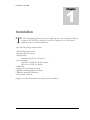
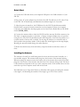
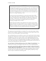
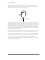
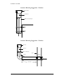
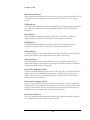
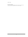
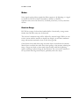
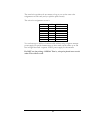
BOLTEK CORPORATION Lightning Detection LD-350 Lightning Detector Installation/Operators Guide SEE DISCLAIMER ON REVERSE BOLTEK LIGHTNING DETECTION LD-350 Lightning Detector Disclaimer LD-350 lightning data is only approximate and should not be used for safety applications. Strike and storm locations indicated and alarm statuses may be erroneous and should not be used to safeguard personnel, equipment or data. Neither Boltek Corporation nor its affiliates shall be liable to the purchaser of this product or third parties for damages, losses, costs, or expenses incurred by purchaser or third parties as a result of use, misuse, accident, or abuse. Notwithstanding the above Boltek Corp’s liability shall not exceed the purchase price of the equipment. THIS EQUIPMENT IS NOT TO BE USED FOR SAFETY PURPOSES 2000-2011 Boltek Corporation Boltek Corporation 2316 Delaware Ave PMB 254 Buffalo, NY 14216 USA 210 Glendale Ave Suite 168 St. Catharines, ON L2T3Y6 Canada Email: [email protected] Web: www.boltek.com Phone (905) 734-8045 • Fax (905) 734-9049 FCC Compliance Statement For United States Users This equipment is tested and found to comply with the limits for a Class B digital device, pursuant to Part 15 of the FCC Rules. These limits are designed to provide reasonable protection against harmful interference in a residential installation. This equipment generates, uses, and can radiate radio frequency energy and, if not installed and used in accordance with the instructions, may cause harmful interference to radio or television reception. However, there is no guarantee that interference will not occur in a particular installation. If this equipment does cause interference to radio and television reception, which can be determined by turning the equipment on and off, the user is encouraged to try to correct the interference by one or more of the following measures. Reorient or relocate the receiving antenna. Increase the separation between the equipment and the receiver. Connect the equipment into an outlet on a circuit different from that to which the receiver is connected. Consult the dealer or an experienced radio/TV technician for help. WARNING The connection of a non-shielded equipment interface cable to this equipment will invalidate the FCC Certification of this device and may cause interference levels which exceed the limits established by the FCC for this equipment. It is the responsibility of the user to use a shielded interface cable with this device. If this equipment has more than one interface connector, do not leave cables connected to unused interfaces. Changes or modifications not expressly approved by the manufacturer could void the user’s authority to operate the equipment. For Canadian Users This Class B digital apparatus meets all requirements of the Canadian Interference-Causing Equipment Regulations. Cet appareil numérique de la class B respecte toutes les exigences du Règlement sur le materiel brouilleur du Canada. Table of Contents Installation ................................................................................................................................. 1 Quick Start ......................................................................................................................... 2 Installing the Antenna ............................................................................................................... 2 USB Drivers........................................................................................................................ 8 Operation ................................................................................................................................... 9 Stand-Alone Operation ............................................................................................................. 9 Front Panel Controls................................................................................................................ 9 Noise ...................................................................................................................................... 12 Receiver Range ...................................................................................................................... 12 USB Commands and Messages ............................................................................................... 13 Commands ....................................................................................................................... 13 USB Messages................................................................................................................ 14 Making an Antenna Cable....................................................................................................... 15 I N S T A L L A T I O N 1 Chapter Installation T he LD-350 Lightning Detector puts a live lightning map on your laptop or desktop computer. The LD-350 is suitable for use with a computer or as a stand-alone lightning detector for fixed installations. Your LD-350 package should contain: 1 LD-350 lightning detector 1 lightning detector antenna 1 antenna cable, standard length 50 feet (15 meters) 1 AC wall adapter, 120VAC to 12VDC for North America, 220VAC to 12VDC for Europe 1 USB cable 4 rubber feet for desktop mounting CDROM containing Windows software CDROM containing USB drivers 1 user manual (this is it) Unpack your LD-350 and make sure all the parts are included. 1 I N S T A L L A T I O N Quick Start 1) Connect the USB cable from your computer USB port to the USB connector of your LD-350. 2) Plug in the AC power adapter into the lead of the LD-350 and into an AC outlet. Turn on the LD-350. It should beep and illuminate the indicator lights for 2 seconds. 3) After the power is turned on, the USB drivers for the LD-350 should automatically install if there is an active internet connection on the computer. If there is no internet connection, the USB driver install program can be found on the Boltek Driver CD-ROM under:\LD350_USB\. 4) Connect the antenna cable to both the LD-350 and the antenna. Hold the antenna a few feet from a computer monitor or television. (A laptop computer display may not produce enough noise.) The LD-350 should detect the radio frequency noise from the monitor as a constant stream of noises and/or strikes. By moving the antenna you should be able to find a position that produces strikes. Yellow strike dots should appear on the map display. Rotating the antenna should change the strike direction. 5) Mount the antenna away from televisions, computer monitors and other sources of noise. Installing the Antenna The antenna is housed in a small black plastic box that must be mounted vertically on a non-metallic support. The antenna cable plugs into the bottom of the antenna housing. When mounting the antenna ensure the correct side of the antenna faces north. The cable plugs into the bottom of the antenna with the front of the antenna facing north. The front of the antenna corresponds to the top of the computer screen. If the antenna does not face north the top of the computer screen will not be north. Provided there are no large metal objects to block the radio signals, mounting the antenna 6 feet high is ok. Mounting the antenna 12 feet high is good. 20-25 feet is better. 2 I N S T A L L A T I O N LIGHTNING Receiving lightning signals does not cause lightning to strike. Your LD-350 antenna is less likely to be struck by lightning than your anemometer, since the antenna does not need to be above the roof line. Still though you must exercise common sense when choosing a location for your antenna. If you mount the antenna on a ten foot pole on the highest point on your roof, with no trees or television tower nearby you are asking for lightning to strike. Your best protection against lightning is to mount the antenna indoors. Radio waves will pass right through a wood building. Lightning is more likely to strike a tall tree, television antenna, copper plumbing vent, satellite dish, telephone line, power lines, or CB antenna. If you do mount the antenna outdoors make sure there are plenty of ground paths for lightning nearby (such as those just mentioned), and higher than the antenna. The LD-350 receiver board has surge suppression in its input to protect against voltages induced into the antenna cable. It is also a good idea to purchase a surge suppressor to plug your computer into. If you have a modem try to find one that will protect your phone line as well. Lightning often enters through the telephone line. Both your computer and surge suppressor will need to be grounded. The antenna may be mounted indoors or outdoors. Try to mount the antenna as high as possible (without making it a lightning rod). Mounting the antenna high will keep it away from noise sources and will improve the maximum range. In a wood framed house, the second floor or attic is often a good location for the antenna. This places the antenna above the most common sources of interference: televisions, lights and appliances, yet leaves it in a good location to receive lightning signals. Mount the antenna to the drywall or attic rafter away from screws, nails, electrical wiring, and other metal objects. If your house has aluminum siding (vinyl siding is ok), foil-lined insulation, or any other metal coating, you might have problems receiving with the antenna indoors, as the metal may shield radio waves from the antenna. DO NOT MOUNT THE ANTENNA SO AS TO ATTRACT LIGHTNING. The antenna does not need to be the highest object in the area to receive lightning signals. DO NOT LOCATE THE ANTENNA NEAR AN OBJECT WHICH IS LIKELY TO BE STRUCK BY LIGHTNING. Objects such as television antennas, CB antennas, power lines, phone lines and tall trees are natural targets for lightning. Keep the antenna and cable away from anything which might be struck by lightning. Lightning can jump from one object to another in its search for ground. 3 I N S T A L L A T I O N The antenna may be mounted with nylon cable ties, or with nylon bolts through the mounting flanges (available at a hardware store). Do not use steel screws to mount your antenna, as the antenna must not be near any metal objects. Antenna North Antenna Cable If mounting the antenna outdoors, care must be taken to protect the antenna connector from moisture. While the antenna is completely waterproof the antenna connector must be sheltered from rain. Place the antenna inside a non-metal housing such as a length of ABS or PVC pipe with an end cap covering the top. Keep a small opening on the bottom to allow condensation to drain out. ABS or PVC pipe, fittings and glue may be purchased from a hardware store plumbing department. Mark NORTH on the outside of the pipe to help in orienting the antenna correctly. Fasten the cable to the wall or support about 6-12" below the antenna. Leave a bit of slack in the cable near the antenna so that there is no strain on the connector from the wire. If you find the 50' antenna cable provided is not long enough you may purchase a Boltek 50' extension cable. This allows you to locate the antenna up to 100' from your computer. You may also purchase a replacement cable at any computer store selling network hardware. Any Category 5 cable up to 200 feet will work. See Appendix C for information on making your own antenna cable. 4 I N S T A L L A T I O N Antenna Mounting Suggestion - Outdoor End Cap Antenna AB S or PVC Pi pe Antenna Mounting Suggestion - Outdoor End Cap Antenna AB S or PVC Pipe Tower Clamps Elbow At leas t 36" 5 I N S T A L L A T I O N Antenna Mounting Suggestion - Attic An te n n a Antenna Mounting Examples Here an antenna is mounted in an attic. PVC plumbing hardware is used to attach the antenna to the framing. The vertical pipe is not cemented to allow the antenna to be rotated slightly for fine-tuning direction. The front of the antenna must face exactly north. 6 I N S T A L L A T I O N Here an antenna is mounted in a shed using PVC plumbing hardware purchased at a local hardware store. The antenna is attached using nylon cable ties. Here the antenna is attached to the drywall in the second floor bedroom of a house. The antenna is mounted on the wall using PVC plumbing hardware purchased at a local hardware store. The antenna is attached to the PVC pipe with nylon screws. The vertical piece of PVC pipe is not cemented so that the antenna can be rotated to fine-tune the direction. Mount the antenna between studs to keep it away from nails and screws. Look for electrical outlets on the wall to determine if there is wiring behind the drywall. Keep the antenna away from electrical wiring, to reduce the chance of picking up noise. 7 I N S T A L L A T I O N Here the antenna is mounted to the side of a pole using ABS sewer pipe. USB Drivers The USB drivers will create two USB controllers for your computer. Once the cable and drivers are installed on your computer the extra controllers will show up on your System Device Manager as LD-350 Lightning Detector A & LD-350 Lightning Detector B. Installing the LD-350 USB Device Drivers: With your computer and LD-350 turned on, plug the USB adapter cable into a spare USB port on your computer or hub. USB devices may be plugged and unplugged with the power on. Windows will detect the new device and will automatically install the device drivers if you have an active internet connection. 8 2 Chapter O P E R A T I O N Operation Stand-Alone Operation The LD-350 can also be used as a stand-alone lightning detector without the need of a computer. The indicators, and internal beeper can be monitored when storms approach to determine lightning approaching. It can initially be connected to a computer to change the default alarm values, and squelch level if they aren't suitable. If the optional LTS-3 timestamp card is installed on the LD-350, then it can also operate and transmit data to the Lightning Network if there is an available Network connection without the need of a computer. Front Panel Controls Main Power Button The main power button disconnects 12V power from the LD-350, the antenna, the USB connector, and the LTS-3 connector (if option installed) on the rear of the LD-350. 9 O P E R A T I O N Main Power Indicator The power indicator illuminates to indicate 12V power is present at the LD-350. If the indicator does not light when the unit is turned on check your 12V power source. USB Indicator The USB indicator illuminates when the USB cable is connected from the LD-350 to a computer, and flashes as data is transmitted between the LD-350 and the computer. Net Indicator The Net indicator illuminates when the LD-350 is connected to the Boltek Lightning Network with the optional LTS-3 timestamp card installed. GPS Indicator The GPS indicator illuminates when the optional LTS-3 timestamp card is installed, and the LD-350 is connected to a Timestamp GPS receiver. Strike Indicator The Strike Indicator emits a short flash when a lightning strike is detected. If the Strike Tone Button is pressed the detector also emits a short beep. Noise Indicator The Strike Indicator emits a short flash when a noise signal is detected. If the Strike Tone Button is pressed and Noise Beeps have been turned on in software the detector will also emits a short beep. Noise & Strike Beeper Switch The Noise & Strike Beeper Switch located on the right side of the Strike indicator when pushed in, will enable the internal beeper to sound a short beep when a strike or noise is detected. The internal beeper is disabled for noise and strikes when the button is pushed out. Close & Severe Beeper Switch The Close & Severe Beeper Switch located on the left side of the Close indicator when pushed in, will enable the internal beeper to sound a long beep when either the Close Storm alarm or Severe Storm alarm is activated. The internal beeper is disabled for the two alarms when the button is pushed out. Close Storm Indicator The Close Storm Indicator illuminates when a strike signal is detected within the user specified close storm range set in the software. 10 O P E R A T I O N Severe Storm Indicator The Severe Storm Indicator illuminates when the strikes per minute that are detected exceed the rate specified by the user set in the software. 11 O P E R A T I O N Noise Noise signals can be either a signal that did not appear to be lightning, or a signal for which the LD-350 could not determine a distance or direction. Operation noise can come from noisy overhead power lines, or noisy electronic devices. Receiver Range LD-350 has a range of about three hundred miles. Occasionally, strong storms farther than 300 miles away may be detected. The receiver’s maximum range will be affected by antenna height. While you can receive storms with the antenna at virtually any height, you will have maximum range with antenna mounted at least 25 feet above ground. Other factors that could affect range are metal objects located near the antenna. Metal objects can block the radio waves from getting to the antenna, reducing the range. A large steel shed or other metal object nearby could block lightning signals, resulting in reduced range in that direction. Try to mount the antenna as far as possible from large metal objects, preferably above the object. 12 U S B C O M MA N D S A N D M E S S A G E S A Appendix USB Commands and Messages Commands SQ<cr> : query squelch level SQ<value 0-100><cr> : set squelch level CAD<cr> : query close alarm distance CAD<distance 0-250><cr> : set close alarm distance CAT<cr> : query close alarm time CAT<distance 0-250><cr> : set close alarm time SAR<cr> : query severe alarm rate SAR<0-999><cr> : set severe alarm rate SAT<cr> : query severe alarm rate SAT<0-999><cr> : set severe alarm rate 13 U S B C O M MA N D S A N D M E S S A G E S USB Messages Strike Sentence $WIMLI,<ddd>,<uuu>,<bbb.b>*<cs><cr><lf> <ddd> - corrected strike distance 0-300 miles <uuu> - uncorrected strike distance 0-300 miles <bbb.b> - bearing to strike 000.0-359.9 degrees <cs> - checksum in hex <cr> - carriage return <lf> - line feed Noise Sentence $WIMLN*<cs><cr><lf> <cs> - checksum in hex <cr> - carriage return <lf> - line feed Status Sentence $WIMSU,<ccc>,<sss>,<ca>,<sa>,<ldns1>,<ldns2>,*<cs><cr><lf> <ccc> - close strike rate 0-999 strikes/minute <sss> - total strike rate 0-999 strikes/minute <ca> - close alarm status (0: not active, 1: active) <sa> - severe alarm status (0: not active, 1: active) <ldns1> - lightning network 1 connection state <ldns2> - lightning network 2 connection state <cs> - checksum in hex <cr> - carriage return <lf> - line feed 14 B Appendix Making an Antenna Cable The LD-350 uses standard Category 5 (Cat5) 10baseT network cable for the antenna cable. You can purchase a replacement antenna cable from any computer store selling network hardware. Antenna cables may be up to 200 feet long. If you have access to a crimper for RJ-45 connectors and a source of RJ-45 connectors and Category 5 network cable you can make your own custom antenna cable. Making your own cable means you are able to pull the cable through conduits, walls, etc. before you attach the connectors. This lets you drill smaller holes for the cable and protects the connectors from damage during installation. If you make your own antenna cable you must ensure that the wire pairing is done correctly. The connectors must not only be wired straight through (non-reversing), but the twisted pairs must be located in the correct positions. If the pairing is not done correctly there will be crosstalk between the different signals on the cable and your unit will not work properly. The correct pair locations are: Wire position 12345678 Pair 33211244 What this means is: one pair is in the center (positions 4&5), another pair is split and surrounds the first (positions 3&6), another pair is on the left (positions 1&2) and another pair is on the right (positions 7&8). 15 The actual color positions do not matter as long as you use the same color assignments on both ends, and you split the pairs correctly. The wire color assignments we use is POSITION 1 2 3 4 5 6 7 8 PAIR 3 3 2 1 1 2 4 4 COLOR White/Green Green White/Orange Blue White/Blue Orange White/Brown Brown You can have up to 200 feet of antenna cable without using a separate antenna power supply. In special circumstances we have made custom cables up to 500 feet in length that used a separate 12VDC power supply for the antenna. Do NOT use the pairing: 11223344. That is, wire pairs placed next to each other. This will not work. 16