1
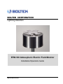
BOLTEK CORPORATION Lightning Detection EFM-100 Atmospheric Electric Field Monitor Installation/Operators Guide EFM100-1000120-101812 BOLTEK LIGHTNING DETECTION EFM-100 Atmospheric Electric Field Monitor Disclaimer EFM-100 lightning data is only approximate and should not be used for safety applications. Strike and storm locations indicated and alarm statuses may be erroneous and should not be used to safeguard personnel, equipment or data. Neither Boltek Corporation nor its affiliates shall be liable to the purchaser of this product or third parties for damages, losses, costs, or expenses incurred by purchaser or third parties as a result of use, misuse, accident, or abuse. Notwithstanding the above Boltek Corp’s liability shall not exceed the purchase price of the equipment. THIS EQUIPMENT IS NOT TO BE USED FOR SAFETY PURPOSES USE OF THIS PRODUCT SHALL BE DEEMED TO BE ACCEPTANCE OF BOLTEK’S STANDARD TERMS AND CONDITIONS (ENCLOSED AND AVAILABLE AT WWW.BOLTEK.COM). IF YOU DO NOT AGREE TO BE BOUND BY THESE TERMS AND CONDITIONS PLEASE RETURN THIS PRODUCT TO THE PLACE OF PURCHASE FOR A FULL REFUND. 2004-2014 Boltek Corporation 4 Stonebridge Dr. Unit 2 Port Colborne, ON. L3K 5V5 Canada Email: [email protected] Web: www.boltek.com Phone (905) 734-8045 • Fax (905) 734-9049 FCC Compliance Statement For United States Users This equipment is tested and found to comply with the limits for a Class B digital device, pursuant to Part 15 of the FCC Rules. These limits are designed to provide reasonable protection against harmful interference in a residential installation. This equipment generates, uses, and can radiate radio frequency energy and, if not installed and used in accordance with the instructions, may cause harmful interference to radio or television reception. However, there is no guarantee that interference will not occur in a particular installation. If this equipment does cause interference to radio and television reception, which can be determined by turning the equipment on and off, the user is encouraged to try to correct the interference by one or more of the following measures. Reorient or relocate the receiving antenna. Increase the separation between the equipment and the receiver. Connect the equipment into an outlet on a circuit different from that to which the receiver is connected. Consult the dealer or an experienced radio/TV technician for help. WARNING The connection of a non-shielded equipment interface cable to this equipment will invalidate the FCC Certification of this device and may cause interference levels which exceed the limits established by the FCC for this equipment. It is the responsibility of the user to use a shielded interface cable with this device. If this equipment has more than one interface connector, do not leave cables connected to unused interfaces. Changes or modifications not expressly approved by the manufacturer could void the user’s authority to operate the equipment. For Canadian Users This Class B digital apparatus meets all requirements of the Canadian Interference-Causing Equipment Regulations. Cet appareil numérique de la class B respecte toutes les exigences du Règlement sur le materiel brouilleur du Canada. CAUTIONS EFM-100 lightning data is only approximate and should not be used for safety applications. Strike and storm locations indicated and alarm statuses may be erroneous and should not be used to safeguard personnel, equipment or data. Install the EFM-100 Field Mill on a calm clear day when no thunderstorms are expected. If you are not experienced in safe antenna installation using appropriate safety equipment you should refer installation to an experienced antenna installer. (See Television Antennas in the Yellow Pages) LIGHTNING HAZARD EPM-1 connections are not optically isolated from the roof mounted field mill. Dangerous voltages may occur should lightning strike at or near the field mill. IMPORTANT The EFM-100 field mill needs to be grounded for proper operation and for lightning and electrical safety. Connect the field mill green ground wire and the field mill mounting hardware to your building central ground through a suitable sized grounding wire according to your local electrical code. ELECTROCUTION HAZARD You can be killed if the field mill or its mounting hardware comes in contact with an electrical power line. WATCH FOR AND STAY AWAY FROM ALL OVERHEAD WIRES. Table of Contents INTRODUCTION .......................................................................................................1 THEORY OF OPERATION.................................................................................................2 INSTALLATION .........................................................................................................5 EFM-100 DISPLAY SOFTWARE INSTALLATION .............................................................6 EFA-20 USB DRIVER INSTALLATION ...........................................................................6 HARDWARE INSTALLATION ............................................................................................7 CHOOSING AN OUTDOOR MOUNTING LOCATION ...........................................................7 EPM-1 POWER MODULE ................................................................................................9 ANALOG OUTPUT ......................................................................................................... 10 EFA-10 FIBER OPTIC ADAPTER .................................................................................. 11 EFA-20 FIBER OPTIC ADAPTER .................................................................................. 11 ST FIBER OPTIC CONNECTORS ................................................................................... 12 CALCULATING A PRECISE SENSITIVITY VALUE ........................................................... 14 GROUNDING DETAIL .................................................................................................... 16 CONFIGURING THE SOFTWARE......................................................................... 19 EFM OPTIONS: GENERAL ............................................................................................ 19 EFM OPTIONS: HIGH FIELD ALARM ............................................................................ 21 EFM OPTIONS: VERY HIGH FIELD ALARM .................................................................. 22 EFM OPTIONS: LIGHTNING ALARM ............................................................................. 24 EFM OPTIONS: DELTA ALARM .................................................................................... 25 EFM OPTIONS: DATA LOGGING .................................................................................. 27 EFM OPTIONS: DATA SHARING .................................................................................. 28 OPERATION ............................................................................................................. 29 MAINTENANCE....................................................................................................... 35 TROUBLESHOOTING............................................................................................. 37 EFM-100 DATA FORMAT ......................................................................................... 39 ELECTRIC FIELD SENTENCE ........................................................................................ 39 SPECIFICATIONS..................................................................................................... 41 Table of Figures Figure 1: Electric Field Mill at Ground Level ..............................................................3 Figure 2: Intensification of Electric Field ....................................................................3 Figure 3: Field Mill Block Diagram .............................................................................4 Figure 4: EFM-100 Connection Diagram .....................................................................5 Figure 5: A poor choice of mounting locations ............................................................8 Figure 6: An excellent choice of mounting locations ...................................................8 Figure 7: EPM-1 Power Module Connectors ...............................................................9 Figure 8: EPM-1 Voltmeter Connections – Differential (Preferred Connection) ...... 10 Figure 9: EPM-1 Voltmeter Connections – Single Ended ......................................... 10 Figure 10: EFA-10 Fiber Optic Adapter ..................................................................... 11 Figure 11: EFA-20 Fiber Optic Adapter ..................................................................... 11 Figure 12: Female Fiber Optic Connector.................................................................. 12 Figure 13: Male Fiber Optic Connector ..................................................................... 12 Figure 14: EFM-100 Field Mill Connections .............................................................. 13 Figure 15: Sensitivity Plugs ........................................................................................ 14 Figure 16: Correcting a Field Mill using a Reference Field Mill ................................ 15 Figure 17: Field Mill Grounding Detail ...................................................................... 17 Figure 18: EFM Options – General ............................................................................ 19 Figure 19: EFM Options – High Field Alarm ............................................................ 21 Figure 20: EFM Options – Very High Field Alarm ................................................... 22 Figure 21: EFM Options – Lightning Alarm.............................................................. 24 Figure 22: EFM Options - Delta Alarm ...................................................................... 25 Figure 23: EFM Options – Data Logging .................................................................. 27 Figure 24: EFM Options – Data Sharing ................................................................... 28 Figure 25: EFM-100 Software Display ........................................................................ 29 Figure 26: Approaching Thundercloud ...................................................................... 31 Figure 27: Increasing Field due to Approaching Thundercloud ............................... 31 Figure 28: Thundercloud Directly Overhead ............................................................. 32 Figure 29: Electric Field Polarity Reversal ................................................................. 32 Figure 30: Departing Thundercloud .......................................................................... 33 Figure 31: End of Storm Oscillation ........................................................................... 33 Figure 32: Step Changes in Field Magnitude Indicate Lightning .............................. 34 Figure 33: Precipitation Noise ................................................................................... 34 Figure 34: Field Mill Cleaning .................................................................................... 35 C H A P T E R 1 - I N T R O D U C T I O N 1 Chapter Introduction Congratulations on your purchase of a Boltek EFM-100 Electric Atmospheric Electric Field Monitor. The EFM-100 is a low cost, high quality atmospheric electric field monitor which uses your personal computer to display and record data. The EFM-100 not only detects nearby lightning but can also detect the high electric field conditions which preceded lightning. EFM-100 lightning data is only approximate and should not be used for safety applications. Strike and storm locations indicated and alarm statuses may be erroneous and should not be used to safeguard personnel, equipment or data. Up to four field mills can be monitored using the included software. Field mills can be directly connected to the display computer (USB or COM port) or connected to a remote computer with data transmitted over a network. Your EFM-100 package should contain: 1 EFM-100 field mill 1 fiber optic cable Standard length 100 feet (30 meters) Optionally 150 feet (45 meters) or 200 feet (60 meters) 1 UTP power cable Standard length 100 feet (30 meters) Optionally 150 feet (45 meters) or 200 feet (60 meters) 1 EFA-10 fiber optic adapter 1 EFA-20 fiber optic adapter 1 DB-9 male to DB-9 female RS232 cable 1 USB cable 1 EPM-1 power module 1 C H A P T E R 1 - I N T R O D U C T I O N 1 AC wall adapter power supply 120VAC to 12VDC for North America 220VAC to 12VDC for Europe 1 field mill grounding wire 6 sensitivity plugs (0.75X, 0.63X, 0.5X, 0.33X, 0.25X, 0.2X) 1 mast (¾” NPT X 6”) 1 mounting flange 1 CDROM containing Windows software and USB drivers 1 user manual (this is it) Unpack your EFM-100 and make sure all the parts are included. Theory of Operation Electric fields develop wherever there is a difference in electric potential. If the electric field gets high enough you can feel your hair stand on end (if this happens outdoors during a thunderstorm crouch down with your feet together as you are about to be struck by lightning.) An electric field is what attracts your hair to a charged comb or a charged balloon. Electric field is measured in Volts per meter (1 meter = 3.28 feet.) The electric fields which accompany thunderstorms normally measure in the thousands of Volts per meter, usually abbreviated to kV/m. Lightning can be detected as a sudden change in the electric field. The electric charge contained in a thundercloud also generates an electric field. This field can be measured on the ground 2 C H A P T E R 1 - I N T R O D U C T I O N For an accurate electric field reading the field mill needs to be mounted flush with the ground. Mounting the field mill flush with the ground is not practical however as water, dirt, insects, etc will collect around the sense electrodes and contaminate the electrode insulators. Figure 1: Electric Field Mill at Ground Level Mounting the electric field mill above the ground surface will enhance the electric field resulting than an incorrect high reading. Sensitivity Plugs are provided to reduce the sensitivity of your field mill and compensate for the higher field mill readings. Figure 2: Intensification of Electric Field 3 C H A P T E R 1 - I N T R O D U C T I O N The EFM-100’s electric field mill senses electric field by repeated exposing and shielding a series of sense electrodes. An electric field mill uses a mechanical chopper to alternately shield and expose several sense plates to an electric field. When the sense plates are exposed to the electric field an electric charge is drawn from ground to the plates through a sense resistor. When the sense plates are shielded from the field the charge flows back to ground, again through the sense resistor. This moving charge is an electric current which is measured as an AC voltage across the sense resistor. The size of the voltage is proportional to the size of the electric field applied to the plates. Figure 3: Field Mill Block Diagram Charge flowing onto and off of the sense electrodes will develop a voltage across the sense resistor. This voltage is amplified and fed into an analog switch along with an out of phase version of the signal. 4 C H A P T E R 2 - I N S T A L L A T I O N 2 Chapter Installation Connect and test your EFM-100 on the ground before permanently mounting the sensor unit. Install the software on your computer and connect the field mill as shown below. The field mill should respond to charged objects brought near it. Most plastic objects can be easily charged by rubbing them on your clothes. Figure 4: EFM-100 Connection Diagram 5 C H A P T E R 2 - I N S T A L L A T I O N EFM-100 Display Software Installation Insert the provided EFM-100 Software CD into your CD-ROM drive. The setup program should start automatically. If the setup program does not start automatically you can start it manually by clicking on Start…Run…, type d:setup.exe then click OK. Once the software is installed you can run the EFM-100 display software by clicking on Start…All Programs...Boltek…EFM-100 Electric Field Monitor. EFA-20 USB Driver Installation 1) Plug the square end of the USB cable into the EFA-20, and the other end of the cable into an available USB port on a Laptop or PC. 2) Windows should automatically install the driver if there is an internet connection. If the “Found New Hardware Wizard” appeared in step 1 or there is no active internet connection: a) Click Cancel if Found New Hardware Wizard window pops up. b) Insert EFM-100 Software CD-ROM and Open Computer (or My Computer) and go into CD-ROM Drive. Open USB_DRIVER folder and run EFA20_USB_Driver_Install.exe c) Click Yes (or Continue) if Allow Changes to computer message pops up. d) When Driver Setup window appears, click Next e) Browse for a different installation folder or leave default folder then click Install f) Setup will extract some files then click Next when USB Driver Installer window appears. g) Read End User Agreement then select "I accept this EULA" and click Next h) After the two drivers (BOLTEK CDM Driver Package & FTDI CDM Driver Package) have been successfully installed, click Finish i) Click Close on Driver setup window, and installation is complete. 6 C H A P T E R 2 - I N S T A L L A T I O N Hardware Installation The EFM-100 field mill mounts on a ¾” NPT (National Pipe Thread) threaded pipe (Note that ¾” NPT pipe measures 1” outside diameter) A short length of ¾” NPT threaded pipe and a ¾” NPT mounting flange are provided for mounting the field mill on a horizontal surface. Longer lengths of threaded pipe are available at your local hardware store. Antenna mounting tripods are available at your local Radio Shack store or your local television antenna installer (see Television Antennas in your Yellow Pages). Install the EFM-100 Field Mill on a calm clear day when no thunderstorms are expected. Your local antenna installer can do a safe and professional field mill installation and can also ensure that the field mill is properly grounded. If you are not experienced in safe antenna installation using appropriate safety equipment you should refer installation to an experienced antenna installer. (See Television Antennas in the Yellow Pages) Choosing an Outdoor Mounting Location If possible choose a mounting location for your field mill which will provide easy access for maintenance. While your field mill should run for many years with little or no maintenance, cleaning or de-icing may occasionally become necessary. A location which is easy to access can make this a much easier and safer task. The choice of a mounting location can affect the operation of the field mill. In general, higher is better. ELECTROCUTION HAZARD You can be killed if the field mill or its mounting hardware comes in contact with an electrical power line. WATCH FOR AND STAY AWAY FROM ALL OVERHEAD WIRES. 7 C H A P T E R 2 - I N S T A L L A T I O N Mounting the field mill close to tall objects will result low readings as the tall object will shield the field mill sensor. + + + + + + + + + + + + + + + - - - - - - - - - - - - - - Figure 5: A poor choice of mounting locations Avoid mounting the field mill in a location where it will be shielded by buildings, tree, or other tall objects. Mount your field mill with similar considerations given to an anemometer. Figure 6: An excellent choice of mounting locations 8 C H A P T E R 2 - I N S T A L L A T I O N EPM-1 Power Module The EPM-1 power module is a connection point for sending DC power up to the field mill and connecting to analog signals from the field mill. Figure 7: EPM-1 Power Module Connectors Field Mill Power Cable Connector Connect the black cable from the EPM-1 Power Module’s field mill power connector to the field mill power connector. The cable supplies 12VDC to the field mill and carries the analog output signals back to the EPM-1. See the Lightning Hazard caution in the EPM-1 Analog Output section of this manual. Power Supply Connector Connect the provided 12VDC power supply to the EPM-1’s power supply connector. 9 C H A P T E R 2 - I N S T A L L A T I O N Analog Output Analog output is available on the EPM-1 Power Module. Output voltage is 1V per kV/m differential, ranging from +20V corresponding to +20kV/m to -20V corresponding to -20kV/m. Note that EPM-1 connections are directly connected to the field mill and a lightning hazard exists at those connections. LIGHTNING HAZARD EPM-1 connections are not optically isolated from the roof mounted field mill. Dangerous voltages may occur should lightning strike at or near the field mill. Figure 8: EPM-1 Voltmeter Connections – Differential (Preferred Connection) If a differential connection is not possible a single-ended connection may be made. Figure 9: EPM-1 Voltmeter Connections – Single Ended 10 C H A P T E R 2 - I N S T A L L A T I O N EFA-10 Fiber Optic Adapter The EFA-10 Fiber Optic Adapter converts the optical data from the field mill to an electrical signal compatible with your personal computer. Data is transmitted optically from the field mill at 9600 baud, 8 data bits, 1 stop bit, no parity. Figure 10: EFA-10 Fiber Optic Adapter The EFA-10 converts this optical data stream to an electrical signal compatible with your computer’s RS232 COM port. EFA-20 Fiber Optic Adapter The EFA-20 Fiber Optic Adapter converts the optical data from the field mill to an electrical signal compatible with your personal computer's USB port. Figure 11: EFA-20 Fiber Optic Adapter 11 C H A P T E R 2 - I N S T A L L A T I O N ST Fiber Optic Connectors The EFM-100 transmits its data over a fiber optic cable. The fiber optic cable uses St style connectors on each end. Figure 12: Female Fiber Optic Connector If the field mill installer is not familiar with ST fiber optic connectors he should familiarize himself with the connectors on the ground, before mounting the field mill on the roof. Align the key in the male connector with the keyway in the female connector before inserting the male connector into the female connector. Insert the male connector into the female connector and rotate the locking collar until you feel the tabs stop in the detents. Figure 13: Male Fiber Optic Connector 12 C H A P T E R 2 - I N S T A L L A T I O N Figure 14: EFM-100 Field Mill Connections Power Connector Connect the black cable from the field mill’s power connector to the EPM-1 Power Module’s field mill power connector. The cable supplies 12VDC to the field mill and carries the analog output signals back to the EPM-1. See the Lightning Hazard caution in the EPM-1 Analog Output section of this manual. Fiber Optic Connector Connect the orange fiber optic cable from the field mill’s fiber optic connector to the EFA-10’s fiber optic connector. The fiber optic cable carries electric field data from the field mill to the EFA-10 and ultimately to your computer. See the detailed drawings of the fiber optic connector and note the keyway and locking tabs on the connectors. Orient the key and locking slots properly on the male connector before attempting to insert the male connector into the female connector. Ground Connector Connect the connector end of the green ground wire to the field mill ground connector. The other end of the green ground wire connects to the field mill mount’s ground connection. When mounting the field mill it is important to properly ground the field mill and the field mill mount. The field mill is grounded through the green ground wire. The field mill mounting hardware (mast and/or tripod) needs to be grounded though suitable sized copper ground wire to your building central ground point. See Grounding Detail for more information. 13 C H A P T E R 2 - I N S T A L L A T I O N Sensitivity Connector The sensitivity connector accepts a sensitivity plug to reduce the sensitivity of the field mill. Several different values are provided so you can choose an appropriate value for your installation. See Chapter 1: Intensification of Electric Field for a description of why this is necessary. Figure 15: Sensitivity Plugs With no plug installed the field mill has a relative sensitivity of 1.0 Sensitivity plugs reduce the sensitivity to compensate for the enhanced electric field of a field mill mounted above the surface of the ground. Lower numbers represent lower sensitivities. For example, the 0.25X plug will reduce the sensitivity to ¼ of the field mills normal sensitivity. Fortunately most installations won’t require a precisely calculated correction factor. On a clear day simply choose the sensitivity jumper which produces field values closest to the normal fair-weather electric field of 0.1 kV/m. If electric field readings during thunderstorms routinely exceed 20 kV/m (the limit of the field mill) you should change to a lower value Sensitivity Plug (after the storm and when it is safe to do so.) Calculating a Precise Sensitivity Value If you require a precisely calibrated field mill for scientific or other precision applications you will need to calculate a precise correction factor, then order or assemble a custom Sensitivity Plug. The most accurate method for calculating an exact geometric correction factor is to temporarily run two field mills simultaneously, a temporary reference field mill and the permanent field mill. The temporary reference field mill is mounted flush with the surface of the ground to prevent the electric field enhancement which occurs when objects are mounted above the ground. The permanent field mill is mounted in its permanent location. The correction factor needed is equal to the reference field mill reading divided by the permanent field mill reading. If two field mills are not available an approximate correction factor can be determined by moving a single field mill from one location to another during a period of stable electric field. 14 C H A P T E R 2 - I N S T A L L A T I O N Figure 16: Correcting a Field Mill using a Reference Field Mill correction reference permanent Once you have calculated the required sensitivity reduction (correction factor) you can calculate the resistor value needed for the Sensitivity Plug. resistor 100k 100k (1 correction) For most installations it is not necessary to correct using a reference field mill. It is usually sufficient to choose a sensitivity plug which produces a fair-weather electric field of approximately 0.1 kV/m and does not saturate (above -20 kV/m or +20kV/m) during most thunderstorms. Electric field trends and sudden changes (lightning) are of much more interest than an exact absolute value. Alarm set points can be lowered to increase alarm sensitivity or increased to reduce the frequency of nuisance alarms. 15 C H A P T E R 2 - I N S T A L L A T I O N Grounding Detail The EFM-100 field mill needs to be grounded for proper operation and for lightning and electrical safety. Connect the connector end of the green ground wire to the field mill ground connector. Connect the other end of the green ground wire and the field mill mounting hardware to your building’s central ground through a #6 bare ground wire or other suitable wire according to your local electrical code. Grounding wire and clamps are available at your local hardware store or electric supplier. IMPORTANT The EFM-100 field mill needs to be grounded for proper operation and for lightning and electrical safety. Connect the field mill green ground wire and the field mill mounting hardware to your building central ground through a suitable sized grounding wire according to your local electrical code. 16 C H A P T E R 2 - I N S T A L L A T I O N Figure 17: Field Mill Grounding Detail 17 C H A P T E R 3 – C O N F I G U R I N G T H E S O F T W A R E 3 Chapter Configuring the Software EFM Options: General Figure 18: EFM Options – General Number of Data Sources Enter the number of field mills for which you would like to display data. The minimum number is 1 field mill. The maximum number is four field mills. If you have more than four field mills you will require a second computer for each additional four field mills creating a multi-monitor display. 19 C H A P T E R 3 – C O N F I G U R I N G T H E S O F T W A R E Data Source Name Enter a descriptive name for each field mill. If you are displaying the data from more than one field mill the name will be used to identify the source of the data. Select individual field mills in the Field Mill Selection box above. Enabled Checkbox Check this checkbox to enable the display of data for the currently selected field mill. Data Source Point Select the type of connection to the field mill: Serial/USB, Network, or EFA-20. Select Serial/USB for field mills connected to the computer directly using the EFA-10. Select Network to display the data from a remote computer. Select EFA-20 for field mills connected to the computer using the EFA-20 fiber optic adapter. Com Port For field mills connected directly to the computer select the COM port allocated to the connection. For field mills connected using a RS232 COM port this is usually COM1 or COM2. For USB connected field mills this is usually COM3 – COM9. Network For remote field mills enter the host and domain name or the IP address of the computer which is sharing a field mill. Port For remote field mills enter the port number of the field mill from the computer which is sharing the field mill. See EFM Options: Data Sharing for more information. Serial Number When EFA-20 is selected as the Data Source Point, select the corresponding serial number for the data you want to display. If using multiple EFA-20 adapters, the unique serial number is located on the bottom of each EFA-20 for easy identification. 20 C H A P T E R 3 – C O N F I G U R I N G T H E S O F T W A R E EFM Options: High Field Alarm Figure 19: EFM Options – High Field Alarm Field Mill Selector Select the field mill for which you would like to enable or disable High Field Alarm. Setpoint High Field Alarm Setpoint is the magnitude of electric field required to trigger a High Field Alarm. For example, with a setpoint of 1 kV/m the alarm will activate if the field goes above 1 kV/m or below -1 kV/m. Delay The High Field Alarm Delay is the length of time the field magnitude must remain above the setpoint before the alarm is activated. If the electric field magnitude drops below the setpoint before the delay expires the delay timer will be reset. For example, with a delay of 30 seconds and setpoint of 1 kV/m the electric field must remain above 1 kV/m or below -1 kV/m for 30 seconds before the alarm activates. 21 C H A P T E R 3 – C O N F I G U R I N G T H E S O F T W A R E High Field Alarm Duration High Field Alarm Duration is the length of time the High Field Alarm will remain active once the field drops below the alarm setpoint. WAV File Checkbox Check the checkbox to enable the playing of WAV file sound when the High Field Alarm activates. Clear the checkbox to disable the playing of the WAV sound. WAV Filename The WAV Filename is the file which will play out the computer speakers when the High Field Alarm is activated. Click on the Browse icon Click on the Play icon to select the WAV file from a list. to listen to the selected WAV file WAV Repeat Interval Enter the number of seconds between repeats of the WAV sound. EFM Options: Very High Field Alarm Figure 20: EFM Options – Very High Field Alarm 22 C H A P T E R 3 – C O N F I G U R I N G T H E S O F T W A R E Field Mill Selector Select the field mill for which you would like to enable or disable Very High Field Alarm. Setpoint Very High Field Alarm Setpoint is the magnitude of electric field required to trigger a Very High Field Alarm. For example, with a setpoint of 1 kV/m the alarm will activate if the field goes above 1 kV/m or below -1 kV/m. Delay The Very High Field Alarm Delay is the length of time the field magnitude must remain above the setpoint before the alarm is activated. If the electric field magnitude drops below the setpoint before the delay expires the delay timer will be reset. For example, with a delay of 30 seconds and setpoint of 1 kV/m the electric field must remain above 1 kV/m or below -1 kV/m for 30 seconds before the alarm activates. Duration Very High Field Alarm Duration is the length of time the Very High Field Alarm will remain active once the field drops below the alarm setpoint. WAV File Checkbox Check the checkbox to enable the playing of WAV file sound when the Very High Field Alarm activates. Clear the checkbox to disable the playing of the WAV sound. WAV Filename The WAV Filename is the file which will play out the computer speakers when the Very High Field Alarm is activated. Click on the Browse icon Click on the Play icon to select the WAV file from a list. to listen to the selected WAV file WAV Repeat Interval Enter the number of seconds between repeats of the WAV sound. 23 C H A P T E R 3 – C O N F I G U R I N G T H E S O F T W A R E EFM Options: Lightning Alarm Figure 21: EFM Options – Lightning Alarm Field Mill Selector Select the field mill for which you would like to enable or disable alarms. Enable Lightning Alarm Checkbox Check this checkbox to enable the Lightning Alarm for the currently selected field mill. Duration Lightning Alarm Duration is the length of time the lightning alarm will remain active after a lightning event is detected. For the Lightning Alarm to clear there must be no lightning events detected for the period of the lightning alarm duration. WAV Repeat Interval Enter the number of minutes between repeats of the WAV sounds. 24 C H A P T E R 3 – C O N F I G U R I N G T H E S O F T W A R E WAV Filenames The WAV Filename is the file which will play out the computer speakers when the On Activation, Distance, Repeat, or All Clear is activated. The check boxes will enable or disable the WAV files from playing. Click on the Browse icon Click on the Play icon to select the WAV file from a list. to listen to the selected WAV file Lightning Alarm Range Rings Displays the Lightning distance rings in the EFM software. Press the + button to add a new distance ring, or press the – button to remove a set distance ring. Select the distance units by clicking either the Miles or Kilometers radio button. EFM Options: Delta Alarm Figure 22: EFM Options - Delta Alarm Field Mill Selector Select the field mill for which you would like to enable or disable alarms. 25 C H A P T E R 3 – C O N F I G U R I N G T H E S O F T W A R E Setpoint Delta Alarm Setpoint is the change of the electric field magnitude required to trigger a Delta Alarm. For example, with a setpoint of 1 kV/m the Delta Alarm will activate if the field increases or decreases by 1 kV/m or more within the set interval time. Interval Delta Alarm Interval is the time frame that the electric field level needs to change in order to trigger the Delta Alarm. For example, with an interval of 60 seconds, and a setpoint of 1kV/m, the field level needs to increase or decrease by 1kV/m or more within 60 seconds to active the Delta Alarm. Delay The Delta Alarm Delay is the length of time the field difference must remain higher than the setpoint before the alarm is activated. If the electric field difference drops below the setpoint before the delay expires the delay timer will be reset. For example, with a delay of 30 seconds and setpoint of 1 kV/m the electric field difference must remain above 1 kV/m or below -1 kV/m for 30 seconds before the alarm activates. Duration Delta Alarm Duration is the length of time the Delta Alarm will remain active once the Delta Alarm is triggered. WAV File Checkbox Check the checkbox to enable the playing of WAV file sound when the Delta Alarm activates. Clear the checkbox to disable the playing of the WAV sound. WAV Filename The WAV Filename is the file which will play out the computer speakers when the Delta Alarm is activated. Click on the Browse icon Click on the Play icon to select the WAV file from a list. to listen to the selected WAV file WAV Repeat Interval Enter the number of seconds between repeats of the WAV sound. 26 C H A P T E R 3 – C O N F I G U R I N G T H E S O F T W A R E EFM Options: Data Logging Figure 23: EFM Options – Data Logging Field Mill Selector Select the field mill for which you would like to configure data logging. Enable Data Logging Checkbox Check the Enable Data Logging checkbox if you would like field mill data to be logged to the hard drive for the field mill selected in the selection box above. Logged data is viewable using the EFMView Electric Field Mill Data Viewer. Select File…Open… on the main menu to view the data file. Logging data will consume approximately 1.3 megabytes of hard disk space per field mill per day. Data files have a filename consisting of the field mill name, the file date, and a efm suffix. For example: “Shop Roof-03252004.efm”. Data files are comma delimited ASCII text files allowing the files to be loaded into spreadsheets or other third party software. High Resolution Checkbox When the High Resolution box is checked, it will store the EFM-100 data 20 times per second. Leaving it unchecked will store the data 2 times per second. Please note when this option is enabled, it will also increase the file size. Logfile Location This is the directory where the data files are stored. Click on the Open icon directory. 27 to browse for the C H A P T E R 3 – C O N F I G U R I N G T H E S O F T W A R E EFM Options: Data Sharing Figure 24: EFM Options – Data Sharing Field Mill Selector Select the field mill for which you would like to configure data sharing. Enable Sharing Checkbox Check the Enable Sharing checkbox if you wish to share your field mill data with others. If enabled your EFM-100 software will list on the Listen Port for incoming connections. Once a connection has been made the software will begin transmitting field mill data to the remote computer. There is no limit to the number of concurrent connections. Listen Port This is the port on which your computer will listen for incoming connections. Each field mill being shared on one computer must have a unique port number. 28 C H A P T E R 4 - 4 Chapter O P E R A T I O N Operation The EFM-100 display software interprets and displays the field mill readings and status. For remote field mills the software also attempts to establish and maintain a network connection with the remote computer’s EFM-100 display software in order to receive the remote data. When Data Sharing is enabled the display software will accept remote connections and deliver its field mill data over those connections for others to view. To start the EFM-100 display software select: Start...All Programs...Boltek…EFM-100 Electric Field Monitor. Figure 25: EFM-100 Software Display 29 C H A P T E R 4 - O P E R A T I O N Location Descriptor describes the location of the field mill. When the software is configured to display data from multiple field mills the descriptor is important in identifying the source of the data. The History Graph shows the most recent data in graphical form. The history graph is useful in identifying trends in electric field. Zoom Handles are used for zooming in on an area of interest in the trend graph. There are zoom handles for magnifying the display horizontally (the time axis) or vertically (the amplitude axis.) Click and drag a zoom handle to adjust The Current Field Reading is the amplitude of the electric field at the present time. The current field reading is updated approximately once per second. The Time Range Selector is used to change the scale of the horizontal scale axis. The Amplitude Range Selector is used to change the scale of the vertical amplitude axis. The Lightning Alarm Range Rings display the distance range of detected lightning strikes. 30 C H A P T E R 4 - O P E R A T I O N Interpreting the Data Display Often the first indication of an approaching thundercloud is a positive field reading followed by a field reversal to a negative field as the cloud moves overhead Figure 26: Approaching Thundercloud Figure 27: Increasing Field due to Approaching Thundercloud 31 C H A P T E R 4 - O P E R A T I O N Figure 28: Thundercloud Directly Overhead Figure 29: Electric Field Polarity Reversal With the thundercloud directly overhead the polarity of the field has reversed to a negative electric field. 32 C H A P T E R 4 - O P E R A T I O N Figure 30: Departing Thundercloud Figure 31: End of Storm Oscillation Once the cloud has passed over the field will often reverse back to positive before decaying to a normal fair-weather electric field reading of about 0.1 kV/m. This field reversal at the end of the storm has been referred to as the “End of Storm Oscillation” (ESO). 33 C H A P T E R 4 - O P E R A T I O N Figure 32: Step Changes in Field Magnitude Indicate Lightning Step changes in the magnitude of the electric field indicate lightning. Closer lightning produces larger field changes than distant lightning. The EFM-100 can detect lightning out to about 24 miles. Figure 33: Precipitation Noise Rain, snow, and dust can carry an electric charge. If charged particles contact the field mill sense plates the electric charge will transfer from the particle to the sense plate and will be detected as noise on the field mill reading. During periods of heavy rain the precipitation noise can get quite severe. Once the storm passes the noise will disappear. Precipitation noise can reduce the ability of the software to detect distant lightning but nearby lightning can still be detected. 34 C H A P T E R 5 - 5 Chapter MA I N T E N A N C E Maintenance Your EFM-100 should run for years with very little maintenance. An occasional cleaning may be all that is necessary. In most installations even that will not be necessary as rain will wash away any accumulated dirt. Periodically inspect your field mill to ensure the Teflon insulators are free from dirt or contamination. Watch for spider webs or other debris which could short an electrode to ground (the case.) Figure 34: Field Mill Cleaning 35 A P P E N D I X A – T R O U B L E S H O O T I N G A Appendix Troubleshooting Problem: Signal Lost Fault Solution: The EFM-100 software will report a “signal lost” fault if it does not receive data from the field mill for more than a few seconds. You will need to determine why the data is not reaching the software. Possible causes will depend on the type of field mill connection: USB/RS-232 or network. Remote Field Mill: If the field mill is a remote network connected field mill the problem will need to be solved at the remote computer. Troubleshoot at the remote computer as a USB/RS232 connected field mill. USB/RS232 Field Mill: If you are experiencing a Signal Lost Fault on field mill directly connected to your computer’s USB or RS232 port you will first need to determine if there is data coming from the field mill down the fiber optic cable. Check the power supply to the field mill. It may be possible to see the optical signal coming down the fiber. At the computer unplug the fiber optic ST connector from the EFA-10 Fiber Optic Adapter. If the field mill is transmitting data the signal should be visible as a faint red dot in the center of the connector’s white tip. As the dot is very small (pin prick in size) it may be necessary to dim the room light to see it. If the red dot is visible the field mill is transmitting properly. Check your computer connections and configuration. It is possible to view the field mill data using HyperTerminal or another terminal program. First exit the EFM-100 display software then start HyperTerminal. Data is transmitted from the field mill at 9600 baud, 8 data bits, no parity, 1 stop bit. RS232 connected field mills usually show up on COM1 or COM2 while USB connected field mills usually show up on COM3, COM4 or even higher com ports. 37 A P P E N D I X A – T R O U B L E S H O O T I N G Problem: Rotor Fault Solution: The EFM-100 field mill continuously monitors the speed of the rotor and ensures it is spinning at the correct speed. If the rotor is found to be spinning either too fast or too slow the supervisory circuitry will change the fault status in the data stream from a 0 (no fault) to a 1 (rotor fault.) The EFM-100 display software will indicate a Rotor Fault. The field mill rotor may have become obstructed. If the rotor becomes coated with ice during a freezing rain ice storm you can wait for the ice to melt naturally (it wouldn’t be safe to try and clear the ice manually when the ground and roof are ice covered.) The field mill will not be damaged by a jammed rotor and will begin to work normally once the ice melts away. Problem: Data often appears clipped at 20 kV/m Solution: If your data is routinely clipped at +20 kV/m or -20 kV/m your field mill is probably too sensitive. Reduce the field mill sensitivity by changing the Sensitivity Plug to a lower value. See Chapter 2. 38 A P P E N D I X B – E F M - 1 0 0 D A T A F O R MA T B Appendix EFM-100 Data Format The EFM-100 Electric Field Mill transmits data sentences down the fiber optic cable at the rate of twenty readings per second. The EFA-10 converts the optical signal to standard RS232 at 9600 baud, 8 data bits, no parity, 1 stop bit. Electric Field Sentence $<p><ee.ee>,<f>*<cs><cr><lf> <p> - polarity of electric field + or <ee.ee> - electric field level 00.00 to 20.00 <f> - fault 0: Normal, 1: Rotor Fault <cs> - checksum in hex 00 to FF <cr> - carriage return <lf> - line feed Example: +00.33,0*C9 Represents 0.33kV/m with no faults. Checksum can be ignored for most applications. 39 A P P E N D I X C – S P E C I F I C A T I O N S C Appendix Specifications EFM-100 Hardware Specifications Electric Field Range: -20 kV/m to +20 kV/m Typical Range of Interest: -5 kV/m to +5 kV/m Response Time: 0.1 seconds Resolution: Digital Data Cable: Digital Data Format: RS232: Digital Output Analog Output 0.01 kV/m Infinite 50/125 Multi Mode Fiber Optic Cable with ST Connectors $<S><EE.EE>*<C><CR><LF> S: sign '+' or '-' C: checksum E: electric field CR: carriage return LF: line feed Example: $-02.34*3A 9600 baud, 8 bits, 1 stop bit, no parity Analog Data Output: Differential 1V per kV/m Single-Ended 0.5V per kV/m DC Power Supply: 12-15 VDC, 0.5 Amps AC Power Supply: 120 VAC, 60Hz (220VAC 50 HZ in Europe) Motor Type: Mount: Ball Bearing, Brushless DC Motor 3/4" NPT Threaded Pipe (Note: 3/4" NPT measures 1" O.D.) Temperature Range: -40ºF to +140ºF (-40ºC to +60ºC) Dimensions: 6.7" dia. x 5" (17 cm dia.x 13 cm) EFM-100 Weight: 2.2 lbs (1 kg) Shipping Weight: 13 lbs (5.75 kg) 41 A P P E N D I X C – S P E C I F I C A T I O N S Shipping Dimensions: 20" x 14" x 8" (47 x 33 x 22 cm) Warranty: 1 Year EFM-100 Software Specifications Operating System: Microsoft Windows 8,7, Vista, XP, 2000, NT, 98, 95 Alarms: High Field Alarm, Very High Field Alarm, Lightning Alarm High Field Alarm Range: 0 to 20 kV/m Very High Field Alarm Range: 0 to 20 kV/m History Graph: Vertical Scales: 5 min, 15 min, 30 min, 1 hour, 2 hour, 4 hour, 8 hour, 24 hour (Handles on the graph for zooming in) 0.5 kV/m, 1 kV/m, 2 kV/m, 5kV/m, 7.5 kV/m, 10 kV/m, 15 kV/m, 20kV/m (Handles on the graph for zooming in) 42