1
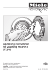
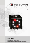
36
Sputtering of Niobium Thin Film onto a Copper Cavity
Table 4.1 suggests a possible temperature set.
Zone
Temperature (◦ C)
1
Cathode
150
2
Cavity
150
3
Gate
100
4
Gauges and CF35 flanges
150
5
Pre-chamber
150
Bypass
150
Turbomolecular Pump
120
7
Table 4.1: Standard baking temperature set for every zone.
Take care to avoid cold spots during baking, which could affect the final vacuum.
Moreover, in case of power failure during baking, the gate would close and the pressure
would rise in the hot system, opening the way to the formation of not well defined oxides
on the cavity surface. It seems that for copper cavities this oxidation doesn’t affect the
final results.
Under the baking box there is the multifunction box (figure 4.12): on the right side
there is a control unit for fans system and heating collars. This units allows to control
the cavity temperature during coating. The temperature is measured by a thermocouple;
when it exceeds the set temperature the heating collar are switched off and the fan are
switched on.
On the left side of the multifunction box there is splitter for the nitrogen line. One line
goes to the nitrogen gas gun and the other line pass through a pressure reducer and goes
to the venting valve.
Figure 4.12: Multifunction box: from the front panel the operator can set an additional baking
units and he can also regulate the nitrogen gas pressure. In the rear panel there are two sockets
for the heating collar or the cooling fan plugs. One thermocouple is connected to the heating unit.