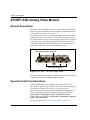
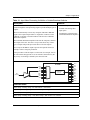
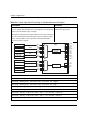
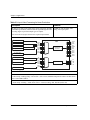
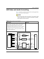
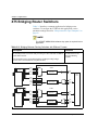
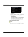
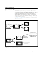
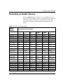
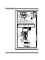
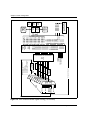
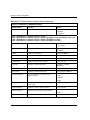
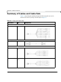
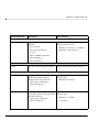
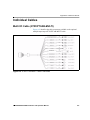
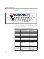
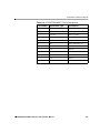
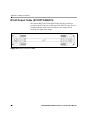
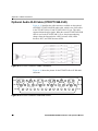
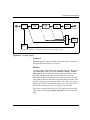
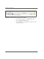
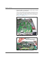
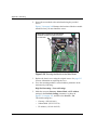
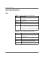
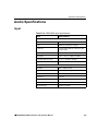
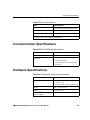
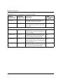
1
Multiple Path Converters
and Frame Synchronizers
Installation and Operation Manual
Edition J
175-000243-00
X85-3G/X85HD/X75SD
Multiple Path Converters
and Frame Synchronizers
Installation and Operation Manual
Edition J
December 2009
Trademarks and Copyrights
Copyright 2009 Harris Corporation, 1025 West NASA Boulevard,
Melbourne, Florida 32919-0001 U.S.A.
All rights reserved. This product and related documentation are
protected by copyright and are distributed under licenses restricting
their use, copying, distribution, and decompilation. No part of this
product or related documentation may be reproduced in any form by
any means without prior written authorization of Harris Corporation
and its licensors, if any. This publication could include technical
inaccuracies or typographical errors. Changes are periodically added to
the information herein; these changes will be incorporated into new
editions of the publication. Harris Corporation may make
improvements and/or changes in the product(s) and/or the program(s)
described in this publication at anytime.
All trademarks and tradenames are the property of their respective
owners.
Dolby is a registered trademark of Dolby Laboratories.
Warranty Information
The Limited Warranty Policy provides a complete description of your
warranty coverage, limitations, and exclusions, as well as procedures
for obtaining warranty service. To view the complete warranty, visit our
website.
This publication is provided “as is” without warranty of any kind, either
express or implied, including, but not limited to, the implied warranties
of merchantability, fitness for a particular purpose, or non-infringement.
ii
X85-3G/X85HD/X75SD Installation and Operation Manual
Contents
Preface
Manual Information ............................................................................. xiii
Purpose and Audience .................................................................. xiii
Revision History ........................................................................... xiii
Writing Conventions ............................................................................ xiv
Unpacking/Shipping Information ..........................................................xv
Safety Terms and Symbols .................................................................. xvi
Terms and Symbols Used in this Manual ..................................... xvi
Terms and Symbols Found on the Product ................................... xvi
Third-Party Software Licensing Agreement ....................................... xvii
Chapter 1: Introduction
Overview ..................................................................................................1
General Description .................................................................................2
Main Features ...........................................................................................5
X75 and X85 General Functionality .................................................5
Input/Outputs ....................................................................................6
Operation, Control, and Monitoring .................................................6
Hardware Features ............................................................................6
X85 Additional Features ...................................................................7
Front and Rear Panels ..............................................................................8
Product Packages .....................................................................................9
Front and Back Modules ........................................................................15
X75OPT-AS-32 /X75OPT-AS-16 /X75OPT-AS-8 Audio Modules .....16
General Description ........................................................................16
Required Jumper Settings and Local Configuration .......................18
Special Control Considerations ......................................................21
X75OPT-AS-32, X75OPT-AS-16, or X75OPT-AS-8-L
X85-3G/X85HD/X75SD Installation and Operation Manual
iii
Contents
Audio Limiters ............................................................................... 21
X75OPT-A3D Analog Video Module .................................................. 24
General Description ....................................................................... 24
Special Control Considerations ...................................................... 24
X75OPT-PQM Video Module .............................................................. 25
General Description ....................................................................... 25
Special Control Considerations ...................................................... 25
Alternate PQM Color Decoding Algorithm (NTSC Only) ............ 26
X75OPT-HDUPG HDTV Video Module ............................................. 27
General Description ....................................................................... 27
Special Control Considerations ...................................................... 28
X85OPT-HDUPG HDTV Video Module ............................................. 29
General Description ....................................................................... 29
Special Control Considerations ...................................................... 30
X75OPT-STR Streaming Video Module .............................................. 31
General Description ....................................................................... 31
Minimum Requirements ................................................................ 32
Typical Control Configurations ............................................................ 33
Signal Flow ........................................................................................... 35
Chapter 2: Operating Modes
Overview ............................................................................................... 41
Video Functional Block Diagram ......................................................... 42
Operating Modes ................................................................................... 43
X85 Signal Flow Diagrams for Operating Modes ......................... 44
X75 Video Operating Modes ......................................................... 46
Program Delay ............................................................................... 55
Chapter 3: Applications
Overview ............................................................................................... 57
X85 Input Video Processing ................................................................. 58
X85 Video and Audio Converting ........................................................ 63
X85 Bridging Router Switchers ............................................................ 65
X85 Simulcast Switching ...................................................................... 66
X75 Input Video Processing ................................................................. 67
X75 Video and Audio Converting ........................................................ 72
X75 Bridging Router Switchers ............................................................ 74
X75 Simulcast Switching ...................................................................... 75
iv
X85-3G/X85HD/X75SD Installation and Operation Manual
Contents
Chapter 4: Installation
Overview ................................................................................................77
Checking the Packing List .....................................................................78
Standard Items ................................................................... 78
Optional Items .................................................................... 78
Replaceable Parts Kit ........................................................ 78
Preparing for Installation .......................................................................79
Meeting Electrical Requirements ....................................................79
Meeting Environmental Requirements ...........................................79
Rack Mounting .......................................................................................81
Making Cable and System Connections ................................................84
Video Connections ..........................................................................84
Audio Connections .........................................................................88
Remote Control Ports ......................................................................89
Chapter 5: Operation via Front Panel Controls
Overview ................................................................................................91
Front Panel Description .........................................................................92
Using the Control Knob and Menu Control Buttons .............................93
Setting the Direction of the Control Knob ......................................93
Using Multi-Function Buttons ........................................................94
Navigating Through the Menus ......................................................94
Changing Parameters ......................................................................96
Buttons ...................................................................................................99
Freeze Button ..................................................................................99
Video In/Video Proc Amp/Video Configuration Buttons ............100
Audio In/Audio Proc Amp/Audio Configuration Buttons ............101
Memory Button .............................................................................105
FAV1 and FAV2 Button ...............................................................108
Bypass Button ...............................................................................111
Mono/Stereo Button ......................................................................111
Noise Reduction Button ................................................................111
Test Signal Generator Button .......................................................113
ARC (Aspect Ratio Converter) Button .........................................113
Timing Button ...............................................................................114
Option Button ...............................................................................114
Rebooting Shortcut ..............................................................................116
Display Screen Setup Parameters ........................................................117
X85-3G/X85HD/X75SD Installation and Operation Manual
v
Contents
Scroll Mode .................................................................................. 117
Display Intensity .......................................................................... 117
Screen Saver Timeout .................................................................. 117
Screen Saver Select ...................................................................... 118
Shaft Direction ............................................................................. 118
1 Click Favorite ............................................................................ 118
Force DPS Protocol ...................................................................... 118
Backlite ........................................................................................ 118
Status and Alarm LEDs ....................................................................... 119
Presets .................................................................................................. 122
Preset Quick Select ...................................................................... 122
SD ARC Quick Select .................................................................. 124
SDI ARC Quick Select ................................................................ 125
GPI In Presets ............................................................................... 125
Remote Access to Presets ............................................................ 126
Chapter 6: Operation by Web Server Software
Overview ............................................................................................. 129
Launching the Web Server Software .................................................. 130
Controlling Devices ............................................................................. 131
Navigating from the Main Menu Page ......................................... 131
Setting a Selected Value .............................................................. 134
Navigating Menus and Options via the Menu Navigation Tree .......... 137
Monitoring Alarms .............................................................................. 138
Thumbnail Streaming ................................................................... 138
Getting Help ........................................................................................ 141
Chapter 7: Initial Configuration
Overview ............................................................................................. 143
Initial Power-Up and Control Steps .................................................... 144
Configuring Network Settings ............................................................ 146
Supported Network Protocols ...................................................... 146
Making Required Hardware Connections .................................... 146
Setting IP and Subnet Mask Addresses ........................................ 147
Changing the PC Network Settings ..................................................... 150
Remotely Controlling X85/X75 Systems ............................................ 153
Preparing for Remote Control via Control Panel ......................... 153
Selecting a Remote Unit to Control ............................................. 154
Configuring for HTTP Control via Web Browser ....................... 156
vi
X85-3G/X85HD/X75SD Installation and Operation Manual
Contents
Configuring for CCS Software Control ........................................157
Configuring for SNMP and Third-Party Software Control ..........157
Processing Modes ................................................................................159
General Information ......................................................................159
Input Video Modes .......................................................................160
Configuration Exceptions and Further Information ......................162
Configuring the GPI .............................................................................164
Alarm Options ......................................................................................165
Chapter 8: Video Configuration
Overview ..............................................................................................167
Selecting a Video Source .....................................................................168
General Information ......................................................................168
Procedure ......................................................................................169
Forcing Video Standards ..............................................................171
Adjusting Video Levels .......................................................................172
Video/Audio Timing Tool ...................................................................172
Transmitter ....................................................................................173
Receiver ........................................................................................174
Typical Applications .....................................................................176
Logo Generator and Inserter ................................................................177
Basic Steps to Installing Logo Files .............................................178
Step 1: Install LogoCreator Software ...........................................179
Step 2: Convert Files to the .mg2 Format .....................................179
Step 3: Transfer the Logos to the SD Card ...................................185
Step 4: Set the Parameters and Load the Logo Files ....................187
Step 5: Make the GPI Settings (Optional) ....................................190
I-Wings Integrated Graphics Content Insertion ...................................191
SDI (HD) Processing Bypass Mode .....................................................194
Aspect Ratio Conversion .....................................................................196
Setting a Custom, Standard, or Automatic Aspect Ratio ..............196
Setting a Custom Aspect Ratio .....................................................197
Setting an Aspect Ratio Automatically .........................................197
Incoming AFD, VI and WSS Detection .......................................203
Output AFD, VI and WSS ............................................................203
Closed Captioning and DVB Teletext Captioning ...............................210
Input Detection .............................................................................210
Output Embedding ........................................................................211
Color Correction ..................................................................................211
X85-3G/X85HD/X75SD Installation and Operation Manual
vii
Contents
X75 Minimum Requirements ....................................................... 212
Gain .............................................................................................. 213
Offset ............................................................................................ 214
White Slope and Black Stretch .................................................... 214
Gamma Correction ....................................................................... 216
Frame Rate Converter (X85 Only) ...................................................... 219
Installation Notes ......................................................................... 220
Chapter 9: Audio Configuration
Overview ............................................................................................. 223
General Information ............................................................................ 224
Selecting an Audio Source .................................................................. 225
Adjusting Audio Levels ...................................................................... 227
Audio LED and Buttons Map .............................................................. 228
Selecting an Audio Input .............................................................. 228
Accessing Audio Level Controls ................................................. 229
Tracking and Delaying Audio ...................................................... 229
AFV (Audio Follow Video) ......................................................... 230
Advanced Audio Inputs and Outputs Selection ........................... 233
Audio Embedding and De-embedding ................................................ 233
Dolby E Embedding ............................................................................ 240
Audio Delays in Dolby E and AC-3 ............................................ 242
Backup Dolby Input for 32-Channel Modules ............................. 243
Audio Metadata ................................................................................... 244
DTS Neural Audio Delays ........................................................... 244
Dolby and DTS Neural Audio Licenses .............................................. 246
Block Diagrams ................................................................................... 247
Dolby ............................................................................................ 247
DTS Neural .................................................................................. 248
DTS Neural Audio Parameters ............................................................ 251
General Steps for Routing DTS Neural Audio ............................ 251
DTS Neural Audio UpMix ........................................................... 252
DTS Neural Audio DownMix ...................................................... 254
DTS Neural Audio MultiMerge ................................................... 256
DTS Neural Loudness Control ..................................................... 260
Appendix A: Cables and Pinouts
Overview ............................................................................................. 263
Summary of Cables and Cable Sets .................................................... 264
viii
X85-3G/X85HD/X75SD Installation and Operation Manual
Contents
Analog Audio Connections ..................................................................276
Individual Cables .................................................................................277
Multi I/O Cable (X75OPTCAB-MULTI) .....................................277
DVI-D Output Cable (X75OPTCAB-DVI) ..................................280
Audio Coax Cable (X75OPTCAB-8-C) .......................................281
Audio Coax Cable (CAB-X75HD-COAX) ..................................283
Audio BNC/XLR Cable (X75OPTCAB-8-XC) ...........................285
Audio BNC/XLR Cable (CAB-X75HD-COMBO) ......................287
Optional Audio XLR Cable (X75OPTCAB-8-X) ........................290
Optional Audio XLR Cable (X75OPTCAB-XLR) ......................292
Appendix B: Troubleshooting
Overview ..............................................................................................295
Network Connectivity ..........................................................................296
Forgotten IP address .....................................................................296
No response to SNMP Walk command ........................................298
Front Panel Display ..............................................................................299
Control panel display is blank ......................................................299
Analog input video control menu is not showing up ....................302
Power LEDs are off and there is no display on the LCP ..............303
Video Conversion ................................................................................304
Performing an HD cross-conversion but can’t see the down-converted
signal using an X75 .......................................................................304
Won’t perform up and down conversions simultaneously ...........306
Audio ....................................................................................................308
Lip sync problems .........................................................................308
Not passing the embedded audio ..................................................311
Analog input audio control menu not showing up ........................312
Alarms ..................................................................................................313
Major and Minor Alarms are on ...................................................313
Softkey Installation ..............................................................................315
Can’t activate softkeys ..................................................................315
Flash Memory ......................................................................................317
Flash memory is locked ................................................................317
Upgrading Firmware ............................................................................320
Software can’t upload ...................................................................320
RCP is not booting up properly after upgrade ..............................323
Software file updated incorrectly or became corrupted ................325
Problems with Pinging .........................................................................327
X85-3G/X85HD/X75SD Installation and Operation Manual
ix
Contents
Appendix C: Servicing
Overview ............................................................................................. 329
Safety Precautions ............................................................................... 330
Laser Caution ............................................................................... 330
ESD Caution ................................................................................ 330
Understanding and Working With Fiber Optics ................................. 331
Basic Principles ............................................................................ 331
Handling and Connecting Fibers .................................................. 332
Cleaning Optical Fibers ............................................................... 334
Preparing the X75 or X85 for Servicing ............................................. 335
Common Replacement Part Numbers ................................................. 336
Installing the Software Keys ............................................................... 336
Installing a Frame-Mounted Local Control Panel ............................... 337
Installing and Removing an Audio Synchronizer Module .................. 339
Installing a New Module .............................................................. 339
Removing an Existing Module .................................................... 343
Installing and Removing an X75OPT-HDUPG HDTV Module ........ 344
Installing a New Module .............................................................. 344
Removing an Existing X75 Module ............................................. 348
Installing and Removing an X85XOPT-HDUPG HDTV Module ...... 349
Installing a New Module .............................................................. 349
Optional SFP Receiver and Transmitter Modules ....................... 353
Removing an X85 Module ........................................................... 355
Program Delay Memory Module Installation .............................. 356
Installing and Removing X75OPT-A3D or X75OPT-PQM Video Modules
357
Installing a New Module .............................................................. 357
Removing an Existing Module .................................................... 361
Configuring an X75OPT-A3D-1 Module .................................... 361
Installing and Removing the Streaming Module ................................. 363
Installing a New Module .............................................................. 363
Removing an Existing Module .................................................... 366
Launching QuickTime in CCS Pilot and Navigator .................... 366
Installing Software Options ................................................................. 369
Installing a Software Option ........................................................ 369
Operating the X75OPT-AS-32 /16 /8-L Audio Limiters ............. 369
Installing Dolby and DTS Neural Advanced Audio Modules ............ 372
Software Installation .................................................................... 372
Hardware Installation ................................................................... 372
x
X85-3G/X85HD/X75SD Installation and Operation Manual
Contents
Data Port Information ..........................................................................378
Replacing a Power Supply ...................................................................380
Installing a Redundant Power Supply ..................................................383
Installing Fans ......................................................................................389
X75-RCP Fuse Rating and Replacement .............................................392
X85 HDTV Module Fuse Replacement ...............................................392
Appendix D: Software
Overview ..............................................................................................393
Software Upgrading Overview ............................................................394
Upgrading Procedure Using CCS Applications ...................................394
Upgrading Procedure Using an SD Card .............................................397
Configuring SNMP Support .................................................................398
Configuring Third-Party SNMP Software Control .......................402
Monitoring and Control Using MIBs ...................................................404
Appendix E: Specifications
Overview ..............................................................................................409
Video Specifications ............................................................................410
Input ..............................................................................................410
Output ...........................................................................................414
Audio Specifications ............................................................................419
Input ..............................................................................................419
Output ...........................................................................................420
I/O Specifications .................................................................................422
Communication Specifications ............................................................423
Hardware Specifications ......................................................................423
Power Consumption .............................................................................424
X75 HD Conversion Capabilities ........................................................429
X85 Conversion Capabilities ...............................................................430
X75 and X85 Video Propagation Delays .............................................430
X85/X75-RCP Specifications ..............................................................431
Dimensions and Weight ................................................................431
Network Control ...........................................................................431
Power Consumption ......................................................................431
Index
Keywords .............................................................................................433
X85-3G/X85HD/X75SD Installation and Operation Manual
xi
Contents
xii
X85-3G/X85HD/X75SD Installation and Operation Manual
Preface
Manual Information
Purpose and Audience
This manual details the features, installation procedures, operational
procedures, and specifications of the X85-3G/X85HD/X75SD Multiple
Path Converters and Frame Synchronizers. It is written for engineers,
technicians, and operators responsible for the installation, setup, and/or
operation of the product.
Revision History
Table P-1. Manual Revision History
Edition
Date
Details
Preliminary
December 2004
Preliminary release
A
January 2005
Initial release
B
April 2005
Addition of SD capabilities, new packages, options, and index
C
June 2005
Addition of X75OPT-HDDUOCON option, software upgrade procedures, and alarms list
D
March 2006
Addition of streaming and video/audio timing options, improved alarms list, specifications and
features changes
E
July 2006
Addition of 32-channel audio information
F
February 2007
Addition of Dolby® encoding hardware and software
G
August 2007
Addition of logo generator, I-wings, HD Processing Bypass mode, color correction, Active
Frame Description, audio metadata, and DVB Teletext Captioning
H
October 2008
Addition of new color correction and AC-3 Dolby encoding
I
February 2009
Addition of X85HD capability
J
December 2009
Addition of DTS Neural audio options
X85-3G/X85HD/X75SD Installation and Operation Manual
xiii
Preface
Writing Conventions
To enhance your understanding, the authors of this manual have
adhered to the following text conventions:
Table P-2. Writing Conventions
Term or
Convention
Bold
Indicates dialog boxes, property sheets, fields, buttons,
check boxes, list boxes, combo boxes, menus, submenus,
windows, lists, and selection names
Italics
Indicates email addresses, the names of books or
publications, and the first instances of new terms and
specialized words that need emphasis
CAPS
Indicates a specific key on the keyboard, such as ENTER,
TAB, CTRL, ALT, or DELETE
Code
Indicates variables or command-line entries, such as a
DOS entry or something you type into a field
>
Indicates the direction of navigation through a hierarchy
of menus and windows
hyperlink
Indicates a jump to another location within the electronic
document or elsewhere
Internet
address
Indicates a jump to a Web site or URL
Note
xiv
Description
Indicates important information that helps to avoid and
troubleshoot problems
X85-3G/X85HD/X75SD Installation and Operation Manual
Preface
Unpacking/Shipping Information
This product was carefully inspected, tested, and calibrated before
shipment to ensure years of stable and trouble-free service.
1. Check equipment for any visible damage that may have occurred
during transit.
2. Confirm that you have received all items listed on the packing list.
3. Contact your dealer if any item on the packing list is missing.
4. Contact the carrier if any item is damaged.
5. Remove all packaging material from the product and its associated
components before you install the unit.
Keep at least one set of original packaging, in the event that you need to
return a product for servicing.
Product Servicing
Except for the installation of modules and firmware upgrades, X75 and
X85 products are not designed for field service. For repairs and
modifications that are not described in this manual, contact Customer
Service at the number listed on the back cover.
Returning a Product
In the unlikely event that your product fails to operate properly, please
contact Customer Service to obtain a Return Authorization (RA)
number, then send the unit back for servicing.
Keep at least one set of original packaging in the event that a product
needs to be returned for service. If the original package is not available,
you can supply your own packaging as long as it meets the following
criteria:
•
The packaging must be able to withstand the product’s weight.
•
The product must be held rigid within the packaging.
•
There must be at least 2 in. (5 cm) of space between the product and
the container.
•
The corners of the product must be protected.
Ship products back to us for servicing prepaid and, if possible, in the
original packaging material. If the product is still within the warranty
period, we will return the product prepaid after servicing.
X85-3G/X85HD/X75SD Installation and Operation Manual
xv
Preface
Safety Terms and Symbols
Terms and Symbols Used in this Manual
WARNING statements and icons identify conditions or practices
that can result in personal injury or loss of life. High voltage is
present. Uninsulated dangerous voltage within the product’s
enclosure may be sufficient to constitute a risk of electric shock to
persons.
CAUTION statements and icons identify conditions or practices
that can result in damage to the equipment or other property.
Important operating and maintenance (servicing) instructions are
included in the literature accompanying the product.
CAUTION statements and icons identify conditions or practices
that can result in damage to the equipment or other property if
proper care during use and transport is not taken.
Terms and Symbols Found on the Product
DANGER: Indicates a hazard for high voltage, fire, or personal
injury immediately accessible as one reads the marking
WARNING: Indicates a personal injury hazard not immediately
accessible as one reads the marking
CAUTION: Indicates a hazard to property, including the product,
or the need to take attention and refer to the manual
Protective ground (earth) terminal
FUSE: Replace with same type and rating of fuse
Observe precautions for handling electrostatic-sensitive devices
xvi
X85-3G/X85HD/X75SD Installation and Operation Manual
Preface
Third-Party Software Licensing Agreement
If the software embedded in this product incorporates the VxWorks
Run-Time Module, the following paragraphs are applicable:
You are prohibited from:
a) copying the Run-Time Module, except for archive purposes
consistent with your archive procedures;
b) transferring the Run-Time Module to a third party apart from the
product containing the Run-Time Module;
c) modifying, decompiling, disassembling, reverse engineering or
otherwise attempting to derive the source code of the Run-Time
Module;
d) exporting the Run-Time Module of underlying technology in
contravention of applicable U.S. and foreign export laws and
regulations, and
e) using the Run-Time Module other than in connection with operation
of the product in which it is embedded.
Any further distribution of the Run-Time Module is subject to the same
restrictions set forth herein. Wind River Systems, Inc. and its licensors
are third party beneficiaries of the End User License Agreement and the
provisions related to the Run-Time Module are made expressly for the
benefit of, and are enforceable by, Wind River Systems, Inc. and its
licensors.
The laws of the Province of Ontario shall govern this Agreement.
Updated 2007.
X85-3G/X85HD/X75SD Installation and Operation Manual
xvii
Preface
xviii
X85-3G/X85HD/X75SD Installation and Operation Manual
Chapter 1
Introduction
Overview
The Harris X85-3G/X85HD/X75SD series includes standard and
high-definition utility synchronizers and converters that combine video
and audio processing with the ability to upconvert, downconvert, and
crossconvert from most common input and output video formats.
Models are available in 3G HD-SDI, 1.5G HD-SDI, SD-SDI, and
DPS-575-compatible versions—well-suited for hybrid facilities, and
the ideal choice for broadcasters making the transition to digital, 1.5G
high-definition, and 3G HDTV. Available in video-only and
audio/video configurations, the X85 and X75 provide a bridge between
analog, digital, and high-definition systems with analog, digital, and
embedded audio.
NOTE
This manual describes the operation of both X85 and X75 products.
Some functions of the X75HD module may differ from those
described in this manual when new firmware is added.
From a functional standpoint, the X85HD module incorporates more
inputs and outputs, and unlike the X75HD module, the X85HD
module processes both SD and HD signals. Because of this,
X85HD parameter names often include the term SDI to indicate
functions that operate through the X85HD module, where the
X75HD parameters would include the term HD. Parameter names
that include SD indicate functions that operate through the main
processing module of the frame. See the “Video Functional Block
Diagram” on page 42 for more information.
X85-3G/X85HD/X75SD Installation and Operation Manual
1
Chapter 1: Introduction
This chapter describes the main features and applications, under the
following topics:
•
“General Description” on page 2
•
“Main Features” on page 5
•
“Front and Rear Panels” on page 8
•
“Product Packages” on page 9
•
“Front and Back Modules” on page 15
•
“X75OPT-AS-32 /X75OPT-AS-16 /X75OPT-AS-8 Audio
Modules” on page 16
•
“X75OPT-A3D Analog Video Module” on page 24
•
“X75OPT-PQM Video Module” on page 25
•
“X75OPT-HDUPG HDTV Video Module” on page 27
•
“X85OPT-HDUPG HDTV Video Module” on page 29
•
“X75OPT-STR Streaming Video Module” on page 31
•
“Typical Control Configurations” on page 33
•
“Signal Flow” on page 35
General Description
Offering unparalleled flexibility, the X85-3G/X85HD/X75SD product
line provides up to nine video inputs and ten video output formats,
depending upon the following available options:
•
•
•
•
•
•
•
•
•
2
Two HDTV optical fiber serial component digital video inputs and
outputs (X85) or one HDTV optical fiber serial component digital
video input and output (X75)
Two HDTV coaxial inputs and outputs on independent paths (X85)
or two HDTV coaxial inputs and outputs using the same path (X75)
Two SD-SDI serial component digital video inputs and outputs
One 128 x 96 thumbnail streaming source and one 352 x 240 pixel
(525) or 352 x 288 pixel (625) streaming-over-IP video/audio
output
Component analog video (Betacam®) input and output
S-video (S-VHS/Hi8) input and output
NTSC/PAL-M/PAL-B/SECAM composite video input and output
RGB-S output
DVI-D output
X85-3G/X85HD/X75SD Installation and Operation Manual
Chapter 1: Introduction
See page 57 for descriptions of some typical applications using these
options, and “Product Packages” on page 9 for more specific
information on what each X85-3G/X85HD/X75SD system package
provides.
Inputs
Inputs are capable of auto-detection, with user-selectable SMART
alarms. Two input modes (both of which allow for either automatic
detection or user-selection of inputs) are available for processing
critical program paths for ingest, and bridging between routers/tape
transports/servers, mobile broadcast, and edit suites.
Video Processing
Processing for video includes level/color control, aspect ratio
conversion, 3D-adaptive color decoding, noise reduction, frame
synchronization and time base correction for non-synchronous signals,
analog-to-digital and digital-to-analog video conversion.
Other capabilities include the following:
•
Up and down conversion
•
Aspect ratio control
•
High-definition cross-conversion
Audio Processing
Processing for audio includes level control, analog-to-digital and
digital-to-analog conversion, and SD-SDI and HD-SDI serial digital
signal embedding and de-embedding.
Other capabilities include the following:
•
Sample rate conversions, synchronization, and timing-to-video for
correction of lip sync errors
•
Embedding/de-embedding of signals such as Dolby E™ and AC-3™
•
Processing of multiple channel program signals for surround-sound
applications before or after compression
•
Audio-follow-video routing
•
Converting, adjusting, timing, demultiplexing, and multiplexing
X85-3G/X85HD/X75SD Installation and Operation Manual
3
Chapter 1: Introduction
Signal Control and Monitoring
You can control and monitor signals using a variety of methods:
•
•
•
•
•
•
•
•
Local X85-3G/X85HD/X75SD control panels
Remote X75-RCP control panels
Web server software
Local DPS-575 control panels
Remote RC-575 control panels
CCS™-enabled hardware controls
CCS software applications and QuickTime Player
SNMP control systems
Operating Modes
The X85 and X75 have four main operational modes:
•
Auto Detect (default mode)
•
M-Path (multiple path)
•
Simulcast
•
All Output Select
In addition, the X85 also provides a Program Delay mode.
See page 43 for more information on modes of operation.
4
X85-3G/X85HD/X75SD Installation and Operation Manual
Chapter 1: Introduction
Main Features
The following standard and optional features are described in this
document:
X75 and X85 General Functionality
•
Upgradability from SDTV to HDTV, and HDTV to 3 Gb/s
•
Frame syncs for analog, SDTV and HDTV
•
Upconversion, downconversion, crossconversion, and aspect ratio
conversion
•
Analog-to-digital conversion
•
Digital-to-analog conversion
•
Proc amps for analog, SDTV and HDTV
•
Video test generation
•
Optional video noise reduction and enhancement
•
Optional HD and SD color correction
•
8, 16, or 32 channels of internal audio processing (gain, invert,
swap, sync/delay, sum)
•
Embedding and de-embedding for SD-SDI, HD-SDI, and 3 Gb/s
•
Compressed audio capability (Dolby E® and AC-3®)
•
Video and audio timing correction
•
Streaming video capability
•
SD memory card parameter settings storage
•
Audio (and embedded) test generation
•
Audio limiting capability
•
Built-in Web server with thumbnail monitoring capability
•
Available redundant power supply
•
Active Format Description (AFD), audio metadata, closed
captioning, and DVB Teletext captioning capabilities
•
Optional program delay for video and embedded audio
X85-3G/X85HD/X75SD Installation and Operation Manual
5
Chapter 1: Introduction
Input/Outputs
•
Auto-detected inputs
•
Two SD-SDI and two HD-SDI inputs
•
Color black, tri-level sync and DARS reference inputs
•
Optional NTSC/PAL-M/PAL-B/SECAM input with CAV and
S-video inputs
•
Ability to provide many outputs, including composite, component,
SD-SDI, HD-SDI, HDTV fiber, DVI-D, and S-video
•
SC and optional FC/ST fiber interface for HD-SDI
(X75OPT-HDUPG HDTV module) or LC/SFP connectors for
SD/HD-SDI (X85OPT-HDUPG HDTV module)
•
Two, five, or eight AES inputs and outputs, at 75Ω or 110Ω
•
Four analog audio inputs and outputs
•
GPI inputs and outputs
Operation, Control, and Monitoring
•
Four operating modes in the X85 products, three in the X75
products
•
Local and remote control panels
•
Control for up to 200+ units from a single control panel
•
X75 Web server software application
•
Software GUI control and monitoring using CCS Navigator
•
SNMP and third-party interfaces
•
SMART alarms (global parameters for all inputs—allowing
custom-definitions for how and when alarms are activated,
including priority settings for main and backup inputs)
Hardware Features
6
•
SD (Secure Digital) removable media for storage of parameter
settings; 128 MB included (the maximum size supported by the
X85/X75 is 2 GB)
•
Front-to-back air flow
•
Single and dual redundant power supplies
X85-3G/X85HD/X75SD Installation and Operation Manual
Chapter 1: Introduction
X85 Additional Features
•
3 Gb/s capability
•
Profanity avoidance option (Program Delay)
•
V2A functionality for 3Gb/s
NOTE
A free trial version of CCS Navigator is packaged with each new
X85-3G/X85HD/X75SD order. After the trial period, the program
retains only Discovery and code update capabilities if the full
program is not purchased. Most features described in this manual
continue to operate using early versions of CCS Pilot and Navigator
software.
X85-3G/X85HD/X75SD Installation and Operation Manual
7
Chapter 1: Introduction
Front and Rear Panels
X85 and X75 have slightly different front and back panel appearances.
Descriptions of the individual processing modules, begin on page 15.
For typical control configurations, see page 33.
X85-3G/X85HD/X75SD units with a blank front panel, must be
configured and controlled remotely, using one of the following
methods:
•
Separate control panel such as an X75-RCP
•
Local control panel on an X85-3G/X85HD/X75SD or DPS-575
•
CCS applications such as Pilot or Navigator
•
Web server application using a common Web browser such as
Internet Explorer™ or Netscape™
•
SNMP (Simple Network Management Protocol) and third-party
control software offered through CCS Protocol
Blank front panels provide LEDs for alarm and status monitoring,
(including major and minor alarm LEDs), and status LEDs for power
and memory access.
NOTE
DPS-575 units do not have the Ctrl button found on X85-3G/
X85HD/X75SD models. Button shortcuts on
X85-3G/X85HD/X75SD models that require the Ctrl button are not
accessible remotely via a DPS-575 unit. In these cases, the
affected parameters must be accessed through the menu structure.
Local and remote control panels contain LEDs that indicate alarm,
status, and configuration information.
8
X85-3G/X85HD/X75SD Installation and Operation Manual
Chapter 1: Introduction
Product Packages
X75HD/X75SD models are available in a wide range of product
packages, and with a large number of options for modules, connectors,
cables, and software. All of the frames described in the next pages are
capable of single-channel up, down, and cross conversion.
Table 1-1 describes the various X85 and X75 product packages and
options that you can order. Some options are installed in the factory at
the time of purchase, while other options and upgrades can be ordered
and installed at a later time. The X75OPT-HDDUOCON software key
option is required for simultaneous up, down, and cross conversion.
For further information about the cables described in this table, see
“Cables and Pinouts” in Chapter A, page 263
Table 1-1. X85 and X75 Options and Packages
Item Number
Description
DPS-575 Equivalent Models with Extras
X75-DPS-575
X75SD Equivalent to DPS-575: 1RU Digital Synchronizer, Video Only, Local
Control Panel, includes X75OPT-A3D Analog Video input
X75-DPS-575LC
X75SD Equivalent to DPS-575LC, 1RU Digital Synchronizer, video only, no
control panel, includes X75OPT-A3D analog video input
X75-DPS-575AV
X75SD Equivalent to DPS-575AV, 1RU Digital Synchronizer, video and
8-channel audio, local control panel, includes X75OPT-A3D analog video input
X75-DPS-575LCAV
X75SD Equivalent to DPS-575LCAV, 1RU Digital Synchronizer, video and
8-channel audio, no control panel, includes X75OPT-A3D analog video input
X75SD Digital Standard Definition
X75SD
1RU Digital Synchronizer, Video Only, Local Control Panel
X75SD-LC
1RU Digital Synchronizer, Video Only, No Control Panel
X75SD-AV
1RU Digital Synchronizer, Video and 8 Channel Audio, Local Control Panel
X75SD-LCAV
1RU Digital Synchronizer, Video and 8 Channel Audio, No Control Panel
X75SD Digital Standard Definition and Redundant Power Supply
X75SD-2PS
1RU Digital Synchronizer, Video Only, Local Control Panel, Redundant Power
Supply
X75SD-LC-2PS
1RU Digital Synchronizer, Video Only, No Control Panel, Redundant Power
Supply
X85-3G/X85HD/X75SD Installation and Operation Manual
9
Chapter 1: Introduction
Table 1-1. X85 and X75 Options and Packages (Continued)
Item Number
Description
X75SD-AV-2PS
1RU Digital Synchronizer, Video and 8 Channel Audio, Local Control Panel,
Redundant Power Supply
X75SD-LCAV-2PS
1RU Digital Synchronizer, video and 8-channel audio, no control panel, redundant
power supply
X85 with Dual Up, Down, Cross Conversion
X85HD
1RU Up/Down/Cross Converter & Synchronizer, Video Only, Local Control Panel
(Dual Channel .27/1.5 Gb/s Conversion), for 3.0 Gb/s capability, the X85OPT-3G
software key option is required
X85HD-LC
1RU Up/Down/Cross Converter & Synchronizer, Video Only, No Control Panel
(Dual Channel .27/1.5 Gb/s Conversion), for 3.0 Gb/s capability, the X85OPT-3G
software key option is required
X85HD-AV
1RU Up/Down/Cross Converter & Synchronizer, Video and 16 Channel Audio,
Local Control Panel (Dual Channel .27/1.5 Gb/s Conversion), for 3.0 Gb/s
capability, the X85OPT-3G software key option is required
X85HD-LCAV
1RU Up/Down/Cross Converter & Synchronizer, Video and 16 Channel Audio, No
Control Panel (Dual Channel .27/1.5 Gb/s Conversion), for 3.0 Gb/s capability, the
X85OPT-3G software key option is required
X85 with Dual Up, Down, Cross Conversion, Redundant PSU
X85HD-2PS
1RU Up/Down/Cross Converter & Synchronizer, Video Only, Local Control
Panel, Redundant Power Supply (Dual Channel .27/1.5 Gb/s Conversion), for 3.0
Gb/s capability, the X85OPT-3G software key option is required
X85HD-LC-2PS
1RU Up/Down/Cross Converter & Synchronizer, Video Only, No Control Panel,
Redundant Power Supply (Dual Channel .27/1.5 Gb/s Conversion), for 3.0 Gb/s
capability, the X85OPT-3G software key option is required
X85HD-AV-2PS
1RU Up/Down/Cross Converter & Synchronizer, Video and 16 Channel Audio,
Local Control Panel, Redundant Power Supply (Dual Channel .27/1.5 Gb/s
Conversion), for 3.0 Gb/s capability, the X85OPT-3G software key option is
required
X85HD-LCAV-2PS
1RU Up/Down/Cross Converter & Synchronizer, Video and 16 Channel Audio, No
Control Panel, Redundant Power Supply (Dual Channel .27/1.5 Gb/s Conversion),
for 3.0 Gb/s capability, the X85OPT-3G software key option is required
10
X85-3G/X85HD/X75SD Installation and Operation Manual
Chapter 1: Introduction
Table 1-1. X85 and X75 Options and Packages (Continued)
Item Number
Description
X85-3G with Dual Channel Up, Down, Cross Conversion
X85-3G
1RU Up/Down/Cross Converter & Synchronizer, Video Only, Local Control Panel
(Dual Channel .27/1.5/3.0 Gb/s Conversion), X85OPT-3G option is included
X85-3G-LC
1RU Up/Down/Cross Converter & Synchronizer, Video Only, No Control Panel
(Dual Channel .27/1.5/3.0 Gb/s Conversion), X85OPT-3G option is included
X85-3G-AV
1RU Up/Down/Cross Converter & Synchronizer, Video and 32 Channel Audio,
Local Control Panel (Dual Channel .27/1.5/3.0 Gb/s Conversion), X85OPT-3G
option is included
X85-3G-LCAV
1RU Up/Down/Cross Converter & Synchronizer, Video and 32 Channel Audio, No
Control Panel (Dual Channel .27/1.5/3.0 Gb/s Conversion), X85OPT-3G option is
included
X85-3G with Dual Channel UP, Down, Cross Conversion, Redundant PSU
X85-3G-2PS
1RU Up/Down/Cross Converter & Synchronizer, Video Only, Local Control
Panel, Redundant Power Supply (Dual Channel .27/1.5/3.0 Gb/s Conversion),
X85OPT-3G option is included
X85-3G-LC-2PS
1RU Up/Down/Cross Converter & Synchronizer, Video Only, No Control Panel,
Redundant Power Supply (Dual Channel .27/1.5/3.0 Gb/s Conversion),
X85OPT-3G option is included
X85-3G-AV-2PS
1RU Up/Down/Cross Converter & Synchronizer, Video and 32 Channel Audio,
Local Control Panel, Redundant Power Supply (Dual Channel .27/1.5/3.0 Gb/s
Conversion), X85OPT-3G option is included
X85-3G-LCAV-2PS
1RU Up/Down/Cross Converter & Synchronizer, Video and 32 Channel Audio, No
Control Panel, Redundant Power Supply (Dual Channel .27/1.5/3.0 Gb/s
Conversion), X85OPT-3G option is included
X85 Hardware Options (may not be used in X75)
X85OPTPD-2
Program Delay Software Key License (up to approximately 27 seconds for .27
Gb/s, 10 seconds for 1.5 Gb/s, 5 seconds for 3.0 Gb/s), requires X85OPT-M2
Memory Module
X85OPTPD-2-M2
Program Delay Software Key License (up to approximately 27 seconds for .27
Gb/s, 10 seconds for 1.5 Gb/s, 5 seconds for 3.0 Gb/s), includes X85OPT-M2
Memory Module
X85OPTSC-SD
SD-to-SD Standards Conversion Software Key License; requires the
X85OPTPD-2-M2 program delay feature
X85OPTSC-HD
HD/SD-to-HD/SD Standards Conversion Software Key License; requires the
X85OPTPD-2-M2 program delay feature
X85-3G/X85HD/X75SD Installation and Operation Manual
11
Chapter 1: Introduction
Table 1-1. X85 and X75 Options and Packages (Continued)
Item Number
Description
X85OPTSC-SD-M2
SD-to-SD Standards Conversion Software Key License; includes X85OPT-M2
Memory Module
X85OPTSC-HD-M2
HD/SD-to-HD/SD Standards Conversion Software Key License; includes
X85OPT-M2 Memory Module
X85 Optical Fiber Options (may not be used in X75)
SFP+RR
Field Retrofit Fiber Receiver, dual inputs, standard sensitivity
SFP+TT+13+13L
Field Retrofit Fiber Transmitter, dual outputs, 1310nm FP lasers
X85 Software Key (may not be used in X75)
X85OPT-3G
3.0 Gb/s Input and Output option
X85OPT-CC
Color Correction Software Key Option for X85 - one SD and two SD/HD/3G color
correctors, (for 3G, the X85-3G model or X85HD model with the X85OPT-3G
software key is required)
X75 Hardware Options (may be used in X85)
X85OPT-HDUPG
HDTV submodule with Dual Auto Detected 270/1.5/3.0 Inputs and Dual 1.5/3.0
Output and Dual Up, Down or Cross Conversion, Coax and Optional Optical Input
and Output, for 3.0 Gb/s operation, the X75OPT-3G software key license is
required
X75OPT-A3D
Analog Video Input with high performance 3D fully-adaptive comb filtering,
S-Video and analog component Betacam inputs
X75OPT-A3D-1
Analog Video Input with Industry-Leading 3D fully-adaptive comb filtering,
S-Video and analog component Betacam inputs (with alternate color decoder
algorithm)
X75OPT-AS-32
32 Ch. Audio Synchronizer with 8 AES / SD & HD 4 Group Embedded Inputs and
Outputs, Includes Cable Set
X75OPT-AS-32-L
32 Ch. Audio Synchronizer with 8 AES / SD & HD 4 Group Embedded Inputs and
Outputs with Audio Limiting, Includes Cable Set
X75OPT-AS-16
16 Ch. Audio Synchronizer with 4 Ch. Analog / 5 AES / SD & HD 4 Group
Embedded Inputs and Outputs, Includes Cable Set
X75OPT-AS-16-L
16 Ch. Audio Synchronizer with 4 Ch. Analog / 5 AES / SD & HD 4 Group
Embedded Inputs and Outputs with Audio Limiting, Includes Cable Set
X75OPT-AS-8
8 Ch. Audio Synchronizer with 4 Ch. Analog / 2 AES / SD & HD 2 Group
Embedded Inputs and Outputs
12
X85-3G/X85HD/X75SD Installation and Operation Manual
Chapter 1: Introduction
Table 1-1. X85 and X75 Options and Packages (Continued)
Item Number
Description
X75OPT-AS-8-L
8 Ch. Audio Synchronizer with 4 Ch. Analog / 2 AES / SD & HD 2 Group
Embedded Inputs and Outputs with Audio Limiting
X75OPT-DOLBY-1
Dolby E and Digital (AC-3) Integrated decompression
X75OPT-DOLBY-2
Dolby E Integrated compression (call for details, fits new X75 units only)
X75OPT-DOLBY-3
Dolby Digital (AC-3) Integrated compression (call for details, fits new X75 units
only)
X75OPT-DM
DTS Neural Surround™ DownMix DTV 5.1 transport solution
X75OPT-DM-LC
DTS Neural Surround™ DownMix DTV 5.1 transport solution with DTS Neural Loudness
Control
X75OPT-LC
DTS Neural Loudness Control for 2.0 or 5.1 program audio
X75OPT-LC-6+2
DTS Loudness Control for 2.0 and 5.1 (separate programs)
X75OPT-LC-8
DTS Loudness Control for 4 x 2.0 program audio
X75OPT-LC+DM
DTS Loudness Control for 5.1 program audio with DTS Neural Surround™ Downmix
output
X75OPT-MM
DTS Neural Surround™ 5.1 and rendered stereo content transitioning for DTV 5.1
production
X75OPT-MM-LC
DTS Neural Surround™ 5.1 and rendered stereo content transitioning for DTV 5.1
production with DTS Neural Loudness Control
X75OPT-UM
DTS Neural Surround™ UpMix DTV 5.1 production solution
X75OPT-UM-LC
DTS Neural Surround™ UpMix DTV 5.1 production solution with DTS Neural Loudness
Control
X85-RCP
Remote Control Panel for X75, X85 and DPS-575
X75OPT-PS
Power Supply Field Retrofit Kit
X75OPT-STR
MPEG4 Monitor Streaming option (field retrofit for units with serial numbers
higher than LHTI0240085001)
X75OPT-LCP
Field Retrofit Kit (change a blank panel to a Local Control Panel) for X75
X85OPT-LCP
Field Retrofit Kit (change a blank panel to a Local Control Panel) for X85
X75 Hardware Options (may not be used in X85)
X75OPTFIBER-FC
FC type fiber connectors for HD submodule
X75OPTFIBER-ST
ST type fiber connectors for HD submodule
X85-3G/X85HD/X75SD Installation and Operation Manual
13
Chapter 1: Introduction
Table 1-1. X85 and X75 Options and Packages (Continued)
Item Number
Description
X75 Software Options (may be used in X85)
X75OPT-NR
Motion Adaptive Noise Reduction and Bandwidth Filtering for SDTV input signals
X75OPT-ASL
Audio Limiting Software Keyable Option
X75OPT-SNMP
SNMP Agent Software Keyable Option
X75OPT-V2A
Video/Audio Timing Tool Software Keyable Option for Receiving Units, any
updated X75 generates the test signal
X75 Software Options (may not be used in X85)
X75OPT-HDDUOCON
Optional Software Key, adds simultaneous Up and Down, or adds simultaneous
Cross and Down conversions to X75HD models
X75OPT-SD-CC
Color Correction Software Key Option for X75 (one SD color corrector)
X75OPT-HD-CC
Color Correction Software Key Option for X75 (one HD color corrector)
Optional Cables (for X75 and X85)
X75OPTCAB-8-C
Cable Set for 8 Ch. Audio Synchronizer, Unbalanced Coax AES (one set included)
X75OPTCAB-8-CX
Cable Set for 8 Ch. Audio Synchronizer, Unbalanced Coax AES and Balanced
XLR AES
X75OPTCAB-8-X
Cable Set for 8 Ch. Audio Synchronizer, Balanced XLR AES
X75OPTCAB-16-C
Cable Set for 16 Ch. Audio Synchronizer, Unbalanced Coax AES (one set
included)
X75OPTCAB-16-CX
Cable Set for 16 Ch. Audio Synchronizer, Unbalanced Coax AES and Balanced
XLR AES
X75OPTCAB-16-X
Cable Set for 16 Ch. Audio Synchronizer, Balanced XLR AES
X75OPTCAB-32-C
Cable Set for 32 Ch. Audio Synchronizer, Unbalanced Coax AES (one set
included)
X75OPTCAB-32-CX
Cable Set for 32 Ch. Audio Synchronizer, Unbalanced Coax AES and Balanced
XLR AES
X75OPTCAB-32-X
Cable Set for 32 Ch. Audio Synchronizer, Balanced XLR AES
X75OPTCAB-DVI
Cable for DVI-D Single Link Output
X75OPTCAB-MULTI
Cable Set for Multi IO Connector
14
X85-3G/X85HD/X75SD Installation and Operation Manual
Chapter 1: Introduction
Front and Back Modules
The X85/X75 is available with a wide variety of module combinations.
The following topics are included in this section:
•
“X75OPT-AS-32 /X75OPT-AS-16 /X75OPT-AS-8 Audio
Modules” on page 16
•
“X75OPT-A3D Analog Video Module” on page 24
•
“X75OPT-PQM Video Module” on page 25
•
“X75OPT-HDUPG HDTV Video Module” on page 27
•
“X85OPT-HDUPG HDTV Video Module” on page 29
•
“X75OPT-STR Streaming Video Module” on page 31
X85-3G/X85HD/X75SD Installation and Operation Manual
15
Chapter 1: Introduction
X75OPT-AS-32 /X75OPT-AS-16 /X75OPT-AS-8
Audio Modules
General Description
The X75OPT-AS-16/8 audio modules and associated back panels
provide 5 or 2 AES inputs and outputs, respectively, one DARS input, a
four-channel analog audio input, and a four-channel analog audio
output.
The X75OPT-AS-32 provides 8 AES inputs and outputs, in SD-SDI and
HD-SDI.
Using these modules, the X75HD/X75SD can process, embed, and
de-embed either 32, 16, or 8 channels of audio from/to SDTV and
from/to HDTV. The back panels for these modules are located in the
top, left corner of the frame, above the SDTV video connectors.
Analog audio
input connector
Analog audio
output connector DARS input
AES I/O connectors
Figure 1-1. X75OPT-AS-16/X75OPT-AS-8 Back Panel
AES 6 aAES 7 aAES8
AES 3 aAES 4 aAES5
AES 1 aAES 2 aDARS
Input/Output Connectors
Figure 1-2. X75OPT-AS-32 Back Panel
16
X85-3G/X85HD/X75SD Installation and Operation Manual
Chapter 1: Introduction
This module provides all audio processing for the X85/X75 and is
required to access, configure, and enable audio parameters in the Audio
Setup submenu (accessed from the main menu). Adjustable options
include gain, delay, tone, mute, voice-over, and AFV (audio follow
video).
X85-3G/X85HD/X75SD Installation and Operation Manual
17
Chapter 1: Introduction
Required Jumper Settings and Local Configuration
Setting Jumpers
To configure the impedances of analog audio inputs and outputs on the
X75OPT-AS-16 and X75OPT-AS-8 modules, you must set specific
jumpers. The X75OPT-AS-32 does not require jumper settings.
Jumpers 1 through 12 are located at the rear of the X75OPT-AS-16 and
X75OPT-AS-8 modules. Figure 1-3 on page 19 shows the location of
the jumpers. See Table 1-2 for the correct placement of the jumpers.
The white triangle next to each jumper indicates pin 1.
Table 1-2. Analog Audio Input and Output Impedance Jumper Settings (X75OPT-AS-16 and
X75OPT-AS-8 modules)
Input Settings
Input Number
Jumper Numbers
Channel
Pin Numbers
Setting
1
J5
Left (1A)
1 and 2
600Ω
2 and 3
100kΩ
1 and 2
600Ω
2 and 3
100kΩ
1 and 2
600Ω
2 and 3
100kΩ
1 and 2
600Ω
2 and 3
100kΩ
2
3
4
J6
J7
J8
Right (1B)
Left (2A)
Right (2B)
Output Settings
Output Number
Jumper Numbers
Channel
Pin Numbers
Setting
1
J1 and J9
Left (1A)
1 and 2
600Ω
2 and 3
66Ω
1 and 2
600Ω
2 and 3
66Ω
1 and 2
600Ω
2 and 3
66Ω
1 and 2
600Ω
2 and 3
66Ω
2
3
4
18
J2 and J10
J3 and J11
J4 and J12
Right (1B)
Left (2A)
Right (2B)
X85-3G/X85HD/X75SD Installation and Operation Manual
Chapter 1: Introduction
Jumpers for
inputs 4, 3, 2, 1
Jumpers for
outputs 4, 3, 2, 1
J4/12 J3/11 J2/10 J1/9
J8
J7
J6
J5
4 3 214 3 21
Figure 1-3. Jumper Locations for X75OPT-AS-16 and X75OPT-AS-8 Modules
X85-3G/X85HD/X75SD Installation and Operation Manual
19
Chapter 1: Introduction
Installing Audio Receptacles
To make analog audio input and output connections, you need to
properly connect stripped wires for each audio channel to the provided
audio receptacle. Once done, install the wired receptacle to the back
panel audio input and output connectors. Follow these steps:
1. Insert a small, flathead screw driver into a rectangular hole of the
audio receptacle.
The corresponding round wire hole will open either directly above
or directly below the screwdriver (see Figure 1-4).
2. Heeding the positive (+), negative (-), and ground (GND) markings
on the back panel, place an appropriate stripped audio wire into the
open hole.
The top row of wire connection holes alternate between positive
and ground. The bottom row of wire connection holes alternate
between negative and ground. See Figure 1-4.
Rectangular slot
Insert a flathead screwdriver into a rectangular slot to
open a corresponding round connection point (above or
below)
+ GND + GND + GND +
-
Connector
screw
+
G
+
G
+
G
+
-
G
-
G
-
G
-
CH1
CH2
CH3
CH4
Connector
screw
Figure 1-4. Installing Analog Audio Receptacles
3. Remove the screwdriver to lock the wire into place.
4. Repeat for other wire connections.
5. Once all wiring in completed, plug the receptacle into the analog
audio input ports (each labelled CH1 CH2 CH3 CH4), and then
secure the receptacle into place with the attached connector screws.
20
X85-3G/X85HD/X75SD Installation and Operation Manual
Chapter 1: Introduction
Special Control Considerations
For the AES input signals on DB-26 and DB-44 connectors, you can
select either an Unbalanced or Balanced input (Audio Setup > Input
Setup > AES & DARS Audio > AESx Bal/UnBal Sel). For coaxial
connections, select the default setting Unbalanced. For XLR
connections, select the Balanced setting.
X75OPT-AS-32, X75OPT-AS-16, or X75OPT-AS-8-L
Audio Limiters
Audio limiters are available as software options on all of the
X75OPT-AS audio synchronizers. The audio limiters have the
following available options:
•
•
•
•
•
•
•
•
Soft Limit Level
Slope
Attack Rate
Attack Time
Decay Rate
Decay Time
Noise Gate Level
Noise Gate Time
Figure 1-5 shows the transfer function of the audio limiter. Table 1-3 on
page 23 describes the various options of the audio limiter.
X85-3G/X85HD/X75SD Installation and Operation Manual
21
Chapter 1: Introduction
Output (dB)
Slope = 1.0
Slope = 0.75
Slope = 0.5
Slope = 0.25
Slope = 0.0
Threshold
Input (dB)
Figure 1-5. Audio Limiter Transfer Function
22
X85-3G/X85HD/X75SD Installation and Operation Manual
Chapter 1: Introduction
Table 1-3. Audio Limiter Options
Option
Description
Soft Limit Level
• Sets the threshold level for the input audio signal, measured in dB (decibels),
where the audio signal limiter's attack and decaying function will be based
• When a signal exceeds this level, compression will be applied
Slope
• Sets the amount a signal is reduced by the compressor
• When the slope is set to 0.25, the audio input signal exceeding the soft limit
threshold level will be reduced by the factor of 4 at the output.
Attack Rate
Controls the rate of attack soft limiting
Attack Time
• Activates limiter only after the input audio level remains over the Soft Limit
Level for the duration specified in the Attack Time option
• Audio that exceeds the specified Soft Limit Level for less than the specified
Attack time will not activate the limiter
• Attack Time indicates how long it takes for the compressor to act after a signal
has exceeded the threshold level
Decay Rate
Controls the rate of decay soft limiting.
Decay Time
• Once the input audio signal has exceeded the Soft Limit Level and the limiter
has been activated, the limiter remains active until the audio signal has returned
below the Soft Limit Level for the duration specified in the Decay Time option
• If the input audio signal returns below the Soft Limit Level for less than the
specified Decay Time, the limiter remains active
Noise Gate Level
• Sets the noise gate threshold level, measured in dB.
• When an input signal falls below this level, the noise gate will be applied.
Noise Gate Time
Indicates how long it takes for the noise gate to start or stop acting after the input
signal has fallen below or risen above the threshold level.
X85-3G/X85HD/X75SD Installation and Operation Manual
23
Chapter 1: Introduction
X75OPT-A3D Analog Video Module
General Description
The optional X75OPT-A3D analog video input module and associated
back panel provide selectable analog composite, component Betacam
(CAV), and S-video inputs (see Figure 1-6).
The composite input is processed through a high-performance industryleading 3D adaptive comb filter. The TBC mode is always used when
the S-video input is selected. When component analog video is selected
as the input, it is converted to digital and then further processed as
required. Looking from the rear, this back panel is located in the top,
right corner of the frame, above the dual Ethernet ports.
Analog composite
S-video input
video input connector connector
Y In
B-Y In
R-Y In
Component Betacam
video input connectors
Figure 1-6. X75OPT-A3D Module Back Panel
To access, configure, and enable the analog video parameters associated
with this module, enter the Video Setup parameter.
Special Control Considerations
Unlike SD-SDI inputs, only a single analog video source can be
auto-detected. Therefore, you must pre-select the desired analog input
video source (composite, S-video, or CAV) in order for the
auto-detection to work across the HD-SDI/SD-SDI/analog inputs. To
select a desired input, follow this path through the menu structure:
Video Setup > Analog Input (A3D) > Analog Video Source.
Additionally, set the module to Auto Detect (Video Setup > Routing
Setup > I/P Video Mode).
For more information, see “Input Video Modes” on page 160.
24
X85-3G/X85HD/X75SD Installation and Operation Manual
Chapter 1: Introduction
X75OPT-PQM Video Module
General Description
The optional X75OPT-PQM module and associated back panel provide
selectable analog composite, component Betacam (CAV), and S-video
inputs (see Figure 1-7). This module is an economical alternative to the
X75OPT-A3D option.
Composite input is processed through a 3D-adaptive comb filter. The
TBC mode is always used when the S-video input is selected. When the
component analog video input is selected, it is converted to digital and
then further processed as required. Looking from the rear, this back
panel is located in the top, right corner of the frame, above the dual
Ethernet ports.
Analog composite
S-video input
video input connector connector
B-Y In
Y In
R-Y In
Component Betacam
video input connectors
Figure 1-7. PQM-X75 Back Panel
To access, configure, and enable the analog video parameters associated
with this module, enter the Video Setup parameter.
Special Control Considerations
Unlike SD-SDI inputs, only a single analog video source can be
auto-detected. Therefore, you must pre-select the desired analog input
video source (composite, S-video, or CAV) in order for the
auto-detection to work across the HD-SDI/SD-SDI/analog inputs. To
select a desired input, follow this path through the menu structure:
Video Setup > Analog Input (PQM) > Analog Video Source.
Additionally, set the module to Auto Detect (Video Setup > Routing
Setup > I/P Video Mode).
For more information see “Input Video Modes” on page 160.
X85-3G/X85HD/X75SD Installation and Operation Manual
25
Chapter 1: Introduction
Alternate PQM Color Decoding Algorithm (NTSC Only)
The current version of the PQM decoder code provides a superior
separation of luma and chroma for the digital domain (SDI output). In
some cases, however, when the luma and chroma are re-combined in
the encoder, the resulting image may appear “soft” (see Figure 1-8).
X75 with X75OPT-PQM
NTSC
PQM color
decoder
color
encoder
SDI (PQM decoder separates luma and chroma for a
superior quality in the digital domain)
NTSC (quality is diminished due to back-to-back PQM decoder
and encoder depending on output timing or picture position)
Current PQM algorithm
Figure 1-8. Current PQM Algorithm
When this condition occurs, the X75HD/X75SD has a useful alternate
NTSC decoding algorithm that may provide better results. If an NTSC
output is required (via back-to-back decoder/encoder), you can enable
or disable the alternate PQM algorithm by following this path:
Video Setup > Analog Input (PQM) > Proc > Chroma Bandpass.
NOTE
The alternate PQM algorithm results in diminished quality in the
digital domain. If the SDI output is not being used, the alternate can
be selected for an improved NTSC output.
X75 with X75OPT-PQM
NTSC
PQM color
decoder
color
encoder
SDI (quality is diminished due to how new PQM decoder
separates luma and chroma into digital domain)
NTSC (quality is improved for back-to-back PQM decoder and
encoder and is not dependent on output timing or picture position)
New PQM algorithm
Figure 1-9. Alternate PQM Algorithm
26
X85-3G/X85HD/X75SD Installation and Operation Manual
Chapter 1: Introduction
X75OPT-HDUPG HDTV Video Module
General Description
The X75HD (or X75OPT-HDUPG) module and associated back panel
provides two HDTV coaxial inputs, two HDTV coaxial outputs, one
HDTV fiber input, and one HDTV fiber output. This module provides
and processes on-board up/down/cross-conversions.
The back panel is located in the top, middle of the frame, above the
Multi I/O and DVI-D ports. X75HD modules are factory-installed in all
X75HD systems, and available as an upgrade (X75OPT-HDUPG) for
all X75SD and X75-DPS frames.
HD In2
HD In1
(includes BNC
and fiber)
HD Out1
HD Out2
(includes BNC
and fiber)
Figure 1-10. HD-X75 Back Panel
This module provides up, down, and crossconversion with both coaxial
and fiber interfaces for HD. To access, configure, and enable the HDTV
input and output parameters, enter the Video Setup parameter.
X85-3G/X85HD/X75SD Installation and Operation Manual
27
Chapter 1: Introduction
Precautions
The HD-X75 fiber optic module is a CLASS 1 laser product.
Avoid looking directly at a laser. Laser radiation is invisible and can
cause serious eye damage.
!DANGER!
Class 1 Laser Product
LASER
Avoid Direct Exposure
Class 1 Laser Product complies with 21
CFR 1040.10 and 1040.11, except for
deviations pursuant to Laser Notice
No. 50, dated June 24, 2007.
For more information on handling and connecting fiber optics, see
“Handling and Connecting Fibers” on page 332.
CAUTION
USE OF CONTROLS OR ADJUSTMENTS OR PERFORMANCE
OF PROCEDURES OTHER THAN THOSE SPECIFIED IN THIS
MANUAL MAY RESULT IN HAZARDOUS RADIATION
EXPOSURE.
Special Control Considerations
The selection between HD1 and HD-Fiber is not automatic. You must
pre-select the desired input video source first in order for auto-detection
to work across the HD-SDI/SD-SDI/analog inputs. To select a desired
input, follow this path through the menu structure: Video Setup > HD
Input > HD1/HD-Fiber Input Select.
For more information, see “Input Video Modes” on page 162.
28
X85-3G/X85HD/X75SD Installation and Operation Manual
Chapter 1: Introduction
X85OPT-HDUPG HDTV Video Module
General Description
The X85 frame uses the X85OPT-HDUPG HDTV module. This module
is capable of processing both SD-SDI and HD-SDI video.
The back panel provides two SDI coaxial inputs, two SDI coaxial
outputs, two SDI fiber inputs, and two SDI fiber outputs. This module
provides and processes on-board up/down/cross-conversions.
NOTE
The X85OPT-HDUPG processes both SD and HD signals.
Additional SD inputs and outputs are located on the left side of the
X85/X75 frame; these connections are processed by the main
board of the frame, and are not controlled by the X85OPT-HDUPG
module.
Unlike the X75HD module, the X85HD module processes both SD
and HD signals. Because of this, X85HD parameter names often
include the term SDI to indicate functions that operate through the
X85HD module, where the X75HD parameters would include the
term HD. Parameter names that include SD indicate functions that
operate through the main processing module of the frame.
The back panel is located in the top, middle of the frame, above the
Multi I/O and DVI-D ports. X85 HD modules are factory-installed and
available as an upgrade (X85OPT-HDUPG) for all X75SD and
X75-DPS frames.
SDI
In 2
Fiber
In 2
Fiber
In 1
SDI
In1
Fiber
SDI
Out 1 Out 1
Fiber
Out 2
SDI
Out 2
Figure 1-11. X85 Back Panel
To access, configure, and enable the HDTV input and output
parameters, enter the Video Setup parameter.
X85-3G/X85HD/X75SD Installation and Operation Manual
29
Chapter 1: Introduction
Precautions
The X85 fiber optic module is a CLASS 1 laser product.
Avoid looking directly at a laser. Laser radiation is invisible and can
cause serious eye damage.
!DANGER!
Class 1 Laser Product
LASER
Avoid Direct Exposure
Class 1 Laser Product complies with 21
CFR 1040.10 and 1040.11, except for
deviations pursuant to Laser Notice
No. 50, dated June 24, 2007.
For more information on handling and connecting fiber optics, see
“Understanding and Working With Fiber Optics” on page 331.
CAUTION
USE OF CONTROLS OR ADJUSTMENTS OR PERFORMANCE
OF PROCEDURES OTHER THAN THOSE SPECIFIED IN THIS
MANUAL MAY RESULT IN HAZARDOUS RADIATION
EXPOSURE.
Special Control Considerations
The selection between SDI and SDI-Fiber is not automatic. You must
pre-select the desired input video source first in order for auto-detection
to work across the SDI inputs.
To select a desired input, follow this path through the menu structure:
Video Setup > SDI 1 Input > SDI 1/Fiber1 Input Select, or
Video Setup > SDI 2 Input > SDI 2/Fiber2 Input Select.
For more information, see “Input Video Modes” on page 160.
30
X85-3G/X85HD/X75SD Installation and Operation Manual
Chapter 1: Introduction
X75OPT-STR Streaming Video Module
General Description
X75HD/X75SD units provide the following two types of streaming:
•
A small “thumbnail” 128 x 96 pixel feed, which is available from
the Ctrl/Strm port on all X75 frames (see page 138 for details)
•
An optional, higher-quality 352 x 240 pixel (525) or 352 x 288
pixel (625) feed provided at the Streaming Ethernet port, which is
generated by the X75OPT-STR module
The optional higher-quality (1/4 VGA) streaming uses MPEG4 codec
video compression. The image can be displayed at up to 30 frames per
second (25 fps for PAL) with a bit rate of 200 Kbps, adjustable up to
1Mbps (the frame rate drops each time you lower the bit rate). The
streaming is viewable on QuicktimeTM version 7.0 or above, and
requires v. 1.7 or later X75 firmware. The X75OPT-STR module
provides both audio and video streaming, delayed approximately four
seconds. Although the thumbnail and the higher-quality streaming feeds
are provided by different modules, they both show the same output
image.
The following “broadcast” standards are among those that are not
supported as a streaming output from the X75OPT-STR module:
•
AVC
•
AVI
•
JVT
•
MPEG4 Part 10 (H.264)
•
SMPTE VC-1 (WM9 or Windows Media 9)
To select the source for the X75OPT-STR module, follow these paths:
•
Video Setup > Routing Setup > Video M-Path > StrV Out Sel
•
Audio Setup > Routing > Output > Stream OutA (left channel)
and/or Stream OutB (right audio channel)
NOTE
The streaming module requires its own network address. See the
installation section beginning on page 363 for more information.
X85-3G/X85HD/X75SD Installation and Operation Manual
31
Chapter 1: Introduction
Minimum Requirements
The PC that monitors the X85-3G/X85HD/X75SD’s streaming video
using QuickTime should have the following minimum specifications
when the lowest bit rate is used (200 KBps):
•
Pentium 3 processor (16 MHz)
•
512 MB SD-RAM
•
300 MB free disk space
•
10 BaseT network connection
•
19-inch monitor
At the highest setting (1Mbps), the minimum requirements are the
following:
•
Pentium 4 processor, 3.0 GHz
•
512 MB SD-RAM
•
300 MB free disk space
•
100 BaseT network connection
•
19-inch monitor
For installation and configuration instructions, see page 363.
32
X85-3G/X85HD/X75SD Installation and Operation Manual
Chapter 1: Introduction
Typical Control Configurations
The X85-3G/X85HD/X75SD models can be configured, controlled,
and monitored using the following methods:
•
Local control panel on X85-3G/X85HD/X75SD models (see the
Control Panels for X75 Systems Installation and Operation Manual
for details)
•
X75-RCP remote control panel (see the Control Panels for X75
Systems Installation and Operation Manual for details)
•
Local control panel on DPS-575 frames on the same network
•
RC-575 Remote control panel
•
Web server control, viewable on a browser program such as Internet
Explorer™ (IE) or Netscape™ (see “Configuring for HTTP Control
via Web Browser” in Chapter 7, page 156 or “Operation by
Web Server Software” in Chapter 6, page 129 for details)
•
CCS™ (Command and Control System) applications such as Pilot
or Navigator (see the CCS application online help for details)
•
SNMP (Simple Network Management Protocol) and third-party
control software through CCS Protocol (see “Configuring
Third-Party SNMP Software Control” on page 402 for details)
All remote methods of operation involve Ethernet connections. See
Figure 1-12 on page 34 for an illustration of these various control
configurations.
NOTE
The maximum recommended length for a standard 10/100Base-T
cable is 328 ft (100 m).
X85-3G/X85HD/X75SD Installation and Operation Manual
33
Chapter 1: Introduction
X85-3G/X85HD/X75SD multiple path converter /synchronizer
3rd party hub or switch
CCS
Navigator
CCS application
HP
TM
Openview
SNMP
Netscape
Navigator/
CCS
Protocol
Microsoft
Internet Explorer
Web browser
Third-party
control software
Remote PC-based software control and monitoring options
X85/X75-RCP
Remote control hardware panel
DPS-575
Older converter/synchronizer
Figure 1-12. Typical Configuration, Control, and Monitoring Methods
34
X85-3G/X85HD/X75SD Installation and Operation Manual
Chapter 1: Introduction
Signal Flow
In the next pages, the following signal flow diagrams are shown:
•
“X85 Signal Flow” on page 36
•
“X75 Signal Flow” on page 37
•
“X75 with DUOCON Option Signal Flow” on page 38
•
“X75SD Signal Flow” on page 39
X85-3G/X85HD/X75SD Installation and Operation Manual
35
36
A> D
A> D
A> D
CAV
S-VIDEO
Composite
Frame
Sync
Proc
Amp
Proc
Amp
Proc
Amp
Proc
Amp
Frame
Sync
Frame
Sync
Frame
Sync
SD Co-ax #2
O> E
O> E
Proc
Amp
.27
.27
.27
.27
Frame
Sync
1.5
Co-ax #2
1.5
Fiber #2
1.5
Co-ax #1
1.5
Fiber #1
SD Co-ax #1
3.0
3.0
3.0
3.0
SD
CC
SD
NR
Col
Corr
Col
Corr
UDC
UDC
KEYER
KEYER
HD/SD
FRC
Prog.
Delay
D
K
E
Y
E
R
E> O
E> O
.27
.27
.27
.27
RGB
Comp./Sync
D>A
Streaming
Thumbnail
Composite
D>A
S-VIDEO
CAV
SD Co-ax #2
D>A
D>A
D>A
1.5
Co-ax #2
1.5
Fiber #2
1.5
Co-ax #1
1.5
Fiber #1
SD Co-ax #1
3.0
3.0
3.0
3.0
Chapter 1: Introduction
Figure 1-13. X85 Signal Flow
X85-3G/X85HD/X75SD Installation and Operation Manual
X85-3G/X85HD/X75SD Installation and Operation Manual
A>D
A>D
A>D
S -V IDEO
Composite
Frame
Sync
Proc
Amp
Proc
Amp
Frame
Sync
SD Co-ax #2
CAV
Proc
Amp
Frame
Sync
SD Co-ax #1
SD
CC
SD
NR
SD
K
E
Y
E
R
D>A
Co-ax #1
1.5
CAV
RG B
Comp./Sync
D>A
Streaming
Thumbnail
Composite
D>A
S-VIDE O
D>A
D>A
S D Co-ax #2
S D Co-ax #1
1.5
UDC
KE YER
1.5
HD
CC
Fiber #1
Co-ax #2
Proc
Amp
E> O
Co-ax #2
Frame
Sync
HD
1.5
O>E
1.5
Co-ax #1
1.5
Fiber #1
Chapter 1: Introduction
Figure 1-14. X75 Signal Flow
37
38
D
K
E
Y
E
R
D>A
Co-ax #1
1.5
A >D
A >D
A >D
S-VIDEO
Composite
Frame
Sync
Proc
Amp
Proc
Amp
Frame
Sync
SD Co-ax #2
CAV
Proc
Amp
Frame
Sync
SD Co-ax #1
SD
CC
SD
NR
Composite
RGB
Comp./ Sync
D>A
D>A
D>A
Streaming
Thumbnail
S-VIDEO
D>A
CAV
SD Co-ax
#2
SD Co-ax
#1
1.5
UDC
KEYER
Co-ax #2
HD
CC
1.5
Proc
Amp
Fiber #1
Co-ax #2
Frame
Sync
E>O
1.5
O> E
1.5
Co-ax #1
1.5
Fiber #1
Chapter 1: Introduction
Figure 1-15. X75 with DUOCON Option Signal Flow
X85-3G/X85HD/X75SD Installation and Operation Manual
A>D
X85-3G/X85HD/X75SD Installation and Operation Manual
A>D
A>D
S-VIDEO
Composite
Frame
Sync
Proc
Amp
Proc
Amp
Frame
Sync
SD Co-ax #2
CAV
Proc
Amp
Frame
Sync
SD Co-ax #1
SD
CC
SD
NR
K
E
Y
E
R
CAV
RGB
Comp./Sync
D>A
D>A
Str eam ing
Thum bnail
Composi te
S-VIDEO
D>A
D>A
D>A
SD Co-ax
#2
SD Co-ax
#1
Chapter 1: Introduction
Figure 1-16. X75SD Signal Flow
39
Chapter 1: Introduction
40
X85-3G/X85HD/X75SD Installation and Operation Manual
Chapter 2
Operating Modes
Overview
This chapter covers the following topics:
•
“Video Functional Block Diagram” on page 42
•
“Operating Modes” on page 43
X85-3G/X85HD/X75SD Installation and Operation Manual
41
Chapter 2: Operating Modes
Video Functional Block Diagram
Figure 2-1 shows a fully loaded X85/X75, with eight processing blocks.
An X85/X75 frame contains five independent video frame
synchronizers (each with its own video processing capabilities) and
support for multiple processing functions that include the following:
•
•
•
•
Up/cross/down conversion
Test signal generation
Noise reduction
Aspect ratio conversion
With the X85 and X75, you can have single or multiple input video
processing. Either one input signal can be routed to all outputs, or you
can independently synchronize, phase, and process up to four video
channels. The X85 adds a fifth processing channel.
HD 1/ HD 2/
HD-Fiber (X75)
SDI 1 / Fiber 1
(X85)
HFS
HUC
HD-ARC
(Up/Cross Conv )
(HD FS)
Ref
Ref
HDC
HFS
SDI 2 / Fiber 2
(X85)
(HD FS)
HD TSG
(Dn/Cross Conv )
Ref
DES
(Decoder /FS)
HSE
ENC/DAC
Ref
Composite /
S-Video /
CAV
HSE
Processing
HD 1/ HD 2/
HD-Fiber (X75)
SDI 1 / Fiber 1
(X85)
SDI 2 / Fiber 2
(X85)
Composite / S-Video /
CAV / RGB
VSE
SDI 1
VSE
SDI 2
Ref
VFS
SD 1
(SD FS)
Ref
VFS
SD 2
(SD FS)
Ref
TSG
NR
Strobe/
Film
SD-ARC
Ethernet 2
Streaming
Ethernet 1
Thumbnail
Streaming
Figure 2-1. Video Functional Block Diagram
The controls for those processing blocks are located in the submenu
located at Video Setup > SD or SDI Processing, and will appear
automatically as the respective hardware and software options are
installed.
42
X85-3G/X85HD/X75SD Installation and Operation Manual
Chapter 2: Operating Modes
Operating Modes
The X85/X75 has these main operational modes (Video Setup >
Routing Setup):
•
Auto Detect (default mode)
•
M-Path (multiple path)
•
Simulcast
•
All Output Select
The X85 also includes the Program Delay feature.
Table 2-1 describes the different operating modes.
See Figure 2-3 on page 44 to Figure 2-4 on page 45 for X85 signal flow
diagrams of these modes.
Table 2-1. X85-3G/X85HD/X75SD Operating Modes
Operational Mode
Description
Auto Detect (default)
The module processes video based on preset precedence levels for the input
video sources.
M-Path
The user selects the outputs and the format type of the outputs.
Simulcast
The user selects any two inputs, and then switches the input by a “button push”
or GPI input.
All Output Select
The user selects a video source to be fed to all outputs
Program Delay (X85 only)
Using the Program Delay option, the user can add video delay to intercept on-air
profanity
X85-3G/X85HD/X75SD Installation and Operation Manual
43
Chapter 2: Operating Modes
X85 Signal Flow Diagrams for Operating Modes
SDI
INPUT 1
SDI
OUTPUT1
SDI RX1
UDC
VID1_1
FIBER
INPUT 1
VID 1
FS 1
COLOR
CORRECTOR 1
FS 2
COLOR
CORRECTOR 2
VIDEO
ROUTING
1
SDI
INPUT 2
SDI RX2
SDI TX2
VIDEO
ROUTING
2
VID2_1
MUX
FIBER
INPUT 2
FIBER
OUTPUT1
SDI
OUTPUT 2
UDC
VID 2
SDI TX1
FIBER
OUTPUT2
HD VIDEO
OUTPUT TO MB
SD from MB
DOWN
SD VIDEO OUTPUT TO MB
Figure 2-2. X85 M-Path Mode
SDI
OUTPUT1
SDI
INPUT1
UDC
SDI RX1
SDI TX1
VID1_1
SDI
OUTPUT 2
FIBER
INPUT1
VID 1
FS 1
COLOR
CORRECTOR 1
FS 2
COLOR
CORRECTOR 2
UDC
SDI TX2
VIDEO
ROUTING
1
SDI
INPUT2
VID 2
SDI RX 2
FIBER
OUTPUT 1
MUX
MUX
VID2_1
FIBER
INPUT2
FIBER
OUTPUT 2
HD VIDEO
OUTPUT TO MB
SD from MB
DOWN
SD VIDEO OUTPUT TO MB
Figure 2-3. X85 Simulcast/All Output Select
44
X85-3G/X85HD/X75SD Installation and Operation Manual
Chapter 2: Operating Modes
SDI
OUTPUT1
SDI TX 1
UDC
FIBER
OUTPUT 1
SDI
OUTPUT 2
PROGRAM
DELAY
SDI TX 2
UDC
FIBER
OUTPUT 2
VIDEO
ROUTING
2
HD OUTPUT TO MB
SD OUTPUT TO MB
DOWN
Figure 2-4. X85 Program Delay Mode
SDI
INPUT 1
SDI
OUTPUT 1
Prog
SDI RX 1
VID1_1
Fill
FIBER
INPUT 1
VID 1
FS 1
SDI RX 2
FS 2
COLOR
CORRECTOR 2
SDI TX 2
VIDEO
ROUTING
2
VID2_1
FIBER
INPUT 2
FIBER
OUTPUT 1
SDI
OUTPUT 2
UDC
VID 2
SDI TX1
COLOR
CORRECTOR 1
VIDEO
ROUTING
1
SDI
INPUT 2
UDC
MUX
FIBER
OUTPUT 2
HD VIDEO
OUTPUT TO MB
SD from MB
DOWN
SD VIDEO OUTPUT TO MB
Figure 2-5. Keyer with I-Wings Side Panel Fill Mode
X85-3G/X85HD/X75SD Installation and Operation Manual
45
Chapter 2: Operating Modes
X75 Video Operating Modes
X75 units are shipped with Auto Detect video mode as the factory
default setting. This mode sets the X75 to automatically detect analog,
SD1, SD2, HD-F, HD1, HD2, composite, and S-video inputs. When
video is connected to any of these inputs, the X75 automatically selects
the applied input video and then sends the converted video to all
outputs. The Video Input LEDs on the front panel show the selected
video source.
In the video routing mode, first select an output, and then set the inputs
to be processed to that output. Depending on the configuration, you can
set up to four paths.
To operate an X75 frame in Simulcast mode (where any two inputs are
selected to switch simultaneously between determined outputs, such as
SDTV and HDTV), you will need to set up the unit to process signal
information differently. To do this, see “X75 Simulcast Operation” on
page 54.
For more information on the conversion capabilities and options
provided by the X85, see page 430.
X75OPT-HDDUOCON Option
An X75 provides up, down, or crossconversion. With the addition of the
HDDUOCON option, simultaneous up and down, or cross and down
conversions are possible. The X85 provides two dual paths of up, down,
and crossconversion.
Table 2-2. “DUOCON” Conversion Capability
With
X75OPT-HDDUOCON
Without
X75OPT-HDDUOCON
Upconversion and
downconversion
Yes
No
Upconversion and
crossconversion
No
No
Downconversion
and
crossconversion
Yes
No
Conversion
46
X85-3G/X85HD/X75SD Installation and Operation Manual
Chapter 2: Operating Modes
By selecting the M-Path mode, you can quickly route a particular input
source to all of the X75’s outputs simultaneously. Follow this path:
Video Setup > Routing Setup > All Out Sel > M-Path.
NOTE
If you have routed a particular input feed to an output, (or series of
outputs) for up, down, or cross-converting, and then begin setting
up a new conversion pattern, the existing conversion will be
disrupted immediately.
Analog component video inputs are only available if your
X75HD/X75SD system includes an X75OPT-PQM or X75OPT-A3D
module.
Several examples of M-Path video processing are illustrated in
Figure 2-6 on page 48 and Figure 2-7 on page 49.
When you need a single input video source to be processed and sent to
all outputs, press the Video In button or select the Video Setup >
Routing Setup > All Out Sel parameter to select the desired input
video source to be processed. The X75HD/X75SD automatically routes
the selected input to all outputs and inserts any selected processing
blocks.
When multiple and independent video channel processing is required,
the Video M-Path parameter in Video Setup > Routing Setup makes
it possible to assign an input source to each video output group.
Press the Audio In button or select the Audio Setup > Routing >
Audio In Src Select parameter to select a single audio group type to be
synchronized, processed and sent to all outputs. Depending on the
selected input audio group type, the software automatically handles all
internal processing, including de-multiplexing, signal routing,
synchronization, and re-embedding.
The available input audio group types for selection are the following:
•
Custom—When you have selected more than one type of audio
input groups
•
Analog—Selects all four analog audio inputs for processing
•
AES—Selects all AES inputs for processing
•
SD—Selects the demuxed audio from SDI input for processing
•
HD—Selects the demuxed audio from HD-SDI input for processing
•
Test Tones (V2A)
X85-3G/X85HD/X75SD Installation and Operation Manual
47
Chapter 2: Operating Modes
•
Dolby Dec—Selects the internally decoded Dolby audio signals for
processing
For complex audio processing applications, you can also manually
route the signal by changing the parameters. Follow these two paths:
•
Audio Setup > Routing > Input
•
Audio Setup > Routing > Output
Each SRC can be independently configured to accept one of the
available stereo audio inputs using the controls under the Audio Setup
> Routing > Input menu.
NOTE
For quick access to the Gain controls for each SRC, press the Ctrl
and A Proc buttons.
The controls under the Audio Setup > Routing > Output menu allow
each mono audio output to be independently derived from any of the
SRCs, audio mute, or test tones.
Video
CBVS
SVID
CAV
SD1
SD2
HDF
HD1
HD2
AA
AES
SD1
SD2
Synchronizer,
up/down/cross
converter
CBVS
AUX
SVID
CAV
RGB/S
SD
HD
HDF
ENET
DVI
Audio
Synchronizer
HDF
HD1
HD2
AA
AES
SD
HD
Figure 2-6. X75 M-Path Single-Source Video and Audio
Processing
48
X85-3G/X85HD/X75SD Installation and Operation Manual
Chapter 2: Operating Modes
CBVS
SVID
CAV
SD1
SD2
Video
*
Synchronizer,
upconverter
CBVS
*
HDF
HD1
HD2
HDF
HD
Synchronizer,
downconverter
* The X75OPT-HDDUCON software key
AUX
SVID
CAV
RGB/S
SD
DVI
is required for this application.
Audio
AA
AES
SD1
SD2
HDF
HD
Synchronizer
HDF
HD1
HD2
AA
AES
SD
HD
Figure 2-7. X75 M-Path (Dual Source Video and Audio)
Processing
Audio Processing
Depending upon your unit’s options, the X75HD/X75SD can process
up to 32, 16, or 8 channels of audio simultaneously with video. Any
combination of audio is assigned from the inputs (4-channel analog
audio, 8/5/2 AES balanced or unbalanced, up to 4 groups demuxed
from the SD-SDI and HD-SDI input) into the 16-channel processor.
Processed audio signals can be mapped to all outputs. When you select
one audio input set, mono channels are mapped intelligently to provide
outputs to all available channels. Audio outputs include the following:
4-channel analog audio, 8/5/2 AES balanced and unbalanced, up to 4
groups muxed into the SD-SDI and HD-SDI outputs.
Figures 2-8, 2-9, and 2-10 show the audio processing flow in 8-, 16-,
and 32-channel applications, respectively.
X85-3G/X85HD/X75SD Installation and Operation Manual
49
Chapter 2: Operating Modes
HDTV Demux 1/2
HDTV Demux 3/4
HDTV Demux 5/6
8 CHANNEL
SYNCHRONIZER
4 SRCs
HDTV Demux 7/8
HDTV Demux 9/10
HDTV Muxed 1-16
HDTV Demux 11/12
HDTV Demux 13/14
HDTV Demux 15/16
SD1 Muxed 1-16
SDTV Demux 1/2
SDTV Demux 3/4
SDTV Demux 5/6
SDTV Demux 7/8
SDTV Demux 9/10
SDTV Demux 11/12
SDTV Demux 13/14
SDTV Demux 15/16
SD2 Muxed 1-16
Dolby E/AC-3
Decoder
DOLBY E/AC-3
ENCODER
AES 1/2
AES 1-2
AES 3/4
Analog
Audio
1-4
Analog
Audio
1-4
Figure 2-8. Eight-Channel Audio Functional Block Diagram
50
X85-3G/X85HD/X75SD Installation and Operation Manual
Chapter 2: Operating Modes
HDTV Demux 1/ 2
HDTV Demux 3/ 4
16 CHANNEL
SYNCHRONIZER
HDTV Demux 5/ 6
HDTV Demux 7/ 8
8 SRCs
HDTV Demux 9/10
HDTV Demux 11/12
HDTV Muxed 1-16
HDTV Demux 13/14
HDTV Demux 15/16
SD1 Muxed 1-16
SDTV Demux 1/ 2
SDTV Demux 3/ 4
SDTV Demux 5/ 6
SDTV Demux 7/ 8
SDTV Demux 9/10
SDTV Demux 11/12
SDTV Demux 13/14
SDTV Demux 15/16
SD2 Muxed 1-16
Dolby E/AC-3
Decoder
DOLBY E /AC-3
ENCODER
AES 1/2
AES 3/4
AES 1-3
AES 5/6
Analog
Audio
1-4
Analog
Audio
1-4
Figure 2-9. 16-Channel Audio Functional Block Diagram
X85-3G/X85HD/X75SD Installation and Operation Manual
51
Chapter 2: Operating Modes
HDTV Demux 1/ 2
HDTV Demux 3/ 4
HDTV Demux 5/ 6
HDTV Demux 7/ 8
32 CHANNEL
SYNCHRONIZER
16 SRCs
HDTV Muxed 1-16
HDTV Demux 9/10
HDTV Demux 11/12
HDTV Demux 13/14
HDTV Demux 15/16
SD1 Muxed 1-16
SDTV Demux 1/ 2
SDTV Demux 3/ 4
SDTV Demux 5/ 6
SDTV Demux 7/ 8
SDTV Demux 9/10
SDTV Demux 11/12
SDTV Demux 13/14
SDTV Demux 15/16
SD2 Muxed 1-16
Dolby E/AC-3
Decoder
DOLBY E /AC-3
ENCODER
AES 1/ 2
AES 3/ 4
AES 5/ 6
AES 7/ 8
AES 9/10
AES 1-8
AES 11/12
AES 13/14
AES 15/16
Figure 2-10. 32-Channel Audio Functional Block Diagram
52
X85-3G/X85HD/X75SD Installation and Operation Manual
Chapter 2: Operating Modes
HDTV Demux
HDTV Demux
HDTV Demux
HDTV Demux
1/ 2
3/ 4
5/ 6
7/ 8
32 CHANNEL
SYNCHRONIZER
16 SRCs
HDTV Demux 9/10
HDTV Demux 11/12
HDTV Demux 13/14
HDTV Demux 15/16
HDTV Muxed 1-16
HDTV Demux 1/ 2
HDTV Demux 3/ 4
HDTV Demux 5/ 6
HDTV Demux 7/ 8
HDTV Demux 9/10
HDTV Demux 11/12
HDTV Demux 13/14
HDTV Muxed 1-16
HDTV Demux 15/16
SDTV Demux 1/ 2
SDTV Demux 3/ 4
SDTV Demux 5/ 6
SDTV Demux 7/ 8
SDTV Demux 9/10
SDTV Demux 11/12
SDTV Demux 13/14
SDTV Demux 15/16
SD1 Muxed 1-16
SDTV Demux 1/ 2
SDTV Demux 3/ 4
SDTV Demux 5/ 6
SDTV Demux 7/ 8
SDTV Demux 9/10
SDTV Demux 11/12
SD2 Muxed 1-16
SDTV Demux 13/14
SDTV Demux 15/16
Dolby E /AC-3
Decoder
DOLBY E /AC-3
ENCODER
AES 1/ 2
AES 3/ 4
AES 5/ 6
AES 7/ 8
AES 9/10
AES 11/12
AES 13/14
AES 1-8
AES 15/16
Figure 2-11. 32-Channel 3 Gb/s Audio Functional Block Diagram
X85-3G/X85HD/X75SD Installation and Operation Manual
53
Chapter 2: Operating Modes
X75 Simulcast Operation
Using the Simulcast mode, you can quickly switch between the two
input sources (Input A, and Input B) out of the many possible inputs.
Select the video sources to both Input A and Input B via the following
path: Video Setup > Routing Setup > Simulcast.
The Simulcast Sel parameter switches between the two inputs. This
switching can also be activated from the GPI input. To operate the unit
in Simulcast mode, use the I/P Video Mode parameter (Video Setup >
Routing Setup).
When you enable the Simulcast mode, the X75HD/X75SD can switch
SDTV and HDTV inputs to simultaneous, deterministic SDTV and
HDTV outputs. Use this mode when you need to alternate between both
HDTV and SDTV signals and broadcast them together (for example, if
you have an HDTV satellite feed carrying the programming and an
SDTV local feed carrying the advertisements). Figure 2-12 shows a
simplified illustration. For more information on selecting inputs for
Simulcast processing, see “Processing Modes” on page 159.
CBVS
SVID
CAV
SD1
SD2
Video
Synchronizer,
up/down/cross
converter
HDF
HD1
HD2
AA
AES
SD1
SD2
CBVS
AUX
SVID
CAV
RGB/S
SD
HDF
HD
Audio
Synchronizer
HDF
HD1
HD2
AA
AES
SD
HD
HDF
HD
Figure 2-12. X75 Simulcast Processing
54
X85-3G/X85HD/X75SD Installation and Operation Manual
Chapter 2: Operating Modes
As a switcher, the X75HD switches between two SDTV inputs with
clean outputs and voice-over (see Figure 2-13).
X75SD
Video
Synchronizer,
up/down/cross
converter
Audio
Synchronizer
Figure 2-13. X75 Simulcast Switcher Application
Program Delay
This feature makes it possible to create an adjustable delay in the
program signal, providing a profanity delay. The feature provides the
following ranges:
•
•
•
•
•
•
•
•
0.00 s to 10.14 s (1080i/59.94)
0.00 s to 10.11 s (720p/59.94)
0.00 s to 10.13 s (1080p/23.98)
0.00 s to 10.12 s (1080i/50, 720p/50, 1080p/25)
0.00 s to 27.68 s (SD-525 Out)
0.00 s to 27.88 s (SD-625 Out)
0.00 s to 5.07 s (1080p/59.94 Out)
0.00 s to 5.06 s (1080p/50 Out)
The controls for this feature are found at Video Setup > SDI
Processing > Program Delay.
X85-3G/X85HD/X75SD Installation and Operation Manual
55
Chapter 2: Operating Modes
56
X85-3G/X85HD/X75SD Installation and Operation Manual
Chapter 3
Applications
Overview
X85 and X75 units function in many different ways, taking on a wide
variety of roles. This chapter includes some common applications using
the X85 that may apply in your facility:
•
“X85 Input Video Processing” on page 58
•
“X85 Video and Audio Converting” on page 63
•
“X85 Bridging Router Switchers” on page 65
•
“X85 Simulcast Switching” on page 66
The following applications are similar, except that they use older
X75HD products:
•
“X75 Input Video Processing” on page 67
•
“X75 Video and Audio Converting” on page 72
•
“X75 Bridging Router Switchers” on page 74
•
“X75 Simulcast Switching” on page 75
In the following pages, a variety of typical applications are described,
along with the settings required for quick setup.
For applications involving Dolby products, see the
X85-3G/X85HD/X75SD Dolby and Audio Metadata Applications User
Manual.
X85-3G/X85HD/X75SD Installation and Operation Manual
57
Chapter 3: Applications
X85 Input Video Processing
This section includes the following common input video processing
applications:
58
•
Table 3-1: "Input Video Processing for Mobile or Outside
Broadcast Vehicles" on page 59
•
Table 3-2: "Critical Input Video Processing for
Satellite/Microwave Reception" on page 60
•
Table 3-3: "Input Video Processing for News Production" on
page 62
X85-3G/X85HD/X75SD Installation and Operation Manual
Chapter 3: Applications
Table 3-1. Input Video Processing for Mobile or Outside Broadcast Vehicles
Description
Products
The X85 auto-detects a composite, SD-SDI or HD-SDI input and then
sends it through the video processing engine to provide multiple types of
outputs.
X85 with these options:
The X85 automatically converts any composite, SD-SDI or HD-SDI
signal to the required output format. A single BNC connector on the
bulkhead of a mobile or outside broadcast vehicle feeds a wideband
distribution amplifier.
• INT-EX6X1 (16 channel video
wideband distribution amplifier)
• X75OPT-A3D analog video
input option
The wideband distribution amplifier feeds into the composite, SDI and
fiber inputs of the X85. The X85 is set up to auto-detect any of these
types of inputs and provide processed video to all of the outputs.
You can preset the HDTV output to provide the required format (for
example, 1080i or 720p) for production.
If the precedence of all the inputs is set the same (for example, if all of
the Auto Detect Setup options are set to Normal as shown below), the
the priority of switching is defined by the menu list order.
X75HD
CBVS
CAV
CAV
SD 2
BNC
(Bulkhead)
INT-EX6X1
Fiber 1
AUX
SVID
SVID
SD 1
CBVS
RGB/S
Synchronizer,
up/down/cross
conversion
Fiber 2
SDI 1
SDI 2
SD 1
SD 2
SDI 1
SDI 2
ENET
Fiber 1
Fiber 2
Parameter Paths
Video Setup > Routing Setup > I/P Video Mode > Auto Detect
Video Setup > Routing Setup > Auto Detect Setup > Analog In > Normal
Video Setup > Routing Setup > Auto Detect Setup > SD1 In > Normal
Video Setup > Routing Setup > Auto Detect Setup > SDI 1/Fiber 1 In > Normal
X85-3G/X85HD/X75SD Installation and Operation Manual
59
Chapter 3: Applications
Table 3-2. Critical Input Video Processing for Satellite/Microwave Reception
Description
Products
The X85 auto-detects and then switches HD-SDI main and backup
receivers (with an SDTV backup receiver) through the video processing
engine to provide multiple types of outputs.
X85HD-AV with X75OPT-A3D
analog video input option
Main (primary) and backup (secondary) HDTV receivers provide inputs
which are automatically switched and processed to the required output
format. A tertiary SDTV receiver provides a backup if both HDTV
receivers do not have outputs.
NTSC/ PAL/SECAM
SDI 525, 625
Backup
SDI 525, 625
HD 1080i, 1080p,
1080psf, 720p
Main
HD 1080i, 1080p,
1080psf, 720p
Backup
X85
CBVS
SVID
CAV
SD 1
SD 2
SDI 1
Fiber 1
Synchronizer,
up/down/cross
conversion
SDI 2
CBVS
AUX
SVID
CAV
RGB/S
SD 1
SD 2
SDI 1
SDI 2
ENET
Fiber 1
Fiber 2
Fiber 2
Analog audio
AES
Embedded audio
AES
Embedded audio
AA
AES
AA
SD 1
SD 2
SDI 1
Fiber 1
Synchronizer
AES
SD
HD
SDI 2
Fiber 2
Parameter Paths
Video Setup > Routing Setup > I/P Video Mode > Auto Detect
Video Setup > Routing Setup > Auto Detect Setup > SDI 1/Fiber 1 In > Highest
Video Setup > Routing Setup > Auto Detect Setup > SDI 2/Fiber 2 In > High
Video Setup > Routing Setup > Auto Detect Setup > SD1 In > Normal
Audio Setup > Routing > Audio Follow Video > SRC 1 > Ch1-Aud Follows Vid > On
Audio Setup > Routing > Audio Follow Video > SRC 1 > Ch1-AFV-HD1 > AES1a/1b
Audio Setup > Routing > Audio Follow Video > SRC 1 > Ch1-AFV-HD2 > SDI X1/2
Audio Setup > Routing > Audio Follow Video > SRC 1 > Ch1-AFV-SD 1 > SD X1/2
60
X85-3G/X85HD/X75SD Installation and Operation Manual
Chapter 3: Applications
Table 3-2. Critical Input Video Processing for Satellite/Microwave Reception
Additional Factory Default Settings
Audio Setup > Routing > Output > AA Out1 > SRC1a
Audio Setup > Routing > Output > AA Out2 > SRC1b
Audio Setup > Routing > Output > AES1 OutA > SRC1a
Audio Setup > Routing > Output > AES1 OutB > SRC1b
Audio Setup > Routing > Output > SMX/HMX 1 > SRC1a
Audio Setup > Routing > Output > SMX/HMX 2 > SRC1b
X85-3G/X85HD/X75SD Installation and Operation Manual
61
Chapter 3: Applications
Table 3-3. Input Video Processing for News Production
Description
Products
The X85 selects and accepts inputs from various composite, SD-SDI
or HD-SDI tape machines, and then sends the signal through the video
processing engine to provide multiple types of outputs.
X85HD-AV with X75OPT-A3D
analog video input option
Select and convert any tape format to the required output format.
VHS, 3/4”, 1”
S-video
Betacam
Digital Betacam
HD 1080i, 1080p,
1080psf, 720p
CBVS
SVID
CAV
SD 1
SD 2
SDI 1
Fiber 1
X85
Synchronizer,
up/down/cross
conversion
SDI 2
Fiber 2
CBVS
AUX
SVID
CAV
RGB/S
SD 1
SD 2
SDI 1
SDI 2
ENET
Fiber 1
Fiber 2
Analog audio
AES
Embedded audio
Embedded audio
AA
AES
SD 1
SD 2
SDI 1
Fiber 1
AA
Synchronizer
AES
SD
HD
SDI 2
Fiber 2
Parameter Paths
Button Shortcut: Video In (select an option)
or Video Setup > Routing Setup > All Out Sel > (select one of:) M-Path/Composite/S-Video/CAV/SD 1/SD 2/
Fiber 1/Fiber 2/SDI 1/SDI 2
Button Shortcut: Audio In (select an option)
or Audio Setup > Routing > Audio In Src Select > Custom, Analog, AES, SD, HD (Select one)
62
X85-3G/X85HD/X75SD Installation and Operation Manual
Chapter 3: Applications
X85 Video and Audio Converting
Table 3-4 describes a common video and audio converting application,
using a wrap-around for tape transports.
NOTE
Many input and output choices are possible. This example is based
on SD 1+ AES1 inputs for up-conversion and CVBS+ AA (analog
audio) outputs for down-conversion.
Table 3-4. Wrap-Around for Tape Transports
Description
Products
The X85 provides conversion and processing for video and
audio for HDTV and all SDTV formats. Video and audio
connections through the X85 provide conversion and
synchronization (along with time base correction, if required)
for standard definition and high definition tape transports.
X85HD-AV
This example uses SD 1-to- SDI 1output and SDI 1-to-SD 1
output with embedded audio.
X85
VHS, 3/4”, 1”
S-video
Betacam
Digital Betacam
CBVS
SVID
CAV
SD 1
SD 2
Video
Synchronizer,
upconversion
Synchronizer,
downconversion
SD 1
SD 2
AA
AES
Fiber 1
Fiber 1
SDI 1
SDI 2
Audio
SD1
SD2
AA
AES
SD 1
SD 2
HD
HD D5
HDCAM
CBVS
SVID
CAV
RGB/S
HDF
Synchronizer
SDI 1
SDI 2
X85-3G/X85HD/X75SD Installation and Operation Manual
Fiber 1
Fiber 1
SDI 1
SDI 2
Fiber 1
Fiber 1
SDI 1
SDI 2
63
Chapter 3: Applications
Table 3-4. Wrap-Around for Tape Transports
Parameter Paths
Video Setup > Routing Setup > Video M-Path > SDI 1 Out Sel > SD 1
Video Setup > Routing Setup > Video M-Path >SD 1 Out Sel > SDI 1
Audio Setup > Routing > Input > SRC1 Input Select > SDIX 1/2
Audio Setup > Routing > Input > SRC2 Input Select > SDIX 3/4
Audio Setup > Routing > Input > SRC3 Input Select > SDX 1/2
Audio Setup > Routing > Input > SRC4 Input Select > SDX 3/4
Audio Setup > Routing > Output > SMX/HMX1 > SRC1a
Audio Setup > Routing > Output > SMX/HMX2 > SRC1b
Audio Setup > Routing > Output > SMX/HMX3 > SRC2a
Audio Setup > Routing > Output > SMX/HMX4 > SRC2b
Audio Setup > Routing > Output > SD1 Embedded Audio > SMX1 Input 1
Audio Setup > Routing > Output > SD1 Embedded Audio > SMX1 Input 2
Audio Setup > Routing > Output > SD1 Embedded Audio > SMX1 Input 3
Audio Setup > Routing > Output > SD1 Embedded Audio > SMX1 Input 4 >
Audio Setup > Global Audio Config > I/O Delay Config > I/O Delay SRC1 > SDI 1 Out
Audio Setup > Global Audio Config > I/O Delay Config > I/O Delay SRC2 > SDI 2 Out
Audio Setup > Global Audio Config > I/O Delay Config > I/O Delay SRC3 > SD Out 1
Audio Setup > Global Audio Config > I/O Delay Config > I/O Delay SRC4 > SD Out 2
64
X85-3G/X85HD/X75SD Installation and Operation Manual
Chapter 3: Applications
X85 Bridging Router Switchers
Table 3-5 describes a common application for bridging router
switchers. To configure the X85 for this application, use the parameter
settings shown for “Wrap-Around for Tape Transports” on page 63.
Table 3-5. Bridging Between Routing Switchers with Different Formats
Description
Products
The X85 provides conversion and processing for video and audio for HDTV and
all SDTV formats.
X85HD, Panacea and
Integrator Routing
Systems
Video and audio can be converted through the X85 providing bridges between
sources and destinations in hybrid facilities.
X85
Analog video
router
Digital router
CBVS
SVID
Video
CAV
Synchronier,
upconversion
SD 1
SD 2
Fiber
SDI
Digital
router
CBVS
SVID
CAV
RGB/S
SD 1
SD 2
Analog audio
router
Digital audio
router
AA
AES
SD1
SD2
Synchronizer,
downconversion
Fiber 1
Fiber 1
SDI 1
SDI 2
Audio
Synchronizer
Fiber
SDI
AA
AES
SD 1
SD 2
Synchronizer
Fiber 1
Fiber 1
SDI 1
SDI 2
SDI 1
SDI 2
X85-3G/X85HD/X75SD Installation and Operation Manual
65
Chapter 3: Applications
X85 Simulcast Switching
Table 3-6 describes a common application for simulcast switching of
SDTV and HDTV signals.
Table 3-6. Simulcast Switching of Standard and High Definition Signals
Description
Products
You can configure the X85 to do an A/B switch using any two inputs;
all inputs are provided simultaneously. In this example, A=HD, and
B=SD. Simultaneous HD and SD outputs are available. You can
perform the A/B switch manually or by GPI.
X85HD-AV
X85
CBVS
SVID
CAV
SD 1
SD 2
Video
Synchronizer,
up/down/cross
converter
Fiber 1
Fiber 2
SDI 1
SDI 2
AA
AES
SD 1
SD 2
CBVS
AUX
SVID
CAV
RGB/S
SD 1
SD 2
Fiber 1
Fiber 2
SDI 1
SDI 2
Audio
Synchronizer
Fiber 1
Fiber 2
SDI 1
SDI 2
AA
AES
SD 1
SD 2
Fiber 1
Fiber 2
SDI 1
SDI 2
Parameter Paths
Video Setup > Routing Setup > I/P Video Mode > Simulcast
Video Setup > Routing Setup > Simulcast > Input A > SD I 1
Video Setup > Routing Setup > Simulcast > Input B > SD 1
Video Setup > Routing Setup > Simulcast > Simulcast Sel > Input A
or System Config > Setup > GP-1 Function > Simulcast A/B
Audio Setup > Routing > Audio Follow Video > SRC 1 > Ch1-Aud Follows Vid > On
Audio Setup > Routing > Audio Follow Video > SRC 1 > Ch1-AFV-HD1 > SDIX 1/2
Audio Setup > Routing > Audio Follow Video > SRC 1 > Ch1-AFV-SD1 > AES1a/1b or SDX 1/2
66
X85-3G/X85HD/X75SD Installation and Operation Manual
Chapter 3: Applications
X75 Input Video Processing
This section includes the following common input video processing
applications:
•
Table 3-7: "Input Video Processing for Mobile or Outside
Broadcast Vehicles" on page 68
•
Table 3-8: "Critical Input Video Processing for
Satellite/Microwave Reception" on page 69
•
Table 3-9: "Input Video Processing for News Production" on
page 71
•
Table 3-10: "Wrap-Around for Tape Transports" on page 72
•
Table 3-11: "Bridging Between Routing Switchers with Different
Formats" on page 74
•
Table 3-12: "Simulcast Switching of Standard and High Definition
Signals" on page 75
X85-3G/X85HD/X75SD Installation and Operation Manual
67
Chapter 3: Applications
Table 3-7. Input Video Processing for Mobile or Outside Broadcast Vehicles
Description
Products
The X75HD auto-detects a composite, SD-SDI or HD-SDI input and
then sends it through the video processing engine to provide multiple
types of outputs.
X75HD with these options:
The X75HD automatically converts any composite, SD-SDI or HD-SDI
signal to the required output format. A single BNC connector on the
bulkhead of a mobile or outside broadcast vehicle feeds a wideband
distribution amplifier. The wideband distribution amplifier feeds into
the composite, SD-SDI and HD-SDI inputs of the X75HD. The X75HD
is set up to auto-detect any of the three types of inputs and provide
processed video to all of the outputs.
• INT-EX6X1 (16 channel video
wideband distribution amplifier)
• X75OPT-A3D analog video
input option
You can preset the HDTV output to provide the required format (for
example, 1080i or 720p) for production.
If the precedence of all the inputs is set the same (for example, if all of
the Auto Detect Setup options are set to Normal as shown below), the
the priority of switching is defined by the menu list order.
X75HD
CBVS
AUX
SVID
SVID
CAV
CAV
SD1
Synchronizer,
up/down/cross
conversion
SD2
BNC
(Bulkhead)
INT-EX6X1
CBVS
RGB/S
SD
HDF
HDF
HD
HD1
ENET
HD2
Parameter Paths
Video Setup > Routing Setup > I/P Video Mode > Auto Detect
Video Setup > Routing Setup > Auto Detect Setup > Analog In > Normal
Video Setup > Routing Setup > Auto Detect Setup > SD 1 In > Normal
Video Setup > Routing Setup > Auto Detect Setup > HD 1/HD-Fiber In > Normal
68
X85-3G/X85HD/X75SD Installation and Operation Manual
Chapter 3: Applications
Table 3-8. Critical Input Video Processing for Satellite/Microwave Reception
Description
Products
The X75HD auto-detects and then switches HD-SDI main and backup
receivers (with an SDTV backup receiver) through the video processing
engine to provide multiple types of outputs.
X75HD-AV with X75OPT-A3D
analog video input option
Main (primary) and backup (secondary) HDTV receivers provide inputs
which are automatically switched and processed to the required output
format. A tertiary SDTV receiver provides a backup if both HDTV
receivers do not have outputs.
NTSC/ PAL/SECAM
SDI 525, 625
Backup
SD2
SDI 525, 625
HD 1080I, 720P
HD 1080I, 720P
CBVS
SVID
CAV
SD1
Main
Backup
X75HD
AUX
Synchronizer,
up/down/cross
conversion
HDF
HD1
HD2
Analog audio
AA
AES
AES
SD1
SD2
Embedded audio
Embedded audio
SVID
CAV
RGB/S
SD
HDF
HD
ENET
AA
Synchronizer
HDF
AES
CBVS
AES
SD
HD
HD1
HD2
Parameter Paths
Video Setup > Routing Setup > I/P Video Mode > Auto Detect
Video Setup > Routing Setup > Auto Detect Setup > HD 1/HD-Fiber In > Highest
Video Setup > Routing Setup > Auto Detect Setup > HD 2 In > High
Video Setup > Routing Setup > Auto Detect Setup > SD 1 In > Normal
Audio Setup > Routing > Audio Follow Video > SRC 1 > Ch1-Aud Follows Vid > On
Audio Setup > Routing > Audio Follow Video > SRC 1 > Ch1-AFV-HD 1 > AES 1a/1b
Audio Setup > Routing > Audio Follow Video > SRC 1 > Ch1-AFV-HD 2 > HDX 1/2
Audio Setup > Routing > Audio Follow Video > SRC 1 > Ch1-AFV-SD 1 > SDX 1/2
X85-3G/X85HD/X75SD Installation and Operation Manual
69
Chapter 3: Applications
Table 3-8. Critical Input Video Processing for Satellite/Microwave Reception (Continued)
Additional Factory Default Settings
Audio Setup > Routing > Output > AA Out1 > SRC1a
Audio Setup > Routing > Output > AA Out2 > SRC1b
Audio Setup > Routing > Output > AES1 OutA > SRC1a
Audio Setup > Routing > Output > AES1 OutB > SRC1b
Audio Setup > Routing > Output > SMX/HMX 1> SRC1a
Audio Setup > Routing > Output > SMX/HMX 2> SRC1b
70
X85-3G/X85HD/X75SD Installation and Operation Manual
Chapter 3: Applications
Table 3-9. Input Video Processing for News Production
Description
Products
The X75HD selects and accepts inputs from various composite,
SD-SDI or HD-SDI tape machines, and then sends the signal through
the video processing engine to provide multiple types of outputs.
X75HD-AV with X75OPT-A3D
analog video input option
Select and convert any tape format to the required output format.
VHS, 3/4”, 1”
S-video
Betacam
X75HD
CBVS
SVID
CAV
SD1
SD2
Digital Betacam
Synchronizer,
up/down/cross
conversion
HDF
HD1
HD 1080I, 720P
Analog audio
AES
AUX
SVID
CAV
RGB/S
SD
HDF
HD
ENET
HD2
AA
AES
SD1
SD2
Embedded audio
Synchronizer
HDF
Embedded audio
CBVS
AA
AES
SD
HD
HD1
HD2
Parameter Paths
Button Shortcut: Video In (select an option)
or Video Setup > Routing Setup > All Out Sel > (select one of: ) M-Path/Composite/S-Video/CAV/SD 1/SD 2/
HD Fiber/HD1/HD2
Button Shortcut: Audio In (select an option)
or Audio Setup > Routing > Audio In Src Select > (select one of: ) Analog, AES, SD, HD
X85-3G/X85HD/X75SD Installation and Operation Manual
71
Chapter 3: Applications
X75 Video and Audio Converting
Table 3-4 describes a common video and audio converting application,
using a wrap-around for tape transports. (The X75OPT-HDDUOCON
software key option is required for this application.)
NOTE
Many input and output choices are possible. This example is based
on SD 1+AES1 inputs for up-conversion and CVBS+AA (analog
audio) outputs for down-conversion.
Table 3-10. Wrap-Around for Tape Transports
Description
Products
The X75HD provides conversion and processing for video and
audio for HDTV and all SDTV formats. Video and audio
connections through the X75HD provide conversion and
synchronization (along with time base correction, if required)
for standard definition and high definition tape transports.
X75HD-AV
This example uses SD1-to HD output and HD1 input to SD1
output with embedded audio.
X75HD
VHS, 3/4”, 1”
S-video
Betacam
Digital Betacam
CBVS
SVID
CAV
SD1
Video
Synchronizer,
upconversion
SD2
Synchronizer,
downconversion
HDF
HD1
HD2
SD
AA
AES
SD1
SD2
HD
HD D5
HDCAM
CBVS
SVID
CAV
RGB/S
HDF
Audio
HDF
HD
Synchronizer
AA
AES
SD
HDF
HD1
HD2
HD
72
X85-3G/X85HD/X75SD Installation and Operation Manual
Chapter 3: Applications
Table 3-10. Wrap-Around for Tape Transports (Continued)
Parameter Paths
Video Setup > Routing Setup > Video M-Path > HD Out Sel > SD 1
Video Setup > Routing Setup > Video M-Path >SDI 1 Out Sel > HD 1
Audio Setup > Routing > Input > SRC1 Input Select > HDX 1/2
Audio Setup > Routing > Input > SRC2 Input Select > HDX 3/4
Audio Setup > Routing > Input > SRC3 Input Select > SDX 1/2
Audio Setup > Routing > Input > SRC4 Input Select > SDX 3/4
Audio Setup > Routing > Output > SMX/HMX 1 > SRC1a
Audio Setup > Routing > Output > SMX/HMX 2 > SRC1b
Audio Setup > Routing > Output > SMX/HMX 3 > SRC2a
Audio Setup > Routing > Output > SMX/HMX 4 > SRC2b
Audio Setup > Routing > Output > SD 1 Embedded Audio > SMX 1 Input 1
Audio Setup > Routing > Output > SD 1 Embedded Audio > SMX 1 Input 2
Audio Setup > Routing > Output > SD 1 Embedded Audio > SMX 1 Input 3
Audio Setup > Routing > Output > SD 1 Embedded Audio > SMX 1 Input 4 >
Audio Setup > Global Audio Config > I/O Delay Config > I/O Delay SRC1 > HD Out
Audio Setup > Global Audio Config > I/O Delay Config > I/O Delay SRC2 > HD Out
Audio Setup > Global Audio Config > I/O Delay Config > I/O Delay SRC3 > SD Out1
Audio Setup > Global Audio Config > I/O Delay Config > I/O Delay SRC4 > SD Out2
X85-3G/X85HD/X75SD Installation and Operation Manual
73
Chapter 3: Applications
X75 Bridging Router Switchers
Table 3-5 describes a common application for bridging router
switchers. To configure the X75HD for this application, use the
parameter settings shown for “Wrap-Around for Tape Transports” on
page 63.
NOTE
The X75OPT-HDDUOCON software key option is required for this
application.
Table 3-11. Bridging Between Routing Switchers with Different Formats
Description
Products
The X75HD provides conversion and processing for video and audio for HDTV
and all SDTV formats.
X75HD, Panacea and
Integrator Routing
Systems
Video and audio can be converted through the X75HD providing bridges
between sources and destinations in hybrid facilities.
X75HD
Analog video
router
Digital router
CBVS
SVID
CAV
SD1
Video
Synchronier,
upconversion
HDF
HD
SD2
Digital
router
CBVS
SVID
CAV
RGB/S
HDF
Synchronizer,
downconversion
SD
HD2
Audio
Analog audio
router
Digital audio
router
HD1
AA
AES
Synchronizer
SD1
SD2
HDF
HD
AA
AES
SD
HD
74
HDF
Synchronizer
HD1
HD2
X85-3G/X85HD/X75SD Installation and Operation Manual
Chapter 3: Applications
X75 Simulcast Switching
Table 3-6 describes a common application for simulcast switching of
SDTV and HDTV signals.
Table 3-12. Simulcast Switching of Standard and High Definition Signals
Description
Products
You can configure the X75HD to do an A/B switch using any two
inputs; all inputs are provided simultaneously. In this example,
A=HD, and B=SD. Simultaneous HD and SD outputs are available.
You can perform the A/B switch manually or by GPI.
X75HD-AV
CBVS
SVID
CAV
SD1
SD2
Video
Synchronizer,
up/down/cross
converter
HDF
HD1
HD2
AA
AES
SD1
SD2
CBVS
AUX
SVID
CAV
RGB/S
SD
HDF
HD
Audio
Synchronizer
HDF
HD1
HD2
AA
AES
SD
HD
HDF
HD
Parameter Paths
Video Setup > Routing Setup > I/P Video Mode > Simulcast
Video Setup > Routing Setup > Simulcast > Input A > HD 1
Video Setup > Routing Setup > Simulcast > Input B > SD 1
Video Setup > Routing Setup > Simulcast > Simulcast Sel > Input A
or System Config > Setup > GP-1 Function > Simulcast A/B
Audio Setup > Routing > Audio Follow Video > SRC 1 > Ch1-Aud Follows Vid > On
Audio Setup > Routing > Audio Follow Video > SRC 1 > Ch1-AFV-HD1 > HDX 1/2
Audio Setup > Routing > Audio Follow Video > SRC 1 > Ch1-AFV-SD1 > AES1a/1b or SDX 1/2
X85-3G/X85HD/X75SD Installation and Operation Manual
75
Chapter 3: Applications
76
X85-3G/X85HD/X75SD Installation and Operation Manual
Chapter 4
Installation
Overview
This chapter contains the following information:
•
“Checking the Packing List” on page 78
•
“Preparing for Installation” on page 79
•
“Rack Mounting” on page 81
•
“Making Cable and System Connections” on page 84
X85-3G/X85HD/X75SD Installation and Operation Manual
77
Chapter 4: Installation
Checking the Packing List
Before unpacking your product, read the “Unpacking/Shipping
Information” on page xv.
Standard Items
The following items are included with every X85-3G/X85HD/X75SD
system:
•
One X85-3G/X85HD/X75SD Multiple Path Converters and Frame
Synchronizers
•
One AC power cable (773-254 or 773-505)
•
Two rear support brackets (741-983A) and corresponding hardware
•
Two cable relief support brackets (164-000306-00) and one
corresponding cable relief bar (164-000305-00)
The following items are only included with
X85-3G/X85HD/X75SD-AV and -LCAV systems:
•
Two 2x7 analog audio terminal blocks (134-000228-00)
•
Eight-channel audio module with X75OPTCAB-8-C breakout cable
Or
•
Sixteen-channel audio module with X75OPTCAB-16-C and
X75OPTCAB-8-C coax breakout cables
Optional Items
You may have additional items included in your shipment if you have
ordered any of the available options or upgrades. See page 9 for a list of
the available options.
Replaceable Parts Kit
The replaceable parts kit (X75SPR-KIT) includes the following items:
78
•
2 fans
•
4 stackers
•
1 power supply with no connectors
•
1 shaft encoder
X85-3G/X85HD/X75SD Installation and Operation Manual
Chapter 4: Installation
Preparing for Installation
Prior to installing your system, ensure that certain environmental and
electrical conditions are met.
Meeting Electrical Requirements
The X85-3G/X85HD/X75SD power supply has a universal input of
100-240 VAC at 47 to 63 Hz (nominal). There is no voltage selector
switch. Prior to operation, ensure a proper power supply source is
available.
Table E-28 and Table E-29 on page 425 describe the power
consumption of individual components and system packages. These
ratings refer to the total module power consumption (excluding that of
the power supply) allowable within an X85-3G/X85HD/X75SD frame.
The limits are based on the ability of the unit to dissipate heat over a
temperature range of 41° to 95°F (5° to 35°C).
Each frame has space for two power supplies; however, a single power
supply can meet the requirements of a fully-loaded frame. An optional
second power supply can be purchased to provide full backup
redundancy. See “Installing a Redundant Power Supply” on page 383
for more information.
Meeting Environmental Requirements
X75 and X85 units are cooled by forced air drawn in from the front, and
exhausted through the rear. There must be free passage for air flow at
the front and back of each unit to allow for adequate ventilation. Take
care to select a dry, well-ventilated location with a minimum of dust.
X85-3G/X85HD/X75SD units are designed for mounting in a standard
19-in. (48-cm) rack using front-mounting ears and rear support
brackets, occupying a 1RU vertical space of 1.75 in. (4.4 cm).
X85-3G/X85HD/X75SD Installation and Operation Manual
79
Chapter 4: Installation
When installing an X75 or X85 in a rack, ensure that there is adequate
space behind the mounting ears and clearance for the rear connecting
cables. Allow about 10 inches (25 cm) of slack in the rear connecting
cables for frame access and maintenance.
CAUTION
To ensure proper ventilation and to prevent overheating, keep the
front panel closed.
After unpacking the frame, and before installing into a console or rack,
allow at least 30 minutes for temperatures to equalize and to eliminate
any condensation that may have developed. X75 and X85 frames
require an ambient temperature of between 41° and 95°F (5° to 35°C),
with a relative humidity of 10-90% (non-condensing). Proper operating
temperatures can be maintained only when the front panel is properly
installed.
80
X85-3G/X85HD/X75SD Installation and Operation Manual
Chapter 4: Installation
Rack Mounting
Although the front-mounting ears provide the main support for the
X85/X75 within a rack, you must install arms, brackets, and a cable
relief bar at the rear of the unit to support the weight of cabling and
frame stacking. The following procedure describes how to install the
rack supports.
1. Locate the support package in the box, consisting of two support
arms, two brackets with screws, a tie bar, and tie bar screws.
(See Figure 4-1.)
Rear support arms
Tie bar screws
Brackets
Cable tie bar
Figure 4-1. Rack Support Brackets
2. Attach the brackets to the sides of the frame using the screws that
are provided. (See Figure 4-2 on page 82.)
CAUTION
To prevent damage to components inside the frame, do not use
screws longer than those provided.
X85-3G/X85HD/X75SD Installation and Operation Manual
81
Chapter 4: Installation
Attach the support bracket to this hole.
Figure 4-2. Bracket Installation
3. Attach the cable relief bar between the two support arms using the
screws that are provided.
You can secure the cable relief bar through any of the screw holes
on the arm. (See Figure 4-3 on page 83.)
82
X85-3G/X85HD/X75SD Installation and Operation Manual
Chapter 4: Installation
Figure 4-3. Attaching the Cable Relief Bar
4. Push the X85/X75 into the front of the rack, and attach the frame’s
front-mounting ears to the rack using the appropriate screws (not
provided).
5. Slide the two arms into their slots from the back of the frame and
attach the arms to the back of the rack (Figure 4-4).
Figure 4-4. Installed Support Arms
NOTE
In the event of a power supply failure, you can slide the X85/X75
forward and remove the partial lid for maintenance. Consider
providing extra slack in your cords for this purpose.
X85-3G/X85HD/X75SD Installation and Operation Manual
83
Chapter 4: Installation
Making Cable and System Connections
Some connections to the X85-3G/X85HD/X75SD are provided via
supplied breakout cable(s), while others are made directly to the frame
via single-link cabling.
When making cable connections, maintain approximately 10 in.
(25 cm) of slack in the rear connecting cables (wrap or tie extra cable
around the cable relief bar). This allows you to pull the frame out from
the rack for servicing without needing to remove any cable connections.
A wide variety of optional breakout cables are available for the X75 and
X85. See “Cables and Pinouts” on page 263 for details.
Video Connections
The X85HD module (unlike the X75HD module) processes both SD
and HD signals. Because of this, X85HD parameter names often
include the term SDI to indicate functions that operate through the
X85HD module, where the X75HD parameters would include the term
HD. Parameter names that include SD indicate functions that operate
through the main processing module of the frame. Thus, SDI
connections appear at the rear of the X85HD module; SD connections
are located below the audio connectors, directly behind the main
processing module.
The following connectors are direct single-link video connections (not
via breakout cables) visible on the rear of the X85 and X75 frames.
Serial Digital Inputs and Outputs
SD In 1 and SD In 2 accept serial digital ITU-R BT.601 video and
embedded audio data at a rate of 270 Mb/s. SD In 1 has a relay bypass
capability to SD Out 1.
These BNC connectors provide the processed and synchronized serial
digital ITU-R-BT.601 video and embedded audio at an output rate of
270 Mb/s.
HDTV Serial Digital Inputs and Outputs (X85)
The X85 provides SDI In 1, SDI In 2, Fiber In 1, and Fiber In 2 as
HDTV inputs (the module also provides SD processing on SD 1 and SD
2). HDTV outputs are SDI Out 1, SDI Out 2, Fiber Out 1, and Fiber
Out 2. Depending on the mode used, each HDTV output can be
assigned its own content.
84
X85-3G/X85HD/X75SD Installation and Operation Manual
Chapter 4: Installation
HDTV Serial Digital Inputs and Outputs (X75)
Unlike the X85, the X75HD module provides three HDTV video input
connectors: HD-Fiber, HD In1, or HD In2. There are three available
outputs: HD Fiber, HD Out1, and HD Out2. All three outputs contain
the same content.
Genlock Input
X85 and X75 models accept NTSC, PAL-B and Tri-Level Sync as the
reference sources to provide the stable clock-to-output signals. The two
Genlock BNC ports can be set either to Loop-Thru or Split operation.
You can select any feed for the Tri-Level Sync, but in Split mode
operation, you must select the port at which the signal is connected. To
do this, follow Reference Setup > GL Source Config. All other
genlock parameters are accessible in the Reference Setup menu.
There are three genlock connection modes: Loop-thru, Split-525, and
Split-625.
•
Loop-thru disconnects the internal terminations, connects the
loop-through path and feeds the looped signal to the genlock
subsystem
•
Split-525 disconnects the loop-through path and connects the
terminations to both ports (the genlock source becomes the 525
Genlock BNC connector)
•
Split-625 disconnects the loop-through path and connects the
terminations to both ports (the genlock source becomes the 625
Genlock BNC connector)
The genlock signal must be a stable, time base-corrected source, such as
color bars or black burst. You can choose one of the following reference
sources for the frame in Reference Setup > Genlock Lock Source:
•
External reference input (either color black or tri-level sync)
•
Freerun (the internal clock generated by the X85/X75)
•
Any video input, including SD 1, SD 2, HD, or Analog Video on
the X75, or SD 1, SD 2, SDI 1, SDI 2, Fiber 1, Fiber 2, or Analog
Video on the X85.
When the input video is selected as the reference source, the unit
runs in one clock system; therefore it is in the delay mode rather
than the synchronization mode.
X85-3G/X85HD/X75SD Installation and Operation Manual
85
Chapter 4: Installation
The GL Standard Set parameter selects the operational video standard
mode for the genlock circuitry. You can manually force it to a specific
standard to match the source being fed into the Genlock port, or set it to
Auto to let the X85/X75 automatically detect and configure its
circuitry.
When a valid signal is connected to the genlock input, all video outputs
from the X85/X75 will be genlocked to this signal. When this occurs,
the Genlock LED will be lit. When no external reference is supplied to
the genlock input, the unit will operate using its own internal clock
source.
Component Analog Video Outputs
These three BNC connectors, labeled B-Y, R-Y, and Y Out, are used to
output the signals to analog component devices, such as Betacam
VTRs.
Composite Video Output
The BNC connector, labeled Composite Out, provides processed,
synchronized versions of any of the input signals.
DVI Output
This connector provides up to 330 MHz bandwidth signal and supports
1080i/59.94, 1080i/50, and 720p/59.94, and 720p/50 outputs. From this
output, connect the optional X75OPTCAB-DVI DVI-D to DVI-D
(digital, single-link) cable to your DVI monitor.
Equipment connected to the X85 DVI output may take up to three
seconds to lock when switching between the sources for the DVI
output. For example, the transition could be clean when switching the
DVI output from SDI 1 Out to SDI 2 Out, but take between 1 and 3
seconds when switching from SDI 2 Out to SDI 1 Out. This is normal
behavior.
NOTE
On the X85, the signal on the DVI output can be selected from
either of the SDI 1 Out or SDI 2 Out streams. As such, the contents
on the DVI output is slaved to the source selection made for the
corresponding SDI x output.
86
X85-3G/X85HD/X75SD Installation and Operation Manual
Chapter 4: Installation
Composite Video Input
The Cmpst In BNC connector accepts a composite 1 V pk-to-pk 75Ω
video signal. The input video signal must be direct color or
monochrome (such as from a satellite feed or live camera).
S-Video Input
This four-pin mini-DIN connector, labelled S-Video, is used for
S-video (Y/C) signals, such as from an S-VHS or Hi-8 device. The
internal time base corrector automatically processes any signal received
at this port.
Component Analog Video Inputs
These three BNC connectors, labeled Y In, R-Y In, and B-Y In, are
used to input the signals from analog component devices, such as
Betacam VTRs.
If component analog video input is not needed, the CAV-Y In
connection can be reassigned as a second composite video input with
the CAV-Y Composite option in the Video Setup/Analog Input/Proc
menu (see “Chapter 8: Video Configuration” on page 167).
X85-3G/X85HD/X75SD Installation and Operation Manual
87
Chapter 4: Installation
Audio Connections
A variety of audio packages are available, as shown in Table 4-1.
Table 4-1. Audio Connection Packages
Model
Features
• X75HD-AV
• 4 analog mono channels in and out
• X75HD-LCAV
• 5 AES in and out
• X85HD-AV
• SDTV embedded (4 groups)
• X85HD-LCAV
• HDTV embedded (4 groups)
(all with X75OPT-AS-16)
• X75SD-AV models
• 4 analog mono channels in and out
• X75SD-LC-AV
• 2 AES in and out
(both with X75OPT-AS-8)
• SDTV embedded (4 groups)
• HDTV embedded (4 groups)
X85-3G-AV with
X75OPT-AS-32
• 8 AES in and out
• SDTV embedded (4 groups)
• HDTV embedded (4 groups)
DARS Inputs
The DARS input is available on the DB-26 connector.
The DARS Bal/UnBal Sel parameter (Audio Setup > Input Setup >
AES & DARS Audio) selects between the unbalanced (coax) and
balanced (XLR) type of connection. Primarily, the DARS (Digital
Audio Reference Signal) is used for the audio synchronization.
AES/EBU Outputs
The AES1 and AES2 outputs are available on the DB-26 connector.
The AES3, AES4, and AES5; and AES6, AES7, and AES8 outputs are
available on the DB-44 connectors.
Both the unbalanced (coax) and balanced (XLR) AES audio signals are
present at all time on both D-Sub connectors. The AESx Bal/UnBal Sel
parameters (Audio Setup > Input Setup > AES & DARS Audio)
select between the unbalanced (coax) and balanced (XLR) type of
connection. Only one input connection type is supported.
88
X85-3G/X85HD/X75SD Installation and Operation Manual
Chapter 4: Installation
Analog Audio Inputs and Outputs
Four channels (two stereo pairs) of analog audio inputs and outputs are
supported on the 8- and 16-channel audio modules (no analog audio is
supported on the 32-channel version). The analog audio input and
analog audio output connectors are labelled In CH1 to In CH4, and
Out CH1 to Out CH4, respectively. Each balanced analog audio input
channel can be configured as 600Ω or high impedance.
Two analog audio receptacles (included with purchase of an
X75OPT-AS-16 or X75OPT-AS-8 module) must be plugged into these
connectors before configuration. See “X75OPT-AS-32,
X75OPT-AS-16, or X75OPT-AS-8-L Audio Limiters” on page 21 for
more information.
Remote Control Ports
Supported remote control methods include the following:
•
10Base-T or 100/Base-T Ethernet (used for control through a
TCP/IP-based network) using a CCS application such as Pilot or
Navigator, or using a controller such as the X75-RCP remote
control panel or an X85-3G/X85HD/X75SD local control panel
•
Web browser program such as Internet Explorer™ or Netscape™
•
SNMP (Simple Network Management Protocol) and third-party
control software through CCS Protocol
•
GPI (General Purpose Interface) input/output used for remote
triggering of functions such as Freeze or triggering of external
devices
Ethernet Ports
The 10/100Base-T Ethernet connector, labelled Ctrl/Strm, connects
X85-3G/X85HD/X75SD models to a TCP/IP-based network for remote
control and status monitoring. Web-browsing software, an X75-RCP
remote control panel, or a frame-mounted local control panel then
control the unit. See “Configuring for HTTP Control via Web Browser”
on page 156 for details about controlling the unit from your Web
browser.
When using Ethernet, you must configure the IP Address, Subnet Mask,
and Default Gateway settings of the unit for your network; your
network administrator can provide you with these settings. The network
settings are located in the System Config > Setup menu.
X85-3G/X85HD/X75SD Installation and Operation Manual
89
Chapter 4: Installation
When all the changes are made, you must use the Save IP function
(System Config > Setup) to actually save the changes in non-volatile
memory.
A second port, labelled Streaming, is activated when the optional
X75OPT-STR module is installed. For more details, see “X75OPT-STR
Streaming Video Module” on page 31.
90
X85-3G/X85HD/X75SD Installation and Operation Manual
Chapter 5
Operation via Front Panel Controls
Overview
This chapter describes the main areas of the front panel, and provides
the following general descriptions:
•
“Front Panel Description” on page 92
•
“Using the Control Knob and Menu Control Buttons” on page 93
•
“Buttons” on page 99
•
“Rebooting Shortcut” on page 116
•
“Display Screen Setup Parameters” on page 117
•
“Status and Alarm LEDs” on page 119
•
“Presets” on page 122
This chapter does not give specific descriptions about available menus,
submenus, parameters, or options. See the X85/X75 Parameter List
html file available from our website, or from the accompanying
X85/X75 System and Control Panel Documentation CD-ROM.
Some limited control information (such as information on video and
audio proc amp status LEDs, and audio proc amp channel mappings)
can be found in the following chapters:
•
“Video Configuration” on page 167
•
“Audio Configuration” on page 223
•
“Special Function Buttons” on page 213
X85-3G/X85HD/X75SD Installation and Operation Manual
91
Chapter 5: Operation via Front Panel Controls
Front Panel Description
The front panel is divided into several areas for control and monitoring,
including the following:
•
VFD screen for viewing menu options, selections, feedback, and
device information
Changes to the display intensity and screen saver functionality can
be made within the Setup submenu (press the Option button) in
order to prolong the life of the VFD
•
Control knob and buttons for scrolling, selecting, and setting menu
options
The push and turn shaft encoder (knob) is used for menu navigation
and selection, and for coarse and fine parameter adjustment; the
knob direction can be changed to your preference from within the
Setup submenu (press the Option button)
•
Programmable and device-dedicated control buttons
•
Status and alarm LEDs for monitoring the current mode and
operating conditions of the unit
Information about each of these areas is available in this chapter.
92
X85-3G/X85HD/X75SD Installation and Operation Manual
Chapter 5: Operation via Front Panel Controls
Using the Control Knob
and Menu Control Buttons
All menus and device settings for the X85/X75 can be selected and
configured by using the control knob and menu control buttons.
Figure 5-1 shows the location of the control knob and various menu
control buttons on the device. Use these items to open and navigate
menus, scroll through and select options, and adjust various parameters
and settings.
Figure 5-1. Control Knob and Menu Control Area
Setting the Direction of the Control Knob
If desired, you can change the direction of the control knob. To do this,
press the Option button, open the Setup menu and then select the Shaft
Direction parameter.
Set the direction of the knob to either Clockwise = Up or
Clockwise = Down.
X85-3G/X85HD/X75SD Installation and Operation Manual
93
Chapter 5: Operation via Front Panel Controls
Using Multi-Function Buttons
Many of the buttons on the X85-3G/X85HD/X75SD control panel are
multi-functional, and can have up to three functions assigned to them.
To select a certain function from a multi-function button, perform one
of the following steps:
•
Press the desired multi-function button.
The assigned default function is written in black text on the button
face, either near the top or in the middle of the button.
•
Press Shift and the desired multi-function button simultaneously.
The assigned function is written in red text on the button face near
the top of the button.
•
Press Ctrl and the desired multi-function button simultaneously.
The assigned function is written in blue text on the button face near
the bottom of the button.
Navigating Through the Menus
There are up to eight main menu items available, depending upon the
options you have ordered. Each of them opens up into several layers of
submenus and parameter options that you can scroll through and edit as
required. Table 5-1 briefly describes each of the main menu items.
Table 5-1. X75 Main Menu Items
Menu Name
Menu Description
Video Setup
Configures and controls the video settings
Audio Setup
Configures and controls the unit’s audio settings
Video/Audio Timing
Sets the audio and video timing for correcting lip sync
Reference Setup
Configures and controls the genlock and other reference settings
System Config
Configures settings of the initial setup parameters
High End Streaming
Configures the high-end streaming option
Global Frame Rate
Sets the unit’s frame rate per second
SD Operating Standard
Provides a read-only view of the selected or detected SD operating standard
HD Output Standard (X75)
Provides a read-only view of the selected HD output standard
SDI 1 Output Standard (X85)
SDI 2 Output Standard (X85) Provides a read-only view of the selected HD output standard
94
X85-3G/X85HD/X75SD Installation and Operation Manual
Chapter 5: Operation via Front Panel Controls
To navigate through the menus of an active system, follow these steps:
1. With the Main menu displayed, rotate the control knob to scroll
through the menu items.
2. Press Enter to open a selected submenu.
3. Scroll through the options and parameters using the control knob,
and then press Enter to make a selection.
See “Changing Parameters” on page 96 for more information.
4. Press Exit to go back a step in the menu structure.
X85-3G/X85HD/X75SD Installation and Operation Manual
95
Chapter 5: Operation via Front Panel Controls
Changing Parameters
Once you have selected an option from a particular menu or submenu,
use the control knob on the front panel to set the new value for the
parameter by following the methods described below.
Also see “Configuring Network Settings” on page 146 and “Remotely
Controlling X85/X75 Systems” on page 153.
Setting Discrete Options
The control knob cycles through discrete parameter and value options
(such as Auto, On, Off). Depending on the parameter type, it will either
wrap or clip when the control knob reaches the end of the option list.
•
A wrapping parameter returns to the beginning of its range/list of
options after you have scrolled through all of them.
•
A clipping parameter requires you to scroll back through the
range/list of options to return to the beginning of the list.
To set a discrete parameter option, follow these general steps:
1. Navigate to the required menu or submenu, and select a parameter.
2. Highlight a parameter with the control knob, and then press Enter.
3. Press Exit to accept your new value and return to the previous
menu or submenu.
Selected settings affect the output immediately.
96
X85-3G/X85HD/X75SD Installation and Operation Manual
Chapter 5: Operation via Front Panel Controls
Setting a Numeric Value
For parameters that have a numerical range of values, the VFD panel
shows both a numeric and a visual representation of the range.
Figure 5-2 shows this representation.
Numerical
representation
of parameter
value
Visual representation of parameter value
Figure 5-2. VFD Showing Numerical Range of Values
To set a parameter with a numerical value, follow these general steps:
1. Navigate to the required menu or submenu, and then select a
parameter.
2. Change to Coarse adjustment mode if required (Fine mode is the
default mode when you first enter a parameter adjustment screen).
As an example, you can use the control knob to either adjust a value
in increments of 0.02 (Fine mode) or 0.50 (Coarse mode).
a. Press Enter to switch to Coarse mode where you can make
large adjustments more quickly.
When in Coarse mode, the Enter button lights up.
b. Press Enter again to return to Fine mode.
3. Use the control knob to select a new value, and then press Enter to
set it.
Selected settings affect the output immediately.
X85-3G/X85HD/X75SD Installation and Operation Manual
97
Chapter 5: Operation via Front Panel Controls
4. To reset the parameter to its default value, press Default on the
front panel.
The Default LED lights up whenever the current value of the
parameter is equivalent to the default value (whether you reached
this value by pressing the Default button, or by scrolling to it with
the control knob).
5. Press Exit to accept your new value and return to the previous
menu or submenu.
98
X85-3G/X85HD/X75SD Installation and Operation Manual
Chapter 5: Operation via Front Panel Controls
Buttons
The following buttons are found on the frame-mounted local control
panel or X75-RCP remote control panel:
•
“Freeze Button” on page 99
•
“Video In/Video Proc Amp/Video Configuration Buttons” on
page 100
•
“Audio In/Audio Proc Amp/Audio Configuration Buttons” on
page 101
•
“Memory Button” on page 105
•
“FAV1 and FAV2 Button” on page 108
•
“Bypass Button” on page 111
•
“Mono/Stereo Button” on page 111
•
“Noise Reduction Button” on page 111
•
“Test Signal Generator Button” on page 113
•
“ARC (Aspect Ratio Converter) Button” on page 113
•
“Timing Button” on page 114
•
“Option Button” on page 114
See the X85/X75 Parameter List HTML document (available for
download from our website or from the included System and Control
Panel Documentation CD-ROM) for lists of all available menus and
parameter options
Freeze Button
The freeze control freezes individual frames or fields of the incoming
video source. The Freeze mode only affects the currently active video
proc amp block.
NOTE
The Mute In Freeze option (Audio menu) specifies whether or not
audio output will be muted while the video is frozen in Frame or
Field mode.
X85-3G/X85HD/X75SD Installation and Operation Manual
99
Chapter 5: Operation via Front Panel Controls
To use the freeze shortcut, follow these steps:
1. Press the Frz Mode button and then select a mode for the incoming
video.
2. Press Take to activate the selected Freeze mode and apply it to the
incoming video.
The Take button flashes while the Freeze mode is active.
3. Press the Take button repeatedly to toggle between live and freeze
modes.
Video In/Video Proc Amp/Video Configuration Buttons
The X75 has four internal input video proc amps: HD, SD 1, SD 2, and
Analog; the X85 has five internal input video proc amps: SDI 1, SDI 2,
SD 1, SD 2, and Analog.
•
HD-SDI 1, HD-SDI 2, and HD-SDI Fiber inputs share the HD
video proc amp in the X75; SDI 1 and Fiber 1 share one proc amp,
and SDI 2 and Fiber 2 share another proc amp in the X85.
•
The SD 1 and SD 2 inputs have a dedicated video proc amp.
•
Composite, S-video and CAV inputs share the analog video proc
amp.
The four most commonly used video processing controls (Luma,
Black, Chroma, and Hue) are available from the control panel as hot
buttons.
NOTE
HD color correction has specific hardware and software
requirements. See page 211 for more information.
The VFD briefly displays the selected video proc amp block when the
Ctrl and V Proc buttons are pressed simultaneously.
Video Proc Amp Status LEDs
The Video Proc LEDs (Analog, SD, HD in the X75 and Analog, SD,
and SDI in the X85) on the far right side of the front panel become
active whenever the control panel is set to adjust the video parameters.
They indicate which input video processing block is currently selected
for the adjustments.
100
X85-3G/X85HD/X75SD Installation and Operation Manual
Chapter 5: Operation via Front Panel Controls
Audio In/Audio Proc Amp/Audio Configuration Buttons
When an X75OPT-AS-8, X75OPT-AS-16, or X75OPT-AS-32 module is
installed, you can synchronize, delay, and process up to 8, 16, or 32
mono channels respectively in both the X85 and X75. Depending on the
selected audio source group type, the numbered buttons 1 through 8/16
are mapped accordingly to allow quick access to its audio gain controls.
The audio source group types include the following:
•
4 mono channels of analog audio
•
2 AES channels for X75SD-AV modules (including
X75OPT-AS-8); 5 AES channels for X75HD-AV modules
(including X75OPT-AS-16); 8 AES channels for X75HD/X75SD
modules with X75OPT-AS-32
•
16 channels from the SD-SDI demultiplexer
•
16 channels from the HD-SDI demultiplexer
When you press the Audio In button, the following are enabled:
•
Selected inputs
•
Channel LEDs
•
Audio Input LEDs
•
Mapped parameters
When you press the Ctrl + A Proc buttons, the following are enabled:
•
Mapped buttons on the control panel
•
Audio Proc LEDs
Tables 5-2 through 5-7 in the following pages describe the button
mappings for single and multiple audio source configurations.
X85-3G/X85HD/X75SD Installation and Operation Manual
101
Chapter 5: Operation via Front Panel Controls
Single Source Configuration
Tables 5-2, 5-3, 5-4, and 5-5 show the mapped buttons on the control
panels and the parameters affected when you use a single source of
analog, AES, SD-SDI demuxed, or HD-SDI demuxed audio,
respectively.
Table 5-2. Analog Audio Inputs Selected
Selected
Inputs
Lit Channel
LEDs
Lit Audio
Input LEDs
Mapped
Parameters
Mapped
Buttons on
Control
Panel
Lit Audio
Proc LEDs
AA1/2
1
Analog
Gain1, Gain2
1, 2
Analog
AA3/4
2
Gain3, Gain4
3, 4
Table 5-3. AES Audio Inputs Selected
Selected
Inputs
Lit Channel
LEDs
Lit Audio
Input LEDs
Mapped
Parameters
Mapped
Buttons on
Control
Panel
Lit Audio
Proc LEDs
AES1
1
AES
Gain1, Gain2
1, 2
Digital
AES2
2
Gain3, Gain4
3, 4
AES3
3
Gain5, Gain6
5, 6
AES4
4
Gain7, Gain8
7, 8
AES5
5
Gain9, Gain10
9, 10
102
X85-3G/X85HD/X75SD Installation and Operation Manual
Chapter 5: Operation via Front Panel Controls
Table 5-4. SD Demuxed Audio Selected (SDX)
Selected
Inputs
Lit Channel
LEDs
Lit Audio
Input LEDs
Mapped
Parameters
Mapped
Buttons on
Control
Panel
Lit Audio
Proc LEDs
SD 1/2
1
SD
Gain1, Gain2
1, 2
SD
SD 3/4
2
Gain3, Gain4
3, 4
SD 5/6
3
Gain5, Gain6
5, 6
SD 7/8
4
Gain7, Gain8
7, 8
SD 9/10
5
Gain9, Gain10
9, 10
SD 11/12
6
Gain11, Gain12
11, 12
SD 13/14
7
Gain13, Gain14
13, 14
SD 15/16
8
Gain15, Gain16
15, 16
Table 5-5. HD (SDI) Demuxed Audio Selected (HDX)
Lit
X75
Lit
X85 Selected Selected Channel Audio
Inputs
Input
Inputs
LEDs
LEDs
Mapped
Parameters
Mapped
Buttons on Lit Audio
Control
Proc LEDs
Panel
SDI Dmx 1/2
HD1/2
1
HD (X75)
Gain1, Gain2
1, 2
HD (X75)
SDI Dmx 3/4
HD3/4
2
SDI (X85) Gain3, Gain4
3, 4
SDI (X85)
SDI Dmx 5/6
HD5/6
3
Gain5, Gain6
5, 6
SDI Dmx 7/8
HD7/8
4
Gain7, Gain8
7, 8
SDI Dmx 9/10
HD9/10
5
Gain9, Gain10
9, 10
SDI Dmx 11/12
HD11/12
6
Gain11, Gain12
11, 12
SDI Dmx 13/14
HD13/14
7
Gain13, Gain14
13, 14
SDI Dmx 15/16
HD15/16
8
Gain15, Gain16
15, 16
X85-3G/X85HD/X75SD Installation and Operation Manual
103
Chapter 5: Operation via Front Panel Controls
Multiple Audio Input Source Configurations
Table 5-6 and Table 5-7 show the mapped buttons on the control panels
and the parameters affected when you use multiple sources of analog,
AES, SD and SD audio. Use the Ctrl + A Proc buttons to switch
between the audio input types.
Table 5-6. Multiple Audio Inputs Selected
Selected Selected
Lit LED
X85
X75
Channels
Inputs
Inputs
Lit Audio
Input LEDs
Mapped
Parameters
AA1/2
AA1/2
1
Analog
Gain1, Gain2
AA3/4
AA3/4
2
AES1
AES1
3
AES2
AES2
4
SD 1/2
SD 1/2
5
SD 3/4
SD 3/4
6
SDI 1/2
HD 1/2
7
SDI 3/4
HD 3/4
8
Gain3, Gain4
AES
Gain5, Gain6
Gain7, Gain8
SD
Gain9, Gain10
Gain11, Gain12
HD
Gain13, Gain14
Gain15, Gain16
Table 5-7. Ctrl + A Proc Buttons Pressed
104
Lit LED
Channels
Mapped
Buttons on
Control
Panel
X75 Lit Audio X85 Lit Audio
Proc LEDs
Proc LEDs
1
1, 2
Analog
Analog
2
3, 4
3
5, 6
Digital
Digital
4
7, 8
5
9, 10
SD
SD
6
11, 12
7
13, 14
HD
SDI
8
15, 16
X85-3G/X85HD/X75SD Installation and Operation Manual
Chapter 5: Operation via Front Panel Controls
Memory Button
Using the Memory button, you can store and restore custom settings for
up to 100 presets on an SD card, or up to 10 presets in the X75 itself.
When storing each “package” of parameter settings, the memory will
automatically save to a default file naming structure (X75Save00 in an
SD card, or Preset Slot 1 in an X75). Files on the SD card can be
renamed later, using Windows Explorer in a PC.
Once all of the available default filenames are “used up” you must
delete the existing files, overwrite the existing files, or rename these
files to make room for new default names.
Additional information about presets begins on page 122.
Table 5-8 compares the process of saving in the X85/X75 memory to
that of saving in an SD card.
NOTE
A preset cannot be saved if there is not enough space, or the save
protection tab is enabled, or the first 100 default names are used.
Table 5-8. Comparison of SD Card and X85/X75 Memories
Item
SD Card
X85/X75 Memory
Default naming
convention
X75Save00, X75Save01,
etc.
Preset Slot 1, Preset
Slot2, etc.
Limit to number of
saved presets
100 using default naming
convention
(up to 1000 can be visible
when at least 900 have
been renamed)
10 slots
Number of characters
allowable in the
filenames
24
63
X85-3G/X85HD/X75SD Installation and Operation Manual
105
Chapter 5: Operation via Front Panel Controls
File Naming Conventions
When using SD card presets, filenames have a limit of 24 characters
(before the extension), must have the extension of “.psf”, and must
reside in the x75preset directory.
The following are some examples of usable and unusable file naming
conventions (files are assumed to be in the /x75preset directory):
Example 1
“my preset that has a long name.psf”
(30 characters)
Result: Will not work (will not display)
Example 2
“my preset w24 characters.psf”
(24 characters)
Result: Will work
Example 3
“non-proper ext.txt”
(Extension is.txt)
Result: Will not work (will not display)
Example 4
“test.txt.psf”
(the last four characters are is “.psf”, making the filename valid)
Result: Will work.
Formatting an SD Card
New SD cards must be formatted in an X75 or X85 before use. Follow
this path to format a card:
1. Insert the card into the slot
2. Press the Memory button.
3. Select SD Card Format, and then press Enter.
4. Click Yes when prompted.
A confirmation message will appear briefly.
106
X85-3G/X85HD/X75SD Installation and Operation Manual
Chapter 5: Operation via Front Panel Controls
Saving a Preset
To save a preset, follow these steps:
1. Press the Memory button.
2. Select Save Preset to save the settings to the X85/X75, or press SD
Card Save Preset to save the settings to the SD card.
A list of ten slots appears in the X85/X75 memory, or up to 1000
filenames appear in the SD card.
When saving to the X75, the slots are named Saved Preset 1,
Saved Preset 2, etc., or simply Empty Slot. When saving to an SD
card, the default filenames are X75Save00, X75Save01,
X75Save02, etc., in addition to an option to create a new Preset.
3. Overwrite an old file, or, in the X75, scroll to the slot where you
wish to save the entry, and then press the Enter button.
4. To save a new preset, scroll to a slot that is empty in the X75, or
scroll to the New Preset option for the SD card, and then press the
Enter button.
Restoring a Preset
To recall a preset, follow these steps:
1. Press the Memory button.
2. Select List Presets (to recall a setting stored in the X85/X75) or SD
Card List Presets (to recall a setting stored in the SD card).
3. Scroll to the preset you would like to recall.
4. Press Memory again, or press Enter.
5. Scroll through the list, select Restore Preset, and then press Enter.
Renaming a Preset
To rename a preset, follow these steps:
1. Press the Memory button.
2. Select List Presets for items stored in the X85/X75, or SD Card
List Presets for items in the SD card.
3. Scroll to the preset you would like to rename, and then press Enter.
4. In the new list, select Rename Preset, and then press Enter.
5. Press Enter again, and then select your digits to create a new name.
6. Press the Exit button when you are finished.
X85-3G/X85HD/X75SD Installation and Operation Manual
107
Chapter 5: Operation via Front Panel Controls
Deleting a Preset
To delete a preset, follow these steps:
1. Press the Memory button.
2. Select List Presets for items stored in the X85/X75, or SD Card
List Presets for items in the SD card.
3. Scroll to the preset you would like to delete, and then press Enter.
4. Select Delete Preset, and then press Enter.
The item is deleted from the list.
FAV1 and FAV2 Button
The Fav1 and Fav2 buttons store lists of favorite menu locations or
controllable parameters. Using these buttons, you can “go to” a
Favorite, delete a Favorite, or set a Favorite to be activated by GPI.
The procedures described below apply when the 1 Click Fav capability
is not enabled. If the 1 Click Fav capability is enabled (see page 110),
you can still access the full list of favorites by following this path:
Option button > Favorite 1 or Favorite 2.
NOTE
If the listed favorite is a menu mode (video M-Path), it cannot be set
as a GPI parameter.
Adding a Favorite
To add a favorite, follow these steps:
1. Press Fav1 or Fav2.
A menu opens with the following options:
•
List Favorites
•
Add Favorite
2. Select Add Favorite, and then press Enter.
The new favorite is added to the list, taking the name of the
parameter or menu you were last working in.
108
X85-3G/X85HD/X75SD Installation and Operation Manual
Chapter 5: Operation via Front Panel Controls
Reaching a Favorite
To go to a favorite, follow these steps:
1. Press Fav1 or Fav2.
A menu opens with the following options:
•
List Favorites
•
Add Favorite
2. Select List Favorites.
3. Scroll to the desired favorite, and then press Enter.
Deleting a Favorite
To delete a favorite, follow these steps:
1. Press Fav1 or Fav2.
A menu pops up with the following options:
•
List Favorites
•
Add Favorite
2. Select List Favorites.
3. Scroll to the favorite you want to delete.
4. Press Fav1 or Fav2 again.
A menu opens with the following options:
•
Delete Favorite
•
Move Up
•
Move Down
•
Set as GPI Parameter
NOTE
The Move Up and Move Down options are used to change the
order of the presets.
5. Scroll to Delete Favorite, and then press Enter.
A confirmation box appears stating that the favorite was deleted.
X85-3G/X85HD/X75SD Installation and Operation Manual
109
Chapter 5: Operation via Front Panel Controls
Setting a GPI Activation
To set a parameter to be activated by a GPI input signal, follow these
steps:
1. Press Fav1 or Fav2.
A menu pops up with the following options:
•
List Favorites
•
Add Favorite
2. Select List Favorites.
3. Scroll to the favorite you wish activated by a GPI input signal.
4. Press Fav1 or Fav2 again to store the parameter.
A menu opens with the following options:
•
Delete Favorite
•
Move Up
•
Move Down
•
Set as GPI Parameter
NOTE
The Move Up and Move Down options are used to change the
order of the presets.
5. Scroll to Set as GPI Parameter, and then press Enter.
An arrow (>) is placed just before the parameter name, indicating
that the favorite is now set as a GPI-triggered parameter.
1 Click Capability
The Favorites feature has an additional 1 Click Fav capability that
makes it possible for you to directly access the first item in your
favorites list, saving several steps. In this mode, the first item in the
Favorites list appears on the screen directly, and you can execute it by
pressing Enter.
To enable this feature, follow these steps:
1. Press the Option button.
2. Rotate the control knob and then select Setup.
3. Press the Enter button.
4. Scroll to 1 Click Fav, select Yes, and then press the Enter button.
110
X85-3G/X85HD/X75SD Installation and Operation Manual
Chapter 5: Operation via Front Panel Controls
When 1 Click Fav is enabled, the normal functionality of the Fav 1 and
Fav 2 shortcut buttons (as described on page 108) is locked out. In this
instance, access the Favorites by following this path: Option button >
Favorites 1 or Favorite 2.
Bypass Button
In the relay Bypass mode (SD only), no processing is applied to the SD
1 In video signal; the signal is instead passed directly to the SD 1 Out
connector that is closest to the SD 1 In connector. (Only one of the two
SD 1 Out connectors provides a bypass output.)
To activate the relay Bypass mode, press the Bypass button. Select On
or Off, and then press Enter. When the unit is powered off, or forced by
the user, the signal is passed straight through to the output without any
processing. The Bypass button flashes when the Bypass mode is active.
A separate non-relay HD Processing Bypass is available. However, it
is not accessible through the Bypass shortcut button. See “SDI (HD)
Processing Bypass Mode” on page 194 for details.
Mono/Stereo Button
The Mono/Stereo button located just left of the Ctrl button changes the
audio channels control style. Pressing the Ctrl and Mo/St buttons
toggles between the mono or stereo level and delay adjustments. This
button is also mapped to the Audio Control Style parameter in the
Audio Setup > Global Audio Config menu.
In mono control style, when adjusting the audio processing parameters
such as the level, each numbered button is mapped directly to the
individual gain controls. In stereo control style, even though a single
button is pressed, both L/R channels are adjusted at the same time.
Noise Reduction Button
When an X85/X75 is equipped with the X75OPT-NR option, it provides
superior noise handling and image enhancement features on SDTV
video processing paths. Press the NR button for quick access to the
noise reduction menu.
X85-3G/X85HD/X75SD Installation and Operation Manual
111
Chapter 5: Operation via Front Panel Controls
The SDNR Insert parameter under the Video Setup > SD Processing >
NR/Enhancement menu selects a video input source to be processed
by this block. All video output groups using the video input source
selected by the SDNR Insert parameter will automatically have the SD
noise reducer inserted into their video processing paths.
NOTE
If either the SD or HD noise reducer is enabled, the NR button will
stay lit even if you exit the menu. In SD, the enabling parameter is
Noise Reduction; in HD the enabling parameter is HD NR Enable
(or as SDI x NR Enable in the X85).
SD NR/Enhancement
The optional video noise and artifact reducer is based on the Harris
AVARI (Advanced Video Artifact Reducer I) technology. This feature is
capable of impulse noise reduction, Gaussian random noise reduction,
compression “blockiness” and mosquito artifact reduction and the
sharpening and softening of images.
The impulse noise reducer is particularly effective in reducing satellite
noise. It automatically detects impulse noise and applies a median filter
when necessary. To achieve the ideal setting, adjust the Impulse Noise
Level control (via the NR button) to reduce more impulse noise, but not
to the extent that excessive motion artifacts are generated.
AVARI technology uses a recursive 3D directional filter that reduces
Gaussian noise and compression artifacts, which includes the ability to
block artifacts and mosquito noise. For ideal effectiveness, adjust the
Noise/Artifact Level control up to see more effect on filtering, but not
to a level where excessive blurring is visible.
The directional softening/sharpening filter can be used in various
applications. For example, the softening filter can be used as a
compression pre-filter to reduce mosquito noise, and the sharpening
filter can be used to enhance picture appearance. The Soften/Sharpen
control provides this function; a negative value achieves a softening
effect, and a positive value results in a sharpening effect. While
adjusting these controls, the Split Screen feature may be used to
compare the filtered video against unfiltered video.
112
X85-3G/X85HD/X75SD Installation and Operation Manual
Chapter 5: Operation via Front Panel Controls
The overall filter delay is approximately 1 line when the Minimum
Delay parameter is set to Yes, and approximately 1 field when set to
No. The overall performance is slightly better when Minimum Delay is
set to No.
HD NR/Enhancement (X75)
The HD digital noise reduction and enhancement controls are included
as a standard feature with the HD submodule and may be applied to the
X75HD's HD outputs.
When equipped with the X75OPT-NR option, for the up-converted HD
output signal, you can use either (or both) of the SD or HD noise
reduction functions.
Test Signal Generator Button
An X85/X75 unit provides HDTV (8-bit) and SDTV (10-bit) internal
test signals. These test signals are directly accessible through the TSG
button. The SD Keyer and the test signals function share the same
processing block. Using the Keyer/TSGInsert parameter in Video
Setup > SD Processing or SDI Processing > TSG, you can select a
video source to be processed by this block. All video output groups
using the video input source selected at the Keyer/TSG Insert
parameter will automatically have the Keyer/TSG inserted into their
video processing paths.
The X85HD test signal generator is at Video Setup > SDI Processing >
SDI x >TSG.
See the X85/X75 Parameter List in html for a complete list of the test
signals available.
ARC (Aspect Ratio Converter) Button
The ARC button provides quick access to the Variable ARC controls to
make custom settings. When making an aspect ratio conversion, you
can choose an existing ARC viewing mode, or create your own custom
settings. (To make any type of aspect ratio conversion, you must have
one of the following:
•
•
•
X75 equipped with an X75OPT-HDUPG HD module
X75 equipped with an X85OPT-HDUPG HD module
X85 frame
See page 196 for more information about aspect ratio conversion.
X85-3G/X85HD/X75SD Installation and Operation Manual
113
Chapter 5: Operation via Front Panel Controls
Timing Button
Using the Timing button, you can quickly access the currently selected
video processing block's phase controls. When multiple input video
sources are selected and processed, pressing the Ctrl and V Proc
buttons allows you to switch between the processing blocks and leads
you directly to the selected timing controls.
The Proc LEDs on the right side of the front panel and the display show
the currently selected and active block.
•
When the Analog processing block is selected, press the Timing
button to access the AVFS & Timing submenu.
•
When an SD processing block is selected, press the Timing button
to access the SD1 FS & Timing or SD2 FS & Timing submenus.
•
When the HD processing block is selected, press the Timing button
to access the HD Out V-Phase parameter under the Processing
menu, and press the Exit button to access the HD Out H-Phase
control.
The timing controls for the down-converted signal can be adjusted with
the SD-ARC/HD Dn V-Ph and SD-ARC/HD Dn H-Ph controls from
the Video Setup > Processing menu.
NOTE
On the X85, if an H-phase or V-phase video timing adjustment is
made to an SDIx Out signal and the same stream is routed
downconverted into the mainboard, the SD outputs from the
mainboard fed with the downconverted signal may exhibit a brief
disruption as the video timing changes.
Option Button
The Option control panel shortcut allows quick access to certain
parameters, some of which become enabled with the purchase and
installation of various optional modules and upgrades.
To access the list of Option parameters, press the Option button, and
then select one of the following items:
•
114
History: The last ten parameters that you have viewed or modified
appear chronologically in the History list. The most recent event
appears at the bottom of the list. This list is deleted if the control
panel loses its power.
X85-3G/X85HD/X75SD Installation and Operation Manual
Chapter 5: Operation via Front Panel Controls
•
Active Alarms: This option lists the currently activated alarms.
•
Alarms Log: The last 20 alarms (minor and major) are listed in the
Alarms Log. This is a read-only list; it can only be cleared by
disconnecting power to the control panel.
•
Configure Alarms: Use this parameter to set the parameters for
alarms on your network of X85/X75-enabled devices.
•
Favorite 1 and Favorite 2: Use these two lists to retain the ten
most-needed parameters. With each parameter listing that you wish
to save, press Favorite 1 or Favorite 2 from the Options List, and
then select Add. The message “Item added” appears. See “FAV1
and FAV2 Button” on page 108 for more information.
•
Preset: This shortcut leads you directly to items found in the
Memory menu (see “Memory Button” on page 105).
•
MuteKeepAlive: The X75HD/X75SD unit sends out a “keep
alive” message at approximately every 15 seconds. The keep alive
checks to determine if the device is still active and resides on the
control network. The following options are available:
•
No: The keep alive message is broadcast every 15 seconds by
the X75 unit to be discovered by the client control systems.
•
Yes: Suppresses the keep alive message unless it is requested
by any client control system.
If the X75 is re-powered with the Mute KeepAlive option set
to Yes, a client device such as a remote control panel will not be
able to discover the unit until the control panel is re-powered.
•
Mute Device: Disables asynchronous messages or notifications to
CCS clients (for example, NUCLEUS and CCS Navigator) to
reduce network traffic
•
Home: This option returns you to the Main menu.
•
Path: Using this feature, you can establish the path of the parameter
that you are currently viewing or adjusting. To obtain the path,
select Path from the options list, and then press Enter. Rotate the
control knob to view the entire path.
•
Lock Panel: By selecting and entering this parameter, all card-edge
controls are locked out, preventing accidental changes. To remove
the Lock Panel function, press the Default + Exit buttons.
•
Preset Quick Select: Recalls Presets 1 to 8 (see page 122)
X85-3G/X85HD/X75SD Installation and Operation Manual
115
Chapter 5: Operation via Front Panel Controls
•
SD ARC Quick Select: Saves SD ARC quick selects (see
page 124)
•
HD ARC Quick Select: Saves HD ARC quick selects (see
page 125)
•
Setup: Contains a number of parameters that affect how your
display screen operates (see “Display Screen Setup Parameters” on
page 117).
More information on each of these control options can be found in the
Control Panels for X75 Systems Installation and Operation Manual.
Rebooting Shortcut
To reboot the X85/X75 unit without removing the AC cord, press the
SHIFT + CTL + NR buttons simultaneously.
116
X85-3G/X85HD/X75SD Installation and Operation Manual
Chapter 5: Operation via Front Panel Controls
Display Screen Setup Parameters
The display screen Setup parameters affect the way in which the display
screen functions on your panel. These settings do not affect how
parameters are seen on other panels.
To access the display screen Setup Menu, follow these steps:
1. Press the Option button.
2. Rotate the control knob and select Setup.
3. Press the Enter button.
The display screen Setup parameters are described in the following
pages.
Scroll Mode
In Wrap mode, when you scroll through menus and non-numeric
parameters, the module considers the list as a circular set of data. When
the last parameter in the list is reached, the first parameter in the list
immediately follows it. In Don’t Wrap mode, the module stops when
the last parameter in the list is displayed. To return to the first
parameter, you must scroll through the entire list in the opposite
direction. The Scroll Mode options globally affect all non-numeric
parameters as they appear on the control panel where you have made
this setting. Numeric values are not affected by Scroll Mode options.
Display Intensity
To accommodate different equipment room lighting conditions, you can
set the panel to five levels of display intensity: 100%, 75%, 50%, and
25%.
Screen Saver Timeout
To extend the life of the display device, the screen saver automatically
shuts off the display after a preset period of inactivity. Using the Screen
Saver Timeout parameter, you can set the duration of inactivity after
which the control panel display turns off, or you can disable the screen
saver. The available time options are 5, 10, 20, and 30 minutes.
To exit the screen saver mode, press the control knob or any button. No
parameters will be changed when you exit the screen saver mode.
X85-3G/X85HD/X75SD Installation and Operation Manual
117
Chapter 5: Operation via Front Panel Controls
Screen Saver Select
The screen saver can be set to either Blank or Default. The Default
screen saver consists of a line of scrolling text.
Shaft Direction
Using this parameter, you can determine whether the clockwise rotation
of the control knob moves a parameter list up or down. The setting of
this parameter only applies to navigation, and does not effect the
adjustment of numeric values. To make numeric values increase, the
control knob must always be turned the knob clockwise. To make
values decrease, you must always turn the knob counter-clockwise.
1 Click Favorite
The Favorites feature has an additional 1 Click Fav capability that
makes it possible for you to directly access the first item in your
favorites list, saving several steps. In this mode, the first item in the
Favorites list appears on the screen directly, and you can execute it by
pressing Enter. To enable the 1 Click Fav capability, select Yes. See
page 110 for details.
Force DPS Protocol
By enabling this feature, you can access the Favorites and Presets of the
X85/X75 from a remote control panel.
Backlite
This feature illuminates the X75’s buttons in dark locations. Buttons
that have been activated when the Backlite is enabled will now flash.
118
X85-3G/X85HD/X75SD Installation and Operation Manual
Chapter 5: Operation via Front Panel Controls
Status and Alarm LEDs
Table 5-9 shows the function and indications of the X85 and X75
control panel LEDs.
Table 5-9. Control Panel Leds
LED
Function
Condition
Meaning
Genlock
Indicates the current status of the
external genlock source.
On
The control panel is configured to Auto
Genlock and a stable genlock source is
detected.
Off
Genlock is not selected.
Flashing
The genlock source is not stable or is
missing.
On
The EDH feature is monitoring the input
video.
Off
The EDH feature is turned off.
Flashing
EDH detection is enabled and EDH
errors have been detected, or the
incoming SDI feed does not include
EDH.
On
The internal time base corrector is
operating and correcting the input
signal, usually for heterodyned signals
from sources such as a VTR.
Off
The internal time base corrector is not
active (the unit may be in Sync mode).
EDH
Indicates the current configuration and
status of Error Detection Handling in
the input standard serial digital video
stream.
The EDH LED receives both SD and
HD inputs for status reporting. For an
EDH error count and other related
information, follow:
• Video Setup > SD 1 Input > EDH
• Video Setup > SD2/DV Input >
EDH
• Video Setup > SDI 1 Input >
EDH > CRC
• Video Setup > SDI 2 Input >
EDH/CRC
• Video Setup > Digital Output
TBC
Indicates whether or not the composite
input signal is timebase-corrected by
the unit’s TBC circuitry
X85-3G/X85HD/X75SD Installation and Operation Manual
119
Chapter 5: Operation via Front Panel Controls
Table 5-9. Control Panel Leds
LED
Function
Condition
Meaning
Autotrack
Indicates whether or not the audio
Auto Track mode is enabled.
On
Any one of the I/O Delay SRC
parameters in Audio Setup > Global
Audio Config > I/O Delay Config is
set to an option that is other than None.
Off
The audio delay feature is turned off.
On
The M-Path mode is enabled (one or
more input signals are selected and
routed to the outputs).
Off
The M-Path mode is not enabled;
Simulcast mode is in effect.
Indicates when the unit is in Simulcast
mode.
On
The Simulcast mode is enabled.
Off
The Simulcast mode is not enabled;
M-Path mode is in effect.
Detects activated alarms from the
enabled list of alarms found in the
selected frame’s parameters.
On
Alarms are detected.
Off
No alarms are detected.
On
The flash card is activated and should
not be removed
Off
There is no SD card activity.
Indicates which video input is
currently selected.
On
The indicated video source is currently
selected.
(When more than one video source is
selected and mapped to multiple output
groups, the M-Path and corresponding
video input source LEDs will light.)
Flashing
The selected input signal is absent,
(You can independently set each audio
synchronizer to track the selected output
video channel to auto compensate the
propagation delay introduced in the
processed video path. Also, you can add
the additional delay with the Audio Delay
controls. Follow this path: Audio Setup >
Input Setup > Delay)
M-Path
Simulcast
Major and
Minor
Alarm
Indicates whether or not the unit is in
M-Path mode.
(Local and remote control panels only
detect alarms that are activated on
X85/X75 models that are currently being
accessed.)
Mem
Active
Video
Input
120
Indicates activity on an inserted SD
flash memory card.
X85-3G/X85HD/X75SD Installation and Operation Manual
Chapter 5: Operation via Front Panel Controls
Table 5-9. Control Panel Leds
LED
Function
Condition
Meaning
Audio
Input
Indicates which input is currently
selected.
On
The indicated video source is currently
selected.
Flashing
The selected input signal is absent
On
A video parameter adjustment is being
made.
Off
No video adjustments are being made.
On
An audio parameter adjustment is being
made.
Off
No audio adjustments are being made.
Video Proc Indicate the current focus of video
control.
Audio Proc Indicates the current focus of audio
control
X85-3G/X85HD/X75SD Installation and Operation Manual
121
Chapter 5: Operation via Front Panel Controls
Presets
X75 and X85 frames have a number of preset functions. The Preset
Quick Select function is useful for general parameter settings, and
includes eight possible preset slots. The X85/X75 also includes
function-specific presets for SD ARC, HD ARC, and GPIs. In addition,
presets are accessible remotely, using control panels, the Web Browser,
and SNMP. There are ten slots available for remote saving and recalling
from the main panel (eight of these ten slots are shared with the Preset
Quick Select function). Also, 1000 or more presets are available using
an SD card (see page 127 for details).
The different types of presets are described on the following pages:
•
“Preset Quick Select” (below)
•
“SD ARC Quick Select” on page 124
•
“SDI ARC Quick Select” on page 125
•
“GPI In Presets” on page 125
•
“Remote Access to Presets” on page 126
Preset Quick Select
Before using the Preset Quick Select feature, you must first create
presets that you can retrieve at a later time (only the first eight of the
usual ten presets are available via the quick select function).
To save a preset for quick select, follow these steps:
1. Configure your X85/X75 with the settings you wish to save as a
preset.
2. Press the Memory button (or press the Options button, and then
select Preset).
3. Select Save Preset.
4. Select one of the first eight slots for the preset.
The X75 pauses for a moment, then displays the message Preset
Saved.
5. Repeat these steps for any additional presets you want to save.
The position of the slot you choose determines which buttons are used
for the preset in the Preset Quick Select feature (see Figure 5-3 on
page 123).
122
X85-3G/X85HD/X75SD Installation and Operation Manual
Chapter 5: Operation via Front Panel Controls
When lit, this button indicates
that Preset 4 is recalled.
When the first 4 buttons are lit, presets have
been saved in the first 4 of the 8 slots.
In this example, slots 5 to 8 are not lit, so
Presets 5 to 8 have not been saved.
Figure 5-3. Example of Preset Slots Saved
To recall the presets you have saved, follow these steps:
1. Press the Options button, and then scroll down and select Preset
Quick Select.
Other functions on the panel are now locked out. As shown in
Figure 5-3, the numbered pairs of buttons represent Presets 1 to 8.
When the bottom button of a pair is lit, there is a preset saved to that
slot. If the panel is in backlit mode, the top button will also light.
2. Select one of the two buttons in a pair to recall and activate the
preset.
After recalling a preset, the upper button lights, showing that this is
the last preset restored. If the panel is in backlit mode, the top
button flashes when it is selected.
To exit the Preset Quick Select mode, press the Default button and then
the Exit button.
X85-3G/X85HD/X75SD Installation and Operation Manual
123
Chapter 5: Operation via Front Panel Controls
SD ARC Quick Select
NOTE
An HD submodule (X85OPT-HDUPG or X75OPT-HDUPG) is
required to perform SD and HD ARC Quick Selects.
Before using the SD ARC Quick Select feature, you must first create
presets that you can recall at a later time. Four slots are available.
To save an SD ARC preset for quick select, follow these steps:
1. Configure the SD ARC parameters that you want to save as a
preset.
2. Select one of the four available Preset slots in Video Setup > SD
Processing > Presets > Save.
3. Repeat these steps for any additional SD ARC presets that you want
to save.
The position of the slot you choose (Preset 1, 2, 3, or 4) determines
which buttons are used for the SD ARC Quick Select feature.
Once you have saved your presets, follow these steps to recall the SD
ARC Quick Select presets:
1. Press the Options button.
2. Scroll down to, and select SD ARC Quick Select.
At this stage, other functions on the panel are now locked out.
Figure 5-3 on page 123 shows the numbered pairs of buttons that
represent SD ARC Presets 1 to 4. The bottom half of the first four
buttons will always be lit regardless of how many presets are saved.
3. Select one of the two panel buttons in a pair to recall the SD ARC
preset.
After recalling a preset, the upper button lights, showing that this is
the last SD ARC preset restored. If the panel is in backlite mode,
the top button flashes when it is selected.
To exit the Preset Quick Select mode, press the Default button and then
the Exit button.
124
X85-3G/X85HD/X75SD Installation and Operation Manual
Chapter 5: Operation via Front Panel Controls
SDI ARC Quick Select
Before using the SDI ARC Quick Select feature, you must first create
presets that you can recall at a later time. (SDI ARCs are known as HD
ARCs in the X75.) Four slots are available; all are routed to Out 1 of
the X85HD module.
To save an SDI ARC preset for quick select, follow these steps:
1. Configure the SDI ARC parameters that you want to save as a
preset.
2. Select one of the four available Preset slots in Video Setup > SDI
Processing > SDI x > ARC > ARC Presets.
3. Repeat these steps for any additional SDI ARC presets that you
want to save.
The position of the slot you choose (Preset 1, 2, 3, or 4) determines
which buttons are used for the SDI ARC Quick Select feature.
Once you have saved your presets, follow these steps to recall the SDI
ARC Quick Select presets:
1. Press the Options button.
2. Scroll down to, and select SDI ARC Quick Select.
At this stage, other functions on the panel are now locked out.
Figure 5-3 on page 123 shows the numbered pairs of buttons that
represent SDI ARC Presets 1 to 4. The bottom half of the first four
buttons will always be lit regardless of how many presets are saved.
3. Select one of the two panel buttons in a pair to recall the SDI ARC
preset.
After recalling a preset, the upper button lights, showing that this is
the last SDI ARC preset restored. If the panel is in backlite mode,
the top button flashes when it is selected.
To exit the Preset Quick Select mode, press the Default button and then
the Exit button.
GPI In Presets
You can save and recall two presets for GPI inputs on the X75. Follow
these steps to save and recall these presets:
1. Configure your X75 to the settings you want to save as Preset 1.
2. Press the Memory button, and then select Save Preset.
X85-3G/X85HD/X75SD Installation and Operation Manual
125
Chapter 5: Operation via Front Panel Controls
3. Select the first Empty Slot, and then press Enter.
4. Repeat steps 1 to 3 to save the second GPI preset.
5. Select Preset Recall 1 at System Config > Setup > GPI-1
Function.
6. Select Preset Recall 2 at System Config > Setup > GPI-2
Function
When GPI 1 or GPI 2 is triggered, the associated presets are
recalled and activated.
CAUTION
To prevent unexpected results, ensure that your GPI function
settings are correct before you store them in the preset.
Remote Access to Presets
Remote access parameters to presets make it possible for remote client
control devices such as remote control panels, the Web Browser, and
SNMP to recall and save presets that are stored on the SD memory card
and the LCP of the remote unit.
The following four parameters are used for SNMP on the X85/X75:
•
Preset Load
•
Preset Save
•
Panel Preset Load
•
Panel Preset Save
All four of these parameters are accessible via Main Menu > System
Config > Local Presets. Table 5-10 on page 127 describes the four
SNMP parameters.
126
X85-3G/X85HD/X75SD Installation and Operation Manual
Chapter 5: Operation via Front Panel Controls
Table 5-10. SNMP Parameters
Parameter Purpose
Name
Comments
Preset Load
Loads a preset on the
controlling X75 from the
SD card or the controlled
panel presets
The controlled panel presets are specified with <P#> where # is
the preset number 1 to 10. Anything after the <P#> is ignored for
the purpose of loading. If <P#> is omitted, the file name refers to
a preset on the SD card. The P is not case sensitive.
Preset Save
Saves a preset on the
controlling X75 to the SD
card or the controlled
panel presets
The controlled panel presets must be prefixed with <P#> where
# is the preset number 1 to 10. If no name is specified after the
<P#>, the preset is saved using the current name for the slot, or a
default name if there are no presets currently defined. Otherwise,
the name of the preset will be whatever follows the <P#>. If
<P#> is not specified, the preset will be saved to the SD card.
The P is not case sensitive.
When choosing a preset name, some symbols are not allowed in
the SD card filename. The symbols between the following [ ]
brackets cannot be used: [“ < > ? /\ |* : ]
Panel Preset
Load
Loads a preset (by ID) on The value will always jump to None (0) once the preset is loaded.
the controlling X75 from
the controlled panel preset
Panel Preset
Save
Saves a preset (by ID) on
the controlling X75 to the
controlled panel preset
The value will always jump to None (0) once the preset is saved.
The actual number of preset files saved to the SD card is limited only by
the size of the files. However, the file list on the X75 control panel will
only display up to 1000 items. The server parameter list will display
whatever fits into 16 Kb (approximately 500 names, based on an
average filename size of 30).
Although the name may not be in the list, you should be able to load the
file by specifying the name directly in to the Preset Load parameter.
X85-3G/X85HD/X75SD Installation and Operation Manual
127
Chapter 5: Operation via Front Panel Controls
128
X85-3G/X85HD/X75SD Installation and Operation Manual
Chapter 6
Operation by Web Server Software
Overview
Once you have configured the networking parameters of the X85/X75,
and connected it to the Ethernet network, you can control the unit
through a standard Web browser. See “Configuring for HTTP Control
via Web Browser” on page 156 for more information.
Controlling an X75 or X85 remotely from your PC through a standard
Web browser gives you the same options for control and alarm
monitoring as other local and remote control methods, without the
additional costs of purchasing control panels or specialized software
applications. Using a Web browser to control the X85/X75 does not
require any special hardware or software.
The following topics are discussed in this chapter:
•
“Launching the Web Server Software” on page 130
•
“Controlling Devices” on page 131
•
“Navigating Menus and Options via the Menu Navigation Tree” on
page 137
•
“Monitoring Alarms” on page 138
•
“Getting Help” on page 141
X85-3G/X85HD/X75SD Installation and Operation Manual
129
Chapter 6: Operation by Web Server Software
Launching the Web Server Software
To access the X85/X75, open a Web browser on your computer
(supported browsers include Microsoft Internet Explorer 6.0, Netscape
Navigator 7.2, and Mozilla Firefox 1.0, among others).
In the Address, Location, or URL field of your Web browser (the
name depends on the browser), type http:// followed by the IP
Address of the X75HD/X75SD you want to control. For example, if the
X75HD/X75SD is configured with the IP Address 10.0.0.1, enter the
following location into your Web browser:
http://10.0.0.1
The Web browser then displays the Home page of the X75HD/X75SD
Control interface (hereafter referred to as the “Web server”), as shown
in Figure 6-1.
Machine Name
(as set at System Config > Setup)
Figure 6-1. X75HD/X75SD Control Home Page for Web Server
The Home page provides three options:
•
Menu Navigation Tree (see page 131)
•
Menu Navigation (see page 137)
•
Monitoring (see page 138)
Click an option to open the desired control page.
130
X85-3G/X85HD/X75SD Installation and Operation Manual
Chapter 6: Operation by Web Server Software
Controlling Devices
Click Menu Navigation from the Home page to open the Main menu
page. The Main menu page provides access to all available X85/X75
menus and options. These menus mirror those menus that are accessible
through the local and remote control panels.
NOTE
Web browsers do not automatically update when server information
changes. As a result, your Web page may contain stale information.
Using the Back and Forward buttons on your browser may also
present you with stale data.
Before monitoring a device, be sure to click Refresh on your
browser to get the latest information from the X85/X75 server.
Navigating from the Main Menu Page
The Main menu page lists several major submenus through which you
can navigate to a required parameter/setting. Click a menu to open the
corresponding configuration page. Continue to navigate through the
resulting submenus until you reach the desired parameter.
The Main menu also has a number of individual parameters that can be
set directly from this page. Click a parameter name from the Main
menu table to change the value; a separate parameter configuration
page will open.
Figure 6-2 on page 132 describes the Main menu page interface.
Figure 6-3 on page 133 illustrates the sequence of pages that results
during navigation.
X85-3G/X85HD/X75SD Installation and Operation Manual
131
Chapter 6: Operation by Web Server Software
Current location
in menu structure
Main menu parameter options
Click a parameter name to change
the corresponding value.
Available submenus
Click a menu name to open the
corresponding configuration page.
General parameter
description
Current value
description
Figure 6-2. Main Menu Page
132
X85-3G/X85HD/X75SD Installation and Operation Manual
Chapter 6: Operation by Web Server Software
1. Main menu page
Click Routing Setup to open the
corresponding menu page.
2. Routing Setup menu page
Click Auto Detect Setup to open the
corresponding menu page.
3. Auto Detect Setup
menu page
Click a parameter name from
the table (in this example, SD 1
In) to open the corresponding
parameter configuration page.
4. SD 1 In parameter configuration
page
Change the parameter (currently set to
Normal); see “Setting a Selected Value”
on page 134 for more information.
Figure 6-3. Sequence of Pages that Result During Navigation (Example)
X85-3G/X85HD/X75SD Installation and Operation Manual
133
Chapter 6: Operation by Web Server Software
Setting a Selected Value
To set a parameter value, navigate through the required menu and
submenu structure until you reach the desired option. Click the
parameter name from the table to open the corresponding parameter
page and to modify its value.
Individual parameter pages show a minimum, maximum, and default
value for the selected option. Click a minimum or maximum value, or
enter a specific value in the provided text field, to change the parameter
setting. Alternatively, you can click the --- > or <--- arrows to increase
or decrease the values incrementally, or click Default to return the
parameter to its factory setting. (See Figure 6-4.)
Minimum/maximum
value
Click to select a minimum
or maximum value.
Current parameter setting
Default setting
Click Default to
return the parameter
to its factory setting.
Value entry field
Enter a specific
value in the provided
box.
Incremental value adjustment
Click the arrows to cycle through the
values incrementally.
Figure 6-4. Setting a Parameter Value (Range)
134
X85-3G/X85HD/X75SD Installation and Operation Manual
Chapter 6: Operation by Web Server Software
For parameter options with discrete values, all of the available values
are displayed. Click one of the values to set the option for that value.
Alternatively, you can click the --- > or <--- arrows to cycle through the
values, or click Default to return the parameter to its factory setting.
(See Figure 6-5).
Current parameter setting
Discrete values
Click a specific value to set.
Default setting
Click Default to
return the
parameter to its
factory setting.
Incremental value adjustment
Click the arrows to cycle through
the values incrementally.
Figure 6-5. Setting a Parameter Value (Discrete)
Some parameters show read-only options that cannot be changed.
Others may be disabled and unavailable for configuration. (See
Figure 6-6 on page 136.) If you require more information about the
read-only function, click Read Only to open a Help page. The Help
page provides general information about read-only and disabled
parameters. See “Getting Help” on page 141 for more information.
To ensure that the values shown on your screen are current, be sure to
refresh the screen on your browser regularly.
X85-3G/X85HD/X75SD Installation and Operation Manual
135
Chapter 6: Operation by Web Server Software
Current parameter setting or
status
Read only information
Click Read Only to open a Help
page with information about
read-only and disabled
parameters.
Figure 6-6. Viewing a Read Only Parameter
136
X85-3G/X85HD/X75SD Installation and Operation Manual
Chapter 6: Operation by Web Server Software
Navigating Menus and Options via
the Menu Navigation Tree
Click Menu Navigation Tree from the Home page to present the
X85/X75 menu structure for selecting and setting options. These menus
mirror the menus that are accessible through the local and remote
control panels of the unit.
The menu listings display available menus and submenus. Click any of
these to open the corresponding configuration page. Figure 6-7 shows a
sample of the Menu Navigation Tree page and a resulting
configuration page that opens when you click a submenu.
Menu tree
Click any menu or submenu item to open the
corresponding configuration page.
Clipping submenu configuration page
Click a parameter name from the Clipping
submenu table to set the value; see “Setting a
Selected Value” on page 134 for details.
Figure 6-7. Menu Navigation Tree Control Page
X85-3G/X85HD/X75SD Installation and Operation Manual
137
Chapter 6: Operation by Web Server Software
Monitoring Alarms
Click Monitoring from the Home page to open the X85/X75 Alarms
page. On this page, you can view or change the status of the active and
disabled alarms (see page 139). For a complete list of all of the possible
alarms, see the X85/X75 Parameter List in html.
Thumbnail Streaming
All X85-3G/X85HD/X75SD units provide a “thumbnail” streaming
video output that originates from the Ctrl/Strm Ethernet port and is
displayed both in the Alarms page of the X75 Web Server and in the
Control window of CCS Pilot and Navigator. To activate the streaming
in the Web Server, click Enable Streaming at the top left corner of the
Alarms page (see Figure 6-8).
The frame size of the thumbnail image is 128 x 96 pixels. On the
X85/X75 Web server, the default refresh rate is once every 10 seconds,
but you can adjust it to a rate of between 5 and 300 seconds. (It can also
be turned off entirely.) The control for the refresh rate is located at the
bottom of the Alarms page.
Thumbnail streaming
option enabled
Enable/Disable thumbnail
streaming option
Click here to enable or disable
the option
Figure 6-8. Monitoring Page with Streaming Enabled
138
X85-3G/X85HD/X75SD Installation and Operation Manual
Chapter 6: Operation by Web Server Software
Click Configure Alarms from the Monitoring page to open up the
alarm configuration page (see Figure 6-9 on page 139). The Configure
Alarms page allows enabling of the disabled alarms and also can
change each alarm's reporting properties.
Click the Edit in the Action column to change the selected alarm's
properties (see Figure 6-10 on page 140).
Figure 6-9. Configure Alarms Page
X85-3G/X85HD/X75SD Installation and Operation Manual
139
Chapter 6: Operation by Web Server Software
Figure 6-10. Editing Alarms Page
140
X85-3G/X85HD/X75SD Installation and Operation Manual
Chapter 6: Operation by Web Server Software
Getting Help
For certain parameters, help text is provided to answer why a parameter
may be disabled or is available only as a “read-only” item. On
parameter setting pages where you cannot change the value, click
Read Only to open the provided Help page. The Help page provides
general information about read-only and disabled parameters. See
Figure 6-11.
Read Only help link
Click Read Only to open
the provided help text.
Help text page
Figure 6-11. Read Only Parameter Sample
X85-3G/X85HD/X75SD Installation and Operation Manual
141
Chapter 6: Operation by Web Server Software
142
X85-3G/X85HD/X75SD Installation and Operation Manual
Chapter 7
Initial Configuration
Overview
This chapter describes the various configurations and settings that are
required before you begin operating the X85/X75. Although you can
modify all parameters and settings at any point during operation, there
are certain control options and configurations that you need to set first,
including those listed below:
•
“Initial Power-Up and Control Steps” on page 144
•
“Configuring Network Settings” on page 146
•
“Changing the PC Network Settings” on page 150
•
“Remotely Controlling X85/X75 Systems” on page 153
•
“Processing Modes” on page 159
•
“Configuring the GPI” on page 164
•
“Alarm Options” on page 165
Unless otherwise specified, instructions in this chapter are provided for
making changes via a local or remote control panel.
Also see “Video Configuration” in Chapter 8, page 167 and “Audio
Configuration” in Chapter 9, page 223
X85-3G/X85HD/X75SD Installation and Operation Manual
143
Chapter 7: Initial Configuration
Initial Power-Up and Control Steps
1. If you have an X75OPT-AS-8/16 audio option card, ensure all
jumper settings have been made. (The X75OPT-AS-32 module does
not require jumper settings.)
See “X75OPT-AS-32 /X75OPT-AS-16 /X75OPT-AS-8 Audio
Modules” on page 16 for details about the jumper settings.
The X75OPT-AS-8/16 audio module is shipped with the following
jumper settings: 100 kΩ for input impedance, and 66Ω for output
impedance. If 600Ω impedance is required, all input and output
jumpers should be placed on pins 1 and 2.
2. Install the X85/X75 in a rack and make the required system
connections (see the instructions beginning on page 81).
3. Plug the unit into a grounded electrical source.
The unit is factory configured with default settings, including the
following network settings:
•
IP address: 192.168.100.250
•
Subnet mask: 255.255.255.0
•
Gateway: 192.168.100.250
•
Machine name: My unit
NOTE
The current system IP address and network settings can be viewed
on a local or remote panel VFD screen. If you do not have access
to a control panel, and cannot remember the set IP address of your
system, see “Forgotten IP address” on page 296 for more
information.
Upon request, Harris Broadcast Communications can preconfigure
X85/X75 systems with specific IP addresses and network settings.
Please contact your customer service representative for more
details.
144
X85-3G/X85HD/X75SD Installation and Operation Manual
Chapter 7: Initial Configuration
4. Using a frame-mounted local control panel, configure the network
settings for each system by assigning a unique IP address to each
unit, configuring the subnet mask to be the same for all units on a
shared network, and changing the gateway if required (see
“Configuring Network Settings” on page 146 for details).
5. If you are controlling the unit remotely via remote control panel,
make the required Ethernet connections (see “Remotely Controlling
X85/X75 Systems” on page 153 for details).
6. If you are controlling the unit via a third-party Web browser, launch
the Web browser (see “Configuring for HTTP Control
via Web Browser” on page 156 for details).
7. If you are controlling the unit via a third-party SNMP browser,
make the appropriate connections and download/configure the
appropriate MIB and SNMP agent files (see “Configuring SNMP
Support” on page 398 for details).
8. Configure your video (and audio) input settings prior to operation
(see “Configuring the GPI” on page 164 and “Configuring the GPI”
on page 164 for details).
X85-3G/X85HD/X75SD Installation and Operation Manual
145
Chapter 7: Initial Configuration
Configuring Network Settings
When shipped, the X85/X75 is configured with a default IP address,
subnet mask, and default gateway. If you intend to control the unit
remotely, or connect it to a network hub/switch along with other X75 or
X85 units, you will need to reconfigure the IP with unique network
settings. Local control (with a direct Ethernet crossover connection to a
PC) does not require any IP configuration.
Supported Network Protocols
The X85/X75 supports the following network protocols for
remote/network control:
•
CCS Protocol (for example, using an X85-RCP remote control
panel).
See “Remotely Controlling X85/X75 Systems” on page 153 for
details.
•
HTTP (for example, using a Microsoft Internet Explorer 6.0).
See “Configuring for HTTP Control via Web Browser” on
page 156 for details.
•
SNMP (for example, using NuDesign Visual MIBrowser Pro 3.1).
See “Configuring SNMP Support” on page 398 for details.
Making Required Hardware Connections
If you are connecting an X85/X75 directly to a PC (no network
connection), connect one end of a crossover Ethernet cable to the
Ctrl/Strm RJ-45 port on the back of the frame, and the other end to the
PC Ethernet port.
If you are establishing a network connection, connect a straight-through
10/100Base-T Ethernet cable between the X85/X75 Ctrl/Strm port and
the network hub/switch.
146
X85-3G/X85HD/X75SD Installation and Operation Manual
Chapter 7: Initial Configuration
Setting IP and Subnet Mask Addresses
To allow devices to communicate on a network, you need to set all X85
and X75 devices to the same subnet (network location). When shipped,
X85/X75 units are configured with the same default IP (device
identifier) and subnet addresses. These addresses need to be changed so
that each unit is uniquely identified and the network location of all units
is accurately reflected.
An IP address is made up of a four-item set of numbers (octet). The
default (factory-configured) IP address for every X85/X75 unit is
192.168.100.250. For a class C network, you must change the first three
items in the octet to identify the location (address) of the unit on your
network, and also change the last item in the octet to uniquely identify
the device from other X85/X75 units.
The default subnet mask address for every X85/X75 is 255.255.255.0.
Setting the IP Address of a Single Unit with LCP or RCP
Follow these steps to configure the network addresses using a local or
remote control panel:
1. Apply power to the RCP or an X85/X75 with a local control panel.
When ready for configuration, the X85/X75 main menu shows on
the display screen.
2. Follow this path: System Config > Setup (in the RCP, select
Device Setup).
3. Scroll to the Device IP parameter, and then press Enter.
If this is a new unit being configured, the default IP displays.
Otherwise, the current IP address of the unit displays.
4. Change the IP address by following these steps:
a. Press Enter to navigate to one of the four number sets in the
octet.
b. Modify the address value by using the scroll knob to set a new
number.
c. Press Enter to move to the next item in the octet, and then
repeat step (b) above.
d. Press Exit when you are finished configuring the address.
X85-3G/X85HD/X75SD Installation and Operation Manual
147
Chapter 7: Initial Configuration
5. Scroll to the Subnet Mask parameter, and then press Enter.
If this is a new unit being configured, the default subnet mask
displays. Otherwise, the current subnet displays.
6. Repeat the procedure described in step 4, this time for the subnet
mask.
7. Scroll to the Gateway parameter, and then press Enter.
If this is a new unit being configured, the default gateway displays.
Otherwise, the current gateway address displays.
8. Repeat the procedure described in step 4, this time for the gateway
parameter.
9. Select Save IP, and then press Enter.
10. Select Yes option and then press Enter.
11. Press Exit to return to the Setup menu.
12. Select Soft Reboot, and then select Yes.
To restart an X85/X75 unit with a blank front panel, unplug it and
then reapply power.
Setting the IP Addresses of Multiple Units
If you have multiple X85/X75 systems that require network
configuration, you will need to set unique IP addresses and assign a
subnet mask and gateway address for each of them one at a time. The
following procedure summarizes the required steps:
1. Apply power to the first X85 or X75 unit with a frame-mounted
local control panel.
When ready for configuration, the main X85/X75 menu shows on
the display screen.
2. Configure the network settings for this unit, as described in the
procedure on page 147.
3. Restart the X85/X75 unit.
4. Plug in the next X85/X75 system, configure its network
information, and then restart the unit.
Follow this procedure for all remaining X85 or X75 units that
require configuration.
5. If you will be using a remote panel, configure the RCP’s network
settings in the same way as you would for an X85 or X75 system
(see page 153).
148
X85-3G/X85HD/X75SD Installation and Operation Manual
Chapter 7: Initial Configuration
6. Connect all X85/X75 systems and remote panels to a network hub
or switch using a 10/100Base-T Ethernet cable.
7. Ensure that all configured X85/X75 units are detected on the
network.
To do this, press Remote on the front panel of either an RCP or a
frame-mounted local control panel (see “Selecting a Remote Unit to
Control” on page 154). All X85/X75 units configured with the
same subnet mask address will display (you will see a list of all
detected IP addresses).
If a unit or RCP is not detected, ensure that the subnet mask address
is accurate. Alternatively, confirm that all units were restarted after
configuring any network settings.
NOTE
If configured to be on the same network, the following items will be
detected: X85/X75 systems, X85/X75-RCP panels, and any
DPS-575 systems.
X85-3G/X85HD/X75SD Installation and Operation Manual
149
Chapter 7: Initial Configuration
Changing the PC Network Settings
In unusual situations, such as correcting a failed software upgrade, you
may need to change your PC network settings.
NOTE
You will probably require administrator privileges on your PC to
change the IP Address
Follow these steps to change the settings:
1. Change the IP Address of the PC to match that of the X85/X75, by
following theses steps:
a. Click Start > Settings and then click Control Panel.
This opens the Control Panel window.
b. Double-click Network and Dial-up Connections, and then
double-click Local Area Connection.
c. Click the General tab, and then click Properties.
This opens a new Local Area Connection Properties window.
d. On the General tab, select Internet Protocol (TCP/IP), and
then click Properties..., ensuring you are working on the
correct Ethernet adapter for the CCS network.
The IP Address of the Internet Protocol TCP/IP Properties
box appears.
Figure 7-1 shows the portion of the Internet Protocol TCP/IP
Properties box where you enter the IP Address, Subnet Mask,
and Default Gateway of your PC.
Figure 7-1. Portion of IP Address Box
150
X85-3G/X85HD/X75SD Installation and Operation Manual
Chapter 7: Initial Configuration
e. Note whether Obtain an IP address automatically is selected.
You may need to re-select this option later when you revert
back to the original PC IP Address.
f.
Select Use the following IP address, and in the IP address
box, type a new computer IP Address to match the first three
octets of the IP Address of the X85/X75, and then add a
different fourth octet.
(For example, if the X85/X75 IP Address is 192.168.100.50,
you could type 192.168.100.181).
g. In the Subnet Mask field, type: 255.255.255.0
This value applies to Class C IP addresses; confirm the number
with your network administrator.
h. Enter the same Default Gateway number as the one on the
X85/X75, or leave blank.
i.
Click OK to close the TCP/IP Properties box, and then close
the two Local Area Connection boxes.
2. Verify the network settings were accepted by following the ipconfig
procedure, as described below:
a. Click Start, point to Programs > Accessories and then click
Command Prompt to open the Command Prompt window
on the PC.
b. Type the following at the MS-DOS command prompt, and then
press ENTER:
ipconfig
The IP Address, Subnet Mask, and Default Gateway of the PC
appear. (In some situations, the Default Gateway value is not
shown. See Figure 7-2 on page 152.)
X85-3G/X85HD/X75SD Installation and Operation Manual
151
Chapter 7: Initial Configuration
Figure 7-2. IP Address, Subnet Mask and Default
Gateway of PC
c. Write down the IP Address, Subnet Mask, and Default Gateway
numbers of your PC.
d. Compare the network numbers of the X85/X75, with the
numbers found in step 2c.
In general, the two Subnet Mask and Default Gateway numbers
should be identical. The first three octets of the two IP
Addresses also are generally identical. For example, if the
X85/X75 has an IP Address of 192.168.248.50, the PC could
have an IP Address of 192.168.248.181.
3. If the network settings match, click Close.
NOTE
Where more than one network is involved and the Point-to-Point
option has been selected (see CCS PIlot/Navigator online help), the
network address values may be entirely different.
152
X85-3G/X85HD/X75SD Installation and Operation Manual
Chapter 7: Initial Configuration
Remotely Controlling X85/X75 Systems
This section provides the following general configuration procedures:
•
“Preparing for Remote Control via Control Panel” (below)
•
“Selecting a Remote Unit to Control” on page 154
Information about remote access to presets appears on page 126.
Preparing for Remote Control via Control Panel
Control panels remotely control X85/X75 units via broadcast.
Switchers and routers in the network need to be configured accordingly.
NOTE
A frame-mounted local control panel can also remotely control
other networked X85/X75 units. Procedures described in this
section also apply to local panel control. See “Using a
Frame-Mounted Local Control Panel for Remote Operation” on
page 155 for more information.
Follow these steps to prepare your X85/X75 models for remote control:
1. Using an LCP, reconfigure each X85/X75 and X75-RCP unit with
unique IP addresses and other appropriate network settings,
including shared subnet mask addresses.
See “Setting IP and Subnet Mask Addresses” on page 147 for
details.
2. Restart each X85/X75 and X75-RCP unit, and then wait 20 seconds
to allow for network detection.
3. Connect all X85/X75 systems and remote panels to a TCP/IP-based
network hub or switch using 10/100Base-T Ethernet cable.
On X75-RCP units, use the Control Ethernet connector; on
X85/X75 units with frame-mounted local control panels, use the
Ctrl/Strm port at the back of the X85/X75 unit.
4. Discover all units found on the network, and then select the one you
wish to control. See “Selecting a Remote Unit to Control” on
page 154 below for details.
X85-3G/X85HD/X75SD Installation and Operation Manual
153
Chapter 7: Initial Configuration
Selecting a Remote Unit to Control
You can remotely control all X85/X75 systems that share the same
subnet, using an X75-RCP panel or a frame-mounted local control
panel. Both examples of remote control are described in the sections
that follow.
NOTE
If the network settings are not configured properly (either on the
RCP or individual X85/X75 units), the units may not be detected.
Confirm all network settings, if required.
Using an X75-RCP for Remote Operation
Follow these steps to select and control a detected X85/X75 over the
network:
1. Ensure all connections and network settings have been made.
2. On the X75-RCP, press the Remote button to bring up a list of
available units for control (see Figure 7-3).
Figure 7-3. List of Systems Available for Remote Control
The <local device > option shown on-screen represents the unit you
are using (the local unit that is in front of you), and is always
available on this list. An asterisk (*) beside the name indicates that
this is the remote system currently being controlled by the panel.
NOTE
Instead of IP addresses, you can give alphabetical names to
individual X85/X75 units that will appear in the list. To create an
alphabetical name for an X75 or X85 unit (for example, Studio_B),
follow: System Config > Setup > Machine Name. Use the scroll
knob and the Enter button to create the name. When you have
reached the end of the name, press Enter.
154
X85-3G/X85HD/X75SD Installation and Operation Manual
Chapter 7: Initial Configuration
3. Use the control knob to scroll through the list of available X85/X75
devices, highlight the unit you wish to control, and then press
Enter.
The X75-RCP screen reads Connecting...
4. Wait a few moments.
The menu of the selected X85/X75 unit appears along with all of
that unit’s settings.
5. Operate the selected unit as required.
Once a unit is selected for remote control, all front panel features
operate as if you were actually at the front panel of the selected
remote unit. This means that the VFD panel, status indicators, and
buttons (with the exception of the Remote and Option button) all
control and/or reflect the status of the remote unit, not the one you
are physically operating.
NOTE
The light on the Remote button flashes while the unit is remotely
controlling a device.
6. To switch to another unit, or to control the local device you are
physically operating, press the Remote button, and then select a
new device to control.
7. Select <local device > to resume normal single-unit operation.
Accessing Presets and Favorites
You can reach Presets and Favorites from a remote panel by enabling
the Force DPS Protocol feature. Press the Options button and select
Setup > Force DPS Protocol > Yes.
Using a Frame-Mounted Local Control Panel for Remote Operation
After ensuring that all connections and network settings have been
made, you can also remotely control X85/X75 units that are on the
network using a frame-mounted local control panel. To do this, click
Remote on the LCP to enter Remote mode, and to view the list of
X85/X75 units available for control on the same subnet. The procedure
remains the same for selecting and operating devices remotely via the
LCP, as it does for the X75-RCP.
X85-3G/X85HD/X75SD Installation and Operation Manual
155
Chapter 7: Initial Configuration
Configuring for HTTP Control via Web Browser
Once the networking parameters of the X85/X75 have been configured
appropriately, and it is connected to the Ethernet network, the built-in
Web server allows a standard Web browser to control the frame. Before
controlling your frame in this way, note the following system and
browser requirements:
•
The X85/X75 supports Web browsers that are compatible with
HTML 4.0 (and later).
•
Although most standard Web browsers can be used with the
X85/X75 for HTTP control, the following browsers have been
tested and approved: Microsoft® Internet Explorer 6.0, Netscape®
Navigator™ 7.2, and Mozilla® Firefox™ 1.0.
NOTE
Web browser control is only available for X85-3G/X85HD/X75SD
units, and not for X75-RCP panels.
To select a unit for control, follow these steps:
1. Ensure all required connections and network settings have been
made locally on your X85/X75 unit(s).
2. Open a supported Web browser, and then type the IP address of the
unit you wish to control into the Address, Location, or URL field
of your Web browser (the name of the field depends on the Web
browser you are using). For example, type the following to control
an X85/X75 unit with this IP address:
http://192.168.100.250
The Web browser then displays the Home page of the X85/X75
Control interface (Web server).
See “Operation by Web Server Software” on page 129 for more
information.
156
X85-3G/X85HD/X75SD Installation and Operation Manual
Chapter 7: Initial Configuration
Configuring for CCS Software Control
The Windows-based CCS software applications, such as Pilot and
Navigator, provide control of the X85-3G/X85HD/X75SD via a
Windows-based PC and enables you to accomplish these tasks:
•
Discover remote CCS devices dynamically on your CCS network
without knowing their IP addresses
•
Build custom hierarchical views of the distributed network for each
network user, using icons, colored text, and other visual
information
•
Design, model, and test your CCS system
•
Set up user accounts and groups with different access rights to CCS
devices and their control parameters
•
Centrally navigate, control, and monitor CCS devices over a localor wide-area network
•
Set alarms to signal visual, auditory, or e-mail alerts when CCS
devices go off-line or malfunction
•
Transfer software upgrades to CCS devices
•
Diagnose and correct problems with the CCS network or devices
•
Monitor the integrity of video signals throughout a facility
Configuring for SNMP and Third-Party Software Control
SNMP is an industry-standard protocol that allows other
manufacturers’ control software to remotely monitor and control
X85-3G/X85HD/X75SD units. Harris provides a MIB file that you can
download from the website for this purpose. The file defines the
parameters of the X85/X75, and is required for third-party software
control.
See “Configuring SNMP Support” on page 398 for details.
X85-3G/X85HD/X75SD Installation and Operation Manual
157
Chapter 7: Initial Configuration
X85-3G/X85HD/X75SD multiple path converter /synchronizer
3rd party hub or switch
CCS
Navigator
CCS application
Netscape
Navigator/
HP
TM
Openview
Microsoft
Internet Explorer
SNMP
Web browser
CCS
Protocol
Third-party
control software
Remote PC-based software control and monitoring options
X85/X75-RCP
Remote control hardware panel
DPS-575
Older converter/synchronizer
Figure 7-4. Network Configuration Diagram
158
X85-3G/X85HD/X75SD Installation and Operation Manual
Chapter 7: Initial Configuration
Processing Modes
General Information
Video M-Path (Custom) configuration (Video Setup > Routing
Setup > I/P Video Mode) is performed on the following groups of
video outputs:
•
Analog (includes five analog output types: composite, CAV
(Y, B-Y, R-Y), S-video, RGB, Aux-composite)
•
HD (as HD 1, HD 2, and HD-Fiber in the X75, and SDI 1, SDI 2,
Fiber 1 and Fiber 2 in the X85)
•
SD 1 and SD 2
•
StrV (streaming video
These output groupings are used for configuration purposes. You can
individually set each of these output groups to accept a specific input
source. In addition, there are four special routable blocks in the SDTV
video configuration path that may be included in the input path for any
input signal.
Alternatively, you can use the AllOutSelect parameter to select an input
source for all output groups simultaneously (press the Video In button
to access). Table 7-1 on page 160 summarizes the video output groups
and available input sources.
NOTE
If you are missing certain option modules, the corresponding
outputs will not be available.
X85-3G/X85HD/X75SD Installation and Operation Manual
159
Chapter 7: Initial Configuration
Table 7-1. Video Output Groups and Available Video Input
Sources
Output
Groups
• Analog
• HD
• SD 1
• SD 2
• StrV
Physical Outputs
Input Source to Assign to
Forming Part of this
Each Output Group
Output Group
• Composite, CAV,
S-Video, Aux, RGB
• Composite
• HD 1, HD 2, HD Fiber,
DVI (X75) / SDI 1,
SDI 2, Fiber 1 and
Fiber 2 (X85)
• CAV
• SDI 1
• SDI 2
• HD Fiber (X75) / Fiber 1
(X85)
• Streaming
• Fiber 2 (X85)
• S-Video
• SD 1
• SD 2
• HD 1 (X75) / SDI 1 (X85)
• HD 2 (X75) / SDI 2 (X85)
Input Video Modes
The X75 has three input video modes; the X85 includes those three and
adds three additional modes (see page 42). For manual configuration,
use M-Path (Custom). In this mode (found at Video Setup > Routing
Setup > I/P Video Mode) you can assign input sources to each output
group. However, if you set the Input Video Mode to Auto Detect
(default), the X85/X75 will automatically detect the incoming input
signal(s) and then send it to all output groups.
NOTE
If you make manual changes to the input/output paths, the input
video mode will revert from Auto-Detect to M-Path (Custom)
mode.
160
X85-3G/X85HD/X75SD Installation and Operation Manual
Chapter 7: Initial Configuration
In the default Auto Detect mode, the X85/X75 senses the presence of
valid input signals, and then processes them to all outputs. This mode is
a useful redundancy feature: If one input signal disappears, the
X85/X75 will automatically switch to AllOutSelect control, and will
process whatever input is detected and send it to all outputs. If the
X85/X75 detects more than one valid input, it will refer to the
precedence order set by you in the Auto Detect Setup section (Video
Setup > Routing Setup), or it will apply the default priority order.
A third input video mode is Simulcast. In this mode you can assign two
different input sources to selected output groups for the purpose of
switching between the sources. In most instances, you would use a GPI
control to switch between the selected input sources at the required
time. When you change an input source, the AllOutSelect control also
changes the output mappings accordingly.
NOTE
Precedence levels that can be assigned include Highest, High,
Normal, Low, and Lowest. (For example, if the X75 unit detects
two input signals, it will accept an HD signal tagged Highest over
an SD-SDI signal that is tagged Normal.) See “Selecting a Video
Source” on page 168 for more information.
X85-3G/X85HD/X75SD Installation and Operation Manual
161
Chapter 7: Initial Configuration
Configuration Exceptions and Further Information
There are a few exceptions to the input source/output group mapping
process described in the previous sections, including the following:
•
“Mutually Exclusive Inputs”
•
“AllOutSelect Limitations”
•
“SD-ARC Limitation”
•
“Strobe or Film Mode and Closed Captioning”
Mutually Exclusive Inputs
Within each of the following groups, you can select only one input at a
time:
•
SDI 1/Fiber 1 (X85)
•
HD1/HD-Fiber (X75)
•
SDI 2/Fiber 2 (X85)
•
Composite/CAV/S-video (A3D, PQM)
These groupings are not independent inputs. Only one input type in
each of these groups can be selected for each output group.
AllOutSelect Limitations
The AllOutSelect control lists all available input sources. But in cases
where you have manually assigned different input sources to various
output groups, AllOutSelect is not able to reflect a single input type.
Instead, M-Path control becomes selected.
As soon as you manually configure any of the M-Path menu output
groups, AllOutSelect control will change over to the M-Path control.
Note that if you change AllOutSelect to a single input type, and you
return to AllOutSelect control, all manual changes done previously
during M-Path configuration will be overridden.
SD-ARC Limitation
When SD-ARC selects one of the standard definition inputs, it uses the
data path from the main board to the HD board for SD aspect ratio
conversion. The same data path is also used for the up-conversion. Due
to this limitation, when the HD output selects any one of the standard
definition inputs, the software also changes the SD-ARC source
selection.
162
X85-3G/X85HD/X75SD Installation and Operation Manual
Chapter 7: Initial Configuration
Strobe or Film Mode and Closed Captioning
The Strobe or Film mode (Video Setup > SD Processing > Strobe
Delay) does not support the passing of the closed captioning data to the
outputs, as this process does not guarantee the continuation of the
metadata.
X85-3G/X85HD/X75SD Installation and Operation Manual
163
Chapter 7: Initial Configuration
Configuring the GPI
The GPI inputs are internally pulled HIGH. External contact closure to
ground will trigger the assigned function set by the user.
In the System Config > Setup menu, the two GPI-1 Function and
GPI-2 Function parameters allow the selection of pre-defined or user
assigned GPI functions:
•
Disabled—No action will be taken
•
Freeze—Will freeze all the internal frame synchronizers memory
•
SD Logo Enable
•
HD Logo Enable
•
Simulcast A/B—Switches between simulcast video source A and
video source B
•
Voice-Over—Ramps down the program audio channels and mixes
the voice-over channel to the program audio outputs.
•
Fav1— Activates the GPI set parameter in the Favorite list 1.
•
Fav2—Activates the GPI set parameter in the Favorite list 2.
•
Recall Preset 1 (applies to GPI 1)
•
Recall Preset 2 (applies to GPI 2)
For instructions on how to add a parameter and assign it as a GPI input
in a Favorites list, see “Using the FAV1 and FAV2 Function” on
page 226.
Also see “GPI In Presets” on page 125.
164
X85-3G/X85HD/X75SD Installation and Operation Manual
Chapter 7: Initial Configuration
Alarm Options
Alarms on X85 and X75 units are divided into Major and Minor
categories, and this list shows the default category. You can change the
priority of the individual alarms by assigning them a number between 1
and 10. Minor alarms are those between 1 and 5; Major alarms are
between 6 and 10.To see the alarms list, press the Options button and
then select Configure Alarms.
For a complete list of the X85 and X75 alarms, see the X85 and X75
Parameter List html file.
Table 7-2. Configure Alarms Menu
Menu Item
Description
Trigger Time
A filter that sets the duration (in seconds) between the time an alarm is detected, and the
time an alarm is reported to the Web Server, CCS application, or Alarms LED
Clear Time
A filter that sets the length of time the alarm continues to be reported after the alarm
condition is no longer detected (default values are set at 0 seconds)
Priority
The numerical value given to the priority of the alarm
(1 = low priority and 10 = high priority; any alarm above 5 is designated Major)
Alarm Disabled
An option that silences the alarm, even though the alarm condition may continue to exist
(If the alarm is re-enabled and the condition is not corrected, the alarm is reactivated
immediately.)
Alarm Mute
An option that suppresses alarm messages when the state of the alarm changes (The
control panel is affected when the mute is enabled. However, the Web Server application
will display the alarm message in its next polling cycle, or when you refresh the screen.
The Alarm Mute is not displayed in CCS applications.)
Acknowledged
A “flag” that indicates someone is attempting to correct the source of the alarm
(In X85 and X75 control panels, an asterisk appears beside the alarm in the Active Alarms
List.)
X85-3G/X85HD/X75SD Installation and Operation Manual
165
Chapter 7: Initial Configuration
166
X85-3G/X85HD/X75SD Installation and Operation Manual
Chapter 8
Video Configuration
Overview
This chapter briefly describes the major video configuration options
that can be changed in the course of normal operation.
The following topics are found in this chapter:
•
“Selecting a Video Source” on page 168
•
“Adjusting Video Levels” on page 172
•
“Video/Audio Timing Tool” on page 172
•
“Logo Generator and Inserter” on page 177
•
“I-Wings Integrated Graphics Content Insertion” on page 192
•
“SDI (HD) Processing Bypass Mode” on page 194
•
“Aspect Ratio Conversion” on page 196
•
“Closed Captioning and DVB Teletext Captioning” on page 210
•
“Color Correction” on page 211
•
“Frame Rate Converter (X85 Only)” on page 219
See the X85/X75 Parameter List HTML document (available for
download from our website or from the included System and Control
Panel Documentation CD-ROM) for lists of all available menus and
parameter options.
X85-3G/X85HD/X75SD Installation and Operation Manual
167
Chapter 8: Video Configuration
Selecting a Video Source
General Information
With control panel video shortcuts, you can select an input (or multiple
inputs) and immediately send it to all video outputs by pressing the
Video In button. The LEDs on the left side of this button indicate which
input is currently selected. The M-Path (multiple inputs) selection
allows any output group to be assigned with the video input sources.
When two or more video sources are selected and mapped to multiple
output groups, the M-Path and corresponding video input source LEDs
will be lit. When the selected input signal is absent, the LED flashes.
Table 8-1 lists the available sources:
Table 8-1. X85 and X75 Video Sources
X85
X75
M-Path
M-Path
Composite
Composite
S-Video
S-Video
CAV
CAV
SD 1
SD 1
SD 2
SD 2
Fiber 1
HD-Fiber
Fiber 2
HD1
SDI 1
HD2
SDI 2
If the Auto Detect feature is enabled when a selected input option is not
installed or detected, the panel accepts the next available input. If the
selected video signal is absent, the corresponding video input LED
flashes.
NOTE
If you have not installed the appropriate modules, the
corresponding sources are not visible in the Video In list.
168
X85-3G/X85HD/X75SD Installation and Operation Manual
Chapter 8: Video Configuration
Procedure
X85 and X75 units are shipped with Auto Detect video mode as the
factory default setting. This mode sets the X85/X75 to automatically
detect the inputs in Table 8-2.
Table 8-2. Auto Detect Inputs
X85
X75
Composite/S-Video/CAV Composite/S-Video/CAV
SD 1 input
SD 1 input
SD 2 input
SD 2 input
Fiber 1
HD 1/HD-Fiber input
Fiber 2
HD 2 input
SDI 1
SDI 2
When video is connected to any of these inputs, the X85/X75
automatically selects the applied input video and then sends out the
converted video to all outputs. The Video Input LEDs on the front
panel show the selected video source.
For analog video sources, only a single video source can be
automatically detected. Therefore, you must pre-select the desired
analog input video source first in order for auto-detection to work
across the HD/SD/analog inputs.
Similarly, you must select HD input sources and SD-SDI 2 inputs first,
for the auto-detection to function (for the X75: HD-SDI 1, HD-SDI 2,
and HD-SDI Fiber; for the X85: Fiber 1, Fiber 2, SDI 1, and SDI 2).
To change the input signal type, follow these steps:
1. Press Video In on the control panel, (or navigate to the Video
Setup > Routing Setup menu and then select AllOutSelect).
All available inputs will display on the control panel screen.
X85-3G/X85HD/X75SD Installation and Operation Manual
169
Chapter 8: Video Configuration
2. Use the control panel knob to scroll through the list of input types,
and then press to Enter to select one.
NOTE
If you press the Video In button and then manually select a video
source, the X85/X75 unit reverts to M-Path (Custom). Video
modes are found under Video Setup > Routing Setup > I/P Video
Mode.
When multiple video sources are connected, the Auto Detect Setup
setting determines the selection of the input video. For example, if the
X85/X75 unit detects two input signals, it will accept the signal tagged
as Higher over another signal that has been given a lower-precedence.
Found in the top-level Video Setup > Routing Setup menu,
precedence levels include Highest, High, Normal, Low, or Lowest.
When multiple input types are present and assigned the same
precedence level, the X85/X75 uses the default ordering shown in
Table 8-2 on page 169.
Using the Video Switch Delay parameter in the Video Setup >
Routing Setup > Auto Detect Setup menu, you can enter the delay
value in seconds to prevent inadvertent switching of the input video
sources.
Figure 8-1 graphically illustrates a single-source signal process, where
one selected video input is fed to all outputs.
Composite
S-Video
CAV
SD 1
SD 2
Map an input to the selected
output video group
Map an input to the selected
output video group
Fiber 1 or Fiber 2 (X85)
HD-fiber (X75)
SDI 1 (X85) / HD 1 (X75)
SDI 1 (X85) / HD 1 (X75)
Figure 8-1. Single-Source Processing
170
X85-3G/X85HD/X75SD Installation and Operation Manual
Chapter 8: Video Configuration
Forcing Video Standards
On the X85, if you feed 1080p/25 into an SDI x In and force the video
standard on that input to 1080p/50, you will not produce a Loss Of
Video (LOV) condition. Instead, the frame synchronizer block will
output normal video. The same happens when feeding 1080p/29.97 and
forcing the video standard on that input to 1080p/59.94. This is normal
behavior.
X85-3G/X85HD/X75SD Installation and Operation Manual
171
Chapter 8: Video Configuration
Adjusting Video Levels
Various control panel buttons provide quick access to the video
processing parameters of a selected video source. Simply press a button
and use the control knob to change the selection.
For more details, see “VideoProc Amp” on page 216.
Video/Audio Timing Tool
The X75OPT-V2A video/audio timing tool is a software upgrade that
makes it possible to correct lip sync problems that occur during
conversions. (The video/audio timing tool consists of a receiver and
transmitter; the transmitter is free; the receiver is an optional upgrade
requiring a software key.) The V2A feature enables a receiving
X85/X75 to analyze video and audio test signals and then detect any
time propagation differences that may occur during the following
processes:
•
•
•
•
Up-, cross-, and down conversion
Analog to digital conversion
Digital to analog conversion
MPEG coding and decoding
V2A can operate manually or automatically. The automatic mode aligns
received video and audio signals that are up to 1.3 seconds apart.
The Video/Audio Timing parameter (found in the main menu) directs
you to the timing tool’s parameters. These parameters perform the
following functions:
•
Display the time by which each audio channel is leading or lagging
the video (either SD1, SD2, HD, and/or analog)
•
Enable you to load the currently measured video delays to the audio
delay parameters, effectively performing audio/video
synchronization
NOTE
CCS versions 3.1.2 and earlier do not reliably distinguish between
disabled audio parameters and read-only audio parameters.
172
X85-3G/X85HD/X75SD Installation and Operation Manual
Chapter 8: Video Configuration
The X75OPT-V2A video/audio timing tool will only insert audio
delays, and thus will not account for situations in which the measured
audio processing paths (shown in the middle box of Figure 8-2 on
page 173) are longer than the video processing paths—even though the
tool will be able to display it. If audio is lagging behind the video, the
V2A feature can measure the difference, but you must add the video
delay; it cannot be automatically corrected.
Video and audio
zero timed
X75
transmitting
test mode
(transmitting capability
is standard with every
X75 using v 1.7 or later
firmware)
Video and audio
untimed
HD
SD
AES
Analog video
Analog audio
Analog< >digital
up< > down < >cross
encode/decode
Video and audio
zero timed
X75
receiving test
mode
(requires X75OPTV2A software key)
HD
SD
AES
Analog video
Analog audio
Figure 8-2. X75OPT-V2A Video/Audio Timing Feature
Transmitter
All X85 firmware versions, and X75 firmware versions 1.7 or later are
capable of transmitting a special V2A video/audio test pattern. This
pattern may be used directly to measure a system's relative video/audio
timing delays, or you can record the pattern for later use. To manually
configure an X85/X75 unit to output this test pattern, follow these steps:
1. If an X85/X75HD sub-module is present, perform the following
steps to enable the HD TSG:
i.
In the X75, navigate to the Video Setup > Processing >
HD TSG & Slide menu.
In the X85, navigate to the Video Setup > SDI x
Processing > SDI x > TSG menus
ii. In the X75, select HD-TSG Select > Color Bars 100%.
In the X85, select TSG Select > Color Bars 100%.
iii. In the X75, back up one level and set the HD-TSG Enable
parameter to On.
In the X85, back up one level and set the SDI 1 or SDI 2
TSG Enable parameter to On
X85-3G/X85HD/X75SD Installation and Operation Manual
173
Chapter 8: Video Configuration
2. Enable the SD TSG by performing the following steps:
i.
In the X75, enter the Video Setup > Processing > SD TSG
& Slide menu.
In the X85, enter the Video Setup > SD Processing > TSG
menu.
ii. Select the Keyer/TSG Insert parameter and ensure it is
configured to the correct video path.
iii. Back up one level and then set the SD-TSG Select
parameter to Bars 100%.
iv. Back up one level and then set the SD-TSG Enable
parameter to On.
3. Set all audio left-channel outputs to Tone3/V2A-L and all audio
right-channel outputs to Tone4/V2A-R by following: Audio Setup >
Routing > Output > (select your audio output).
4. Navigate to Video/Audio Timing in the main menu and then set the
V2A Tx Enable parameter to Enable.
To disable the V2A blank insertion, set the V2A Tx Enable parameter
to Disable.
Receiver
The V2A receiver simultaneously monitors the inputs to the X85/X75’s
audio sources and compares them against one of the unit's video inputs.
To configure an X75 or X85 unit for V2A reception, follow these steps:
1. Route the audio inputs containing V2A signals to the SRCs to be
used in the unit's final processing (see “Selecting an Audio Source”
on page 225 and “Advanced Audio Inputs and Outputs Selection”
on page 233 for details).
2. Select a video input under the Video/Audio Timing > V2A Rx
Video Src parameter.
For analog and HD inputs, the source will be that which is currently
selected.
174
X85-3G/X85HD/X75SD Installation and Operation Manual
Chapter 8: Video Configuration
Parameters under Video/Audio Timing > V2A Signal Status indicate
whether or not a valid V2A test signal is detected on the unit's inputs. If
a valid V2A test signal is detected, the relative video delay will be
indicated by a series of parameters under the Video/Audio Timing >
Video Delay Status sub-menu. A series of parameters under the
Video/Audio Timing > Channel Swap Status sub-menu report
whether or not the unit detects a left/right channel swap for stereo pairs.
You can automatically set the measured video delays to the unit’s audio
delay parameters using the Video/Audio Timing > Align Leading
Audio parameter. Setting this parameter to Yes updates the unit’s audio
delay parameters with the currently displayed V2A video delays,
effectively compensating for measured video/audio timing differences.
NOTE
To prevent processing errors, you must ensure all unused audio
channels are routed to Tone or Mute. The receiver takes
approximately 5 seconds to generate audio/video timing
information for all of the inputs.
X85-3G/X85HD/X75SD Installation and Operation Manual
175
Chapter 8: Video Configuration
Typical Applications
Figure 8-3 illustrates three typical applications for the timing tool.
Application #1
Step 1: Use current method to adjust for any
video-to-audio timing issues
Unknown signal
V2A transmitter
V2A receiver
X85/X75
X85/X75
ggg X85/X75 determines whether there have been
Step 2:
any changes to the relative video-to-audio timing and can
be set to correct for those changes.
Application #2
V2A transmitter
X85/X75
Record / playback transport
Step 1: Record V 2A signal on a file server or tape transport
V2A receiver
X85/X75
Record / playback transport
Step 2: Check relative video to audio timing at an X 85/X75
Application #3
V2A transmitter
X85/X75
Step 1: Send the V 2A signal into a transmission system .
V2A receiver/transmitter
X85/X75
Step 2: Loop back into the X 85/75 and check the relative video -to-audio timing.
In loop back, SDI 1-to-SDI 1 and SDI 2-to-SDI 2 can be measured; and SD 1-to-SD 2 (or SD 2-to-SD 1)
can be measured.
Analog composite-to-analog composite, and analog component-to-analog component cannot be
measured.
Figure 8-3. X75OPT-V2A Applications
176
X85-3G/X85HD/X75SD Installation and Operation Manual
Chapter 8: Video Configuration
Logo Generator and Inserter
The logo generator and inserter provides on-demand insertion of
pre-defined static SD-SDI and HD-SDI logo images.
Logos used by the X85/X75 must be created or saved in the .mg2 file
format (LogoCreator software is provided as a utility to convert existing
files to .mg2). Graphics files are initially stored on an SD card that is
inserted into the slot located on the front of the X85/X75 control panel.
The files are then internally transferred to the volatile memory on the
SD and HD boards in the X85/X75.
The logos can be provided to the X85 or X75 via CCS Pilot, or
Navigator. Initially, the files are stored on an SD card located in the
X85/X75’s front slot. Later, you will transfer the slides from the SD
card to the X85/X75 (see Figure 8-4).
Logo Insertion on the X85/X75
Existing logo
graphic with
alpha channel
Conversion to
.mg2 format using
LogoCreator
File transfer using
CCS Pilot/CoPilot/
Navigator
Storage of logo file
on SD card in X75
Loading of file into
X75 volatile memory
for on-air use
Figure 8-4. Progression of Logo to On-Air Signal
The files used as logos and wings slides must be matched to the
intended SD or HD output; the X85/X75’s currently output standard
determines which file is loaded first. In other words, if the output is set
to 1080i, the 1080i HD logo will be the first to load. Once the images
have been transferred from the SD card to the volatile memory of the
X75, the logo generator/inserter is available for keying the loaded
images to the output signal with no noticeable delay.
A logo that has been stored on the X85/X75’s volatile memory can be
enabled (displayed) using the following devices and applications:
•
X85/X75 Web server software
•
CCS Pilot and Navigator software
•
CCS-enabled control panels, including NUCLEUS, NEO, and other
networked X75 panels
•
GPIs programmed on the source X85/X75
X85-3G/X85HD/X75SD Installation and Operation Manual
177
Chapter 8: Video Configuration
Basic Steps to Installing Logo Files
If you are starting with existing graphics files, these basic steps are
described in the following pages:
1. Install the LogoCreator conversion software from the IconTools 2
CD-ROM.
2. Convert the logos to an .mg2 format.
3. Transfer the files to the SD card via CCS Pilot/Navigator.
4. Set the parameters and load the logo files using the Web server
program, CCS-compliant software and control panels, or the
X85/X75 control panel.
5. Set the GPI parameters on the X85/X75 (optional).
178
X85-3G/X85HD/X75SD Installation and Operation Manual
Chapter 8: Video Configuration
Step 1: Install LogoCreator Software
All logos used by the X85/X75 must either be generated as .mg2 files or
converted to that format. A version of LogoCreator (located on the
IconTools 2 CD-ROM) is provided with the manual for this purpose.
For best results, LogoCreator requires a PC with the following system
specifications:
•
Intel Pentium III processor at 500 MHz or faster
•
512 MB or more of physical memory (RAM)
•
Microsoft® Windows® XP or Windows 2000
If a version of LogoCreator already exists on the PC, ensure that you
first uninstall the program and then restart the computer before
proceeding with the steps below:
1. Close all other software applications running on the PC and then
insert the X85/X75 CD-ROM into the computer’s CD-ROM tray.
2. Using Windows Explorer, browse to the CD-ROM contents, and
then double-click the LogoCreator folder.
3. Double-click Setup.exe.
4. When the IconTools 2 Setup box appears, click Next, and then
follow the on-screen installation instructions.
5. Select the X75/VSG/TSG button to install LogoCreator.
6. Click Next and follow the instructions provided.
Step 2: Convert Files to the .mg2 Format
Using LogoCreator, you need a source image file for the fill portion of
your logo, and a source image file for the key portion. The fill is the
picture or image you want to overlay onto the program output. The key
is the cutout or shape of the desired logo, which may or may not be the
same shape as the fill. Using LogoCreator, you will set the fill and key
images to the same size (resolution) as the standard of the X85/X75
output. LogoCreator infers the key from the alpha channel in a targa
(.tga) file.
X85-3G/X85HD/X75SD Installation and Operation Manual
179
Chapter 8: Video Configuration
After you save the logo, the logo displays in your LogoCreator
workspace. To save your logo files using LogoCreator, follow these
steps:
1. In LogoCreator, open the Logo Set-Up dialog box (Figure 8-5
below).
When you first open LogoCreator, the Logo Set-Up dialog box
opens automatically. If the Logo Set-Up dialog box is closed, select
File > New to open the dialog box.
Figure 8-5. LogoCreator Setup Dialog Box
NOTE
If you click the Open button directly in the Logo Set-Up box, the
program will only launch files with a .mg2 prefix. If you attempt to
open a file with any other prefix, the program will generate error
messages.
2. Click the Logo button to open the Static Logo dialog box.
3. Use the Logo ID box to assign the logo to a specific slot on your
IconLogo system.
4. Enter a name for the logo in the Name box.
5. Click the Open button below the Logo Image Preview window.
The Open dialog box displays.
6. Select your existing logo file and click the Open button to open the
logo in the Static Logo dialog box.
180
X85-3G/X85HD/X75SD Installation and Operation Manual
Chapter 8: Video Configuration
Figure 8-6. Static Logo Dialog Box
•
A preview of the composited logo displays in the Logo Image
Preview area.
•
A preview of the image alpha displays in the Logo Alpha
Preview area if the file contains alpha.
7. Select a file to use as the alpha channel for your logo. You must
select a file before you can save the logo.
•
To use the original image’s alpha channel, select the Use the
alpha key found with image checkbox.
•
To use a different image for the alpha channel, clear the Use the
alpha key found with image checkbox, and then click the
Open button to select a new file for your alpha channel.
NOTE
An alpha channel is an 8-bit layer in a graphics file format that is
used for expressing translucency (transparency). Typically, you
define the alpha channel on a per-object basis. Different parts of an
object will have different levels of transparency depending on how
much background you want to show through.
8. Click the Save button in the Static Logo dialog box.
The Save Logo File dialog box opens where you can save your
logo as a .mg2 file. Once you save the logo as a .mg2 file, the logo
displays in the LogoCreator workspace.
X85-3G/X85HD/X75SD Installation and Operation Manual
181
Chapter 8: Video Configuration
Figure 8-7. LogoCreator Work Space
Once you create an .mg2 logo you can open the file in LogoCreator,
set the logo position, and modify specific logo attributes.
LogoCreator also allows you to adjust the noise and strength of the
key signal and apply fade on/off transitions to the logo.
Opening and Previewing an Existing .mg2 Logo
To make position, opacity, or key level changes to the .mg2 logo, follow
these steps:
1. In LogoCreator, select File > Open to open the Open Logo File
dialog box, or if the Open Logo File dialog box has already
launched, click Open.
2. Using the Open Logo File dialog box, find and select your .mg2
logo file.
3. Click the Open button. The .mg2 logo displays in the LogoCreator
workspace (Figure 8-8).
In the upper left corner (Figure 8-9), you can preview the changes
you make using the Fill, Key, Opacity, and Logo Position options.
(The Fade Rate is not functional on the X75.)
182
X85-3G/X85HD/X75SD Installation and Operation Manual
Chapter 8: Video Configuration
Figure 8-8. Opening a Logo
Figure 8-9. Preview Pane
Modifying the Position, Opacity, and Key Level
Using the Modify button, you can adjust the logo attributes you defined
when you created the logo.
1. Click the Modify button to open the Logo dialog box, where you
defined the logo attributes.
2. Use the options to adjust the logo properties.
3. Click Save to save the changes and return to the LogoCreator
workspace.
X85-3G/X85HD/X75SD Installation and Operation Manual
183
Chapter 8: Video Configuration
Drag
or change
position values
Figure 8-10. Positioning a Logo
To position your logo, either drag the logo to a new position, or use the
Logo Position X and Logo Position Y boxes below the workspace to
place your logo in an exact position. You can enter positive or negative
values. The X value moves the logo horizontally and the Y value moves
the logo vertically by the set number of pixels.
NOTE
Any X and Y values that you enter or drag (Figure 8-10) are added
to the X Position and Y Position parameter values set later in the
X85/X75 interface (see page 188).
The Opacity sets the overall transparency level for the composited
logo. Use either the Opacity field or slider to adjust the logo
transparency. 100% sets the logo as completely opaque. 0% sets the
logo as completely transparent.
184
X85-3G/X85HD/X75SD Installation and Operation Manual
Chapter 8: Video Configuration
The Key Level options allow you to adjust the noise and the strength of
the key signal. Use the Lift slider or field to adjust the noise and the
Gain slider or field to adjust the strength. Lift values range from 0 to
876; Gain values range from 0 to 200%.
Step 3: Transfer the Logos to the SD Card
When your logos have been created or converted to the .mg2 format,
they can be sent to the X85/X75’s SD card, via CCS Pilot or Navigator.
New SD cards must be formatted to the FAT standard with an X85 or
X75 before use. Follow this path to format an SD card:
1. Insert the card into the slot at the front of the X85/X75.
2. Press the Memory button.
3. Select SD Card Format, and then press Enter.
4. Click Yes when prompted.
A confirmation message will appear briefly. The SD card is now
formatted with Logos and Slides directories. Leave the SD card in the
slot.
Sending Files via CCS Navigator
To send the logo files using CCS Navigator, discover the X85/X75, and
then remain in Build mode while you follow these steps:
1. In the Navigation pane, select your X85 or X75 from the discovered
devices (see Figure 8-11 on page 185).
Figure 8-11. Selecting Your X85 or X75 Frame
2. Right-click the X85/X75, and then select Configuration from the
context menu.
X85-3G/X85HD/X75SD Installation and Operation Manual
185
Chapter 8: Video Configuration
3. In the Configuration for... dialog box, click the File Transfer tab
(see Figure 8-12).
Figure 8-12. File Transfer Tab
4. Click the Add button.
5. In the Add Upgrade File dialog box, browse to the location of the
logo images you want to transfer, and then click OK.
6. Under Select the device directory to transfer to: type the
following:
/sd/logos
7. To transfer the files, select Perform Transfer.
Figure 8-13. Perform File Transfer
The progress of the file transfer is indicated at the bottom of the
Configuration for... dialog box. The X85/X75 does not need to be
rebooted.
186
X85-3G/X85HD/X75SD Installation and Operation Manual
Chapter 8: Video Configuration
Step 4: Set the Parameters and Load the Logo Files
To make the logos available for on-air use, the appropriate files must be
transferred from the SD card to the X85/X75’s volatile memory. The
volatile memory can store one logo in 1080i, and one logo in 720p.
Additionally, it can store one SD-SDI logo, which is shared by the 525
and 625 standards. In SD-SDI, the X75 automatically adjusts the
placement of the logo, depending on whether 525 or 625 is the selected
standard.
HD-SDI logos are limited to the following image sizes:
•
1080i or 1080p (width x height) < (1920 x 1080) pixels
•
720p (width x height) < (1280 x 720) pixels
A suggested optimal size for a logo is 200 x 200 pixels.
Using the X85/X75 front panel, you can view the list of files currently
on the SD card by pressing the Ctrl + Enter buttons. Then select the
file to be displayed by pressing Enter.
Table 8-3 on page 187 shows some typical file loading times for logos,
and logos with slides. (Slide files will load before logo files.)
NOTE
The X85 can only display either the Wings slide or the logo. Setting
I-Wings Mode to Slide will turn off the logo if it has been enabled.
Table 8-3. Typical SD Card-to-X85/X75 Logo Loading Times
Content
Logo Image
(Any Size)
Slide and Logo
Format
Approximate Load Time
from SD Card to X75
SD-SDI
3 seconds
720p
60 seconds
1080i and 1080p
90 seconds
720p
60 seconds
1080i and 1080p
90 seconds
X85-3G/X85HD/X75SD Installation and Operation Manual
187
Chapter 8: Video Configuration
Changing Parameters (X75)
To make changes to the SD-SDI parameters, select the options in these
areas:
•
Video Setup > Processing > SD TSG & Slide
•
Video Setup > Processing > SD Logo
To make changes to the HD-SDI parameters, select the options in these
areas:
•
Video Setup > HD Processing > Wings & Border
•
Video Setup > HD Processing > Logo
NOTE
When using the X85/X75 Web browser, the logo information
refreshes when the list is closed, not when the list is opened.
Ensure that you refresh the page for the latest information.
Changing Parameters (X85)
To make SD parameter changes, select the options in these areas:
•
Video Setup > SD Processing > TSG
•
Video Setup > SD Processing > Logo
To make SDI parameter changes, select the options in these areas:
•
Video Setup > SDI Processing > SDI x > TSG
•
Video Setup > SDI Processing > SDI x > Logo
•
Video Setup > SDI Processing > SDI 1 > Wings & Border
NOTE
When using the X85/X75 Web browser, the logo information
refreshes when the list is closed, not when the list is opened.
Ensure that you refresh the page for the latest information.
HD Logo Fading (X75 Only)
Using the HD Logo parameter (Video Setup > SDI Processing > HD >
Logo), you can program HD logos to fade in and out, and to have a
specific duration. The fade-out and duration settings are overriden when
the Display Always option is enabled. However, the Display Always
setting does not affect the fade-in setting.
188
X85-3G/X85HD/X75SD Installation and Operation Manual
Chapter 8: Video Configuration
In 720p, 1080i, and 1080p, there are approximately 100 levels of fading
(frames) available for a 1/32 screen logo, and 50 levels (frames)
available for a 1/16 screen logo. The logos fade at a rate of 4 times a
second. Therefore, longer fade durations create smoother fades.
To enable a fade-in and fade-out for an HD logo, the logo must be small
enough to load a set of frames with increasing/decreasing levels of
opacity. Up to 100 frames are generated to use in the fade-in/fade-out
operation. (If fades are not needed, the entire memory can be loaded
with a large single logo image.) The fading effect works best when the
fade duration is between 2 and 3 seconds.
Table 8-4 on page 189 provides some typical examples of HD logo fade
durations. At this time, the X75 does not support logo fading over
I-Wings.
Display Always
Parameter Setting
Fade In Duration
Total Duration of Logo
Example
Fade Out Duration
Table 8-4. Examples of Fading Times
1
3s
3s
10 s
Off
Logo appears for a total of 10 seconds,
including 3 seconds of fading in and 3
seconds of fading out
2
3s
3s
10 s
On
Logo fades in for 3 seconds, holds at the
given opacity level, and does not disappear
because Display Always is enabled
3
3s
0s
0s
Off
Logo fades in for 3 seconds and then
disappears
4
0s
3s
0s
Off
Logo cuts in and fades out for 3 seconds
5
0s
3s
0s
On
Log cuts and holds
X85-3G/X85HD/X75SD Installation and Operation Manual
Result
189
Chapter 8: Video Configuration
Once you have made all of the necessary parameter changes as
described in this section, you will enter the name of your logo in the
Filename field. This action triggers the SD card to load your logo onto
the volatile memory of the X85/X75. The read-only Logo Status
parameter shows the progress of the file as it transfers from the SD card
to the X85/X75. During the transfer, the controls may respond more
slowly than usual.
Reloading Image Files
If there are existing logos and slides currently stored on the X75 volatile
memory, the existing files will be overwritten when you select new
files. If you remove power from the X85 or X75, the loaded images will
be lost. However, the unit will automatically reload the previously
selected files after a short delay (a file is saved once it is selected).
In certain situations, the logo may temporarily disappear from the
program output of the X85/X75. This may happen during the following
events:
•
You make changes to the ARC settings in the X85/X75 after the
images have been loaded
•
You switch the X85/X75’s HD-SDI output from a crossconverted
HD source (for example, 720p to 1080p) to unconverted video (for
example, SD-to-HD)
To stop an image file from automatically loading to the volatile
memory, press the Default button on the X85/X75 control panel, in
CCS software, or in the X85/X75 Web browser. This action clears the
Filename field.
Using the X85/X75 front panel, you can view the list of files currently
on the SD card by pressing the Ctrl + Enter buttons. Then select the
file to be displayed by pressing Enter.
The read-only Load Status parameters show the progress of the file as
it transfers from the SD card to the X85/X75. During the transfer, the
controls may respond more slowly than usual.
Step 5: Make the GPI Settings (Optional)
As a final step, you may need to set triggers to activate your logos. The
GPI inputs are internally pulled HIGH. The external contact closure to
ground will trigger functions you have assigned.
Follow this path to enable GPIs for both the SD- and HD-SDI logos:
190
X85-3G/X85HD/X75SD Installation and Operation Manual
Chapter 8: Video Configuration
System Config > Setup > GPI-1 Function or GPI-2 Function > SD
Logo Enable or HD Logo Enable.
NOTE
When using the logo insertion feature, the GPI must stay grounded
for the logo to display. In this instance, the trigger does not act as a
toggle.
For instructions on how to add a parameter and assign it as a GPI input
in a Favorites list, see “Using the FAV1 and FAV2 Function” on
page 226.
In the event that a file has not been correctly loaded into the X75, or has
been given the wrong name, CCS will display an Image Not Found
major alarm. This alarm will clear itself when the problem is resolved.
X85-3G/X85HD/X75SD Installation and Operation Manual
191
Chapter 8: Video Configuration
I-Wings Integrated Graphics Content Insertion
I-Wings integrated graphics content insertion makes it possible to key
an HD graphic or video into the sidebar portion of the output image
raster (or anywhere else in the area that is not covered by the SD
content). This option is useful for applications where upconversion of
SD-SDI 4:3 content is being performed, and insertion of additional
content is required in the sidebars of the 16:9 upconverted image raster
(see Figure 8-14 on page 193).
As described in Table 8-3 on page 187, the I-Wings feature may take up
to 90 seconds to load into the X85/X75 from the SD card.
To set up the internal wings feature, follow these steps:
X85
1. Set your aspect ratio settings as required, using CCS software, or by
following this control panel path: Video Setup > SDI Processing >
SDI 1 >ARC.
2. Set the “wings” .mg2 source image from Video Setup > SDI
Processing > SDI 1 > Wings and Border > ImgFile, and the
background for the wings from Video Setup > SDI Processing >
SDI 1 > Wings and Border > I-Wings Mode > Slide, Fill Color,
or Live (video).
If you select Slide as the source for the wings content, you can set the
content to be in the foreground or the background (Video Setup > SDI
Processing > SDI 1> Wings & Border > Slide Priority).
The center portion of the I-Wings image appears as the SDI 1 input
signal; the wings appear as SDI 2 input. The X75 supports static wings
information; X85 can include live video as the wings content.
X75
1. Set your aspect ratio settings as required, using CCS software, or by
following this control panel path: Video Setup > Processing >
ARC (HD Out).
2. Set the “wings” .mg2 source image from Video Setup >
Processing > HD Wings & Border > Wings Slide, and the
background for the wings from Video Setup > Processing > HD
Wings & Border > Fill Color.
192
X85-3G/X85HD/X75SD Installation and Operation Manual
Chapter 8: Video Configuration
Primary input
4:3 SD content
Secondary input
16:9 HD sidebar content
Program output
16:9 HD with integrated
wings sidebar content
Figure 8-14. Creating the HDTV I-Wings Effect
X85-3G/X85HD/X75SD Installation and Operation Manual
193
Chapter 8: Video Configuration
SDI (HD) Processing Bypass Mode
Using the SDI Processing Bypass (X85) or HD Processing Bypass
(X75) feature, you can switch back and forth between bypass and
normal modes.This mode bypasses the HD ARC and HD logo insertion,
and instead, routes the HD input directly to and from the frame
synchronizer. The maximum total delay specifications are reduced by
the scalar propagation delay when in SDI or HD Processing Bypass.
(For maximum total delay specifications, see the X85/X75 Propagation
Delay tables found in the X85/X75 System and Control Panel
Documentation CD-ROM.)
During SDI or HD Processing Bypass, frame synchronization and
timing of the signal continue as normal, and the seven-frame bulk delay
can also be added, using the SDI or HD Input Frame Delay parameter.
The SDI and HD Processing Bypass parameters operate differently
than the SD (relay) Bypass described on “Using the Relay Bypass
Function” on page 229. While the SD Bypass mode can be controlled
by the Bypass button on the front panel, this button is not used for SDI
or HD Processing Bypass—which must be enabled using the
parameters described below.
X85
•
Video Setup > SDI Processing > SDI x > SDI x Processing
Bypass > On This setting enables the bypass mode; the HD output
is routed directly from the HD frame synchronization circuit.
•
Video Setup > SDI Processing > SDI x > SDI x Out H-Phase
This parameter adjusts the horizontal phase of the HD frame sync
when in HD Processing Bypass mode.
•
Video Setup > SDI Processing > SDI x > SDI x Out V-Phase
X75
•
Video Setup > Processing > HD Processing Bypass > On This
setting enables the bypass mode; the HD output is routed directly
from the HD frame synchronization circuit.
•
Video Setup > Processing > HD Bypass H-Phase
This parameter adjusts the horizontal phase of the HD frame sync
when in HD Processing Bypass mode.
•
194
Video Setup > Processing > HD Bypass V-Phase
X85-3G/X85HD/X75SD Installation and Operation Manual
Chapter 8: Video Configuration
During the period when SDI or HD Processing Bypass is enabled,
inactive parameters will display the abbreviation N/A and below that,
the message Disabled will appear on the front panel. The video input
standard cannot be changed after SDI or HD Processing Bypass is
enabled.
NOTE
Previous editions of the Installation and Operation Manual
incorrectly state that the Bypass button flashes during SD Bypass.
The manual should state that the Bypass button is lit (but does not
flash) during SD Bypass.
The SDI or HD Processing Bypass circuit does not interact with—
or update—the routing parameters. Therefore, it should not be used
as a means of configuring the video path or routing a signal. Ensure
that you first configure the video M-Path and routing before turning
the bypass on.
X85-3G/X85HD/X75SD Installation and Operation Manual
195
Chapter 8: Video Configuration
Aspect Ratio Conversion
There are three sets of aspect ratio control parameters:
•
Video Setup > SDI Processing > SDI 1 > ARC for SDI 1 output
(for X75 user: Video Setup > SDI Processing > HD > ARC)
•
Video Setup > SDI Processing > SDI2 > ARC for SDI 2 output
•
Video Setup > SD Processing > ARC > for SD output
Setting a Custom, Standard, or Automatic Aspect Ratio
To select an aspect ratio for the output image, use ARC Preset (Video
Setup > SD Processing > ARC or Video Setup > SDI Processing >
SDI x > ARC).
The ARC Preset parameter has the following options.
•
•
•
Custom
Standard ARCs
• Anamorphic
• 4:3 Pillar Box
• 14:9 Pillar Box
• 16:9 Cut
• 4:3->21:9 Ltr
• 16:9 Letter Box
• 14:9 Letter Box
• 4:3 Cut
• 16:9->21:9 Ltr
Automatic ARCs
• AFD
• AFD - ALTR
• VI
• VI - ALTR
• WSS
• WSS - ALTR
Depending on the current conversion mode (Up, Down, Cross, or
SD-ARC), different subsets of these options are in effect. Thus, for
example, an ARC setting that is visible in upconversion may not be
visible in downconversion.
196
X85-3G/X85HD/X75SD Installation and Operation Manual
Chapter 8: Video Configuration
Setting a Custom Aspect Ratio
You can make custom ARC settings by making selections in the
following paths. When you make changes in these parameters, the
Custom option is automatically enabled.
X85
•
Video Setup > SD or SDI x Processing > SD or SDI x > ARC >
AdvancedUser
•
Video Setup > SD or SDI x Processing > SD or SDI x > ARC >
Variable
•
Video Setup > SD or SDI x Processing > SD or SDI x > ARC >
InputCrop
X75
•
Video Setup > SD or HD Processing > SD or HD > ARC >
Advanced
•
Video Setup > SD or HD Processing > SD or HD > ARC >
Variable
•
Video Setup > SD or HD Processing > SD or HD > ARC >
InputCrop
NOTE
When those individual values matched a particular pre-defined
standard aspect ratio, ARC Preset will be changed to reflect that
matching standard aspect ratio.
Setting an Aspect Ratio Automatically
Active Format Description (AFD), Video Index (VI), and Wide-Screen
Signalling (WSS) are different standards for embedding data in the
video stream to automatically control aspect ratio. When you set ARC
Preset to AFD, AFD-ALTR, VI, VI-ALTR, WSS, or WSS-ALTR, the
X85/X75 will make ARC conversions according to the upstream AFD,
VI, or WSS code.
The x-ALTR versions of these options interpret the code in an
alternative way.
X85-3G/X85HD/X75SD Installation and Operation Manual
197
Chapter 8: Video Configuration
Types of Automatic ARCs
The X85/X75 recognizes three types of automatic ARC standards.
Active Format Description (AFD) transmits data in the VANC space of
the SDI signal, enabling both 4:3 and 16:9 television monitors to
optimally present video with preset ARC and safe area information.
Without AFD, converted video may appear distorted or “cut off” when
it appears on different monitors.
See Figure 8-15 on page 198 for a comparison of AFD and non-AFD
aspect ratio conversion.
SD-SDI 4:3
SD-SDI 4:3
HD-SDI 16:9
Up
Down
Full frame
Postage stamp
Pillarbox
Full frame
HD 16:9
Using active format
description (best result)
Using active format
description, the original image
information is maintained
throughout the entire
conversion , creating the best
possible viewing area .
SD-SDI 4:3
Up
Full frame
16:9 Letterbox
Without active format description
(undesirable result)
Postage stamp
Figure 8-15. AFD and Non-AFD ARC
198
X85-3G/X85HD/X75SD Installation and Operation Manual
Chapter 8: Video Configuration
Video Index (VI) is embedded code in 525-line and 625-line component
digital video signals. This code makes it possible for picture and
program related source data to be carried in conjunction with a video
signal.
Wide-Screen Signalling (WSS) is embedded code in 625-line system. It
contains information on the aspect ratio range of the transmitted signal
and its position as it would appear on a conventional 4:3 display.
Figure 8-17 on page 200 and Figure 8-18 on page 201 show the
different AFD, VI, and WSS code selections. Figure 8-16 on page 199
explains the meanings of the diagrams.
Bounding box represents
the coded frame.
Gray regions indicate areas of the picture
that may be cropped by the receiver
without significant loss to the viewer.
Black regions indicate areas
of the picture that do not
contain useful information and
should be cropped by the
receiver where appropriate.
The smallest rectangle enclosing
the white regions indicates the area
of essential picture information.
Figure 8-16. AFD Diagram Explanation
X85-3G/X85HD/X75SD Installation and Operation Manual
199
Chapter 8: Video Configuration
AFD 4:3 code and description
WSS name
AFD and VI Select
parameter options
Illustration in a
4:3 coded frame
Description
16:9 Top
16:9 Top
14:9 Top
14:9 Top
Image with a 14:9 aspect ratio as letterbox at
the top of a 4:3 coded frame
>16:9
>16:9 in 4:3
Image with aspect ratio greater than 16:9 as
a vertically centered letterbox in a 4:3 coded
frame
Full Frame
4:3 Full
16:9 Center
16:9 L
Image with a 16:9 aspect ratio as a vertically
centered letterbox in a 4:3 coded frame
14:9 Center
14:9 L
Image with 14:9 aspect ratio as a vertically
centered letterbox in a 4:3 coded frame
Full A 14:9
4:3 A 14:9
Image with a 4:3 aspect ratio and with an
alternative 14:9 center in a 4:3 coded frame
None
16:9 L A 14:9
Image with a 16:9 aspect ratio and with an
alternative 14:9 center as a vertically centered
letterbox in a 4:3 coded frame
None
16:9 L A 4:3
Image with a 16:9 aspect ratio and with an
alternative 4:3 center as a vertically centered
letterbox in a 4:3 coded frame
Image with a 16:9 aspect ratio as letterbox at
the top of a 4:3 coded frame
Image is full frame, with an aspect ratio that is
the same as the 4:3 coded frame
Figure 8-17. AFD Descriptions for 4:3
200
X85-3G/X85HD/X75SD Installation and Operation Manual
Chapter 8: Video Configuration
AFD 16:9 code and description
WSS name
None
Anamorphic
AFD and VI Select
parameter options
Illustration in a
16:9 coded frame
>16:9 in 16:9
AFD Code: 0100
16:9 Full
AFD Code: 1000
Description
Image with aspect ratio greater than 16:9
as a vertically centered letterbox in a
16:9 coded frame
Image is full frame, with an aspect ratio
that is the same as the 16:9 coded
frame
None
4:3 P
AFD Code: 1001
Image with a 4:3 aspect ratio as a
horizontally centered pillarbox image
in a 16:9 coded frame
None
16:9 Prtctd
AFD Code: 1010
Image is full frame, with a 16:9 aspect
ratio and with all image areas protected
None
14:9 P
AFD Code: 1011
Image with a 14:9 aspect ratio as a
horizontally centered pillarbox image
in a 16:9 coded frame
None
4:3 P A 14:9
AFD Code: 1101
Image with a 4:3 aspect ratio and with an
alternative 14:9 center as a horizontally
centered pillarbox image in a 16:9 coded
frame
None
16:9 A 14:9
AFD Code: 1110
Image with a 16:9 aspect ratio and with
an alternative 14:9 center in a 16:9
coded frame
None
16:9 A 4:3
AFD Code: 1111
Image with a 16:9 aspect ratio and with
an alternative 4:3 center in a 16:9 coded
frame
Figure 8-18. AFD Descriptions for 16:9
X85-3G/X85HD/X75SD Installation and Operation Manual
201
Chapter 8: Video Configuration
Examples of Automatic Aspect Ratio Conversion
You can enable the automatic ARC control by setting the ARC Preset
parameter to AFD, AFD-ALTR, VI, VI-ALTR, WSS, or WSS-ALTR.
When you set ARC Preset to AFD and the upstream video has AFD
code embedded in it, the system will conduct arcing accordingly and
generate new downstream AFD code accordingly.
For example, in upconversion mode, when the upstream signal has an
AFD code of 1000, this indicates the output will be a full frame 4:3
image. The X85/X75 creates a 4:3 Pillar Box arc, and the output HD
image becomes a 4:3 pillar box. The resulting AFD code becomes 1001
(4:3 (center).
In an another example, the X85/X75 is in downconversion mode. The
upstream signal has AFD code 1111, indicating a 16:9 ratio with
alternative 4:3 center. If you set the ARC Preset parameter to AFD, the
X85/X75 creates an output of 16:9 letter box and the resulting AFD
code becomes 1111. If you set ARC Preset to AFD-ALTR, system
does a center cut arcing, the output becomes 4:3 full and the resulting
AFD code becomes 1000. This result is commonly used in the USA.
Figure 8-19 on page 206 to Figure 8-22 on page 209 show all of the
conversion patterns.
In the event that the current ARC is controlled by AFD, VI or WSS, and
this data disappears from the input signal, the system provides you with
two options:
•
Keep the current aspect ratio as set by the last AFD, VI, or WSS
data.
•
Reset to the aspect ratio settings that were in use before the AFD,
VI, or WSS data took control
The Auto ARC Reset parameter controls this feature. Select Yes to
have the module reset to older values in the event of loss of data; select
No (the default) to retain the current ARC.
Some AFD code “encourages” cropping out some of the active video
area. To prevent this, set AFD Crop Enable to Disable.
The Out Aspect Ratio parameter controls the output aspect ratio of the
SD signal, and it will affect how the AFD performs the automatic
conversion. (It is assumed that an SD signal may be either 4:3 or 16:9,
but an HD signal will always have a 16:9 ratio.) The default value of the
Out Aspect Ratio parameter is 4:3.
202
X85-3G/X85HD/X75SD Installation and Operation Manual
Chapter 8: Video Configuration
The Auto ARC Reset, AFD Crop Enable, and Out Aspect Ratio can
be found at:
•
Video Setup > SDI Processing > SDI 1 > ARC > Advanced for
SDI 1 output
(for X75 users, the path is Video Setup > SDI Processing > HD >
ARC > Advanced)
•
Video Setup > SDI Processing > SDI 2 > ARC > Advanced for
SDI 2 output
•
Video Setup > SD Processing > ARC > Advanced for SD 1 and
SD 2 output
Incoming AFD, VI and WSS Detection
The X85/X75 detects AFD, VI and WSS data that is embedded in the
incoming video. You can read this information at the following
parameters:
•
AFD Present
•
VI Scan Present
•
VI AFD Present
•
WSS Present
The paths for these parameters are:
•
Video Setup > De-embedder > SD1 Input for SD1 input
•
Video Setup > De-embedder > SD2 Input for SD2 input
•
Video Setup > De-embedder > SDI1 Input for SDI 1 input
(for X75 users, the path is Video Setup > De-embedder > HD
Input)
•
Video Setup > De-embedder > SDI 2 Input for SDI 2 input
Output AFD, VI and WSS
You can insert AFD, VI and WSS data into an output video stream
either manually or automatically. This function is controlled by the
AFD Control, VI Control, and WSS Control parameters found in the
following paths:
•
Video Setup > Embedder > Analog Output for Composite output
(WSS only)
X85-3G/X85HD/X75SD Installation and Operation Manual
203
Chapter 8: Video Configuration
•
Video Setup > Embedder > SD 1 Output for SD1 output
•
Video Setup > Embedder > SD 2 Output for SD2 output
•
Video Setup > Embedder > SDI 1 Output for SDI 1 output
(for X75 users, the path is Video Setup > Embedder > HD
Output)
•
Video Setup > Embedder > SDI 2 Output for SDI 2 output
•
Video Setup > Embedder > SD (from HD) Output for SD output
coming from SDI 1 or SDI 2 input or SD 1/SD 2 input that's routed
through processing by setting Video Setup > SD Processing >
ARC > SD-ARC Insert
Different options of AFD Control, VI Control and WSS Control will
have different functions, including the following:
•
Off
(There is not embedding of any code)
•
Insert Auto
(The code selected by the system will be embedded. If ARC Preset
is set to AFD, AFD-ALTR, VI, VI-ALTR, WSS, and
WSS-ALTR, the resulting arcing code is then selected by the
system. If ARC Preset is set to some pre-defined aspect ratio, code
related to that aspect ratio is then selected.)
•
Insert Custom
(The code selected from AFD Select, VI Select, WSS Select will
be embedded into the output video. These parameters are located in
the same path as AFD Control, etc.)
•
Bypass
(The original code from input video—if any—will be re-embedded
into the video stream when the input/output video standards match)
The current output status and code are shown by the AFD Output, VI
Output, and WSS Output whether you select the code manually, or the
system automatically selects it.
204
X85-3G/X85HD/X75SD Installation and Operation Manual
Chapter 8: Video Configuration
Additionally, if you are using VI according to the SMPTE proposed
RP-186+ standard as of January 11, 2007, you must ensure you have
enabled the standard by setting SD Out VI with AFD, (located in the
same path as the other output control).
NOTE
There is a redundant set of embedders in the Video Setup >
Embedder > SD (From HD) Output path. This set is there for
better timing control of the AFD, VI, and WSS data embedding
when the video source for the SD 1 or SD 2 output is coming from
SDI 1 or SDI 2 input. When the paths match, and this set of
embedders is embedding, the embedder set for SD 1 or SD 2 will
not function
X85-3G/X85HD/X75SD Installation and Operation Manual
205
Chapter 8: Video Configuration
4:3 to 16:9 conversion
WSS name
AFD and VI Select
parameter options
16:9 Top
16:9 Top
14:9 Top
14:9 Top
>16:9
>16:9 in 4:3
Full Frame
4:3 Full
16:9 Center
16:9 L
14:9 Center
14:9 L
Full A 14:9
4:3 A 14:9
None
16:9 L A 14:9
None
16:9 L A 4:3
Illustration in a
4:3 coded frame
Conversion
Conversion (Alternative)
Figure 8-19. 4:3 to 16:9 Conversion
206
X85-3G/X85HD/X75SD Installation and Operation Manual
Chapter 8: Video Configuration
4:3 to 4:3 conversion
WSS name
AFD and VI Select
parameter options
16:9 Top
16:9 Top
14:9 Top
14:9 Top
>16:9
>16:9 in 4:3
Full Frame
4:3 Full
16:9 Center
16:9 L
14:9 Center
14:9 L
Full A 14:9
4:3 A 14:9
None
16:9 L A 14:9
None
16:9 L A 4:3
Illustration in a
4:3 coded frame
Conversion
Conversion
(Alternative)
Figure 8-20. 4:3 to 4:3 Conversion
X85-3G/X85HD/X75SD Installation and Operation Manual
207
Chapter 8: Video Configuration
16:9 to 4:3 conversion
WSS name
None
Anamorphic
AFD and VI Select
Illustration in a
parameter options 16:9 coded frame
Conversion
Conversion
(Alternative)
>16:9 in 16:9
AFD Code: 0100
16:9 Full
AFD Code: 1000
None
4:3 P
AFD Code: 1001
None
16:9 Prtctd
AFD Code: 1010
None
14:9 P
AFD Code: 1011
None
4:3 P A 14:9
AFD Code: 1101
None
16:9 A 14:9
AFD Code: 1110
None
16:9 A 4:3
AFD Code: 1111
Figure 8-21. 16:9 to 4:3 Conversion
208
X85-3G/X85HD/X75SD Installation and Operation Manual
Chapter 8: Video Configuration
16:9 to 16:9 conversion
WSS name
None
Anamorphic
AFD and VI Select
Illustration in a
parameter options 16:9 coded frame
Conversion
Conversion
(Alternative)
>16:9 in 16:9
AFD Code: 0100
16:9 Full
AFD Code: 1000
None
4:3 P
AFD Code: 1001
None
16:9 Prtctd
AFD Code: 1010
None
14:9 P
AFD Code: 1011
None
4:3 P A 14:9
AFD Code: 1101
None
16:9 A 14:9
AFD Code: 1110
None
16:9 A 4:3
AFD Code: 1111
Figure 8-22. 16:9 to 16:9 Conversion
X85-3G/X85HD/X75SD Installation and Operation Manual
209
Chapter 8: Video Configuration
Closed Captioning and DVB Teletext Captioning
Although North America has dedicated standards for closed captioning
of video (EIA-608 and 708), many countries in Europe and elsewhere
have not yet adopted formal standards. For these countries, closed
captioning is part of the DVB Teletext System as described in ITU-R
BT-653-3. These specifications define all Teletext Systems (Systems A,
B, C, D) used in the world and are also known as the World System
Teletext (WST). A Teletext system is made of several pages of various
data information and CC data is described in one these pages. System B
is used in Australia, the UK, and Germany, among other countries.
Australian closed captions are inserted on line 21/334 in analog PAL
broadcast signals, as per the ITU-R BT-653-3. When analog PAL is
produced or converted to SDTV (625 digital), a digitized version of the
closed captioning appears on line 21/334 (in the same way line 21 on
NTSC signals is digitized and appears on the line 21 of SD-SDI
signals). The document proposed by Free TV Australia indicates how to
carry this CC data into the VANC area of SD-and HD-SDI signals by
use of the SMPTE 334M VANC embedding protocol. For digital
broadcasting, Australia intends to use the ETSI EN 300 472 standard
that specifies the conveyance of ITU-R System B Teletext in DVB bit
streams.
To enable free DVB Teletext captioning, you must install firmware
version 3.4 on your X85/X75. If you have an X75, it must also include a
2.0 K FPGA, with a hardware ID parameter of ID:2 (System Config >
Status/Version Info > HD Ver [date, v 0.x, ID:2].
Input Detection
Closed Captioning and Teletext data that is embedded in the input
stream can be detected by the X85/X75, and read from Input CC/TT
Present.
Its path is
210
•
Video Setup > De-embedder > SDI 1 Input for SDI 1 input
(for X75 users, the path is Video Setup > De-embedder > HD
Input)
•
Video Setup > De-embedder> SDI 2 Input for SDI 2 input
•
Video Setup > De-embedder > SD (to HD) Input for SD1/SD2
input that is routed to the SDI 1 and SDI 2 output
X85-3G/X85HD/X75SD Installation and Operation Manual
Chapter 8: Video Configuration
Output Embedding
Closed Captioning and Teletext data can be re-embedded into output
video stream by setting the CC/TT Embed parameter to On. Use these
paths:
•
Video Setup > Embedder > SDI 1 Output for SDI 1 output
(for X75 users, the path is Video Setup > Embedder > HD
Output)
•
Video Setup > Embedder > SDI 2 Output for SDI 2 output
•
Video Setup > Embedder > SD (from HD) Output for SD1 or
SD2 output that is routed from either SDI 1 input or SDI 2 input; or
SD 1/SD 2 input that is routed through processing by setting Video
Setup > SD Processing > ARC/SD-ARC Insert
Color Correction
The color corrector options for the X75 are separated into two options:
one for SD and one for HD (X75OPT-SD-CC and X75OPT-HD-CC,
respectively).
For the X85, there is one color corrector option (X85OPT-CC). This
option includes an SD color corrector, and two SDI color correctors that
operate with input modes of 270 Mb/s, 1.5 Gb/s, and 3.0 Gb/s.
In the X85/X75, the video proc amp/color corrector blocks are located
in the input paths of the video signal processing flow, before the video
scalar. Their intended use is to provide a means for correcting or
compensating for imperfections in the input video signal, before the
video signal is converted to another format via up-, down-, or
crossconversion. If you use the video proc amp/color corrector controls
to alter the output signal directly, distortions may result, caused by the
non-linearities of the video scalars. The optional color corrector license
keys make changes to the following attributes of an input SD or SDI
signal:
•
Gain
•
Offset
•
White slope
•
Black Stretch
•
Gamma Correction
•
Minimum Clip (YCC)
•
Maximum Clip (YCC)
X85-3G/X85HD/X75SD Installation and Operation Manual
211
Chapter 8: Video Configuration
These parameters include “lock” options that make it possible for you
to adjust all of the options of a particular group in tandem, rather than
separately. When a license key is installed, the color corrections can be
made by following this path:
Video Setup > SD Processing > Color Corrector
or Video Setup > SDI Processing > SDI x > Color Corrector
NOTE
In the X85/X75, when you install the SDI color corrector, the proc
amp controls (YCC) are part of the color corrector controls (RGB)
menu. When the SD color corrector is installed, the proc amp
controls (YCC) remain in the same place in the menu structure.
Figure 8-28 on page 218 shows a functional block diagram of the color
correction path. Table 8-5 on page 216 provides details on the
parameter variables that are available.
X75 Minimum Requirements
In the X75, color correction has minimum hardware and software
requirements. Check the following paths to confirm your status:
•
System Config > Status/Version Info > CORE FPGA Ver >
May/2006, v1.5 (or higher), ID:2
•
System Config > Status/Version Info > HD Ver > May/2007,
v0.21 (or higher), ID:2 (required for HD-SDI color correction)
•
System Config > Status/Version Info > SW Ver > 2.2 (or higher)
Figure 8-23 and Figure 8-24 graphically illustrate the requirements. If
your hardware is not capable of supporting the color correction
software keys, the original SD Proc Amp capabilities will remain.
However, if your X75 does meet the minimum requirements, the
following SD-SDI and HD-SDI color correction capabilities are
available:
SD
212
•
Improved correction capabilities—including RGB support—with
the license key (SD Proc Amp functionality does not change when
hardware is changed or license key is added.)
•
Existing SD Proc Amp capabilities if no license key is added
X85-3G/X85HD/X75SD Installation and Operation Manual
Chapter 8: Video Configuration
Main Menu \ System
Config \ Status/Version
Info \ Core FPGA \ ID:01
SD Color
Correction
One or two
power
supplies
installed ?
Verify Main
Board Version
For one
power
supply
Order X75SD-LC and
X75OPT-SD-CC, move over
modules, get software
licenses for free, code update
For two
power
supplies
Order X75SD-LC-2PS and
X75OPT-SD-CC, move over
modules, get software
licenses for free, code update
Main Menu \ System
Config \ Status/Version
Info \ Core FPGA \ ID:02
X75OPT-SD-CC, code update
Figure 8-23. SD-SDI Color Correction Requirements
SDI
HD Color
Correction
•
Full HD color corrector with license key
•
Revised HD Proc color correction, based on updated
implementation, without license key
Main Menu \ System
Config \ Status/Version
Info \ Core FPGA \ ID:01
One or two
power
supplies
installed ?
Main Menu \ System
Config \ Status/Version
Info \ Core FPGA \ ID:02
Code
update
Verify Main
Board Version
For one
power
supply
Order X75SD-LC and
X75OPT-HD-CC, move over
modules, get software
licenses for free, code update
For two
power
supplies
Order X75SD-LC-2PS and
X75OPT-HD-CC, move over
modules, get software
licenses for free, code update
X75OPT-HD-CC
Figure 8-24. HD-SDI Color Correction Requirements
Gain
Gain is displayed in percent, and applied as a factor, where 100% equals
a factor of 1.00. The hue rotations are continuous. In other words, they
wrap around from -180.0 to +180.0, and vice versa (the default setting
is 0).
X85-3G/X85HD/X75SD Installation and Operation Manual
213
Chapter 8: Video Configuration
Offset
YCbCr offsets (displayed in 10 bit counts) are algebraically translated
to RGB, by applying the same matrix multiplication that is applied in
hardware through the input color space converter. RGB Offsets and
Total Offset are added to the results.
White Slope and Black Stretch
The white slope is comprised of G White Knee, B White Knee, R
White Knee, and GBR White Knee Lock. Black Stretch includes G
Black Knee, B Black Knee, R Black Knee, and GBR Black Knee
Lock.
Component knees determine the amount of additional gain applied to
segments at the ends of the RGB transfer functions in the look-up
tables.
The values displayed are a percent of the available correction. A
positive white knee increases the slope of the last 15% of RGB values,
and decreases the slope of the preceding 15%. A positive black knee
parameter will increase the slope of the first 15% of the transfer
function by the amount entered and decrease the slope of the next 15%,
to return to the unmodified transfer function. Each component knee is
added to the total knee (the sum cannot exceed 100%) to produce the
correction applied to the respective component.
214
X85-3G/X85HD/X75SD Installation and Operation Manual
Output
Chapter 8: Video Configuration
White Slope
t
gh
i
r
n b ss
s i re le
l
i
ta
a
De eas ibile
ar vis
Normal
white knee
Increased
white knee
ht
rig e
b
r
n
s i e mo
l
i
r
ta
De as a ib ile
e
s
ar vi
Decreased
white knee
Input
Output
Figure 8-25. Examples of Increased and Decreased White Slope
Black Stretch
rk
da
n or e
i
m
ls
tai are e
e
D as b il
i
e
ar vis
Normal
black knee
Increased
black knee
Decreased
black knee
rk
da s
n
i les
ls
tai are e
e
D as bil
are visi
Input
Figure 8-26. Increased and Decreased Black Knees
X85-3G/X85HD/X75SD Installation and Operation Manual
215
Chapter 8: Video Configuration
Gamma Correction
Gamma correction is applied to the RGB as a simple power function,
and is applied to each component independently.
R, G, and B output
Gamma Correction
3.00
2.00
0.50
1.0
0.30
0
R, G, and B
input
Figure 8-27. Example of Gamma Corrections to R, G, and B
Table 8-5. Color Correction Variables
Parameter
Name
Variable Name Default
Minimum Maximum Increments
Notes
Gain [%]
RGBGainLock
0
0
1
1
YCbCrGainLock
0
0
1
1
R_Gain
100
0
200
0.1
Gain ranges
from 0 to 2,
with a
default of 1
G_Gain
100
0
200
0.1
B_Gain
100
0
200
0.1
Y_Gain
100
0
200
0.1
Cr_Gain
100
0
200
0.1
Cb_Gain
100
0
200
0.1
Hue_Shift
0.0
0.0
359.9
0.1
Hue Shift [°]
216
Continuous
X85-3G/X85HD/X75SD Installation and Operation Manual
Chapter 8: Video Configuration
Table 8-5. Color Correction Variables
Parameter
Name
Offset
[10 bit count]
White Knee
[%]
Black Knee
[%]
Gamma
Clip
Variable Name Default
Minimum Maximum Increments
Notes
RGBOffsetLock
0
0
1
1
YCbCrOffsetLock
0
0
1
1
R_Offset
0
-200
+200
1
Displayed
value is
actual 10 bit
video value
G_Offset
0
-200
+200
1
B_Offset
0
-200
+200
1
Y_Offset
0
-200
+200
1
Cr_Offset
0
-200
+200
1
Cb_Offset
0
-200
+200
1
WhiteKneeLock
0
0
1
1
R_W_Knee
0
-100
100
0.1
G_W_Knee
0
-100
100
0.1
B_W_Knee
0
-100
100
0.1
BlackKneeLock
0
0
1
1
R_Blk_Knee
0
-100
100
0.1
G_Blk_Knee
0
-100
100
0.1
B_Blk_Knee
0
-100
100
0.1
GammaLock
0
0
1
1
R_Gamma
1.0
0.30
3.00
0.01
G_Gamma
1.0
0.30
3.00
0.01
B_Gamma
1.0
0.30
3.00
0.01
YCC Minimum
64
64
264
1
YCC Maximum
1019
0.33740
1019
1
X85-3G/X85HD/X75SD Installation and Operation Manual
217
218
Interpolation
Interpolation
Cr
Delay
Cb
Y
Block Diagram
YCbCr
input offset
YCbCr
offset
3 by 1
matrix addition
Hue
Hue
YCbCr
gain
YCbCr
gain
to
GBR
YCbCr
GBR
gain
gain
GBR
3 by 3 matrix multiplication
GBR
offset
GBR
offset
3 by 1
matrix addition
GBR
alarm
alarm
GBR
space
GBR
limits
limiter
GBR
GBR LUT
data
LUT
Black
stretch
White
slope
Gamma
YCbCr
to
GBR
3 by 3
matrix
multiplication
YCbCr
limits
limiter
YCbCr
Decimation
Decimation
Delay
Cr
Cb
Y
Chapter 8: Video Configuration
Figure 8-28. Color Correction Functional Block Diagram
X85-3G/X85HD/X75SD Installation and Operation Manual
Chapter 8: Video Configuration
Frame Rate Converter (X85 Only)
Linear frame rate conversion involves temporal interpolation or
decimation of frames. In other words, the hardware uses the input
frames to synthesize more or fewer output frames to create the video
output standard you have set. When the output frame rate is higher than
the input, the X85 creates extra frames. For lower output frame rates,
the X85 subtracts frames. In both cases, all frames going out are
different from the ones going in—each output frame is made up of
percentages of the input frames that are around it in time. Frame rate
conversion offers unparalleled flexibility in converting up, down, and
across SD- and HD-SDI. The resultant image may have noticeable
artifacts such as judder (stepping motion) and blurring, due to the linear
frame rate conversion process.
Table 8-6 lists the different packages available for the frame rate
converter option.
Table 8-6. Frame Rate Converter Options
Option
Details
X85OPTSC-SD
SD-to-SD Standards Conversion Software Key License; requires the
X85OPTPD-2-M2 program delay feature
X85OPTSC-HD
HD/SD-to-HD/SD Standards Conversion Software Key License; requires the
X85OPTPD-2-M2 program delay feature
X85OPTSC-SD-M2
SD-to-SD Standards Conversion Software Key License; includes X85OPT-M2
Memory Module
X85OPTSC-HD-M2
HD/SD-to-HD/SD Standards Conversion Software Key License; includes
X85OPT-M2 Memory Module
If you are installing the frame rate converter option in the field and do
not already have the X85OPT-M2 Memory Module hardware, follow
the installation instructions for the Memory Module found in the
X85/X75 Module Installation Note.
X85-3G/X85HD/X75SD Installation and Operation Manual
219
Chapter 8: Video Configuration
When you install one of the FRC options, and turn on the FRC Option
Enable parameter, other functions in the X85 are affected. For example,
when you use the FRC, the X85 is reduced to single-path functionality
(SDI 2 processing is disabled) and the product no longer operates in the
M-Path mode. Instead, the X85 now operates in All Out Select; all
outputs thus have the same video content. You can use SDI 2 input
when the FRC is in operation; however, the SDI 2 input is routed
through the frame sync and video processing of the SDI 1 input controls
(see Figure 8-29).
Before the frame rate converter is enabled, the Global Frame Rate
parameter sets both the input and output frame rate. With the FRC
enabled, the Global Frame Rate controls the output only, and the input
is automatically the reverse standard (that is, 25- vs. 30-frame formats).
As the reference input signal is always applied to the Global Frame
Rate, the reference signal must match the video output of the X85.
The use of the frame rate converter changes the propagation delay for
all video standards. Consult the Edition B X85 Propagation Delay
Specifications table for more information on the delays you will
encounter.
Installation Notes
You will need Navigator version 3.3 or later to install the FRC upgrade.
After Navigator completes the FRC upgrade for the first time, ensure
that you wait 15 minutes for the internal upgrade to take place. (A
message on the front panel will tell you when the upgrade is complete.)
With the FRC option in use, the Program Delay feature is disabled and
Dolby metadata cannot be directly passed to the Dolby encoder. Live
I-Wings also cannot be activated when the frame rate converter is in
use. However, color background and slide sources for I-Wings are not
affected by the use of the FRC option.
After you install—or uninstall—either the X85-OPTSC-SD (SD only)
or X85-OPTSC-HD (HD and SD) FRC license key, it is recommended
that you recall the factory presets.
NOTE
The FRC function is not a default option. Therefore, if the FRC is
already enabled, a factory preset recall will turn the frame converter
off.
220
X85-3G/X85HD/X75SD Installation and Operation Manual
X85-3G/X85HD/X75SD Installation and Operation Manual
0
0
0
Video Timing
Frame
sync
&
delay
DDR2
SODIMM
(512 Mb x 3)
I2S to MB
Frame sync
&
delay
Audio
DMUX
ANC
DMUX
0
Video Timing
Color
corrector
Frame sync
&
delay
Frame sync
&
delay
Video Timing
Analog in
SD-SDI in 2
Video Timing
SD-SDI in 1
X75 Mainboard
X85 HD
Fiber in 2
SDI in 2
Fiber in 1
SDI in 1
SD from MB
De-interlacer
(GPH)
B
A
DDR2
BGA
(512 Mb x 5)
FRC
Video Timing
B
A
Frame
sync/
scalar
(GDS)
Video timing
Frame
sync/
scalar
(GSH)
B
A
P2PSF
P2I
P2I
(Phase II)
I2S from MB
SD to MB
ANC
MUX
Audio/
ANC
MUX
HD to MB
SDI
Tx 1
SDI
Tx 1
SDI out 1
Fiber out 2
SDI out 2
Fiber out 1
Chapter 8: Video Configuration
Figure 8-29. X85 Frame Rate Converter Block Diagram
221
Chapter 8: Video Configuration
222
X85-3G/X85HD/X75SD Installation and Operation Manual
Chapter 9
Audio Configuration
Overview
This chapter describes the audio configuration options that can be
changed in the course of normal operation.
The following topics are found in this chapter:
•
“General Information” on page 224
•
“Selecting an Audio Source” on page 225
•
“Adjusting Audio Levels” on page 227
•
“Audio LED and Buttons Map” on page 228
•
“Audio Embedding and De-embedding” on page 233
•
“Dolby E Embedding” on page 240
•
“Audio Metadata” on page 244
•
“Dolby and DTS Neural Audio Licenses” on page 246
•
“Block Diagrams” on page 247
•
“DTS Neural Audio Parameters” on page 251
See the X85/X75 Parameter List HTML document (available for
download from our website or from the included System and Control
Panel Documentation CD-ROM) for lists of all available menus and
parameter options.
X85-3G/X85HD/X75SD Installation and Operation Manual
223
Chapter 9: Audio Configuration
General Information
With control panel shortcuts, you can select an input (or multiple
inputs) and immediately send it to all audio outputs. Directly press the
Audio In button to select any one set of audio inputs to be sent out to all
audio multiple output sets. The LEDs to the top, right side of this button
indicate which input is currently selected. When the selected input
signal is absent, the LED flashes.
Available audio input groups include the following:
•
Custom
•
Analog—4 mono channels of analog audio input
•
AES—8 channels
•
SD—8, 16, or 32 channels from the SD-SDI de-embedder
•
HD—8, 16, or 32 channels from the HD-SDI de-embedder
•
Dolby—10 channels from the internal Dolby decoder
•
DTS Neural Surround and Loudness Control processing—
maximum of 8 channels input and 8 channels output
•
Test Tones (V2A)
Depending upon which input you have selected, the X75 unit
automatically and logically maps all output channels. When you select
two or more audio input groups, the Audio In Src Select parameter is
automatically set to the Custom setting, and this control is available
from the Audio Setup > Routing submenu.
To switch between mono and stereo audio processing control, press the
Ctrl and Mo/St buttons simultaneously. When mono control is active,
each button controls an individual gain. When stereo control is active,
the top and bottom front panel buttons work together (are “married”) so
that either button will adjust the gain in stereo pairs.
NOTE
The optional X75OPT-AS-8/16/32 module is required for
synchronizing, delaying and processing mono audio for SD-SDI
and HD-SDI inputs.
224
X85-3G/X85HD/X75SD Installation and Operation Manual
Chapter 9: Audio Configuration
Selecting an Audio Source
Press the Audio In button to select any one set of audio inputs to be
sent out to all audio multiple output sets. The LEDs to the top, right side
of this button indicate which input is currently selected. This table
shows how the signals are routed internally and mapped to audio
outputs.
Table 9-1. Audio Source Groupings
Default
Output
Mapping
Input Audio Source Groups
Analog
AES
SDI
(X85)
SD-SDI X
(X75)
HD-SDI X
(X75)
Dolby
AA_Out1
AA 1
AES 1a
SDIX 1
SDX 1
HDX 1
Dolby 1
AA_Out2
AA 2
AES 1b
SDIX 2
SDX 2
HDX 2
Dolby 2
AA_Out3
AA 3
AES 2a
SDIX 3
SDX 3
HDX 1
Dolby 3
AA_Out4
AA 4
AES 2b
SDIX 4
SDX 4
HDX 2
Dolby 4
AES1_OutA
AA 1
AES 1a
SDIX 1
SDX 1
HDX 1
Dolby 1
AES1_OutB
AA 2
AES 1b
SDIX 2
SDX 2
HDX 2
Dolby 2
AES2_OutA
AA 3
AES 2a
SDIX 3
SDX 3
HDX 3
Dolby 3
AES2_OutB
AA 4
AES 2b
SDIX 4
SDX 4
HDX 4
Dolby 4
AES3_OutA
AES 3a
SDIX 5
SDX 5
HDX 5
Dolby 5
AES3_OutB
AES 3b
SDIX 6
SDX 6
HDX 6
Dolby 6
AES4_OutA
AES 4a
SDIX 7
SDX 7
HDX 7
Dolby 7
AES4_OutB
AES 4b
SDIX 8
SDX 8
HDX 8
Dolby 8
AES5_OutA
AES 5a
SDIX 9
SDX 9
HDX 9
DolbyAuxL
AES5_OutB
AES 5b
SDIX 10
SDX 10
HDX 10
DolbyAuxR
SD1/HD1_OutA
AA 1
AES 1a
SDIX 1
SDX 1
HDX 1
Dolby 1
SD1/HD1_OutB
AA 2
AES 1b
SDIX 2
SDX 2
HDX 2
Dolby 2
SD2/HD2_OutA
AA 3
AES 2a
SDIX 3
SDX 3
HDX 3
Dolby 3
SD2/HD2_OutB
AA 4
AES 2b
SDIX 4
SDX 4
HDX 4
Dolby 4
AES 3a
SDIX 5
SDX 5
HDX 5
Dolby 5
SD3/HD3_OutA
X85-3G/X85HD/X75SD Installation and Operation Manual
225
Chapter 9: Audio Configuration
Table 9-1. Audio Source Groupings (Continued)
Default
Output
Mapping
Input Audio Source Groups
AES
SDI
(X85)
SD-SDI X
(X75)
HD-SDI X
(X75)
Dolby
SD3/HD3_OutB
AES 3b
SDIX 6
SDX 6
HDX 6
Dolby 6
SD4/HD4_OutA
AES 4a
SDIX 7
SDX 7
HDX 7
Dolby 7
SD4/HD4_OutB
AES 4b
SDIX 8
SDX 8
HDX 8
Dolby 8
SD5/HD5_OutA
AES 5a
SDIX 9
SDX 9
HDX 9
SD5/HD5_OutB
AES 5b
SDIX 10
SDX 10
HDX 10
SD6/HD6_OutA
SDIX 11
SDX 11
HDX 11
SD6/HD6_OutB
SDIX 12
SDX 12
HDX 12
SD7/HD7_OutA
SDIX 13
SDX 13
HDX 13
SD7/HD7_OutB
SDIX 14
SDX 14
HDX 14
SD8/HD8_OutA
SDIX 15
SDX 15
HDX 15
SD8/HD8_OutB
SDIX 16
SDX 16
HDX 16
Analog
226
X85-3G/X85HD/X75SD Installation and Operation Manual
Chapter 9: Audio Configuration
Adjusting Audio Levels
When an audio source group is selected and sent to all outputs, press the
Ctrl and A. Proc buttons to quickly access the audio level controls of
the selected audio input. The selected audio input channels’ gain
controls are mapped to the numbered buttons on the control panel
accordingly. The mapped buttons illuminate during audio proc control.
The Audio Proc LEDs on the lower, right corner of the front panel
indicate which processing block is currently selected.
Press Audio In
The Audio LED lights
when the current
control mode is set to
an audio parameter.
Figure 9-1. Audio Input Control Area (X75 Shown)
X85-3G/X85HD/X75SD Installation and Operation Manual
227
Chapter 9: Audio Configuration
Audio LED and Buttons Map
When you press the Audio In or Ctrl + A Proc button on a local or
remote control panel, or if you make audio input selections via your
Web browser software or other control application, certain parameters
and audio proc amp buttons get mapped, and various Channel LEDs
and Audio I/P LEDs will light according to the selected input
configuration. The following tables describe the LEDs and buttons that
are assigned to selected input sources.
Tables 10-1 through 10-6 in “Chapter 10: Special Function Buttons”
describe the various channels, LEDS, gain controls, and control panel
buttons that are affected/activated by the selection of certain analog,
AES, SD-SDI, and/or HD-SDI demuxed audio inputs. Use the Ctrl + A
Proc buttons to switch between the audio input types.
NOTE
For audio input configuration, an optional X75OPT-AS-8/16/32
module must be installed.
Selecting an Audio Input
Directly press the Audio In button to select any one input group to be
sent out to all audio outputs. Alternatively, open the Audio Setup menu
and navigate to the Routing submenu. From here you can select and
configure your audio inputs.
After configuring your audio inputs, the following LEDs will light (see
Figure 9-2 on page 229 for their locations):
228
•
The Audio LEDs on the far right side of the front panel indicate the
current mode of operation.
•
The Audio Proc LED on the far right side of the front panel
indicates the current processing audio group.
•
The Audio Input LEDs to the top, right of the Audio In button
indicate which input group is currently selected.
X85-3G/X85HD/X75SD Installation and Operation Manual
Chapter 9: Audio Configuration
•
The Audio Channel LEDs immediately to the right of the button
indicate which audio channels are mapped and internally routed to
the SRC channels.
See “Audio Proc Amp” on page 217 for information on LED and
channel mappings on a frame-mounted local control panel or
X75-RCP remote control panel.
Ctrl
button
Audio input LEDs
Audio In/A Proc button
Audio proc
LEDs
Audio Channel LEDs
Figure 9-2. Location of Audio LEDs (X75 Shown)
Accessing Audio Level Controls
Press the Ctrl and A Proc buttons together to quickly access the audio
level controls of a selected audio input. Along with LEDs, the selected
audio input channel’s gain controls will be mapped to specific
numbered buttons on the right side of the front panel. These buttons will
light during audio processing and configuration.
See “Audio Proc Amp” on page 217 for information on LED and
channel mappings on a frame-mounted local control panel or X75-RCP
remote control panel.
Tracking and Delaying Audio
Each audio sample rate converter (SRC) can be configured to
automatically track the processing delay of one of the video outputs. To
apply the internal audio tracking feature, follow: Audio Setup >
Global Audio Config > I/O Delay Config. Select one of the four or
eight I/O Delay SRCs, and then select the accompanying video signal
to track with that audio SRC.
X85-3G/X85HD/X75SD Installation and Operation Manual
229
Chapter 9: Audio Configuration
AFV (Audio Follow Video)
In the Audio Follow Video mode, (Audio Setup > Routing), each of
the selectable video inputs has an audio input selection linked to it.
With this feature enabled, the audio input selection for the channel
automatically changes when the video input is changed.
You can enable or disable the AFV mode through Audio Setup >
Routing > SRC1 -Audio Follows Vid to SRC16-Audio Follows Vid.
The <channel > -AFV- <input > parameters specify the audio input
channel (“<channel >”) to be automatically switched when the SD Out
Sel parameter is switched to a specified input (“<input >”). For
example, the Ch1-AFV-SD 1 parameter specifies the audio input for
SRC Channel 1 will be automatically switched when the SD Out Sel
parameter changes to SD1.
NOTE
The AFV mode currently functions on the SD 1 output.
When AFV mode is enabled for any single SRC channel, the AFV LED
on the front panel of the unit will be lit.
You can override AFV mode by manually selecting a different audio
input. This will not, however, turn AFV mode off—the next time the
video input selection is changed, the audio will again follow it. AFV
mode can only be disabled through the audio menus.
Figure 9-3 on page 231 shows the default AFV audio and video
assignments on the X75; Figure 9-8 on page 237 shows the default
AFV audio and video assignments on the X85. The drawings illustrate
the linked audio channels in AFV mode when the video is switched
from the composite input to SD 1 video. When the AFV is enabled for
all SRC channels, the composite input video selection also routes
analog input channels 1 and 2 to SRC channel 1, and analog input
channels 3 and 4 to SRC channel 2. When SD 1 input video is selected,
all four groups of de-multiplexed audio channels are routed through
eight SRC channels.
You can assign different audio inputs to each SRC channel, as well as
enable and disable the AFV function for each video input to create a
complex routing.
230
X85-3G/X85HD/X75SD Installation and Operation Manual
Chapter 9: Audio Configuration
Video Inputs
SRC Input Channels
Toggles between inputs
Cmpst
S-Vid
CAV
SD1
SD2
HDF
HD1
HD2
CH1
AA1/2
AA 1/2
AES1a /1b
SDX1 /2
SDX1/2
HDX1/2
HDX1/2
HDX1/2
CH2
AA3/4
AA 3/4
AES2a /2b
SDX3 /4
SDX3/4
HDX3/4
HDX3/4
HDX3/4
CH3
AA1/2
AA 1/2
AES3a /3b
SDX5/6
SDX5/6
HDX5/6
HDX5/6
HDX5/6
CH4
AA3/4
AA 3/4
AES4a /4b
SDX7 /8
SDX7/8
HDX7/8
HDX7/8
HDX7/8
CH5
AA1/2
AA 1/2
AES5a /5b
SDX9/10
SDX9/10
HDX9/10
HDX9/10
HDX9/10
CH6
AA3/4
AA 3/4
AES1a /1b
SDX11 /12
SDX11/12
HDX11/12
HDX11 /12
HDX11/12
CH7
AA1/2
AA 1/2
AES2a /2b
SDX13 /14
SDX13/14
HDX13/14
HDX13 /14
HDX13/14
CH8
AA3/4
AA 3/4
AES3a /3b
SDX15 /16
SDX15/16
HDX15/16
HDX15 /16
HDX15/16
Figure 9-3. X75 Default AFV Channel Assignment
X85-3G/X85HD/X75SD Installation and Operation Manual
231
Chapter 9: Audio Configuration
Video Inputs
SRC Input Channels
Toggles between inputs
Cmpst
S-Vid
CAV
CH1
AA 1/2
AA 1/2
AES 1a/1 b
SDX 1/2
CH2
AA 3/4
AA 3/4
AES 2a/2 b
CH3
AA 1/2
AA 1/2
CH4
AA 3/4
CH5
SD 2
SD 1
FIBER 1
FIBER 2
SDI 1
SDI 2
SDX 1 /2
SDIX 1/2
SDIX 1/2
SDIX 1/2
SDIX 1/2
SDX 3/4
SDX 3 /4
SDIX 3/4
SDIX 3/4
SDIX 3/4
SDIX 3/4
AES 3a/3 b
SDX 5/6
SDX 5/6
SDIX 5 /6
SDIX 5 /6
SDIX 5 /6
SDIX 5 /6
AA 3/4
AES 4a/4 b
SDX 7/8
SDX 7 /8
SDIX 7/8
SDIX 7/8
SDIX 7/8
SDIX 7/8
AA 1/2
AA 1/2
AES 5a/5 b
SDX 9/10
SDX 9/10
SDIX 9/10
SDIX 9/10
SDIX 9/10
SDIX 9/10
CH6
AA 3/4
AA 3/4
AES 1a/1 b
SDX 11/12
SDX 11 /12
SDIX 11/12
SDIX 11/12
SDIX 11/12
SDIX 11/12
CH7
AA 1/2
AA 1/2
AES 2a/2 b
SDX 13/14
SDX 13 /14
SDIX 13/14
SDIX 13/14
SDIX 13/14
SDIX 13/14
CH8
AA 3/4
AA 3/4
AES 3a/3 b
SDX 15/16
SDX 15 /16
SDIX 15/16
SDIX 15/16
SDIX 15/16
SDIX 15/16
Figure 9-4. X85 Default AFV Channel Assignment
232
X85-3G/X85HD/X75SD Installation and Operation Manual
Chapter 9: Audio Configuration
Advanced Audio Inputs and Outputs Selection
For custom applications, the X85/X75 unit provides full input and
output routing control. You can select multiple audio input sources
simultaneously and route them internally to meet your application
requirements (see Figure 9-5 on page 234 to Figure 9-10 on page 239).
Each SRC can be assigned to any stereo input sources. Mono-based
audio outputs can select any SRC outputs, including the summation,
tones, and mutes. More than one audio input LED will light when
multiple audio input sources are selected (for example, Analog and
AES).
To make changes to these audio input and outputs, follow this path:
Audio Setup > Routing > Input or Output.
Audio Embedding and De-embedding
The X85 has one embedder for SDI 1 and one for SDI 2. Each is
capable of embedding eight channel pairs of audio. You can set the
embedder channel mapping at Audio Setup > Routing > Output >
SDI 1 Embedded Audio or SDI 2 Embedded Audio.
Similarly, the X85 has one de-embedder for SDI 1 and one for SDI 2,
each capable of de-embedding eight channel paris of audio, for a
combined total of sixteen channel pairs. You can select the eight
channel pairs for processing at: Audio Setup > Input Setup
>Demuxed Audio > SDI x Channel.
X85-3G/X85HD/X75SD Installation and Operation Manual
233
234
AA1/2~AA3/ 4
AES 1, AE S2
Dolby1/2 – 7/8
DolbyAux
SDX1~16
HDX 1~16
Audio
sources
Dolby
data
Dolby
decoder
SRC4 (L&R)
(Sample rate
converter)
SRC3 (L&R)
Sync
and
del ay
Tone Gen1
Tone Gen2
Tone Gen3/V2A-L
Tone G en4/ V2A-R
Mute
SRC2 (L&R)
SRC1 (L&R)
(in terna l plu g- in)
Compressed Dolby audio
I nput
mux
(stereo)
SRC4
input
sel ect
CH4
CH3
CH2
CH1
Dolby
input
select
Dolby decoded audio channel s
•
Dolby 1/ 2: L/C
•
Dolby 3/ 4: R/LS
•
Dolby 5/ 6: RS /LFE
•
Dolby 7/ 8: +2 (downmix stereo)
•
Dolby Aux: L*/R* (* = total)
Ch1-L
Ch1-R
Ch2-L
Ch2-R
Ch3-L
Ch3-R
Ch4-L
Ch4-R
Tone1,
Tone2,
Tone3,
Tone4,
Mute
S RC1a+1b,
SRC2a+2b,
S RC3a+3b,
S RC4a+4b,
S RC1a,
SRC1b,
SRC2b,
SRC2a,
SRC3a,
SRC4a,
SRC3b,
SRC4b,
Audio
output
sources
Audio proc
and
output mux
(mono)
Streaming_a
Streaming_b
AA1
AA2
AA3
AA4
AE S1a
AES 1b
AE S2a
AES 2b
SMX/HMX 16
SMX/HMX 15
SMX/HMX 14
SMX/HMX 12
SMX/HMX 13
SMX/HMX 11
SMX/HMX 10
SMX/HMX 9
SMX/HMX 8
SMX/HMX 7
SMX/HMX 5
SMX/HMX 6
SMX/HMX 4
SMX/HMX 3
SMX/HMX 2
S MX /HMX 1
input
input
input
input
1
2
3
4
SDI 2
mux
SDI 1
mux
HD mux
Dolby encoder
(internal plug-in)
Dol byEnc
Dol byEnc
Dol byEnc
Dol byEnc
SMX2
inputs
1 to 16
SDI 2
ro utin g
block
SDI 1
routing
b lock
SMX1
inputs
1 to 16
Chapter 9: Audio Configuration
Figure 9-5. X75 Advanced Audio Signal Routing (8-Channel)
X85-3G/X85HD/X75SD Installation and Operation Manual
X85-3G/X85HD/X75SD Installation and Operation Manual
AA1/2~AA3/4
AES1~AES5
Dolby1/2 – 7/8
DolbyAux
SDX1~16
HDX1~16
Audio
sources
Input
mux
(stereo)
SRC8
input
select
CH7
DV_I
n
CH6
CH5
CH4
SRC4 (L&R)
SRC3 (L&R)
SRC2 (L&R)
SRC1 (L&R)
(i nte rnal pl ug-in)
Dolby
decoder
Tone Gen3/V2A-L
Tone Gen4/V2A-R
Mute
Ch7-L
Ch7-R
Ch8-L
Ch8-R
Ch6-R
Ch5-R
Ch6-L
Ch4-R
Ch5-L
Ch3-R
Ch4-L
SRC8 (L&R)
Tone Gen1
Tone Gen2
and
delay
Sync
Ch2-R
Ch3-L
Ch1-R
Ch2-L
Ch1-L
(Sample rate
converter)
SRC7 (L&R)
SRC6 (L&R)
SRC5 (L&R)
Dolby
data
Compressed Dolby audio
CH3
CH2
CH1
Dolby
input
select
Dolby decoded audio channels
•
Dolby 1/2: L/C
•
Dolby 3/4: R/LS
•
Dolby 5/6: RS/LFE
•
Dolby 7/8: +2 (downmix stereo)
•
Dolby Aux: L*/R* (* = total)
Tone1,
Tone2,
Tone3,
Tone4,
Mute
SRC1a+1b,
SRC2a+2b,
SRC3a+3b,
SRC4a+4b,
SRC5a+5b,
SRC6a+6b,
SRC7a+7b,
SRC8a+8b,
SRC1a,
SRC1b,
SRC2b,
SRC2a,
SRC3a,
SRC4a,
SRC3b,
SRC4b,
SRC5a,
SRC5b,
SRC6b,
SRC6a,
SRC7a,
SRC7b,
SRC8a,
SRC8b,
Audio
output
sources
Audio proc
and
output mux
(mono)
AA4
AA3
AA2
AA1
Streaming_b
AES5b
Streaming_a
AES5a
AES4b
AES4a
AES3b
AES3a
AES2b
AES2a
AES1b
AES1a
SMX/HMX 16
SMX/HMX 15
SMX/HMX 14
SMX/HMX 13
SMX/HMX 12
SMX/HMX 11
SMX/HMX 10
SMX/HMX 9
SMX/HMX 8
SMX/HMX 7
SMX/HMX 6
SMX/HMX 5
SMX/HMX 4
SMX/HMX 3
SMX/HMX 2
SMX/HMX 1
SDI 2
mux
SDI 1
mux
HD mux
Dolby encoder
(internal plug-in)
DolbyEnc input 1
DolbyEnc input 2
DolbyEnc input 3
DolbyEnc input 4
SMX2
inputs
1 to 16
SDI 2
routing
block
SDI 1
routing
block
SMX1
inputs
1 to 16
Chapter 9: Audio Configuration
Figure 9-6. X75 Advanced Audio Signal Routing (16-Channel)
235
236
AES1~AES8
Dolby1/2 – 7/8
DolbyAux
SDX1~16
HDX1~16
Audio
sources
Input
mux
(stereo)
SRC8
input
select
CH7
DV_I
n
CH6
CH5
CH4
SRC4 (L&R)
SRC16 (L&R)
(Sample rate
converter)
SRC9 (L&R)
SRC8 (L&R)
SRC7 (L&R)
SRC6 (L&R)
Sync
and
delay
Tone Gen1
Tone Gen2
Tone Gen3/V2A-L
Tone Gen4/V2A-R
SMPTE RP155 tone
EBU R68 tone
Mute
SRC3 (L&R)
SRC2 (L&R)
SRC1 (L&R)
(i nte rnal pl ug-in)
Dolby
decoder
SRC5 (L&R)
Dolby
data
Compressed Dolby audio
CH3
CH2
CH1
Dolby
input
select
Dolby decoded audio channels
•
Dolby 1/2: L/C
•
Dolby 3/4: R/LS
•
Dolby 5/6: RS/LFE
•
Dolby 7/8: +2 (downmix stereo)
•
Dolby Aux: L*/R* (* = total)
Ch16-L
Ch16-R
Ch1-L
Ch1-R
Ch2-L
Ch2-R
Ch3-L
Ch3-R
Ch4-L
Ch4-R
Ch5-L
Ch5-R
Ch6-L
Ch6-R
Ch7-L
Ch7-R
Ch8-L
Ch8-R
Ch9-L
Ch9-R
Tone1,
Tone2,
Tone3,
Tone4,
Mute
SRC16a+16b,
SRC1a+1b,
SRC2a+2b,
SRC3a+3b,
SRC4a+4b,
SRC5a+5b,
SRC6a+6b,
SRC7a+7b,
SRC8a+8b,
SRC9a+9b,
SRC1a,
SRC1b,
SRC2b,
SRC2a,
SRC3a,
SRC4a,
SRC3b,
SRC4b,
SRC5a,
SRC5b,
SRC6b,
SRC6a,
SRC7a,
SRC7b,
SRC8a,
SRC8b,
Audio
output
sources
Audio proc
and
output mux
(mono)
Streaming_b
AES1a
AES1b
AES2a
AES2b
AES3a
AES3b
AES4a
AES4b
AES5a
AES5b
AES6a
AES6b
AES7a
AES7b
AES8a
AES8b
Streaming_a
HMX 16
HMX 1
SMX 16
SMX 1
SDI 2
mux
SDI 1
mux
HD mux
Dolby encoder
(internal plug-in)
DolbyEnc input 1
DolbyEnc input 2
DolbyEnc input 3
DolbyEnc input 4
SMX2
inputs
1 to 16
SDI 2
routing
block
SDI 1
routi ng
block
SMX1
inputs
1 to 16
Chapter 9: Audio Configuration
Figure 9-7. X75 Advanced Audio Signal Routing (32-Channel)
X85-3G/X85HD/X75SD Installation and Operation Manual
X85-3G/X85HD/X75SD Installation and Operation Manual
AA1/2~AA3/4
AES1, AES2
Dolby1/2 – 7/8
DolbyAux
SD X1~16
SDI X1~16
Audio
sources
Dolby
data
Dolby
decoder
SRC4 (L&R)
(Sample rate
converter)
SRC3 (L&R)
Sync
and
delay
Tone Gen1
Tone Gen2
Tone Gen3/V2A-L
Tone Gen4/V2A-R
Mute
SRC2 (L&R)
SRC1 (L&R)
(interna l plug-in)
Compressed Dolby audio
Input
mux
(stereo)
SRC4
input
select
CH4
CH3
CH2
CH1
Dolby
input
select
Dolby decoded audio channels
•
Dolby 1/2: L/C
•
Dolby 3/4: R/LS
•
Dolby 5/6: RS/LFE
•
Dolby 7/8: +2 (downmix stereo)
•
Dolby Aux: L*/R* (* = total)
Ch1-L
Ch1-R
Ch2-L
Ch2-R
Ch3-L
Ch3-R
Ch4-L
Ch4-R
Tone1,
Tone2,
Tone3,
Tone4,
Mute
SRC1a+1b,
SRC2a+2b,
SRC3a+3b,
SRC4a+4b,
SRC1a,
SRC1b,
SRC2b,
SRC2a,
SRC3a,
SRC4a,
SRC3b,
SRC4b,
Audio
output
sources
Audio proc
and
output mux
(mono)
AA3
AA4
Streaming_a
Streaming_b
AA1
AA2
AES1a
AES1b
AES2a
AES2b
SMX/SDIMX 16
SMX/SDIMX 15
SMX/SDIMX 14
SMX/SDIMX 13
SMX/SDIMX 12
SMX/SDIMX 11
SMX/SDIMX 10
SMX/SDIMX 9
SMX/SDIMX 8
SMX/SDIMX 7
SMX/SDIMX 6
SMX/SDIMX 5
SMX/SDIMX 4
SMX/SDIMX 3
SMX/SDIMX 2
SMX/SDIMX 1
SDI 2
mux
SDI 1
mux
HD mux
Dolby encoder
(internal plug-in)
DolbyEnc input 1
DolbyEnc input 2
DolbyEnc input 3
DolbyEnc input 4
SMX2
inputs
1 to 16
SDI 2
routing
block
SDI 1
routing
block
SMX1
inputs
1 to 16
Chapter 9: Audio Configuration
Figure 9-8. X85 Advanced Audio Signal Routing (8-Channel)
237
238
AA1/2~AA3/4
AES1~AES5
Dolby1/2 – 7/8
DolbyAux
SD X1~16
SDI X1~16
Audio
sources
Input
mux
(stereo)
SRC8
input
select
CH7
DV_I
n
CH6
CH5
CH4
SRC4 (L&R)
SRC3 (L&R)
SRC8 (L&R)
(Sample rate
converter)
SRC7 (L&R)
SRC6 (L&R)
Sync
and
delay
Tone Gen1
Tone Gen2
Tone Gen3/V2A-L
Tone Gen4/V2A-R
Mute
SRC2 (L&R)
SRC1 (L&R)
(i nte rnal pl ug-in)
Dolby
decoder
SRC5 (L&R)
Dolby
data
Compressed Dolby audio
CH3
CH2
CH1
Dolby
input
select
Dolby decoded audio channels
•
Dolby 1/2: L/C
•
Dolby 3/4: R/LS
•
Dolby 5/6: RS/LFE
•
Dolby 7/8: +2 (downmix stereo)
•
Dolby Aux: L*/R* (* = total)
Ch1-L
Ch1-R
Ch2-L
Ch2-R
Ch3-L
Ch3-R
Ch4-L
Ch4-R
Ch5-L
Ch5-R
Ch6-L
Ch6-R
Ch7-L
Ch7-R
Ch8-L
Ch8-R
Tone1,
Tone2,
Tone3,
Tone4,
Mute
SRC1a+1b,
SRC2a+2b,
SRC3a+3b,
SRC4a+4b,
SRC5a+5b,
SRC6a+6b,
SRC7a+7b,
SRC8a+8b,
SRC1a,
SRC1b,
SRC2b,
SRC2a,
SRC3a,
SRC4a,
SRC3b,
SRC4b,
SRC5a,
SRC5b,
SRC6b,
SRC6a,
SRC7a,
SRC7b,
SRC8a,
SRC8b,
Audio
output
sources
Audio proc
and
output mux
(mono)
Streaming_b
AA1
AA2
AA3
AA4
AES1a
AES1b
AES2a
AES2b
AES3a
AES3b
AES4a
AES4b
AES5a
AES5b
Streaming_a
SMX/SDIMX 16
SMX/SDIMX 15
SMX/SDIMX 14
SMX/SDIMX 13
SMX/SDIMX 12
SMX/SDIMX 11
SMX/SDIMX 10
SMX/SDIMX 9
SMX/SDIMX 8
SMX/SDIMX 7
SMX/SDIMX 6
SMX/SDIMX 5
SMX/SDIMX 4
SMX/SDIMX 3
SMX/SDIMX 2
SMX/SDIMX 1
SDI 2
mux
SDI 1
mux
HD mux
Dolby encoder
(internal plug-in)
DolbyEnc input 1
DolbyEnc input 2
DolbyEnc input 3
DolbyEnc input 4
SMX2
inputs
1 to 16
SDI 2
routing
block
SDI 1
routing
block
SMX1
inputs
1 to 16
Chapter 9: Audio Configuration
Figure 9-9. X85 Advanced Audio Signal Routing (16-Channel)
X85-3G/X85HD/X75SD Installation and Operation Manual
AES1~AES8
Dolby1/2 – 7/8
DolbyAux
SD X1~16
SDI X1~16
Audio
sources
Input
mux
(stereo)
SRC8
input
select
CH7
DV_I
n
CH6
CH5
CH4
X85-3G/X85HD/X75SD Installation and Operation Manual
SRC4 (L&R)
SRC16 (L&R)
(Sample rate
converter)
SRC9 (L&R)
SRC8 (L&R)
SRC7 (L&R)
SRC6 (L&R)
Sync
and
delay
Tone Gen1
Tone Gen2
Tone Gen3/V2A-L
Tone Gen4/V2A-R
SMPTE RP155 tone
EBU R68 tone
Mute
SRC3 (L&R)
SRC2 (L&R)
SRC1 (L&R)
(i nte rnal pl ug-in)
Dolby
decoder
SRC5 (L&R)
Dolby
data
Compressed Dolby audio
CH3
CH2
CH1
Dolby
input
select
Dolby decoded audio channels
•
Dolby 1/2: L/C
•
Dolby 3/4: R/LS
•
Dolby 5/6: RS/LFE
•
Dolby 7/8: +2 (downmix stereo)
•
Dolby Aux: L*/R* (* = total)
Ch16-L
Ch16-R
Ch1-L
Ch1-R
Ch2-L
Ch2-R
Ch3-L
Ch3-R
Ch4-L
Ch4-R
Ch5-L
Ch5-R
Ch6-L
Ch6-R
Ch7-L
Ch7-R
Ch8-L
Ch8-R
Ch9-L
Ch9-R
Tone1,
Tone2,
Tone3,
Tone4,
Mute
SRC16a+16b,
SRC1a+1b,
SRC2a+2b,
SRC3a+3b,
SRC4a+4b,
SRC5a+5b,
SRC6a+6b,
SRC7a+7b,
SRC8a+8b,
SRC9a+9b,
SRC1a,
SRC1b,
SRC2b,
SRC2a,
SRC3a,
SRC4a,
SRC3b,
SRC4b,
SRC5a,
SRC5b,
SRC6b,
SRC6a,
SRC7a,
SRC7b,
SRC8a,
SRC8b,
Audio
output
sources
Audio proc
and
output mux
(mono)
Streaming_b
AES1a
AES1b
AES2a
AES2b
AES3a
AES3b
AES4a
AES4b
AES5a
AES5b
AES6a
AES6b
AES7a
AES7b
AES8a
AES8b
Streaming_a
SDIMX 16
SDIMX 1
SMX 16
SMX 1
SDI 2
mux
SDI 1
mux
HD mux
Dolby encoder
(internal plug-in)
DolbyEnc input 1
DolbyEnc input 2
DolbyEnc input 3
DolbyEnc input 4
SMX2
inputs
1 to 16
SDI 2
routing
block
SDI 1
routi ng
block
SMX1
inputs
1 to 16
Chapter 9: Audio Configuration
Figure 9-10. X85 Advanced Audio Signal Routing (32-Channel)
239
Chapter 9: Audio Configuration
Dolby E Embedding
The X85 and X75 provide three Dolby encoding and decoding options
(information about installing these Dolby options begins on page 372;
descriptions of the various options begin on page 246).
When the X85/X75 receives video with embedded audio, the audio is
de-embedded for processing. Video is routed to a frame synchronizer,
while the audio is sent to an audio synchronizer. At this point, the video
and PCM audio content are aligned and synchronous with respect to
each other, and the PCM audio can be encoded into a Dolby E format.
The X85/X75 may internally encode the Dolby E, or a separate external
encoder may be used. If the video frame rate is less than or equal to
thirty frames per second, the Dolby E encoder produces a delay of one
video frame. If the video frame rate exceeds 30 frames per second, the
Dolby E frame rate should be adjusted to one half the video frame rate
(currently, Dolby E encoding does not exceed 30 fps). Thus the encoder
produces a two frame video delay in the audio stream.
The X85/X75 then allows for an additional user delay to be added to the
Dolby E stream if required.
When Dolby E is embedded into video, it must be synchronously
locked to the output video. When the packet header is detected, it is
delayed to allow proper alignment of the packet with respect to the
video stream. This variable delay will range from one half to three
halves of a video frame, depending on the alignment of the Dolby E
stream with respect to the output video. This operation takes place
regardless of whether an internal or external Dolby E encoder is used.
The Dolby Packet header can be embedded into different user-defined
lines for different output standards.
The total delay in the audio stream relative to the video stream will be
the sum of the Dolby E encoder delay, plus one frame delay for the
audio embedder. For video frame rates supported by Dolby E, this delay
will be two video frames. For a rate greater than that supported by
Dolby E, this delay will be three video frames.
240
X85-3G/X85HD/X75SD Installation and Operation Manual
Chapter 9: Audio Configuration
For video frame rates that are greater than that supported by Dolby E
(720p at 50 Hz for example), with the application of a reference signal
at one half of the output video rate (625 genlock 25 Hz signal for
example), a one video frame delay may be applied with the adjustable
user delay parameter in the X85/X75. This makes it possible for the
output video with embedded Dolby E audio to be aligned with the
applied reference signal.
To add these user delays, follow these paths:
X85
•
•
Video Setup > SDI Processing > SDI 1 or SDI 2> SDI 1 or SDI 2
Input Frame Del
(for SD and 1.5G/3G HD-SDI)
Video Setup > SD Processing > Strobe/Delay > Strobe/Delay
Insert
and
Video Setup > SD Processing > Fixed Frame Del 1 (for SD)
X75
•
•
Video Setup > SDI Processing > HD > HD Input Frame Delay
(for 1.5G HD-SDI)
Video Setup > SD Processing > Strobe/Delay > Strobe/Delay
Insert
and
Video Setup > SD Processing > Fixed Frame Del 1 (for SD)
See the X85 and X75 Propagation Delay Tables found on the X85/X75
System and Control Panel Documentation CD-ROM for video
propagation delay specifications.
Audio Delays in Dolby E and AC-3
When using Dolby E audio embedding on the X85/X75, audio content
delay will vary, depending upon the alignment of the incoming
Dolby E-encoded AES audio. When the Dolby E packet header leads
the video switching line by less than 10 ms, it is delayed by one video
frame plus the delay required to place the packet header at the
appropriate location in the video. However, when the Dolby E packet
header leads the video switching line by more than 10 ms, it is delayed
only by the amount required to place the packet header at the
appropriate location in the video (in other words, no video frame delay
is added).
X85-3G/X85HD/X75SD Installation and Operation Manual
241
Chapter 9: Audio Configuration
Therefore, when the Dolby E signal comes from an external source, the
embedded audio content delay can vary from a minimum of one-third
of a frame, to one and two-thirds of a frame.
X85/X75 Unit 1
X85/X75 Unit 2
HD/SD-SDI in
AES 1
AES 2
AES 3
Dolby E
encoder
(1 frame delay)
AES 1
Dolby E
encoded
AES
Embedder
SDI out with embedded
Dolby E (2 frames delayed)
AES 2
De-embedder
Dolby E
decoder
AES 3
(1 frame delay)
AES 4
AES 4
Auxiliary
AES out with encoded
Dolby E (1 frame delayed)
Figure 9-11. Audio Delay in Dolby E
Using the X75OPT-DOLBY-2 internal encoder, a two-frame audio
content delay is added to the HD- or SD-SDI signal (one frame for the
encoding process and one frame for the embedding process). If you use
the X85/X75’s Dolby E-encoded AES output instead of the Dolby Eencoded SDI output, there is a one frame delay.
Dolby AC-3 and Dolby E add one frame of delay in the decoding mode.
To configure the automatic alignment of embedded Dolby bit streams,
use the parameters in the following locations:
X85
•
Audio Setup > Global Audio Config > Dolby E Config > SD
Dolby E Start Line
•
Audio Setup > Global Audio Config > Dolby E Config > SDI 1
Dolby E Start Line
•
Audio Setup > Global Audio Config > Dolby E Config > SDI 2
Dolby E Start Line
X75
242
•
Audio Setup > Global Audio Config > Dolby E Config > SD
Dolby E Start Line
•
Audio Setup > Global Audio Config > Dolby E Config > HD
Dolby E Start Line
X85-3G/X85HD/X75SD Installation and Operation Manual
Chapter 9: Audio Configuration
You can set the desired Dolby line alignment for each output. However,
if an audio channel is shared among multiple outputs, the alignment
precedence is based on the output priority order defined in the path
Audio Setup > Global Audio Config > Dolby E Config > Alignment
Priority.
The default alignment order is:
1. SDI 1 (X85)/HD (X75), SDI 2, and then SD.
.
NOTE
X85/X75 Dolby modules do not currently support frame rates of
more than 30 frames per second.
For more information about Dolby applications, see the
X85-3G/X85HD/X75SD Dolby and Audio Metadata Applications User
Manual.
Backup Dolby Input for 32-Channel Modules
The X85/X75 provides automatic changeover of a Dolby input signal
when 32-channel audio is installed. To enable this feature, select the
secondary (backup) Dolby input source in Audio Setup > Routing >
Input > Dolby Second Input.
If the primary Dolby source is lost, the X85/X75 will automatically
switch to the secondary Dolby source.
X85-3G/X85HD/X75SD Installation and Operation Manual
243
Chapter 9: Audio Configuration
Audio Metadata
The audio metadata feature de-embeds audio metadata from various
sources and re-embeds the audio metadata into multiple outputs. Use
the Ameta Source option (Audio Setup > Audio Metadata > Output
Setup) to select the source. The Ameta Present parameter indicates
when the metadata is detected.
The audio metadata source may be one of the following:
•
Metadata embedded in SD and HD (Methods A and B)
•
Output of the Dolby decoder
•
Input of the serial port
•
Metadata generator
The audio metadata may be inserted into the following outputs:
•
SD 1, SD 2, HD 1, and HD 2 output video (Methods A and B) on
the X75
•
SD 1 and SD 2, and SDI 1 and SDI 2 at 270 Mb/s (Methods A and
B) on the X85
•
Serial port
•
Dolby encoder
Once the source is selected, it applies to all of the outputs.
NOTE
When you install the X75OPT-DOLBY-1 decoder on either the X75
or the X85, the audio metadata serial output can be enabled only
when the audio metadata source is the Dolby decoder. To generate
metadata via serial port from the other sources, you must remove
the decoder module.
DTS Neural Audio Delays
If you enable a DTS Neural option, select None at Audio Setup >
Global Audio Config > I/O Delay Config. You will then need to adjust
the video frame delay to compensate, as shown:
244
X85-3G/X85HD/X75SD Installation and Operation Manual
Chapter 9: Audio Configuration
X85
•
•
Video Setup > SDI Processing > SDI 1 or SDI 2> SDI 1 or SDI 2
Input Frame Del
(for SD and 1.5G/3G HD-SDI)
Video Setup > SD Processing > Strobe/Delay > Strobe/Delay
Insert
and
Video Setup > SD Processing > Fixed Frame Del 1 (for SD)
X75
•
•
Video Setup > SDI Processing > HD > HD Input Frame Delay
(for 1.5G HD-SDI)
Video Setup > SD Processing > Strobe/Delay > Strobe/Delay
Insert
and
Video Setup > SD Processing > Fixed Frame Del 1 (for SD)
See the X85/X75 parameter list included in the System and Control
Documentation CD-ROM for useful information about the audio
metadata parameters used in the X85/X75. For general information
about the use of audio metadata in professional video applications, visit
the Dolby Web site at www.dolby.com.
Specific Dolby applications are described in the X85-3G/X85HD/
X75SD Dolby and Audio Metadata Applications User Manual.
Table 9-2. DTS Neural Propagation Delays
DTS Neural Option
Delay (ms)
X75OPT-DM
19
X75OPT-DM-LC
72
X75OPT-LC
67
X75OPT-LC-6+2
67
X75OPT-LC-8
67
X75OPT-LC+DM
67
X75OPT-MM
62
X75OPT-MM-LC
115
X75OPT-UM
62
X75OPT-UM-LC
115
X85-3G/X85HD/X75SD Installation and Operation Manual
245
Chapter 9: Audio Configuration
Dolby and DTS Neural Audio Licenses
The X85/X75 offers a wide variety of Dolby and DTS Neural audio
processing options, either as separate licenses, or in different
combinations. These options make it possible to offer advanced audio
processing for high-definition and surround sound programming using
5.1 and stereo sources.
To install one of these audio options, your X85/X75 must have an
X75OPT-AS-32 audio module. Ensure that you refresh CCS Navigator
whenever you change a Dolby or DTS Neural license key.
NOTE
Each X85/X75 can accommodate either a Dolby decoder and a
DTS Neural module, or a Dolby decoder and a Dolby encoder. A
DTS Neural module and a Dolby encoder cannot be used at the
same time.
Table 9-3. DTS Neural and Dolby License Key/Hardware Packages
Part Number
Capability
X75OPT-DOLBY-1
Dolby E and Digital (AC3) integrated decompression for audio metadata output
X75OPT-DOLBY-2
Dolby E integrated compression for audio metadata input
X75OPT-DOLBY-3
Dolby AC-3 integrated compression for audio metadata input
X75OPT-DM
DTS Neural Surround™ DownMix DTV 5.1 transport solution
X75OPT-DM-LC
DTS Neural Surround™ DownMix DTV 5.1 transport solution with DTS Neural Loudness
Control
X75OPT-LC
DTS Neural Loudness Control for 2.0 or 5.1 program audio
X75OPT-LC-6+2
DTS Loudness Control for 2.0 and 5.1 (separate programs)
X75OPT-LC-8
DTS Loudness Control for 4 x 2.0 program audio
X75OPT-LC+DM
DTS Loudness Control for 5.1 program audio with DTS Neural Surround™ Downmix output
X75OPT-MM
DTS Neural Surround™ 5.1 and rendered stereo content transitioning for DTV 5.1 production
X75OPT-MM-LC
DTS Neural Surround™ 5.1 and rendered stereo content transitioning for DTV 5.1 production
with DTS Neural Loudness Control
X75OPT-UM
DTS Neural Surround™ UpMix DTV 5.1 production solution
X75OPT-UM-LC
DTS Neural Surround™ UpMix DTV 5.1 production solution with DTS Neural Loudness
Control
246
X85-3G/X85HD/X75SD Installation and Operation Manual
Chapter 9: Audio Configuration
Block Diagrams
Dolby
Figure 9-12 shows how Dolby is used in a typical X85/X75 application.
Dolby E or Dolby Digital (AC-3) decoding takes place at ingest for
voice-over.
NOTE
Only one Dolby or DTS Neural license may be purchased for each
X75HD/X75SD module.
Dolby E decoder
L, R
Dolby E
5.1 + 2
output
(typical)
Decode
Down mix
2.0
output
C, LFE
Ls, Rs
Lt, Rt
Lt, Rt
Dolby AC -3 decoder
L, R
Dolby AC-3
5.1 + 2
output
(typical)
Decode
Down mix
2.0
output
C, LFE
Ls, Rs
Lt, Rt
Figure 9-12. Dolby Block Diagrams
X85-3G/X85HD/X75SD Installation and Operation Manual
247
Chapter 9: Audio Configuration
DTS Neural
The block diagrams shown in Figure 9-13 to Figure 9-15 illustrate the
uses of the different DTS Neural audio license key options.
NEURAL-UM
L , R or
Lt , Rt or
Lo , Ro or
Lw, Rw
L,R
Upmix
processing
2. 0 input
5. 1 output
C, LFE
Ls , Rs
NEURAL-DM
L,R
C, LFE
Down mix
processing with
watermarking
5 .1
output
2. 0 input
Lw, Rw
Ls , Rs
L , R or
Lt , Rt or
Lo, Ro or
Lw, Rw
C, LFE
Ls , Rs
L , R or
Lt , Rt or
Lo, Ro or
Lw, Rw
L , R or
Lt , Rt or
Lo , Ro or
Lw, Rw
C , LFE
Ls , Rs
NEURAL - MM
2. 0 input
(L, R)
5. 1 input
(C , LFE ,
Ls , Rs)
2. 0 input
(L, R)
L ,R
5. 1
output
Up mix
processing
or pass thru
Ls , Rs
Downmix processing
with watermarking or
pass-thru
2. 0
output
5. 1 input
2. 0 or 5.1
Loudness
measurement
and control
Lw , Rw
L , R or
Lt , Rt or
Lo , Ro or
Lw, Rw
NEURAL - LC
2. 0 input
C, LFE
5.1 output
C , LFE
Ls , Rs
Figure 9-13. DTS Neural Audio Option Block Diagrams (1)
248
X85-3G/X85HD/X75SD Installation and Operation Manual
Chapter 9: Audio Configuration
L , R or
Lt , Rt or
Lo , Ro or
Lw , Rw
NEURAL-LC -6+2
2.0 input
L,R
Ls , Rs
5.1 input
2. 0 and 5.1
Loudness
measurement
and control
2. 0
output
L , R or
Lt , Rt or
Lo , Ro or
Lw, Rw
L ,R
5.1
output
C , LFE
Ls , Rs
C, LFE
NEURAL-LC-8
2. 0 output
L , R or
Lt , Rt or
Lo , Ro or
Lw, Rw
2. 0 input
Loudness
measurement
and control
2. 0 output
L , R or
Lt , Rt or
Lo , Ro or
Lw, Rw
L , R or
Lt , Rt or
Lo , Ro or
Lw , Rw
2. 0 input
Loudness
measurement
and control
2. 0 output
L , R or
Lt , Rt or
Lo , Ro or
Lw , Rw
2. 0 input
Loudness
measurement
and control
2. 0 output
L , R or
Lt , Rt or
Lo , Ro or
Lw , Rw
2. 0 input
Loudness
measurement
and control
L , R or
Lt , Rt or
Lo , Ro or
Lw , Rw
L , R or
Lt , Rt or
Lo , Ro or
Lw, Rw
L , R or
Lt , Rt or
Lo , Ro or
Lw, Rw
NEURAL-LC+ DM
L ,R
C, LFE
5. 1
input
Ls , Rs
L, R
Loudness
measurement
and control
5. 1
output
C , LFE
Ls , Rs
Downmix
processing
with
watermarking
2. 0
output
Lw, Rw
Figure 9-14. DTS Neural Audio Option Block Diagrams (2)
X85-3G/X85HD/X75SD Installation and Operation Manual
249
Chapter 9: Audio Configuration
NEURAL- UM- LC
L , R or
Lt, Rt or
Lo, Ro or
Lw, Rw
2. 0 input
Loudness
measurement
and control
L,R
Upmix
processing
5. 1 output
C, LFE
Ls , Rs
NEURAL- DM - LC
L,R
C, LFE
5. 1 input
Loudness
measurement
and control
Downmix
processing
2. 0 output
Lw, Rw
Ls , Rs
NEURAL- MM-LC
L , R or
Lt, Rt or
Lo , Ro or
Lw, Rw
C , LFE
Ls, Rs
L , R or
Lt, Rt or
Lo , Ro or
Lw, Rw
2. 0
input
5. 1
input
2. 0
input
L,R
Loudness
measurement
and control
5. 1
output
Upmix
processing
or passthru
C , LFE
Ls , Rs
Downmix processing
with watermarking or
pass - thru
2. 0
output
Lw, Rw
Figure 9-15. DTS Neural Audio Option Block Diagrams (3)
250
X85-3G/X85HD/X75SD Installation and Operation Manual
Chapter 9: Audio Configuration
DTS Neural Audio Parameters
In addition to the X75HD/X75SD parameters in Table 4-5 on page 88,
each DTS Neural module has other specific parameters:
•
The X75OPT-UM and X75OPT-UM-LC include the UpMix
parameters listed in Table 9-4 on page 253.
•
The X75OPT-DM and X75OPT-DM-LC include the DownMix
parameters listed in Table 9-5 on page 255.
•
The X75OPT-MM and X75OPT-MM-LC include the MultiMerge
parameters listed in Table 9-6 on page 257.
•
The X75OPT-LC, X75OPT-LC-6+2, X75OPT-LC-8, and
X75OPT-LC+DM include the Loudness Control parameters listed
in Table 9-8 on page 262.
General Steps for Routing DTS Neural Audio
Follow these general steps when configuring DTS Neural products:
1. Determine the input sources for the DTS Neural module (either
AES or demuxed audio).
2. Route the inputs intended for DTS Neural processing to a set of
SRCs (sample rate convertors) by following Audio Setup >
Routing > Input > SRCx Input Select.
(SRCs 1 to 4 will be used, each being fed a stereo pair.)
3. Route the designated input SRCs to DTS Neural module inputs by
following Audio Setup > Routing > Input > AdvAudio Ch1 to
AdvAudio Ch8 > SRC 1a/b to SRC 4a/b.
These parameters assign the output of the SRCs that you selected in
step 2. The output of these SRCs will then feed the DTS Neural
module inputs.
4. Route the DTS Neural audio outputs to the SRC by assigning each
output of the DTS Neural processing to the input of an SRC, under
Audio Setup > Routing > Input > (unused SRCx Input Select >
AvAudProcChx/y).
5. Route the designated output SRCs (sample rate convertors) to
system outputs by following Audio Setup > Routing > Output,
selecting the output SRCs from step 4 to feed either a mux channel
or AES output.
X85-3G/X85HD/X75SD Installation and Operation Manual
251
Chapter 9: Audio Configuration
DTS Neural Audio UpMix
Overview
The DTS Neural Surround UpMix renders any two channel audio
source (stereo, matrix encoded stereo, LtRt, or DTS Neural Surround
LwRw) as surround sound. The DTS Neural Surround UpMix can
simultaneously position individual elements within the surround field,
creating high levels of image stability and granularity.
The UpMix technology avoids taking “artistic license” with content by
placing audio exactly where it would be heard in a professional LEDE
(Live End Dead End) listening environment. For example, mono or
pan-pot stereo will image in front of the listener, whereas stereo
containing depth information will surround the listener.
You can use the DTS Neural Surround UpMix as a stand-alone unit to
monitor stereo production, or you can use it in tandem with the DTS
Neural Surround DownMix as a complete 5.1 transport solution.
Figure 9-16 below shows an UpMix taking a two-channel audio source
(stereo, matrix encoded stereo, LtRt or DTS Neural Surround LwRw)
and rendering a 5.1 multi-channel mix.
Figure 9-16. UpMix Block Diagram
252
X85-3G/X85HD/X75SD Installation and Operation Manual
Chapter 9: Audio Configuration
Parameters
Table 9-4. DTS Neural Audio UpMix Parameters
Audio > DTS Neural > Upmix
Parameter Name
Function
Options
Output Config
Controls the output channel configuration generated by the
Upmix.
• 2.1
• 3.1
• 4.1
• 5.1
Output Bias
Controls the soundstage depth of the upmix.
(Values near -1.0 indicate that the soundstage image will be
biased toward the surround channels; values near 1.0
indicate that the soundstage image will be biased toward the
front channels)
-1.00 to 1.00 (0)
Upmix LFE Mute
Mutes the LFE channel output from the upmix
• Yes
• No
LFE Up Cutoff
Controls the cutoff frequency of the low pass filter applied
to the LFE channel before output
60 Hz to 140 Hz
(80 Hz)
Limiter Enable
Enables a limiter on the surround output from the upmix
• No
• Yes
Limiter Threshold
Sets the upper threshold of the limiter applied to the output
X85-3G/X85HD/X75SD Installation and Operation Manual
-20 dBFS to 0 dBFS
253
Chapter 9: Audio Configuration
DTS Neural Audio DownMix
Overview
The DTS Neural Surround DownMix enables 5.1 surround sound to be
transported through any stereo infrastructure. The downmix process is
based upon the principle that both natural stereo and 5.1 content are
two-dimensional; both contain width and depth spatial attributes.
The DTS Neural Surround DownMix can represent six channels of
discreet audio sources in a stereo downmix by transforming the sources
into pure intensity and coherence encoding. By correcting overlaps of
the signal sources in intensity, time, coherence, polarity, and phase
before the six channels are combined, the DTS Neural Surround
DownMix accounts for the problems suffered in traditional matrix
encode systems—such as comb filtering, spatial location distortion, etc.
The proprietary DTS Neural Audio “watermark process” faithfully
reproduces surround information when it is rendered by the DTS Neural
Surround UpMix or any LtRt system. In brief, the DTS Neural
Surround DownMix produces a stereo downmix that accurately
represents the original content whether monitored in mono, stereo,
matrix or DTS Neural 5.1 Surround Sound.
Figure 9-17 below shows a DownMix taking a multi-channel audio
source. The downmix creates two-channel audio source using the DTS
Neural Audio approach of embedding a watermark signal within the
stereo audio signal patch. The watermark signal contains spatial and
steering positioning information. The resulting stereo audio signal is
also known as LwRw.
Figure 9-17. DownMix Block Diagram
254
X85-3G/X85HD/X75SD Installation and Operation Manual
Chapter 9: Audio Configuration
Parameters
Table 9-5. DTS Neural Audio DownMix Parameters
Audio > DTS Neural > Downmix
Parameter Name
Function
Options
LFE Down Filter En
Enables a low pass filter to the LFE input to
the downmix
• No
LFE Down Cutoff
Sets the cutoff frequency of the low pass
filter applied to the LFE input
60 Hz to 140 Hz (80 Hz)
Limiter Enable
Enables a limiter on the stereo output of the
downmix
• No
• Yes
• Yes
Note: 6 (5.1) channels of audio can naturally
represent more total energy than 2 (stereo)
channels of audio. Because of this, content
downmixed from 5.1 to stereo will often have
higher energy than any of the 5.1 channels
individually. You can enable the limiter to
protect content from digital 0 clipping and adjust
the desired threshold.
Limiter Threshold
Sets the upper threshold of the limiter
applied to the output
X85-3G/X85HD/X75SD Installation and Operation Manual
-20 dBFS to 0 dBFS
255
Chapter 9: Audio Configuration
DTS Neural Audio MultiMerge
Overview
The DTS Neural Surround MultiMerge enables broadcasters to
transition from stereo to 5.1 surround sound, providing viewers with a
24/7 surround sound experience. With MultiMerge inline, 5.1 original
content is passed unaffected to the viewer while original stereo content
is upmixed to a 5.1 surround sound image. This provides the viewer
with a consistent surround experience.
The transition between 5.1 and stereo occurs seamlessly without the
need of operator intervention. By offering a 24/7 5.1 signal, AC3
metadata does not transition between 2/0 and 3/2 mode. This prevents
audio clicks, pops, and dropouts. The process also avoids taking
“artistic license” with content by placing audio exactly where it would
be heard in a professional LEDE (Live End Dead End) listening
environment. For example, mono or pan-pot stereo will image in front
of the listener, whereas stereo containing depth information, or LtRt
encoding, will surround the listener.
You can use the MultiMerge in combination with the DTS Neural
Surround DownMix device to pass 5.1 through stereo-only facilities
and therefore eliminate the need for costly master control upgrades.
Figure 9-18 shows how the MultiMerge takes a two-channel audio
source (stereo, matrix encoded stereo, LtRt or DTS Neural Surround
LwRw) and render a 5.1 multi-channel mix; in combination with taking
original multi-channel content and creating a stereo downmixed signal,
depending on the input configuration and content source used.
Figure 9-18. MultiMerge Block Diagram
256
X85-3G/X85HD/X75SD Installation and Operation Manual
Chapter 9: Audio Configuration
Parameters
Table 9-6. DTS Neural Audio MultiMerge Parameters
Audio > DTS Neural > Multimerge
Parameter Name
Function
Options
Input Selection Mode
Selects the input selection mode
(See Table 9-7 on page 258 for descriptions of
the options)
• Mix
• Multi
• Stereo
• Aux
• Multi Detect
• Stereo Detect
• Aux Detect
• Multi Aux Stereo
Multimerge Mode
Controls the mode of the MultiMerge
algorithm
• Auto
• Pass Through
• Up Mix
Detect Threshold
Controls the noise floor level for the detection
while in Auto mode.
80 dBFS to -50 dBFS (-60 dBFS)
Input Crossfade Time
Determines the transition time from one
source to another
50 ms to 750 ms (200 ms)
MM Crossfade Time
Controls the length of the audio crossfade
used on the outputs when switching between
Upmix and Passthrough modes automatically
50 ms to 750 ms (200 ms)
Upmix LFE Mute
Mutes the LFE channel output from the upmix • Yes
• No
LFE Up Cutoff
Controls the cutoff frequency of the low pass 60 Hz to 140 Hz (80 Hz)
filter applied to the LFE channel before output
LFE Down Filter En
Enables a low pass filter to the LFE input to
the downmix
• No
LFE Down Cutoff
Sets the cutoff frequency of the low pass filter
applied to the LFE input
60 Hz to 140 Hz (80 Hz)
Surround Limiter En
Enables a limiter on the surround output from
the multimerge
• No
X85-3G/X85HD/X75SD Installation and Operation Manual
• Yes
• Yes
257
Chapter 9: Audio Configuration
Table 9-6. DTS Neural Audio MultiMerge Parameters (Continued)
Parameter Name
Function
Options
Surround Threshold
Sets the upper threshold of the limiter applied
to the surround output
-20 dBFS to 0 dBFS
Stereo Limiter en
Enables a limiter on the stereo output of the
multimerge
• No
Sets the upper threshold of the limiter applied
to the stereo output
-20 dBFS to 0 dBFS
Stereo Threshold
• Yes
Table 9-7. Input Selection Mode Option Descriptions
Option
Notes
Mix
• This option sums the Aux input to the L/R of the 5.1 input.
• The AES1, AES2, AES3 inputs are 5.1 (L/R, C/LFE, Ls/Rs) in.
• The AES4 input is 2.0 in (L/R) in.
• The AES1 output is a sum of AES 1 and AES 4 (AES1L+AES4L, AES1R+AES1R).
• The AES2 output is C/LFE.
• The AES3 output is LsRs.
Multi
• This option only sources audio from the 5.1 input.
• Inputs are AES1 (L/R), AES2 (C/LFE), AES3 (Ls/Rs).
• Outputs are AES1 (L/R), AES2 (C/LFE), AES3 (Ls/Rs).
• AES4 is not used
Stereo
• Audio is sourced from only the L/R pair, while simultaneously muting the C/LFE and Ls/Rs
pairs of the 5.1 input (used in situations where there is information on the other inputs that you
would want to ignore).
• Input is AES1 (L/R)
• Output is AES1 (L/R)
• AES2, AES3, AES4 are not used
Aux
• This option only sources audio from the Aux input.
• Input is AES4 (L/R).
• Output is AES4 (L/R).
• AES1, AES2, AES3 is not used
258
X85-3G/X85HD/X75SD Installation and Operation Manual
Chapter 9: Audio Configuration
Table 9-7. Input Selection Mode Option Descriptions (Continued)
Option
Notes
Multi
Direct
• If audio is present on the 5.1 input, the Aux input is overridden.
• Inputs are 2.0 on AES1 (L/R) or 5.1 on AES1 (L/R), AES2 (C/LFE), AES3 (Ls/Rs) or 2.0 on
AES4 (L/R).
• Outputs are 5.1 on AES1 (L/R), AES2 (C/LFE), AES3 (Ls/Rs) and 2.0 on AES4 (L/R)
Stereo
Detect
If audio is present on the L/R pair of the 5.1 input, the Aux input is overridden. Information on the
C/LFE and Ls/Rs pairs of the 5.1 input is ignored.
Aux
Detect
• If audio is present on the Aux input, the 5.1 input is overridden.
• This is an EAS application mode.
• Inputs are 5.1 on AES1 (L/R), AES2 (C/LFE), AES3 (Ls/Rs), and EAS input on AES4 (L/R).
• Output is 5.1 on AES1 (L/R), AES2 (C/LFE), AES3 (Ls/Rs).
• When EAS appears on AES4 input, the output becomes EAS output on AES1 (L/R).
Multi Aux
Stereo
• If audio is present on the 5.1 input, the Aux input is overridden.
• If only L/R is present on the 5.1 input and audio is present on the Aux, the L/R is overridden.
• If there is no audio present on C/LFE, Ls/Rs, or Aux inputs, source from L/R.
MultiMerge
Input
Scenario 1
(5.1)
Scenario 2
(Lt/Rt)
Scenario 3
AES 1
L/R
Yes
Yes (foreign
language)
Yes (foreign
language)
AES 2
C/LFE
Yes
No
No
AES 3
LS/RS
Yes
No
No
AES 4
Aux
No
Yes (desired
language)
No
• If 5.1 is present, take 5.1.
• If there is no 5.1 or stereo available on either L/R or AUX, take AUX.
• If stereo is only available on L/R, take L/R.
X85-3G/X85HD/X75SD Installation and Operation Manual
259
Chapter 9: Audio Configuration
DTS Neural Loudness Control
Overview
DTS Neural Loudness Control is a loudness leveling device that uses
advanced psycho-acoustic and signal processing techniques to
accurately detect and regulate the perceived loudness of stereo and 5.1
sources. Using this feature, you can regulate audio without creating the
perception of being “squished” or compressed.
One of the important aspects of loudness control is frequency
compensation. Loudness studies dating back to Fletcher /Munson in the
1930s found that the human ear is more sensitive to different
frequencies at different loudness levels. The Frequency
Compensation parameter preserves the same perceptual frequency
balance as the input signal, while correcting the loudness to match a
desired Target Level.
For example, with Frequency Compensation enabled at a medium
level, signals that fall below the Target Level setting have more gain
added to middle frequencies than higher or lower frequencies. This
preserves the original spectral balance. Conversely, signals that fall
above the Target Level setting will have middle frequencies attenuated
more than higher or lower frequencies. Because the Frequency
Compensation parameter applies less gain to high and low frequencies,
high or low frequency noise does not become over-emphasized.
The DTS Neural Loudness Control processing library is written in
standard floating point ANSI C code, with a simple and straightforward
API (application programming interface). The processing operates on
separate mono buffers of floating point multichannel sources. In other
words, a frame of audio samples for each channel L, R, C, LFE, Ls, and
Rs is passed to the loudness control process. The loudness control
engine outputs a frame of processed audio samples for each of the 5.1
output channels L, R, C, LFE, Ls, and Rs.
260
X85-3G/X85HD/X75SD Installation and Operation Manual
Chapter 9: Audio Configuration
Figure 9-19. Loudness Control Block Diagram
Parameters
Table 9-8 on page 262 lists the parameters for the various DTS Neural
Loudness Control options.
NOTE
Group 1 parameters in the X75OPT-LC-6+2 modules are repeated
again for Group 2. In X75OPT-LC-8 modules, these parameters
appear for Groups 1, 2, 3, and 4.
X85-3G/X85HD/X75SD Installation and Operation Manual
261
Chapter 9: Audio Configuration
Table 9-8. DTS Neural Audio Loudness Control Parameters
Audio > DTS Neural > Loudness Control
Parameter Name
Function
Options
Preset Select
Selects a loudness control preset
• Mild
• Medium
• Aggressive
Audio > DTS Neural > Loudness Control > Group 1
Audio > DTS Neural > Loudness Control > Group 2 (X75OPT-LC-6+2 and X75OPT-LC-8 only)
Audio > DTS Neural > Loudness Control > Group 3 (X75OPT-LC-8 only)
Audio > DTS Neural > Loudness Control > Group 4 (X75OPT-LC-8 only)
Bypass
Loudness Control bypass
• LC1 enable*
• LC1 bypass
Target Level
Loudness Control Target Level
-31 dBFS to -1 dBFS
(-27 dBFS*)
LC Ratio
Loudness Control Ratio
0.00 to 1.00 (0.95*)
Upper Threshold
Loudness Control Upper Threshold
0 dB to 12 dB (0 dB*)
Lower Threshold
Loudness Control lower threshold
-12 dB to 0 dB (0 dB*)
Freeze Window
Loudness Control freeze window
0.0 to 6.0 (1.0*)
Noise Floor
Loudness Control Noise Floor
-60 dBFS to -40 dBFS
(-50 dBFS*)
Attack Time
Loudness Control Attack Time
0 ms to 120 ms (20 ms*)
Release Time
Loudness Control Release Time
40 ms to 200 ms (120 ms*)
Freq Compensation
Sets the reference level relative to the
loudness shaping
•
•
•
•
Compressor Threshold
Sets the threshold at which short term peaks
are accepted
0 dB to 12 dB (5 dB*)
Compressor Ratio
Loudness Control Compressor Ratio
0.0 to 1.0 (0.4*)
Output Limiter En
Loudness Control Output Limiter Enable
• No
Off
Low*
Medium
High
• Yes*
Output Limiter Threshold
Loudness Control Output Limiter Threshold
-20 dBFS to 0 dBFS (0 dBFS)
* Defaults based on Medium preset
262
X85-3G/X85HD/X75SD Installation and Operation Manual
Appendix A
Cables and Pinouts
Overview
This appendix describes various cable options and I/O, video, and audio
cable pinouts (both standard and optional) available for use with the
X85 and X75. The following topics are covered in this chapter:
•
“Summary of Cables and Cable Sets” on page 264
•
“Analog Audio Connections” on page 276
•
“Individual Cables” on page 277
•
“Multi I/O Cable (X75OPTCAB-MULTI)” on page 277
•
“DVI-D Output Cable (X75OPTCAB-DVI)” on page 280
•
“Audio Coax Cable (X75OPTCAB-8-C)” on page 281
•
“Audio Coax Cable (CAB-X75HD-COAX)” on page 283
•
“Audio BNC/XLR Cable (X75OPTCAB-8-XC)” on page 285
•
“Audio BNC/XLR Cable (CAB-X75HD-COMBO)” on page 287
•
“Optional Audio XLR Cable (X75OPTCAB-8-X)” on page 290
•
“Optional Audio XLR Cable (X75OPTCAB-XLR)” on page 292
X85-3G/X85HD/X75SD Installation and Operation Manual
263
Appendix A: Cables and Pinouts
Summary of Cables and Cable Sets
Table A-1 lists all of the standard and optional cables and cable sets used in
different X85 and X75 packages. Details begin on page 277.
Table A-1. Cables and Cable Sets
Part Number
Type
Components
Multiple Input/Output (Non-Audio) Set
X75OPTCAB-MULTI
Single cable
X75OPTCAB-MULTI
Single cable
X75OPTCAB-DVI
DVI-D Output
X75OPTCAB-DVI
Audio Cables and Cable Sets
X75OPTCAB-8-C
Single cable
(BNC)
X75OPTCAB-8-C
X75OPTCAB-8-X
Single cable
(XLR)
X75OPTCAB-8-X
264
Appendix A: Cables and Pinouts
Standard/Optional
Description
Major Features
Optional
One cable for multi input/output
connectors
1 ft (30 cm) multi I/O breakout cable with the
following connector types:
• Sync/comp out
• DB26(M) to 6 x BNC(F), 1 x XLR(F), 1 x
MiniDin4(F), and 4 x RCA(F)
• Blue, Green, and Red out
• Y/C out
• SDTV and HDTV audio delay
• GPI1 and GPI2 in
• GPI1 and GPI2 out
Optional
One cable for DVI-D single-link output
DVI-D to DVI-D (digital-single link) cable
Standard (X75SD)
One cable for 8-channel audio
synchronizer, with the following
unbalanced coax AES connectors:
• AES1, AES2, and DARS in
• AES1 and AES2 out
1 ft (30 cm) breakout cable with the following
connector types:
One cable for 8-channel audio
synchronizer, with the following balanced
XLR AES connectors:
• AES1, AES2, and DARS in
• AES1 and AES2 out
1 ft (30 cm) breakout cable with the following
connector types:
Optional
• DB26(M) to 5 x BNC(F)
• DB26(M) to 3 x XLR(F)
• 2 x XLR(M)
265
Appendix A: Cables and Pinouts
Cables and Cable Sets (Continued)
Part Number
Type
Components
Audio Cables and Cable Sets (Continued)
X75OPTCAB-8-CX
Single cable
(BNC and XLR)
X75OPTCAB-8-CX
X75OPTCAB-16-C
Cable set
(BNC)
X75OPTCAB-8-C and CAB-X75HD-COAX cables
X75OPTCAB-16-X
Cable set
(XLR)
X75OPTCAB-8-X and CAB-X75HD-XLR cables
266
Appendix A: Cables and Pinouts
Standard/Optional
Description
Major Features
Optional
One cable for 8-channel audio
synchronizer, with the following
unbalanced coax AES and XLR
connectors:
• AES1, AES2, and DARS in
• AES1 and AES2 out
1 ft (30 cm) breakout cable with the following
connector types:
Two cable sets for 16-channel audio
synchronizer, with unbalanced coax AES
connectors
2 X 1 ft. (30 cm) breakout cables with the
following connector types:
• AES1, AES2, and DARS in
• DB44(M) to 6 x BNC(F)
Standard (HD)
• DB26(M) to 5 x BNC(F)
• 3 x XLR(F)
• 2 x XLR(M)
• DB26(M) to 5 x BNC(F)
• AES1 and AES2 out
• AES3, AES4, and AES5 in
• AES3, AES 4, and AES 5 out
Optional
Two cable sets for 16-channel audio
synchronizer, with balanced XLR AES
connectors
• AES1, AES2, and DARS in
• AES1 and AES2 out
• AES3, AES4, and AES5 in
2 X 1 ft (30 cm) breakout cables with the
following connector types:
• DB26(M) to 3 x XLR(F) and
2 x XLR(M)
• DB44(M) to 3 x XLR(F) and
3 x XLR(M)
• AES3, AES 4, and AES 5 out
267
Appendix A: Cables and Pinouts
Cables and Cable Sets (Continued)
Part Number
Type
Components
Audio Cables and Cable Sets (Continued)
X75OPTCAB-16-CX
268
Cable set
(BNC and XLR)
X75OPTCAB-8-CX and CAB-X75HD-COMBO cables
Appendix A: Cables and Pinouts
Standard/Optional
Description
Major Features
Optional
Two cables for 16-channel audio
synchronizer, unbalanced coax AES
and balanced XLR AES
2 X 1 ft (30 cm) breakout cables with
the following connector types:
• AES1, AES2, and DARS in
• AES1 and AES2 out
• AES3, AES4, and AES5 in
• DB26(M) to 5 x BNC(F), 3 x
XLR(F), and 2 x XLR(M)
• DB44(M) to 6 x BNC(F), 3 x
XLR(F), and 3 x XLR(M)
• AES3, AES 4, and AES 5 out
269
Appendix A: Cables and Pinouts
Cables and Cable Sets (Continued)
Part Number
Type
Components
Audio Cables and Cable Sets (Continued)
X75OPTCAB-32-C
270
Cable set
(BNC)
One X75OPTCAB-8-C and two X CAB-X75HD-COAX cables
Appendix A: Cables and Pinouts
Standard/Optional
Description
Major Features
Included with X75OPT-AS-32 (-L)
Three cable sets for 32-channel audio
synchronizer, with unbalanced coax
AES connectors
3 X 1 ft (30 cm) breakout cables with
the following connector types:
• AES1, AES2, and DARS in
• 2 X DB44(M) to 6 x BNC(F)
• DB26(M) to 5 x BNC(F)
• AES1 and AES2 out
• AES3, AES4, and AES5 in and
out
• AES6, AES7, and AES8 in and
out
271
Appendix A: Cables and Pinouts
Cables and Cable Sets (Continued)
Part Number
Type
Components
Audio Cables and Cable Sets (Continued)
X75OPTCAB-32-X
272
Cable set
(XLR)
One X75OPTCAB-8-X and two CAB-X75HD-XLR cables
Appendix A: Cables and Pinouts
Standard/Optional
Description
Major Features
Optional
Three cable sets for 32-channel audio
synchronizer, with balanced XLR
AES connectors
3 X 1 ft (30 cm) breakout cables with
the following connector types:
• AES1, AES2, and DARS in
• AES1 and AES2 out
• AES3, AES4, and AES5 in and
out
• DB26(M) to 3 x XLR(F) and
2 x XLR(M)
• 2 X DB44(M) to 3 x XLR(F) and
3 x XLR(M)
• AES6, AES7, and AES8 in and
out
273
Appendix A: Cables and Pinouts
Cables and Cable Sets (Continued)
Part Number
Type
Components
Audio Cables and Cable Sets (Continued)
X75OPTCAB-32-CX
274
Cable set
(BNC and XLR)
One X75OPTCAB-8-CX and two CAB-X75HD-COMBO cables
Appendix A: Cables and Pinouts
Standard/Optional
Description
Major Features
Optional
Three cable sets for 32-channel audio
synchronizer, unbalanced coax AES
and balanced XLR AES
3 X 1 ft (30 cm) breakout cables with
the following connector types:
• AES1, AES2, and DARS in
• AES1 and AES2 out
• AES3, AES4, and AES5 in and
out
• DB26(M) to 5 x BNC(F), 3 x
XLR(F), and 2 x XLR(M)
• 2 X DB44(M) to 6 x BNC(F), 3 x
XLR(F), and 3 x XLR(M)
• AES6, AES7, and AES8 in and
out
275
Appendix A: Cables and Pinouts
Analog Audio Connections
Figure A-1 shows the analog audio input and output terminal blocks.
Analog audio input
(Left terminal from rear)
Analog audio output
(Right terminal from rear)
+
-
GND
+
-
GND
+
-
GND
+
-
+
-
GND
+
-
GND
+
-
GND
+
-
+
G
+
G
+
G
+
+
G
+
G
+
G
+
-
G
-
G
-
G
-
-
G
-
G
-
G
-
CH1
CH2
CH3
CH4
CH1
CH2
CH3
CH4
Step 1: Rectangular slot
Insert flathead screwdriver into a rectangular slot to open
a corresponding round connection point (above or below)
Step 2: Round Hole
Insert a stripped audio cable into a round hole and
remove the flathead screwdriver from the rectangular slot
to hold the cable.
(Note: The holes are polarized.)
Figure A-1. Analog Audio Input and Output Terminal Blocks
276
X85-3G/X85HD/X75SD Installation and Operation Manual
Appendix A: Cables and Pinouts
Individual Cables
Multi I/O Cable (X75OPTCAB-MULTI)
Figure A-2 identifies the cable connectors available on the optional
multiple input/output X75OPTCAB-MULTI cable.
FUTURE USE
Figure A-2. X75OPTCAB-MULTI Cable Connectors
X85-3G/X85HD/X75SD Installation and Operation Manual
277
Appendix A: Cables and Pinouts
Figure A-3 shows the pinouts for the X75OPTCAB-MULTI DB-26M
connector.
Red out
Pin 9
Pin 18
S
G
C
G
S
G
G
S-video
out
Pin 26
Green out
Y
GPI
in 2
G
G
GPI inputs
Sync/composite
out
Blue out
S
G
G
G
S
G
G
GPI
op2
+
Pin 10
Timecode
Future usein
GPI outputs
GPI
in 1
Pin 1
G
S
GPI
op1
S
-
Pin 19
HD audio SD audio
delay
delay
Figure A-3. X75OPTCAB-MULTI I/O Connector Pinout
Table A-2 describes each pin on the X75OPTCAB-MULTI DB-26M
connector and its connection type.
Table A-2. X75OPTCAB-MULTI Pinout Descriptions
278
Pin Number Connection Type
Description
1
BNC-Gnd
Sync/composite out ground
2
BNC
Sync/composite out signal
3
BNC-Gnd
Blue out ground
4
BNC
Blue out signal
5
BNC-Gnd
Green out ground
6
BNC
Green out signal
7
BNC-Gnd
Red out ground
8
BNC
Red out signal
9
4-Pin DIN-1-Gnd
4-Pin DIN-2-Gnd
S-video (Y) ground
S-video (C) ground
10
XLR-2
Future use
11
XLR-1-Gnd
Future use
12
BNC-Gnd
SDTV audio delay ground
13
BNC-Gnd
HDTV audio delay ground
14
RCA-Gnd
GPI out 1 ground
X85-3G/X85HD/X75SD Installation and Operation Manual
Appendix A: Cables and Pinouts
Table A-2. X75OPTCAB-MULTI Pinout Descriptions
Pin Number Connection Type
Description
15
RCA Gnd
GPI out 2 ground
16
RCA Gnd
GPI in 1 ground
17
RCA Gnd
GPI in 2 ground
18
4-Pin DIN-4
S-video (C) out
19
XLR-3
Future use
20
BNC
SDTV audio delay out
21
BNC
HDTV audio delay out
22
RCA
GPI out 1
23
RCA
GPI out 2
24
RCA
GPI in 1
25
RCA
GPI in 2
26
4-Pin DIN-3
S-video (Y) out
X85-3G/X85HD/X75SD Installation and Operation Manual
279
Appendix A: Cables and Pinouts
DVI-D Output Cable (X75OPTCAB-DVI)
The optional DVI-D to DVI-D digital single-link cable connects a
monitor to the DVI Out port on the back of the X85/X75 unit. This is a
straight connection cable with no breakouts, and a single DVI-D
connector for digital video output.
Figure A-4. DVI-D to DVI-D Cable
280
X85-3G/X85HD/X75SD Installation and Operation Manual
Appendix A: Cables and Pinouts
Audio Coax Cable (X75OPTCAB-8-C)
Figure A-5 identifies the cable connectors available on the AES/EBU
audio X75OPTCAB-8-C coax cable, supplied standard with each X85/
X75 unit.
Figure A-5. X75OPTCAB-8-C Cable Connectors
Figure A-6 shows the pinouts for the X75OPTCAB-8-C DB-26M
connector.
Pin 9
S
-
+
-
+
Pin 18
Pin 26
G
S
-
Pin 1
+
AES1
in
AES2
out
G
G
G
G
G
G
G
AES1
out
+
-
S
G
Pin 10
DARS
in
G
S
+
-
S
AES2 in
Pin 19
Figure A-6. X75OPTCAB-8-C Connector Pinout
Table A-3 describes each pin on the X75OPTCAB-8-C DB-26M
connector and its connection type.
Table A-3. X75OPTCAB-8-C Pinout Description
Pin Number Connection Type
Description
1
NC
N/A
2
NC
N/A
3
BNC
Unbalanced AES1 in
4
NC
N/A
X85-3G/X85HD/X75SD Installation and Operation Manual
281
Appendix A: Cables and Pinouts
Table A-3. X75OPTCAB-8-C Pinout Description
282
Pin Number Connection Type
Description
5
NC
N/A
6
NC
N/A
7
NC
N/A
8
BNC
Unbalanced AES2 out
9
NC
N/A
10
BNC-GND
Unbalanced DARS in ground
11
NC
N/A
12
NC
N/A
13
BNC-GND
Unbalanced AES1 in ground
14
NC
N/A
15
BNC-GND
Unbalanced AES1 out ground
16
NC
N/A
17
NC
N/A
18
BNC-GND
Unbalanced AES2 out ground
19
BNC
Unbalanced DARS in
20
NC
N/A
21
NC
N/A
22
BNC
Unbalanced AES2 in
23
BNC-GND
Unbalanced AES2 in ground
24
BNC
Unbalanced AES1 out
25
NC
N/A
26
NC
N/A
X85-3G/X85HD/X75SD Installation and Operation Manual
Appendix A: Cables and Pinouts
Audio Coax Cable (CAB-X75HD-COAX)
The CAB-X75HD-COAX cable is included in the X75OPTCAB-16-C
package (1 per) and the X75OPTCAB-32-C package (2 per). When the
second CAB-X75HD-COAX cable is used in the X75OPTCAB-32-C
package, the pinout numbering changes from the diagram below. For
the second cable, AES3 becomes AES6, AES4 becomes AES7, and
AES5 becomes AES8.
Figure A-7. CAB-X75HD-COAX Cable Connectors
Figure A-8 shows the pinouts for the X75OPTCAB-16-C DB-44M
connector.
Pin 1
Pin 15
Pin 16
Pin 30
Pin 44
S
G
AES3 in
G
S
AES4 in
G
S
AES5 in
S
G
AES3 out
G
S
AES4 out
G
S
Pin 31
AES5 out
Figure A-8. CAB-X75HD-COAX Connector Pinout
X85-3G/X85HD/X75SD Installation and Operation Manual
283
Appendix A: Cables and Pinouts
Table A-4 describes each pin on the CAB-X75HD-COAX DB-44M
connector and its connection type.
Table A-4. CAB-X75HD-COAX Pinout Description
Pin Number Connection Type Description
284
1 through 30
NC
N/A
31
BNC
Unbalanced AES5 out
32
BNC-Gnd
Unbalanced AES5 out Ground
33
BNC
Unbalanced AES4 out
34
BNC-Gnd
Unbalanced AES4 out ground
35
BNC-Gnd
Unbalanced AES3 out ground
36
BNC
Unbalanced AES3 out
37
NC
N/A
38
NC
N/A
39
BNC
Unbalanced AES5 in
40
BNC-Gnd
Unbalanced AES5 in ground
41
BNC
Unbalanced AES4 in
42
BNC-Gnd
Unbalanced AES4 in ground
43
BNC-Gnd
Unbalanced AES3 in ground
44
BNC
Unbalanced AES3 in
X85-3G/X85HD/X75SD Installation and Operation Manual
Appendix A: Cables and Pinouts
Audio BNC/XLR Cable (X75OPTCAB-8-XC)
Figure A-9 identifies the cable connectors available on the optional
AES/EBU X75OPT-CAB-8-XC combination BNC/XLR audio cable,
supporting both unbalanced and balanced audio signals.
Figure A-9. X75OPTCAB-8-XC Cable Connectors
Figure A-10 shows the pinouts for the X75OPTCAB-8-XC DB-26M
connector.
Pin 9
S
-
AES2
Out
Pin 18
G
G
AES2 Out
Pin 26
-
+
AES2 In
AES1 Out
G
+
+
-
G
AES1
Out
S
G
S
-
AES1
In
DARS In
G
G
G
S
AES2 In
+
G
Pin 10
DARS
In
AES1 In
G
Pin 1
+
-
S
Pin 19
Figure A-10. X75OPTCAB-8-XC Connector Pinout
X85-3G/X85HD/X75SD Installation and Operation Manual
285
Appendix A: Cables and Pinouts
Table A-5 describes each pin on the X75OPTCAB-8-XC DB-26M
connector and its connection type.
Table A-5. X75OPTCAB-8-XC Pinout Description
286
Pin Number
Connection Type
Description
1
XLR-2
Balanced DARS in (+)
2
XLR-3
Balanced DARS in (-)
3
BNC
Unbalanced AES1 in
4
XLR-2
Balanced AES2 in (+)
5
XLR-3
Balanced AES2 in (-)
6
XLR-2
Balanced AES1 out (+)
7
XLR-3
Balanced AES1 out (-)
8
BNC
Unbalanced AES2 out
9
NC
N/A
10
BNC-GND
Unbalanced DARS in ground
11
XLR-1-GND
Balanced DARS in ground
12
XLR-1-GND
Balanced AES1 in ground
13
BNC-GND
Unbalanced AES1 in ground
14
XLR-1-GND
Balanced AES2 in ground
15
BNC-GND
Unbalanced AES1 out ground
16
XLR-1-GND
Balanced AES1 out ground
17
XLR-1-GND
Balanced AES2 out ground
18
BNC-GND
Unbalanced AES2 out ground
19
BNC
Unbalanced DARS in
20
XLR-3
Balanced AES1 in (-)
21
XLR-2
Balanced AES1 in (+)
22
BNC
Unbalanced AES 2 in
23
BNC-GND
Unbalanced AES2 in ground
24
BNC
Unbalanced AES1 out
25
XLR-3
Balanced AES2 out (-)
26
XLR-2
Balanced AES2 out (+)
X85-3G/X85HD/X75SD Installation and Operation Manual
Appendix A: Cables and Pinouts
Audio BNC/XLR Cable (CAB-X75HD-COMBO)
Figure A-11 identifies the cable connectors available on the optional
AES/EBU CAB-X75HD-COMBO combination BNC/XLR audio
cable, which supports both unbalanced and balanced audio signals.
When the second CAB-X75HD-COMBO cable is used in the
X75OPTCAB-32-C set, the pinout numbering changes from the
diagram below. For the second cable, AES3 becomes AES5, AES4
becomes AES6, and AES5 becomes AES8.
Figure A-11. CAB-X75HD-COMBO Cable Connectors
X85-3G/X85HD/X75SD Installation and Operation Manual
287
Appendix A: Cables and Pinouts
Figure A-12 shows the pinouts for the X75OPTCAB-16-CX DB-44M
connector.
Pin 15
-
+
G
+
AES3 in
Pin 30
Pin 44
G
-
AES4 in
G
G
S
G
AES3 in
G
G
+
G
-
AES5 in
(data)
G
S
AES4 in
G
G
G
S
+
G
AES3 out
G
G
G
G
+
G
S
G
AES3 out
AES5 in (data)
G
-
G
G
+
Pin 1
AES5 out
(data)
AES4 out
G
S
AES4 out
G
G
G
S
Pin 16
Pin 31
AES5 out (data)
Figure A-12. CAB-X75HD-COMBO Connector Pinout
Table A-6 describes each pin on the CAB-X75HD-COMBO DB-44M
connector and its connection type.
Table A-6. CAB-X75HD-COMBO Pinout Description
288
Pin Number
Connection Type
Description
1
XLR-2
Balanced AES5 out (+)
2
XLR-3
Balanced AES5 out (-)
3
NC
N/A
4
XLR-2
Balanced AES4 out (+)
5
NC
N/A
6
XLR-2
Balanced AES3 out (+)
7
XLR-3
Balanced AES3 out (-)
8
NC
N/A
9
XLR-2
Balanced AES5 in (+)
10
XLR-3
Balanced AES5 in (-)
11
NC
N/A
12
XLR-2
Balanced AES4 in (+)
13
NC
N/A
14
XLR-2
Balanced AES3 in (+)
15
XLR-3
Balanced AES3 in (-)
16
NC
N/A
X85-3G/X85HD/X75SD Installation and Operation Manual
Appendix A: Cables and Pinouts
Table A-6. CAB-X75HD-COMBO Pinout Description
Pin Number
Connection Type
Description
17
XLR-1-Gnd
Balanced AES5 out ground
18
NC
N/A
19
XLR-1-Gnd
Balanced AES4 out ground
20
XLR-3
Balanced AES4 out (-)
21
NC
N/A
22
XLR-1-Gnd
Balanced AES3 out ground
23
NC
N/A
24
NC
N/A
25
XLR-1-Gnd
Balanced AES5 in ground
26
NC
N/A
27
XLR-1-Gnd
Balanced AES4 in ground
28
XLR-3
Balanced AES4 in (-)
29
NC
N/A
30
XLR-1-Gnd
Balanced AES3 in ground
31
BNC
Unbalanced AES5 out
32
BNC-Gnd
Unbalanced AES5 out ground
33
BNC
Unbalanced AES4 out
34
BNC-Gnd
Unbalanced AES4 out ground
35
BNC-Gnd
Unbalanced AES3 out ground
36
BNC
Unbalanced AES3 out
37
NC
N/A
38
NC
N/A
39
BNC
Unbalanced AES5 in
40
BNC-Gnd
Unbalanced AES5 in ground
41
BNC
Unbalanced AES4 in
42
BNC-Gnd
Unbalanced AES4 in ground
43
BNC-Gnd
Unbalanced AES3 in ground
44
BNC
Unbalanced AES3 in
X85-3G/X85HD/X75SD Installation and Operation Manual
289
Appendix A: Cables and Pinouts
Optional Audio XLR Cable (X75OPTCAB-8-X)
Figure A-13 identifies the cable connectors available on the optional
AES/EBU X75OPTCAB-8-X XLR audio cable, which supports
balanced audio signals.
Figure A-13. X75OPTCAB-8-X Cable Connectors
Figure A-14 shows the pinouts for the X75OPTCAB-8-X DB-26M
connector.
Pin 9
S
-
+
-
AES1 Out
Pin 18
G
G
G
+
+
-
-
AES2 In
G
G
Pin 1
+
DARS In
G
AES2 Out
Pin 26
S
G
G
G
Pin 10
AES1 In
S
G
S
+
-
S
Pin 19
Figure A-14. X75OPTCAB-8-X Connector Pinout
Table A-7 on page 291 describes each pin on the X75OPTCAB-8-X
DB-26M connector and its connection type.
290
X85-3G/X85HD/X75SD Installation and Operation Manual
Appendix A: Cables and Pinouts
Table A-7. X75OPTCAB-8-X Pinout Description
Pin Number Connection Type
Description
1
XLR-2
Balanced DARS in (+)
2
XLR-3
Balanced DARS in (-)
3
NC
N/A
4
XLR-2
Balanced AES2 in (+)
5
XLR-3
Balanced AES2 in (-)
6
XLR-2
Balanced AES1 out (+)
7
XLR-3
Balanced AES1 out (-)
8
NC
N/A
9
NC
N/A
10
NC
N/A
11
XLR-1-GND
Balanced DARS in ground
12
XLR-1-GND
Balanced AES1 in ground
13
NC
N/A
14
XLR-1-GND
Balanced AES2 in ground
15
NC
N/A
16
XLR-1-GND
Balanced AES1 out ground
17
XLR-1-GND
Balanced AES2 out ground
18
NC
N/A
19
NC
N/A
20
XLR-3
Balanced AES1 in (-)
21
XLR-2
Balanced AES1 in (+)
22
NC
N/A
23
NC
N/A
24
NC
N/A
25
XLR-3
Balanced AES2 out (-)
26
XLR-2
Balanced AES2 out (+)
X85-3G/X85HD/X75SD Installation and Operation Manual
291
Appendix A: Cables and Pinouts
Optional Audio XLR Cable (X75OPTCAB-XLR)
Figure A-15 identifies the cable connectors available on the optional
AES/EBU X75OPTCAB-XLR audio cable, which is one of the cables
in the X75OPTCAB-16-X and X75OPTCAB-32-X sets. This cable
supports balanced audio signals. When the second X75OPTCAB-XLR
cable is used in the X75OPTCAB-32-X set, the pinout numbering
changes from the diagram below. AES3 becomes AES6, AES4
becomes AES7, and AES5 becomes AES8.
Figure A-15. X75OPTCAB-XLR Cable Connectors
Figure A-16 shows the pinouts for the X75OPTCAB-16-X DB-44M
connector.
Pin 15
-
+
+
AES3 in
Pin 30
G
-
AES4 in
-
G
+
-
+
AES5 in
AES3 out
G
G
+
-
AES4 out
-
G
+
Pin 1
AES5 out
G
Pin 16
Pin 31
Pin 44
Figure A-16. X75OPTCAB-XLR Connector Pinout
292
X85-3G/X85HD/X75SD Installation and Operation Manual
Appendix A: Cables and Pinouts
Table A-8 describes each pin on the X75OPTCAB-XLR DB-44M
connector and its connection type.
Table A-8. X75OPTCAB-XLR Pinout Description
Pin Number Connection Type
Description
1
XLR-2
Balanced AES5 out (+)
2
XLR-3
Balanced AES5 out (-)
3
NC
N/A
4
XLR-2
Balanced AES4 out (+)
5
NC
N/A
6
XLR-2
Balanced AES3 out (+)
7
XLR-3
Balanced AES3 out (-)
8
NC
N/A
9
XLR-2
Balanced AES5 in (+)
10
XLR-3
Balanced AES5 in (-)
11
NC
N/A
12
XLR-2
Balanced AES4 in (+)
13
NC
N/A
14
XLR-2
Balanced AES3 in (+)
15
XLR-3
Balanced AES3 in (-)
16
NC
N/A
17
XLR-1-Gnd
Balanced AES5 out ground
18
NC
N/A
19
XLR-1-Gnd
Balanced AES4 out ground
20
XLR-3
Balanced AES4 out (-)
21
NC
N/A
22
XLR-1-Gnd
Balanced AES3 out ground
23
NC
N/A
24
NC
N/A
25
XLR-1-Gnd
Balanced AES5 in ground
26
NC
N/A
X85-3G/X85HD/X75SD Installation and Operation Manual
293
Appendix A: Cables and Pinouts
Table A-8. X75OPTCAB-XLR Pinout Description
294
Pin Number Connection Type
Description
27
XLR-1-Gnd
Balanced AES4 in ground
28
XLR-3
Balanced AES4 in (-)
29
NC
N/A
30
XLR-1-Gnd
Balanced AES3 in ground
31 through 44
NC
N/A
X85-3G/X85HD/X75SD Installation and Operation Manual
Appendix B
Troubleshooting
Overview
The following appendix describes some of the more common problems
you might encounter while using the X85 and X75, and it offers tips on
how to correct these problems.
The following problems areas are covered:
•
“Network Connectivity” on page 296
•
“Front Panel Display” on page 299
•
“Video Conversion” on page 304
•
“Audio” on page 308
•
“Alarms” on page 313
•
“Softkey Installation” on page 315
•
“Flash Memory” on page 317
•
“Upgrading Firmware” on page 320
•
“Problems with Pinging” on page 327
X85-3G/X85HD/X75SD Installation and Operation Manual
295
Appendix B: Troubleshooting
Network Connectivity
Forgotten IP address
Problem
You can’t remember the set IP address for a specific X85/X75 unit and
are having a problem communicating with it on the network.
Solution
Temporarily set the unit into the factory default IP Address. Follow
these steps to set the default IP address:
1. Push the Def IP DIP switch on the back of the unit to the down
position (see Figure B-1).
This resets the unit to the following default network addresses:
•
Device IP: 192.168.100.250
•
Subnet mask: 255.255.255.0
•
Gateway: 192.168.100.250
Push this tab down to enter the
Default IP mode
Figure B-1. Location of DEF IP DIP Switch
296
X85-3G/X85HD/X75SD Installation and Operation Manual
Appendix B: Troubleshooting
2. Launch the X85/X75 Web browser software, and then navigate to
the System Config > Setup menu.
3. Select the Device IP parameter to view the currently set IP address
and then use this IP address to access the unit again.
4. Return the Def IP DIP switch to the up position.
5. Reboot the system.
X85-3G/X85HD/X75SD Installation and Operation Manual
297
Appendix B: Troubleshooting
No response to SNMP Walk command
Problem
After writing the SNMP configuration settings back to the X85/X75
using the CCS Pilot/Navigator application, the unit does not respond to
the SNMPWalk command.
Solution
Obtain and reinstall the latest version Harris CCS software application,
and then rewrite the SNMP configuration back into the X85/X75 unit.
(CCS Pilot 2.99 and Navigator 2.1 do not write back the proper
community strings within the x75agent.xnv file.)
To install the X85/X75 agent configuration file work-around manually,
follow these steps:
1. Start up a DOS box from the Windows application and then go to
the C:\ directory.
2. Use the following ftp commands to read out the x75agent.xnv file
from the X85/X75:
•
ftp <ip address of x75 frame >
•
User: leitch
•
Password: LeitchAdmin (case sensitive)
•
Get x75agent.xnv
3. Edit the x75agent.xnv file with a Notepad application.
4. Go to the [v1v2cCommunityTbl] section and then edit the lines as
shown below:
(The public and private community names can be anything.)
•
1=public readOnly(2)
•
2=private readCreate(4)
5. Write the edited file back to X75 by issuing the command: put
x75agent.xnv
6. Type bye to exit ftp session.
7. Reboot the X75 frame.
298
X85-3G/X85HD/X75SD Installation and Operation Manual
Appendix B: Troubleshooting
Front Panel Display
Control panel display is blank
Problem
Even though the unit has been powered up, no information appears on
the VFD screen. However, the LEDs on the control panel seem to be
functioning.
Solution 1
The F.S. (fail-safe) switch at the back of the X85/X75 is in the down
position (see Figure B-2); this is preventing the unit from booting up
properly. When the switch is down, the runtime code is suspended, and
only the FTP port is opened for the file transfer.
Restore the switch to the up position, and then re-power the unit to see
if it reboots correctly.
Ensure the F.S. switch is in
the up position
Figure B-2. Fail-safe Switch
X85-3G/X85HD/X75SD Installation and Operation Manual
299
Appendix B: Troubleshooting
Solution 2
Some of the early X75 and X75-RCP units have experienced premature
failure of capacitor C38 (part # 101-000067-00; see Figure B-3 on
page 301) made by Vishay (part # VJ1210Y334J(K)XBAT). This
results in a blank VFD (Vacuum Florescent Display).
Obtain the serial number of the X75 unit and the original PO number.
Then contact Harris Customer Support. The front control panel
assembly (part number 170-000483-00) will be exchanged free of
charge. No special programming or configuration is required.
The failure nature of this C38 capacitor is that it slowly builds up the
resistance in an inverse way that eventually shorts out the power line
supplying the power to the VFD. The resistance across this capacitor
should be more than several thousand ohms, but failed capacitors are
measured below several hundred ohms.
The VFD will function without this DC filtering capacitor. If your
situation is urgent, carefully remove or replace this capacitor. Follow
these steps to remove and replace the capacitor:
1. Pull the frame 2 inches from the rack and then remove a total of 14
screws from the top and bottom of the front panel assembly.
2. Detach the front panel from the chassis by gently pulling the panel
forward.
(There is a mating connector on the left side of the chassis.)
3. Remove and replace the defective capacitor.
See “Installing a Frame-Mounted Local Control Panel” on page 337 for
more details.
300
X85-3G/X85HD/X75SD Installation and Operation Manual
Appendix B: Troubleshooting
Capacitor C38
Figure B-3. Location of Failed Capacitor Behind VFD
Solution 3
If you have verified that capacitor C38 is good, but there is still no
display on the VFD, it is most likely that the VFD (part number
123-000003-00) has failed.
Contact Harris Customer Service for a Returned Merchandise
Authorization (RMA) number. Then return or exchange the control
panel assembly (part number 170-000483-00).
X85-3G/X85HD/X75SD Installation and Operation Manual
301
Appendix B: Troubleshooting
Analog input video control menu is not showing up
Problem
The menus on the VFD appear to be functioning normally, but the
Analog Input Video control menu does not appear, or it seems to
appear randomly.
Solution 1
If the appearance of the Analog Input Video menu is random, the
software version of the unit is 1.4 and therefore, an upgrade to version
1.5 or greater is required.
Visit the software downloads section of the Harris broadcast website,
and then download the latest version of the software. Open up the
Release Notes file for the update instructions, and then proceed with
the firmware upgrade.
Solution 2
The X75OPT-PQM or X75OPT-A3D module, or its interconnecting
stacker pins are not installed correctly. To remove and reinstall the
module, follow these steps:
1. Remove the X75 from the rack, and then open the lid.
2. Remove the X75OPT-A3D or X75OPT-PQM submodule from the
mainboard.
3. Inspect the stacker pins for proper installation and connection.
(See “Installing and Removing X75OPT-A3D or X75OPT-PQM
Video Modules” on page 357 for more information.)
4. Re-install the submodule and lid.
5. Install the frame back into the rack and verify the presence of the
Analog Input Video menu upon power up.
Solution 3
The X75OPT-A3D or X75OPT-PQM submodule may be defective. If
another A3D or PQM submodule is available, swap the submodule to
determine if the original is defective.
If the submodule is proven defective, contact Harris Customer Service
for an RMA number, and then return the module to Harris.
302
X85-3G/X85HD/X75SD Installation and Operation Manual
Appendix B: Troubleshooting
Power LEDs are off and there is no display on the LCP
Problem
The local control panel appears to be “dead.” There are no functioning
LEDs, no buttons are lit, and the VFD is blank.
Solution 1
The unit is not receiving power. The AC cord(s) have become loose.
Ensure the power cords are firmly pressed into the unit.
Solution 2
The internal power supply is defective. Open the lid of the X85 or X75,
and using a voltage meter, determine if the power supply is producing
+24VDC on the main DC cable(s). See Figure B-4 for the location of
the power supply and Table B-1 for pinout information.
Pin 6
Pin 1
Figure B-4. Location of Power Supplies DC Cables
Table B-1. Main DC Cable Pinouts
Pin 1
Pin 2
Pin 3
Pin 4
Pin 5
Pin 6
+24V
+24V
+24V
Ground
Ground
Ground
Solution 3
The internal flash memory is corrupted or locked up. See page 317 for
details on restarting the flash memory.
X85-3G/X85HD/X75SD Installation and Operation Manual
303
Appendix B: Troubleshooting
Video Conversion
Performing an HD cross-conversion but can’t see the
down-converted signal using an X75
Problem
The X75HD is taking 1080i input and forcing the output HD standard to
720p for cross-conversion, but the down-converted signal is not present
at the SDTV outputs. There is no visible SDTV content.
1080i/59.94
HD1 input // ==== Internal processing ==== // HD output
+ ==== // SD output
720p/59.94
No visible HD content
Solution:
The unit does not have the softkey option that makes it possible to
perform simultaneous crossconversion and downconversion. Purchase
and install the X75OPT-HDDUOCON software key option.
Follow these steps to purchase and install the HDDUOCON option:
1. Confirm the option is not installed by following this path:
System Config > Status/Version Info > S/W Options
The word HDDUOCON will display if the option is installed.
2. If the option is not installed, follow this path to find and record the
unit’s serial number:
System Config > Status/Version Info > Serial Number
3. Contact the Harris sales department and then purchase the option.
Enter the softkey using either an X75 control panel, the X85/X75 Web
browser , or a CCS software application. (The valid key character sets
are numbers 2~9 and letters A~Z.)
To enter a softkey number using the control panel, follow these steps:
1. Select System Config > Setup > License Key.
2. Use the control knob and the Enter button to enter the characters.
3. Press the Exit button when completed.
304
X85-3G/X85HD/X75SD Installation and Operation Manual
Appendix B: Troubleshooting
To enter the softkey number using the Web Browser, follow these steps:
1. Type the IP address of the X75 unit you are upgrading into the
Address field of your browser (Figure B-5).
Address field
Figure B-5. IP Address Insertion to Add X75OPT-HDDUOCON Option
2. Navigate to System Config > Setup > License Key.
3. Type in the supplied softkey codes.
The option should now function.
To enter the softkey number using a CCS software application, follow
these steps:
1. With your X75 unit selected in Navigator, click the Device tab in
the Configuration window.
2. Type your license key in the License Key field.
3. Click the Write and Reboot button.
The writing process includes a validation step to prevent you from
writing an invalid license key.
X85-3G/X85HD/X75SD Installation and Operation Manual
305
Appendix B: Troubleshooting
Won’t perform up and down conversions simultaneously
on an X75
Problem:
The unit performs upconversions and it performs downconversions, but
not both at the same time.
Solution:
The unit does not have the softkey option that makes it possible to
perform simultaneous crossconversion and downconversion. Purchase
and install the X75OPT-HDDUOCON software key option.
Follow these steps to purchase and install the HDDUOCON option:
1. Confirm the option is not installed by following this path:
System Config > Status/Version Info > S/W Options
The word HDDUOCON will display if the option is installed.
2. If the option is not installed, follow this path to find the unit’s serial
number:
System Config > Status/Version Info > Serial Number
3. Contact the Harris sales department and then purchase the option.
Enter the softkey using either an X75 control panel, the X85/X75 Web
browser , or a CCS software application. (The valid key character sets
are numbers 2~9 and letters A~Z.)
To enter a softkey number using the control panel, follow these steps:
1. Select System Config > Setup > License Key.
2. Use the control knob and the Enter button to enter the characters.
3. Press the Exit button when completed.
To enter the softkey number using the Web Browser, follow these steps:
1. Type the IP address of the X85/X75 unit you are upgrading into the
Address field of your browser (see Figure B-6 on page 307).
306
X85-3G/X85HD/X75SD Installation and Operation Manual
Appendix B: Troubleshooting
Address field
Figure B-6. IP Address Insertion to Add X75OPT-HDDUOCON Option
2. Navigate to System Config > Setup > License Key.
3. Type in the supplied softkey codes.
The option should now function.
To enter the softkey number using a CCS software application, follow
these steps:
1. With your X75 selected in Navigator, click the Device tab in the
Configuration window.
2. Type your license key in the License Key field.
3. Click the Write and Reboot button.
The writing process includes a validation step to prevent you from
writing an invalid license key.
X85-3G/X85HD/X75SD Installation and Operation Manual
307
Appendix B: Troubleshooting
Audio
Lip sync problems
Problem 1
During normal audio processing, the audio and video are out of sync.
Solution
Each audio sample rate converter (SRC) can be configured to
automatically track the processing delay of one of the video outputs. To
apply the internal audio tracking feature, follow this path:
Audio Setup > Global Audio Config > I/O Delay Config and then
select one of the four or eight I/O Delay SRCx parameters.
To synchronize the audio, assign the output video type to the associated
audio SRC(s).
The I/O Delay SRCx parameters are responsible for compensating the
internal video propagation delay such that the audio channels are
delayed in correct amount with respect to the chosen video output.
Depending on the enabled internal processing options and signal path,
the processed video's delay may vary from a few microseconds to
several frames. Therefore, the aggregation of video delay is derived at
the output as the I/O delay signal to be passed to the audio synchronizer
to match the audio-to-video delay automatically.
Figure B-7 on page 309 illustrates how the I/O Delay signal is derived
in SDI-to-SDI signal processing when some of the processing block(s)
are activated. Some of the processing blocks that can be applied to the
signal include SD ARC, noise reduction, and user fixed delay.
Due to the flexibility of the M-Path mode, the default setting for the I/O
Delay SRCx parameters is None and this selection sets the X85/X75 in
Delay Only mode. When any one of the I/O Delay SRCx parameters is
set to track certain output video, the Autotrack LED on the control
panel is lit.
308
X85-3G/X85HD/X75SD Installation and Operation Manual
Appendix B: Troubleshooting
Frame sync
SDI
input
Other
processing
block
Other
processing
block
EDH
insertion
VD_F
Scramble/
serialize
SDI output
VD_L
M
u
x
Audio
frame
I/O sychronizer
delay
signal
Reference
timing
Video propagation delay = FS Delay + V-, H-phase difference between FS output video and serializer input video
Figure B-7. I/O Delay Signal
Problem 2
When passing the compressed audio via the AES input or embedded
paths, the audio and video are out of sync.
Solution
A proper system configuration must be created. If the X85/X75 is set to
run in External reference lock mode (Reference Setup > Genlock
Lock Source), and the reference signal is applied, the source signal
(including the audio) also must be locked to the same reference.
Otherwise, the X85/X75's internal frame sync will repeat or drop the
video frame as the input and output clocks drift from each other. This
will affect the lip sync over periods of time. Also, if the source device
driving the X85/X75 has an internal frame sync, it may cause pops or
clicks on the downstream device as it drops or repeat frames.
If the source cannot be locked, the X85/X75 must run in delay mode.
This is done by selecting Genlock Lock Source as the current video
input.
X85-3G/X85HD/X75SD Installation and Operation Manual
309
Appendix B: Troubleshooting
Application Example
This example describes how to set up a Delay mode operation.
The X85/X75 takes a 1080i or 720p HD signal with embedded audio
that is compressed, and at the output, provides fixed 720p with
embedded audio. It is assumed that the Dolby embedded audio is
present in one of the AES channels in group1’s audio space. The X85/
X75 is set up in delay mode, locking to HD video input. Thus, the
synchronization of video and audio is not possible. However, you can
activate the video ProcAmp function, making it possible to adjust
video levels, video delay, audio delay, and other parameters.
X85 (to sync audio with SDI 2)
•
•
•
•
•
•
•
Video Setup > SDI 2 Input > SDI 2 Input Std Select > Auto
Video Setup > Routing Setup > All Out Sel > SDI 2
Video Setup > Digital Output > SDI 2 Out Std Select > 720p/
59.94
Reference Setup > Genlock Lock Source > SDI 2
Audio Setup > Routing > Audio In Src Select > SDI
Audio Setup > Global Audio Config > I/O Delay Config > I/O
Delay SRC1 > SDI 2 Out
Audio Setup > Global Audio Config > I/O Delay Config > I/O
Delay SRC2 > SDI 2 Out
X75 (to sync audio with HD)
•
•
•
•
•
•
•
Video Setup > HD Input > HD Input Std Select > Auto
Video Setup > Routing Setup > All Out Sel > HD1
Video Setup > Digital Output > HD Out > HD Out Std Select >
720p/59.94
Reference Setup > Genlock Lock Source > HD
Audio Setup > Routing > Audio In Src Select > HD
Audio Setup > Global Audio Config > I/O Delay Config > I/O
Delay SRC1 > HD Out
Audio Setup > Global Audio Config > I/O Delay Config > I/O
Delay SRC2 > HD Out
If the lip sync problem still occurs, decode the compressed audio to the
baseband using the internal plug-in Dolby decoder module in the X85/
X75 and then re-encode again.
310
X85-3G/X85HD/X75SD Installation and Operation Manual
Appendix B: Troubleshooting
Not passing the embedded audio
Without the optional audio submodule, the SD-SDI with embedded
audio will pass through the SD-SDI output. The HD-SDI signal with the
embedded audio will not pass through the HD-SDI output.
When the video frame sync repeats or drops a frame, or if there is a
hot-switch, there will be a disturbance in the embedded audio data
stream. This occurs with any video frame sync that passes embedded
audio with no embedded audio processing.
Using Older Software
X75 models using older software versions may have problems passing
embedded audio in the following situations:
•
If the X75SD unit has no audio submodule installed, the default
factory setting will not allow the audio to pass. To change this
setting, follow:
Video Setup > Processing > SD TSG & Slide > Keyer TSG
Insert > None
•
If the unit has software version 1.6.100 and below, when the frame
is rebooted or the Video Input source is switched, the Keyer TSG
Insert parameter follows the selected input video source. In order
to pass the embedded audio again, this parameter must be set to
None again.
X85-3G/X85HD/X75SD Installation and Operation Manual
311
Appendix B: Troubleshooting
Analog input audio control menu not showing up
Problem
The menus on the VFD appear to be functioning normally, but the
Analog Input Audio control menu does not appear, or it seems to
appear randomly.
Solution 1
If the appearance of the Analog Input Audio menu is random, the
software version of the unit is 1.4 and therefore, an upgrade to version
1.5 or greater is required.
Visit the software downloads section of the Harris broadcast website,
and then download the latest version of the software. Open up the
Release Notes file for the update instructions, and then proceed with
the firmware upgrade.
Solution 2
The X75OPT-AS-8, -16, or -32 audio submodules, and their
interconnecting stacker pins, are not installed correctly. Follow these
steps to remove and reinstall the module:
1. Remove the X85/X75 from the rack, and then open the lid.
2. Remove the X75OPT-AS-8, X75OPT-AS-16, or X75OPT-AS-32
submodule from the mainboard.
3. Inspect the stacker pins for proper installation and connection.
(See “Installing and Removing an Audio Synchronizer Module” on
page 339 for more information.)
4. Re-install the submodule and lid.
5. Install the frame back into the rack and verify the presence of the
Analog Input Audio menu upon power up.
Solution 3
The X75OPT-AS-8, X75OPT-AS-16, or X75OPT-AS-32 submodule
may be defective. If another module of the same type is available, swap
the module. If the submodule is proven defective, contact Harris
Customer Service for an RMA number, and then return the module to
Harris.
312
X85-3G/X85HD/X75SD Installation and Operation Manual
Appendix B: Troubleshooting
Alarms
Major and Minor Alarms are on
Problem
When the unit is powered up, all or many of the Alarm LEDs and
network alarms are activated.
Solution 1
The X85/X75 monitors all video and audio inputs, fans, and power
supplies. When it detects failure conditions, it activates alarms because
the factory default is set to monitor all alarms. You can globally disable
all of the alarms, or manually enable only those that you want to
monitor.
To globally disable all of the alarms in the control panel and in the X85/
X75 Web browser, follow this path:
System Config > Alarm Assert Setup > Enable All Alarms and then
select Disable.
Solution 2
You can choose to disable specific alarms, while leaving others
activated.
To configure and activate only the alarms that you wish to monitor,
using the control panel, follow these steps:
1. Press the Option button and then select the Configure Alarms
menu.
2. Select the desired alarm parameter by pressing the Enter button.
3. Within this parameter menu, configure the alarm appropriately.
To configure and activate only the alarms that you wish to monitor,
using the Web Browser, follow these steps:
1. Open up your Internet browser.
2. Type the IP Address of the X75 frame on the Address field (see
Figure B-8).
X85-3G/X85HD/X75SD Installation and Operation Manual
313
Appendix B: Troubleshooting
Address field
Figure B-8. IP Address Insertion to Access X85/X75 Alarms
3. From the Main web page, select the Monitoring hyperlink.
4. Select the Configure Alarms hyperlink.
5. Press the Edit button corresponding to the alarm that you wish to
enable and configure it.
314
X85-3G/X85HD/X75SD Installation and Operation Manual
Appendix B: Troubleshooting
Softkey Installation
Can’t activate softkeys
To activate software options that you have purchased (including Dolby
decoding) you must enter a softkey code into the License Key menu.
The code, consisting of fourteen hexadecimal digits, will be provided
when you purchase the option. Enter the softkey using either an X85/
X75 control panel, the X85/X75 Web browser , or a CCS software
application. (The valid key character sets are numbers 2~9 and letters
A~Z.)
To enter a softkey number using the control panel, follow these steps:
1. Select System Config > Setup > License Key.
2. Use the control knob and the Enter button to enter the characters.
3. Press the Exit button when completed.
To enter the softkey number using the Web Browser, follow these steps:
1. Type the IP address of the X85/X75 unit you are upgrading into the
Address field of your browser (Figure B-9).
Address field
Figure B-9. IP Address Insertion to Add X75OPT-HDDUOCON Option
2. Navigate to System Config > Setup > License Key.
3. Type in the supplied softkey codes.
The upgrade will now take effect.
To enter the softkey number using a CCS software application, follow
these steps:
1. With your X85/X75 unit selected in Pilot or Navigator, click the
Device tab in the Configuration window.
2. Type your license key in the License Key field.
X85-3G/X85HD/X75SD Installation and Operation Manual
315
Appendix B: Troubleshooting
3. Click the Write and Reboot button.
The writing process includes a validation step to prevent you from
writing an invalid license key.
There is a different procedure for installing free firmware upgrades that
appear on our website. See “Appendix D: Software” on page 393 for
details.
316
X85-3G/X85HD/X75SD Installation and Operation Manual
Appendix B: Troubleshooting
Flash Memory
Flash memory is locked
Problem
The firmware update process was interrupted either by turning off the
unit or breaking from the PC during the file transfer. The flash memory
is now locked up.
Solution
A manual unlock procedure is required. Follow these steps to unlock
the flash memory:
1. Push both Def IP and F.S. (Fail-safe) DIP switches at the back of
the X85/X75 unit to the down position, and then re-power the unit
(see Figure B-10).
(This action sets the unit with the default IP of
192.168.100.250 and opens the FTP port for the file transfer.)
Push this tab down to enter the
Default IP mode
Push this tab down to enter the
Fail-safe mode
Figure B-10. Location of Def IP and FS DIP Switches
X85-3G/X85HD/X75SD Installation and Operation Manual
317
Appendix B: Troubleshooting
2. Configure your PC's network setting to be on the same static
network, using the network addresses shown in Table B-2.
Table B-2. Network Addresses for Default IP and Fail-safe
Modes
Network
Settings
X85/X75 Unit
PC
IP Address
192.168.100.250
192.168.100.2
Subnet
255.255.255.0
255.255.255.0
Gateway
192.168.100.1
192.168.100.1
3. Connect a cross-over Ethernet cable between the X85/X75 and the
PC directly, or a straight Ethernet cable when the PC and X85/X75
are on a network hub or a switch.
4. Ping 192.168.100.250, and then press the ENTER button on
your keyboard.
If the network connection is valid, the reply messages should be
returned.
5. Type the following text: TELNET 192.168.100.250, and then
press ENTER.
6. Type the following case sensitive login information into the Telnet
session:
a. login: leitch and then press ENTER
b. Password: LeitchAdmin and then press ENTER
7. In the Telnet session, follow these steps:
a. In the .vxWorks shell, type: m 0x4000000,2
and then press ENTER (there is a single space after the letter
m).
You will be prompted with:
0x4000000: xxxx
b. Type in: 6060
and then press ENTER
You will be prompted with: 0x4000002: xxxx c. Press ENTER.
You will be prompted with: 0x4000004: xxxx -
318
X85-3G/X85HD/X75SD Installation and Operation Manual
Appendix B: Troubleshooting
d. Type in: d0d0
and then press ENTER (Note: These are numeric zeroes)
You will be prompted with: 0x4000006: xxxx e. Type in: q
and then press ENTER.
8. Close the Command Prompt DOS Box to quit the Telnet session.
9. Obtain the latest version of the release software from the our
website, and then follow the instruction to upload the files.
10. When completed, put both the Def IP and F.S. DIP switches at the
back of the X85/X75 to the up position.
11. Reboot the X85/X75.
X85-3G/X85HD/X75SD Installation and Operation Manual
319
Appendix B: Troubleshooting
Upgrading Firmware
Software can’t upload
Problem:
Many attempts were made to update the X85/X75 software, but there
are network problems interfering with the procedure.
Solution:
It’s likely that the file system became corrupted. In this case, the frame
can be updated by using both the Fail-safe and Default IP switches.
(Also see “Problems with Pinging” on page 327.)
Follow these steps to correct the problem:
1. Push both Def IP and F.S. (Fail-safe) DIP switches at the back of
the X85/X75 to the down position, and then re-power the unit (see
Figure B-11).
(This action sets the unit with the default IP of
192.168.100.250 and opens the FTP port for the file transfer.)
Push this tab down to enter the
Default IP mode
Push this tab down to enter the
Fail-safe mode
Figure B-11. Location of Def IP and FS DIP Switches
320
X85-3G/X85HD/X75SD Installation and Operation Manual
Appendix B: Troubleshooting
2. Configure your PC's network setting to be on the same static
network, using the network addresses shown in Table B-3.
Table B-3. Network Addresses for Default IP and Fail-safe
Modes
Network
Settings
X85/X75 Unit
PC
IP Address
192.168.100.250
192.168.100.2
Subnet
255.255.255.0
255.255.255.0
Gateway
192.168.100.1
192.168.100.1
3. Connect a cross-over Ethernet cable between the X85/X75 and the
PC directly, or a straight Ethernet cable when the PC and X85/X75
are on a network hub or a switch.
4. Ping 192.168.100.250, and then press the ENTER button on
your keyboard.
If the network connection is valid, the reply messages should be
returned.
5. Type the following text: TELNET 192.168.100.250, and then
press ENTER.
6. Type the following case sensitive login information into the Telnet
session:
a. login: leitch and then press ENTER
b. Password: LeitchAdmin and then press ENTER
7. In the Telnet session, follow these steps:
a. In the vxWorks shell, type: m 0x4000000,2
and then press ENTER (there is a single space after the letter
m).
You will be prompted with:
0x4000000: xxxx
b. Type in: 6060
and then press ENTER
You will be prompted with: 0x4000002: xxxx c. Press ENTER.
You will be prompted with: 0x4000004: xxxx -
X85-3G/X85HD/X75SD Installation and Operation Manual
321
Appendix B: Troubleshooting
d. Type in: d0d0
and then press ENTER (Note: These are numeric zeroes)
You will be prompted with: 0x4000006: xxxx e. Type in: q
and then press ENTER.
8. Close the Command Prompt DOS Box to quit the Telnet session.
9. Obtain the latest version of the release software from our website,
and then follow the instruction to upload the files.
10. When completed, put both the Def IP and F.S. DIP switches at the
back of the X85/X75 to the up position.
11. Reboot the X85/X75.
322
X85-3G/X85HD/X75SD Installation and Operation Manual
Appendix B: Troubleshooting
RCP is not booting up properly after upgrade
Problem:
An X85/X75 batch file was accidently uploaded to an X85/X75-RCP.
Now the Remote Control Panel is not booting up properly. The VFD
screen appears “dead” and none of the buttons and LEDs are lit.
Solution:
It is likely that the remote control panel is in fail-safe mode, with the
factory default IP Address of 192.168.100.251. (Holding down the
Bypass button for 3 seconds on power reboot forces the RCP into the
manual fail-safe mode.)
Follow the instructions below to restart the RCP:
1. Configure your PC's network setting to be on the same static
network, using the network addresses shown in Table B-4.
Table B-4. Network Addresses for Default IP and Fail-safe
Modes
Network
Settings
X85/X75 Unit
PC
IP Address
192.168.100.250
192.168.100.2
Subnet
255.255.255.0
255.255.255.0
Gateway
192.168.100.1
192.168.100.1
2. Connect a cross-over Ethernet cable between the X85/X75 and the
PC directly, or a straight Ethernet cable when the PC and X85/X75
are on a network hub or a switch.
3. Ping 192.169.100.250, and then press the ENTER button on
your keyboard.
If the network connection is valid, the reply messages should be
returned.
4. If you receive successful replies, continue with step 4; otherwise,
troubleshoot the networking connectivity.
5. Download and unzip the latest X75-RCP files to a directory such as
C:\X75RCP.
X85-3G/X85HD/X75SD Installation and Operation Manual
323
Appendix B: Troubleshooting
6. Go to the directory where the RCP files are extracted.
Note: This assumes you had downloaded and unzipped the latest
X85/X75 files to C:\X75RCP directory. For example:
CD \X75RCP <ENTER >
7. Within this directory, type the following:
x75rcp 192.168.100.251, and then press ENTER.
8. Reboot the panel.
(Note: When the RCP files are restored properly, the RCP's IP Address
will go back to its original address.)
324
X85-3G/X85HD/X75SD Installation and Operation Manual
Appendix B: Troubleshooting
Software file updated incorrectly or became corrupted
During a firmware upgrade, if your files become corrupted, you can put
the system into a fail-safe mode. To enter the fail-safe mode and
upgrade your firmware, follow these steps:
1. Ensure your X85/X75 is either connected to the network using a 10/
100Base-T straight-through Ethernet cable or is directly connected
to a PC using a cross-over cable.
1. Push down the F.S. DIP switch on the back of the X85/X75 unit
(see Figure B-12).
All programs and current activity will cease, except for the
capability to upload new software via FTP.
Push this tab down to enter the
Fail-safe mode
Figure B-12. Location of the F.S. (Fail-safe) DIP Switch
2. Push down the F.S. DIP switch on the back of the unit to put the
X85/X75 system into Fail-Safe mode.
3. Launch CCS Pilot or Navigator on the remotely or directly
connected PC.
4. Follow the procedure in your CCS user manual or online help
system for “Updating the Software on a CCS Device.”
X85-3G/X85HD/X75SD Installation and Operation Manual
325
Appendix B: Troubleshooting
5. Return the F.S. DIP switch to the up position, and then reboot your
system.
NOTE
After rebooting, the network address settings of the X85/X75 should
have been retained. If not, navigate to System Config > Setup,
and then change or validate the settings. Ensure that you select
Save IP.
326
X85-3G/X85HD/X75SD Installation and Operation Manual
Appendix B: Troubleshooting
Problems with Pinging
If you have difficulty communicating with your X85/X75, and are
unable to ping it successfully, one of the following simple problems
may be the cause:
•
The X85/X75 is not powered up.
•
The Ethernet cabling between your PC, the X85/X75, and other
network devices (hubs, switches, routers) is not set up properly.
•
You are using the wrong type of network cable (straight-through vs.
crossover).
•
You connected to the wrong Ethernet port on the back of your PC.
•
The network cable was connected to the Streaming port of the
X85/X75.
•
The PC network settings and the X85/X75 network settings don’t
have matching subnets and/or belong to different subnets with no
proper gateway linking the two networks together.
•
The PC and the X85/X75 have the same IP address.
•
On the PC, you accidentally changed the network settings on the
wrong LAN card.
X85-3G/X85HD/X75SD Installation and Operation Manual
327
Appendix B: Troubleshooting
328
X85-3G/X85HD/X75SD Installation and Operation Manual
Appendix C
Servicing
Overview
This appendix includes the following information and procedures:
•
•
•
•
•
•
•
•
•
•
•
•
•
•
•
•
•
•
•
“Safety Precautions” on page 330
“Understanding and Working With Fiber Optics” on page 331
“Preparing the X75 or X85 for Servicing” on page 335
“Common Replacement Part Numbers” on page 336
“Installing the Software Keys” on page 336
“Installing a Frame-Mounted Local Control Panel” on page 337
“Installing and Removing an Audio Synchronizer Module” on
page 339
“Installing and Removing an X75OPT-HDUPG HDTV Module”
on page 344
“Installing and Removing an X85XOPT-HDUPG HDTV Module”
on page 349
“Installing and Removing X75OPT-A3D or X75OPT-PQM Video
Modules” on page 357
“Installing and Removing the Streaming Module” on page 363
“Installing Software Options” on page 369
“Installing Dolby and DTS Neural Advanced Audio Modules” on
page 372
“Data Port Information” on page 378
“Replacing a Power Supply” on page 380
“Installing a Redundant Power Supply” on page 383
“Installing Fans” on page 389
“X75-RCP Fuse Rating and Replacement” on page 392
“X85 HDTV Module Fuse Replacement” on page 392
X85-3G/X85HD/X75SD Installation and Operation Manual
329
Appendix C: Servicing
Safety Precautions
Only qualified personnel should perform service procedures. Refer to
the X85-3G/X85HD/X75SD Product Safety Instructions booklet before
servicing the X85/X75 or its components.
Laser Caution
This product may contain lasers! Heed the following caution:
Laser Radiation When Open
CAUTION: To avoid damage from laser radiation, do not
remove or displace any connections or protective panels. Do
not attempt to modify or adjust the laser circuitry. Contact
Harris to return the laser sub-module if it is not working
satisfactorily.
CLASS 1 LASER PRODUCT
[Finland] LUOKAN 1 LASERLAITE.
[Sweden] KLASS 1 LASER APPARAT.
CLASS 1
LASER PRODUCT
ESD Caution
When servicing the X85-3G/X85HD/X75SD and its components, take
the proper precautions to avoid electrostatic discharge (ESD).
Preventing Electrostatic Discharge
CAUTION: Electrostatic discharge (ESD) can damage components in the product. To prevent
ESD, observe these precautions when directed:
• Use a ground strap. Wear a grounded wrist strap to discharge the static voltage from your body
while installing or removing sensitive components.
• Use a safe work area. Do not use any devices capable of generating or holding a static charge
in the work area where you install or remove sensitive components. Avoid handling sensitive
components in areas that have a floor or benchtop surface capable of generating a static charge.
• Handle components carefully. Do not slide sensitive components over any surface. Do not
touch exposed connector pins. Handle sensitive components as little as possible.
• Transport and store carefully. Transport and store sensitive components in a static-protected
bag or container.
330
X85-3G/X85HD/X75SD Installation and Operation Manual
Appendix C: Servicing
Understanding and Working With Fiber Optics
Input and output modules using optical fibre transmitters and receivers
were developed in response to a growing demand for a flexible method
of transporting very high speed digital video and audio over long
distances.
Fiber optic technology offers many benefits over copper wire systems:
•
Longer distance capability
•
Higher bandwidth
•
Better signal quality
•
Immunity from EM radiation and lightning
•
Advantage of being lightweight
•
Ability to be easily upgraded
Basic Principles
Fiber optic technology can be explained using these two concepts:
•
Light is transmitted over optical fiber by reflecting it within a long
“cylindrical mirror.”
•
The mirrored surface occurs at the core cladding interface. By
sending on/off bursts of light within the optical fiber, light can be
guided along varying paths.
See Figure C-1 and Table C-1 on page 332 for further explanation.
Optical transmitter
Cladding
Laser
diode
Core
Cross section
Pin photo
diode
Optical receiver
Figure C-1. Fiber Optic Transmitting and Receiving
X85-3G/X85HD/X75SD Installation and Operation Manual
331
Appendix C: Servicing
Table C-1. Function and Description of Fiber Optic Components
Item
Function
Composition
Optical transmitter Converts a data signal into
an equivalent optical power
waveform and couples it
into an optical fiber.
• Laser diode
Optical receiver
• PIN photo diode
Converts the incoming
optical power signal into an
output data signal.
• Laser diode driver
The role of the driver is to bias the laser. Some laser
drivers contain circuitry to control power and temperature.
• Transimpedance amplifier
• Decision circuitry
The receiver circuitry provides standard ECL outputs
based on the input voltage.
Handling and Connecting Fibers
Class 1 Laser Products
The X75OPT-HDUPG and the X85OPT-HDUPG module are CLASS 1
laser products.
Avoid looking directly at a laser. Laser radiation is invisible and can
cause serious eye damage.
!DANGER!
LASER
Class 1 Laser Product complies with 21
CFR 1040.10 and 1040.11, except for
Class 1 Laser Product
deviations pursuant to Laser Notice
Avoid Direct Exposure No. 50, dated June 24, 2007.
NOTE
USE OF CONTROLS OR ADJUSTMENTS OR PERFORMANCE
OF PROCEDURES OTHER THAN THOSE SPECIFIED IN THIS
MANUAL MAY RESULT IN HAZARDOUS RADIATION
EXPOSURE.
332
X85-3G/X85HD/X75SD Installation and Operation Manual
Appendix C: Servicing
General Precautions
Please take the following precautions when working with fiber optics:
•
Never touch the end face of an optical fiber.
•
Do not place optical fibers under heavy objects.
•
Transmission characteristics of the fiber are dependent on the shape
of the optical core; therefore, care must be taken to prevent fiber
compression.
•
Avoid abrupt fiber bending.
A suggested minimum bending radius is 1.2 in. (3 cm). Bending
radii smaller than this can lead to fiber bending loss which will
decrease the maximum attainable link length by decreasing the
available power budget.
•
Make fiber interconnections very secure.
•
Clean fiber every time that it is mated or unmated. (See “Cleaning
Optical Fibers” below.)
As dust particles on the ends of the optical fiber can add up to 1 dB
of loss, it is important to clean them regularly. Larger dust particles
can totally obscure light altogether.
•
Cover a fiber immediately when unmated.
Most fiber manufacturers provide a plastic boot that fits over the
ferrule body for this purpose.
•
Remove dust particles from the housing assembly with a blast of
dry air when using interconnection housing to mate two optical
fibres.
NOTE
The X75OPT-HDUPG module is supplied with an SC
interconnection housing built into the module. With this style of
connector, the fiber assembly and the housing assembly can only
be connected in one way and with very good repeatability. The
optical fiber with SC connectors must be supplied by the customer.
X85OPT-HDUPG modules use LC fiber connectors.
X85-3G/X85HD/X75SD Installation and Operation Manual
333
Appendix C: Servicing
Cleaning Optical Fibers
Required Cleaning Equipment
Optical fibers must always be cleaned before mating and after
unmating. You will need the following items:
•
“Kimwipes” or a lens-grade, lint-free tissue
•
Denatured alcohol
•
Canned dry air (optional, instead of wiping with alcohol)
Cleaning Technique
Use the following method to clean the fibers:
1. Fold the tissue twice so that it is four layers thick.
2. Saturate the tissue with alcohol.
3. Clean the sides of the connector ferrule.
i.
Place the connector ferrule in the tissue and apply pressure
to the sides of the ferrule.
ii. Rotate the ferrule several times to remove all
contamination from the ferrule sides.
4. Clean the end of the connector ferrule.
i.
Move to a clean part of the tissue.
ii. Be sure it is still saturated with alcohol and that it is still
four layers thick.
iii. Put the tissue against the end of the connector ferrule.
iv. Place your finger against the tissue so that it is directly over
the ferrule.
v. Rotate the end of the connector.
5. Mate the connector immediately. Do not let the connector lie
unattended before mating.
334
X85-3G/X85HD/X75SD Installation and Operation Manual
Appendix C: Servicing
Preparing the X75 or X85 for Servicing
Some versions of X85/X75 units use a two-part chassis cover, making it
possible for you to perform maintenance on power supplies without
removing the frame from the rack. Other versions use a full-size cover.
Follow these steps to remove either version:
1. Read and heed the safety precautions outlined in the X85-3G/
X85HD/X75SD safety manual, and in the section “Safety
Precautions” on page 330.
2. Confirm that the power cord is disconnected from the rear panel.
3. Use a Phillips screwdriver to remove the retaining screws on the
chassis cover and then lift the cover off. Figure C-2 shows the
location of the screws along the back edge, front edge, top, and
each side of the frame.
Keep the screws, as they will be needed to replace the top cover.
CAUTION
With the power cord disconnected, the unit is no longer grounded.
Be aware of potential damage from static electricity.
Figure C-2. Location of Chassis Cover Screws
X85-3G/X85HD/X75SD Installation and Operation Manual
335
Appendix C: Servicing
Common Replacement Part Numbers
The following parts are the most commonly ordered as replacements.
Table C-2. Common Replacement Part Numbers
Part Number
Part Identification
122-000024-00
Power supply
131-000014-00
Fan
159-000282-00
Rubber keymat
134-000212-00
Board stacker 2x15 pin
134-000228-00
Single 2x7 analog audio connector
170-000483-00
X75 Whole local control panel assembly
X75SPR-KIT
Package that includes the following parts:
• 2 fans
• 4 stackers
• 1 power supply with no connectors
• 1 shaft encoder
X75OPT-LCP and
X85OPT-LCP
Front control panel kits
Installing the Software Keys
If you have ordered a software option separately, you will require a soft
keycode. This unlock code, consisting of fourteen hexadecimal digits,
will be provided when you purchase the option. Once you install the
option, use a control panel or the web client server software to install
the code.
Using the control panel or web server application, follow this thread to
install the unlock code: System Config > Setup > License Key.
336
X85-3G/X85HD/X75SD Installation and Operation Manual
Appendix C: Servicing
Installing a Frame-Mounted Local Control Panel
The X85OPT-LCP and X75OPT-LCP field retrofit kits make it possible
to remove a blank front module from an X85 or X75 unit, and replace it
with a local control panel. The new control panel in the retrofit kit
includes a fan module. (You will not need to retain the fan module from
the blank front panel.)
CAUTION
To prevent damage to the control panel, you must unplug the X85 or
X75 before beginning the installation.
Follow these steps to remove a blank front panel and replace it with a
local control panel retrofit:
1. Remove all power from the X85/X75.
2. Remove the mounting ear screws that secure the X85/X75 to the
rack, and then slide the unit forward.
3. Remove the seven screws along the top of the blank front panel that
hold the panel to the frame.
Retain the screws.
4. Remove the seven screws along the bottom of the blank front panel
that hold the panel to the frame (do not remove the line of four
screws that secure the fan module). See Figure C-3 below.
Line of seven screws
for removal
Figure C-3. Removing the Bottom Front Panel Screws
X85-3G/X85HD/X75SD Installation and Operation Manual
337
Appendix C: Servicing
5. Pull the blank front panel from the unit.
6. Carefully insert the new front panel, ensuring that you align the
connector pins located behind the VFD.
7. Replace the screws on the bottom and top of the unit.
8. Reconnect all cabling, and restore power.
338
X85-3G/X85HD/X75SD Installation and Operation Manual
Appendix C: Servicing
Installing and Removing an Audio
Synchronizer Module
Installing a New Module
If you have ordered an audio synchronizer module separately to
upgrade your system, follow the installation steps listed below.
CAUTION
This module is not hot-swappable. To prevent damage, ensure that
the power to the X85 or X75 is off before inserting or removing the
module.
1. Remove the chassis cover (see “Preparing the X75 or X85 for
Servicing” on page 335).
2. Remove and retain the screws from the blank filler plate on the rear
panel where the new audio synchronizer module is to be installed,
and then remove the plate.
3. Remove the packaging from the audio synchronizer module.
The package includes one board, four stackers, and the required
number of standoff screws.
4. Turn the module upside down and insert the four stackers into the
corresponding connectors on the board (Figure C-4).
Connecting the four stackers
Locate the stacker connection points
on the module, and then push the
stackers into place.
Figure C-4. Connecting Four Stackers to Module
X85-3G/X85HD/X75SD Installation and Operation Manual
339
Appendix C: Servicing
5. Return the module to its upright position, and then align it with the
installed standoffs on the main board.
There are two standoffs on the back of the main board, and one in
the middle. To assist with alignment, the standoff in the back left
corner is higher than the others in order. See Figure C-5 and
Figure C-6.
Locating the standoffs on the main board
Figure C-5. Locating Main Board Standoffs
Positioning the module over the main board
Align stackers with corresponding connectors
on the main board.
Figure C-6. Positioning Module over Standoffs
340
X85-3G/X85HD/X75SD Installation and Operation Manual
Appendix C: Servicing
6. Inspect the connectors on both the module and the main board to
ensure that all pins are straight, and then push the board gently over
the main board stacker connection points until they lock into place.
Figure C-7 illustrates the area of the module you should push so
that the stackers lock firmly into place.
Pushing the module onto the main board
Push the module above where the stackers
are located.
Figure C-7. Pushing the Module on to the Main Board
7. Secure the new module to the main board using the provided
screws.
Figure C-8 on page 342 illustrates the location of the three module
standoffs where you need to apply the screws.
X85-3G/X85HD/X75SD Installation and Operation Manual
341
Appendix C: Servicing
Securing the module to the
main board
Screw the module to the main
board via the three standoffs.
Figure C-8. Securing the Module to the Main Board
8. Screw the back panel into place using the screws removed in step 2.
Securing the back
connector to the frame
Screw the back connector to
the frame in three locations.
Figure C-9. Securing the Back Connector to the Frame
9. Replace the chassis cover using the original screws. See page 335
for more information on replacing the cover.
342
X85-3G/X85HD/X75SD Installation and Operation Manual
Appendix C: Servicing
Removing an Existing Module
If you must remove an existing audio synchronizer module from a unit,
follow these steps:
1. Remove the screws along the back edge and each side of the X85/
X75’s chassis cover (see Figure C-2 on page 335), and then slide
the cover off.
Retain the screws for later use.
2. Remove the three rear connector screws that secure the module to
the frame.
See Figure C-9 on page 342 to locate these screws.
3. Remove the three screws that secure the module to the main board.
See Figure C-8 on page 342 to locate these screws.
4. Gently lift the module off of the main board.
Be sure to lift the module off evenly to prevent the stacker
connector pins from bending or breaking.
5. Inspect the connectors on the module and main board to ensure that
all pins are straight.
6. Store the board in a protective bag to protect it from damage or
ESD.
X85-3G/X85HD/X75SD Installation and Operation Manual
343
Appendix C: Servicing
Installing and Removing an X75OPT-HDUPG
HDTV Module
Installing a New Module
If you have ordered a replacement or spare X75 HDTV module, follow
the installation steps listed below. These steps are different from those
used to install an X85 HDTV module. See page 349 for details on the
X85 procedure.
CAUTION
This module is not hot-swappable. To prevent damage, ensure that
the power to the X75 is off before inserting or removing the module.
1. Remove the chassis cover (see “Preparing the X75 or X85 for
Servicing” on page 335).
2. Remove the screws from the blank filler plate on the rear panel
where the new fiber connector module is to be installed, and then
remove the plate.
Retain the screws for later use.
3. Remove the packaging from the connector module.
4. Turn the board upside down and insert the seven stackers into the
corresponding connectors on the underside. See Figure C-10.
Connecting the stackers
Locate the stacker
connection points on the
module, and then push the
stackers into place.
Figure C-10. Connecting Seven Stackers to Module
344
X85-3G/X85HD/X75SD Installation and Operation Manual
Appendix C: Servicing
5. Return the module to its upright position, and then align it with the
installed standoffs on the main board.
There are three standoffs on the back edge of the main board, and
one in the middle. The middle standoff along the back edge of the
module is higher than the others in order to assist with alignment.
See Figure C-11 and Figure C-12.
Locating the standoffs on the main board
Figure C-11. Locating Main Board Standoffs
Positioning the module over the
main board
Align stackers with corresponding
connectors on the main board.
Figure C-12. Positioning Module over Standoffs
X85-3G/X85HD/X75SD Installation and Operation Manual
345
Appendix C: Servicing
6. Inspect the connectors on both the module and the main board to
ensure that all pins are straight, and then push the board gently over
the main board stacker connection points until they lock into place.
Figure C-20 illustrates the area of the module you should push so
that the stackers lock firmly into place.
Pushing the module onto the main board
Push the module above where the stackers
are located.
Figure C-13. Pushing the Module on to the Main Board
7. Secure the new module to the main board using the provided
screws.
Figure C-14 on page 347 illustrates the location of the three module
standoffs where you need to apply the screws.
346
X85-3G/X85HD/X75SD Installation and Operation Manual
Appendix C: Servicing
Securing the module to the main board
Screw the module to the main board via
three standoffs.
Figure C-14. Securing the Module to the Main Board
8. Screw the back panel into place using the screws removed in step 2.
Securing the back connector to the
frame
Screw the back connector to the frame
in three locations.
Figure C-15. Securing the Back Connector to the Frame
9. Replace the chassis cover using the original screws. See page 335
for more information on replacing the cover.
X85-3G/X85HD/X75SD Installation and Operation Manual
347
Appendix C: Servicing
Removing an Existing X75 Module
If you must remove an existing HDTV module from an X75, follow
these steps:
1. Remove the screws along the back edge and each side of the X75’s
chassis cover (see Figure C-2 on page 335), and then slide off the
cover.
Retain the screws for later use.
2. Remove the three rear connector screws that secure the module to
the frame.
See Figure C-21 on page 352 to locate these screws.
3. Remove the three screws that secure the module to the main board.
See Figure C-14 on page 347 to locate these screws.
4. Gently lift the module off the main board.
Be sure to lift the module evenly to prevent the stacker connector
pins from bending or breaking.
5. Inspect the connectors on the module and main board to ensure that
all pins are straight.
6. Store the board in a protective bag to protect it from damage or
ESD.
348
X85-3G/X85HD/X75SD Installation and Operation Manual
Appendix C: Servicing
Installing and Removing an X85XOPT-HDUPG
HDTV Module
Installing a New Module
These instructions describe how to install a new or replacement X85
HDTV module. You will need to install the latest X85 firmware
(available from our website) to operate the X85 module. The optional
SFP+RR and SFP+TT+13+13L SFP modules are required to make fiber
optic connections to the X85HD module (see page 353).
To remove an existing X75HD module, see page 348. See page 355 to
remove an existing X85HD module.
CAUTION
This module is not hot-swappable. To prevent damage, ensure that
the power to the X75 or X85 is disconnected before inserting or
removing the module.
1. Remove the chassis cover (see “Preparing the X75 or X85 for
Servicing” on page 335).
2. Insert the supplied stackers onto the main module (Figure C-16).
Two rows of stackers
Figure C-16. Stackers on the Main Board
X85-3G/X85HD/X75SD Installation and Operation Manual
349
Appendix C: Servicing
3. Remove the screws from the blank plate or the existing rear
connector panel.
Retain the screws for later use.
4. Remove the packaging from the new X85 module.
5. Position the X85 above the stackers, and then carefully insert the
main board alignment pin into the alignment hole at the front of the
X85 module (see Figure C-17 and Figure C-18).
Alignment pin
Figure C-17. Positioning the X85 Module
350
X85-3G/X85HD/X75SD Installation and Operation Manual
Appendix C: Servicing
Alignment pin
Figure C-18. Alignment Pin for the X85 Module
6. Align the left screw hole in the back panel (Figure C-19).
Figure C-19. Aligning the Back Panel
X85-3G/X85HD/X75SD Installation and Operation Manual
351
Appendix C: Servicing
7. Push the X85 module gently over the main board stacker
connection points until they lock into place (Figure C-20).
Figure C-20. Pushing the Module Onto the Main Board
8. Secure the new X85 module to the main board using the three
screws provided.
9. Screw the back panel into place using the screws removed in step 3.
Figure C-21. Securing the Back Connector to the Frame
10. Replace the chassis cover using the original screws.
352
X85-3G/X85HD/X75SD Installation and Operation Manual
Appendix C: Servicing
Optional SFP Receiver and Transmitter Modules
To use the fiber connectors on the X85OPT-HDUPG HDTV module,
you will need to install optional SFP modules. The HDTV module is
designed to accept one receiver and/or one transmitter SFP module as
follows:
•
SFP+RR Field Retrofit Fiber Receiver, with dual inputs and
standard sensitivity
•
SFP+TT+13+13L Field Retrofit Fiber Transmitter with dual
outputs and 1310nm FP lasers
To install an SFP module, follow these steps:
1. Remove the protective cap from the fiber connector at the back of
the X85HD module.
2. Using a 1.25 mm adapter cleaning stick, wipe the optical connector
in the SFP module in the following manner:
i.
Insert the cleaning stick straight into the SFP (the use of
FCC2 fluid improves the cleaning performance).
ii. Apply 1.3 to 1.4 lbs. (600 to 700 g) of pressure to ensure
the ferrule is slightly depressed in the sleeve.
iii. Rotate the cleaning stick four or five times while in direct
contact with the ferrule end-face.
iv. Dispose of the cleaning stick.
NOTE
The cleaning stick is for single-use only. Repeated use may cause
damage.
3. Push each SFP module into its correct slot, ensuring the blue handle
is down (Figure C-22).
X85-3G/X85HD/X75SD Installation and Operation Manual
353
Appendix C: Servicing
Figure C-22. Inserting the SFP Module
4. Once the SFP module is fully inserted, lift the blue handle up until
it snaps into place.
CAUTION
Do not attempt to modify or adjust the laser circuitry. Contact Harris
to return the laser sub-module if it is not working satisfactorily.
354
X85-3G/X85HD/X75SD Installation and Operation Manual
Appendix C: Servicing
Removing an X85 Module
If you must remove an X85 HDTV module from a frame, follow these
steps:
1. Remove the screws along the back edge and each side of the X75/
X85 chassis cover (see Figure C-2 on page 335), and then slide off
the cover.
Retain the screws for later use.
2. Remove the three rear connector screws that secure the module to
the frame.
3. Remove the three screws that secure the module to the main board.
4. Gently lift the module off the main board, ensuring that you lift the
module evenly to prevent the stacker connector pins from bending
or breaking.
5. Inspect the connectors on the module and main board to ensure that
all pins are straight.
6. Store the board in a protective bag to protect it from damage or
ESD.
X85-3G/X85HD/X75SD Installation and Operation Manual
355
Appendix C: Servicing
Program Delay Memory Module Installation
The program delay memory module (see Figure C-23) is part of the
X85OPTPD-2-M2 Program Delay package, and it is installed on the
X85XOPT-HDUPG HDTV module. The module must be activated with
a license key that is either sold with the package, or is purchased
separately (X85OPTPD-2 ).
Figure C-23. Memory Module
To install the program delay memory module, follow these steps:
1. Remove the screws along the back edge and each side of the X85/
X75 chassis cover (see Figure C-2 on page 335), and then slide off
the cover.
Retain the screws for later use.
2. Gently insert the connector side of the submodule into the memory
module socket of the X85 HD module.
3. Press the submodule edges down slowly until it locks into place.
4. Replace the chassis cover using the original screws.
5. Power up the X85 frame.
6. Using CCS Navigator, enter the keycode combination into the
appropriate text box to enable the features you have purchased.
356
X85-3G/X85HD/X75SD Installation and Operation Manual
Appendix C: Servicing
Installing and Removing X75OPT-A3D or
X75OPT-PQM Video Modules
Installing a New Module
If you have ordered an optional X75OPT-A3D or X75OPT-PQM
module separately, follow the installation steps listed below.
NOTE
This module is not hot-swappable. To prevent damage, ensure that
the power to the X75 is off before inserting or removing the module.
See page 361 for additional configuration information about the
X75OPT-A3D-1 module.
1. Remove the chassis cover (see “Preparing the X75 or X85 for
Servicing” on page 335).
2. Remove the blank filler plate on the rear panel where the new
module is to be installed, retaining the screws.
3. Remove the packaging from the module.
The X75OPT-A3D and X75OPT-PQM packages include one board,
three stackers, and the required number of standoff screws.
4. Turn the board upside down and insert the three stackers into the
corresponding connectors on the board. See Figure C-24.
Connecting the stackers
Locate the stacker
connection points on the
module, and then push the
stackers into place.
Figure C-24. Connecting Three Stackers to Module
X85-3G/X85HD/X75SD Installation and Operation Manual
357
Appendix C: Servicing
5. Return the module to its upright position, and then align it with the
installed standoffs on the main board.
There are three standoffs on the back edge of the main board, and
one in the middle. The middle standoff along the back edge of the
module is higher than the others in order to assist with alignment.
See Figure C-25 and Figure C-26.
Locating the standoffs on the main board
Figure C-25. Locating Main Board Standoffs
Positioning the module over the
main board
Align stackers with corresponding
connectors on the main board.
Figure C-26. Positioning Module over Standoffs
358
X85-3G/X85HD/X75SD Installation and Operation Manual
Appendix C: Servicing
6. Inspect the connectors on both the module and the main board to
ensure that all pins are straight, and then push the board gently over
the main board stacker connection points until they lock into place.
Figure C-27 illustrates the area of the module you should push so
that the stackers lock firmly into place.
Pushing the module
onto the main board
Push the module above
where the stackers are
located.
Figure C-27. Pushing the Module on to the Main
Board (X75 Shown)
7. Secure the new module to the main board using the provided
screws.
Figure C-28 on page 360 illustrates the location of the three module
standoffs where you need to apply the screws.
X85-3G/X85HD/X75SD Installation and Operation Manual
359
Appendix C: Servicing
Securing the module to the main board
Screw the module to the
main board via three
standoffs.
Figure C-28. Securing the Module to the Main Board
8. Screw the back panel into place using the screws removed in step 2.
9. Replace the chassis cover using the original screws. See page 335
for more information on replacing the cover.
360
X85-3G/X85HD/X75SD Installation and Operation Manual
Appendix C: Servicing
Removing an Existing Module
If you must remove an existing X75OPT-A3D or X75OPT-PQM
module, follow these steps:
1. Remove the screws along the back edge and each side of the
frame’s chassis cover (see Figure C-2 on page 335), and then slide
the cover off.
Retain the screws for later use.
2. Remove the three rear connector screws that secure the module to
the frame.
3. Remove the three screws that secure the module to the main board.
See Figure C-28 on page 360 to locate these screws.
4. Gently lift the module off of the main board.
Be sure to lift the module off evenly to prevent the stacker
connector pins from bending or breaking.
5. Inspect the connectors on the module and main board to ensure that
all pins are straight.
6. Store the board in a protective bag to protect it from damage or
ESD.
Configuring an X75OPT-A3D-1 Module
The X75OPT-A3D-1 module is similar to the X75OPT-A3D, but uses
an alternate color decoder algorithm. Typically, these modules are
factory installed. However, if you add a new X75OPT-A3D-1 to an
existing X85 or X75 unit, or if the module is moved from one X85/X75
unit to another, the module must be reconfigured.
Follow these steps to configure the X75OPT-A3D-1 module:
1. Simultaneously hold the SHIFT + CTRL + NR buttons.
2. When the Harris logo appears on the display screen, release the
buttons.
The factory calibration mode is now enabled.
3. Follow this parameter path:
System Config > Factory > Calibration > Analog Input (A3D) >
Ext Notch Filter > Enable.
4. Press the Exit button twice.
X85-3G/X85HD/X75SD Installation and Operation Manual
361
Appendix C: Servicing
5. Select Save Cal, and then select Yes.
The X75OPT-A3D-1 module is now functional. To make the
version change visible in the Status/Version Info menu, you must
first reboot the X85/X75.
NOTE
The X75OPT-A3D-1 module requires version 1.4 or higher
software.
362
X85-3G/X85HD/X75SD Installation and Operation Manual
Appendix C: Servicing
Installing and Removing the Streaming Module
Installing a New Module
If you have ordered an X75OPT-STR streaming module separately,
follow the installation steps listed below.
CAUTION
This module is not hot-swappable. To prevent damage, ensure that
the power to the X85/X75 is off before inserting or removing the
module. This module requires version 1.7 or later X85/X75
firmware.
1. Inspect the connectors on both the module and the main board to
ensure that all pins are straight, and then push then board gently
over the main board stacker connection points until they lock into
place.
Figure C-29 illustrates the area of the module you should push to
lock the stackers into place.
Pushing the module onto the main board
Push the module above where the stackers are located.
Figure C-29. Pushing the Module on to the Main Board
X85-3G/X85HD/X75SD Installation and Operation Manual
363
Appendix C: Servicing
2. Secure the new module to the main board using the provided
screws.
Figure C-30 on page 364 illustrates the location of the three module
standoffs where you must install the screws.
Securing the module to the main board
Screw the module to the main board via
four standoffs.
Figure C-30. Securing the Module to the Main Board
3. Replace the chassis cover using the original screws. See page 335
for more information on replacing the cover.
4. Go to the streaming module’s network address parameters in the
main menu by following:
High End Streaming > Network Settings
5. Make the necessary Gateway, Subnet Mask, and IP Address
settings in the Network Settings parameters, as shown in
Figure C-31 on page 365, and then select Save IP > Yes.
The default settings are:
364
•
Gateway: (192.168.100.1)
•
Subnet Mask: (255.255.255.0)
•
IP Address: (192.168.100.252)
X85-3G/X85HD/X75SD Installation and Operation Manual
Appendix C: Servicing
6. On a computer linked via Ethernet to the X85 or X75, visit
www.apple.com and then download the free QuickTimeTM version 7
player.
7. Launch QuickTime Player, click File, and then click Open URL.
8. Type the following text into the Open URL field (where ipaddr
represents the IP Address of the streaming module):
rtsp://ipaddr:554/x75streaming
The QuickTime player should begin receiving streaming media
from the X85 or X75 after a delay of 4 seconds.
VBR Quality (1 to 10)
Main Menu
High End
Streaming
Bit Rate
Control Mode
Variable
Fixed
Fixed Bit Rate
(200 Kbps to 1 Mbps)
Network Settings
Streaming IP
Enter Number
Subnet Mask
Enter Number
Gateway
Enter Number
Save IP
Yes
No
Video Output
Enable
Disable
Audio Output
Enable
Disable
Figure C-31. Streaming Module Settings
X85-3G/X85HD/X75SD Installation and Operation Manual
365
Appendix C: Servicing
Removing an Existing Module
If you must remove an existing streaming module from a unit, follow
these steps:
1. Remove the screws along the back edge and each side of the
frame’s chassis cover (see Figure C-2 on page 335), and then slide
the cover off.
Retain the screws for later use.
2. Remove the three screws that secure the module to the main board.
See Figure C-30 on page 364 to locate these screws.
3. Gently lift the module off of the main board.
Be sure to lift the module off evenly to prevent the stacker
connector pins from bending or breaking.
4. Inspect the connectors on the module and main board to ensure that
all pins are straight.
5. Store the board in a protective bag to protect it from damage or
ESD
Launching QuickTime in CCS Pilot and Navigator
The streaming video output is viewable using QuickTime Player
directly, or via QuickTime in CCS Pilot and Navigator. (Version 7.0 of
the player must be installed.)
In CCS Pilot and Navigator, you can add the streaming video module as
a device icon in the Navigation window. In CCS Navigator only, you
can view the streaming video either by adding a device icon in the
Navigation window, or by installing a button on a Graphical Navigator
page.
Adding Streaming as a Device Icon in the Navigation Window
To add a device icon to launch X85/X75 streaming video, follow these
steps:
1. With Pilot or Navigator in Build mode, right click in the Network,
Discovery, or Temporary folder of the Navigation window, and
then select Create > Server.
This will create a Server icon in the Navigation window.
366
X85-3G/X85HD/X75SD Installation and Operation Manual
Appendix C: Servicing
2. Right-click on the server icon and select Properties... from the
menu that appears.
The Navigation Properties dialog box opens.
3. Select the Command tab, and fill it in with the following
information:
Operation: Control
Command: c:\program
files\quicktime\quicktimeplayer.exe
(Or the complete path to your QuickTime Player installation, if it
differs from the above)
Arguments: rtsp://[IP address]:554/x75streaming
(Replace [IP address] with the IP address of the X85/X75
streaming Ethernet port)
You can leave the Initial Directory field blank.
4. Close the Navigation Properties dialog box by clicking the Close
button in the top right corner.
When you enter Control mode, double-click on the server icon. This
will open a QuickTime Player and play streaming video from the X85/
X75.
Adding Streaming via a Button in Navigator
To add a button to launch X85/X75 streaming video, follow these steps:
1. With Navigator in Build mode, place a button on a Graphical
Navigator page.
For information on creating buttons, see “Adding Buttons” in the
CCS Navigator online help.
2. Right-click on the button and select Properties... from the menu
that appears.
The Object Properties dialog box opens.
3. Select the Rules tab, and then click the New Rule button.
A new line appears in the Rules table.
4. In the new rule’s Event list, select OnMouseClick.
The default Condition setting for this event is Always; you can leave
that as it is, or you can change it by clicking the Condition button. See
“Defining Condition” in the CCS Navigator online help for information
on completing the Condition dialog box.
X85-3G/X85HD/X75SD Installation and Operation Manual
367
Appendix C: Servicing
5. From the new rule’s Action list, select Launch Application.
6. Click the Action Properties button.
The Action Property dialog box opens. Fill it in with the following
information:
•
Command: c:\program
files\quicktime\quicktimeplayer.exe
•
Arguments: rtsp://[ip address]:554/
x75Streaming
You can leave the Initial Directory field blank.
7. Click OK to close the Action Properties dialog box.
8. Close the Object Properties window by clicking the X in the top
right corner.
When you enter Control mode, the new button will open a
QuickTime Player and play streaming video from the X85/X75.
368
X85-3G/X85HD/X75SD Installation and Operation Manual
Appendix C: Servicing
Installing Software Options
Installing a Software Option
If you have ordered software options separately (such as the
X75OPT-ASL, X75OPT-DOLBY-1, -2, and -3, X75OPT-NR, and
X75OPT-HDDUOCON), you will require a soft keycode. (Some
options consist of a hardware plug-in with software key license.)
The software license is an unlock code, consisting of fourteen
hexadecimal digits, will be provided when you purchase the option.
Once you install the option, use a control panel or the web client server
software to install the code.
Using the control panel or web server application, follow this thread to
install the unlock code: System Config > Setup > License Key.
Operating the X75OPT-AS-32 /16 /8-L Audio Limiters
Audio limiters are available for the 32-, 16-, and 8-channel versions of
the X75OPT-AS-32 /16 /8 audio synchronizers. The audio limiters have
the following available options:
•
Soft Limit Level
•
Slope
•
Attack Time
•
Decay Time
•
Noise Gate Level
•
Noise Gate Time
Table C-3 describes the various options of the audio limiter.
X85-3G/X85HD/X75SD Installation and Operation Manual
369
Appendix C: Servicing
Table C-3. Audio Limiter Options
Option
Description
Soft Limit Level
• Sets the threshold level for the input audio signal, measured in dB (decibels),
where the audio signal limiter's attack and decaying function will be based
• When a signal exceeds this level, compression will be applied
Slope
• The amount a signal is reduced by the compressor
• When the slope is set to 0.25, the audio input signal exceeding the soft limit
threshold level will be reduced by a factor of 4 at the output
Attack Time
• Limiter will be activated only after the input audio level remains over the Soft
Limit Level for the duration specified in the Attack Time option
• Audio that exceeds the specified Soft Limit Level for less than the specified
Attack time will not activate the limiter
• Attack Time indicates how long it takes for the compressor to act after a signal
has exceeded the threshold level
Decay Time
• Once the input audio signal has exceeded the Soft Limit Level and the limiter
has been activated, the limiter remains active until the audio signal has returned
below the Soft Limit Level for the duration specified in the Decay Time option
• If the input audio signal returns below the Soft Limit Level for less than the
specified Decay Time, the limiter remains active
Noise Gate Level
• Sets the noise gate threshold level, measured in dB (decibels)
• When an input signal has fallen below this level, the noise gate will be applied
Noise Gate Time
370
Indicates how long it takes for the noise gate to start or stop acting after the input
signal has fallen below or risen above the threshold level
X85-3G/X85HD/X75SD Installation and Operation Manual
Appendix C: Servicing
Figure C-32 shows the transfer function of the Audio Limiter:
Output (dB)
Slope = 1.0
Slope = 0.75
Slope = 0.5
Slope = 0.25
Slope = 0.0
Threshold
Input (dB)
Figure C-32. Audio Limiter Transfer Function
X85-3G/X85HD/X75SD Installation and Operation Manual
371
Appendix C: Servicing
Installing Dolby and DTS Neural Advanced
Audio Modules
To add a Dolby or DTS Neural audio option to your X85 or X75, you
must first install the new software key. Then remove the existing audio
submodule or HD module, and install the Dolby or DTS Neural
hardware.The various Dolby and DTS Neural options are described on
page 246.
Additional information about the use of Dolby in broadcast applications
is available at www.dolby.com. See also the X85-3G/X85HD/X75SD
Dolby and Audio Metadata Applications User Manual.
NOTE
DTS Neural options are currently supported only by the
X75OPT-AS-32 audio submodule, using version 3.4 firmware.
Software Installation
Follow these steps to install the license key:
1. Enter the license key number in the Other > License Key field, and
then press Enter on your keyboard.
2. Wait 30 seconds for the change to take effect.
3. Reboot the X85/X75 frame.
The new license may take a moment before it is enabled for use.
Confirm the license key type by rolling over the System Config >
Serial/License > License Key field in CCS Navigator.
Hardware Installation
Dolby
The installation process for the Dolby decoder and encoder modules is
similar. However, to insert an encoder, you must remove the HD
module. To insert a decoder, you must remove the audio submodule.
DTS Neural
DTS Neural modules must be installed under the HD submodule, using
the same slot as for the Dolby encoders.
372
X85-3G/X85HD/X75SD Installation and Operation Manual
Appendix C: Servicing
CAUTION
Do not attempt to install DTS Neural and Dolby encoder modules
under the audio submodule. Circuit board damage may result.
Install the Dolby
encoders and DTS
Neural modules
under the HD
module.
Install the
Dolby decoder
under the audio
module.
Figure C-33. Locations of Dolby and DTS Neural Modules (X75OPT-HDUPG HD Module
Shown)
X85-3G/X85HD/X75SD Installation and Operation Manual
373
Appendix C: Servicing
The following instructions describe the installation of the decoder. The
instructions are the same for the encoder and DTS Neural modules,
except for the different location inside the X85/X75.
1. Remove the screws along the back edge and on each side of the
frame’s chassis covers (Figure C-34), and then slide the covers off.
Retain the screws for later use.
Figure C-34. Chassis Cover Screws
374
X85-3G/X85HD/X75SD Installation and Operation Manual
Appendix C: Servicing
2. Remove the three rear screws that secure the audio submodule to
the frame (Figure C-35) and/or the three screws that secure the HD
submodule to the frame (Figure C-36).
Three screws
Figure C-35. Removing Audio Back Module Screws
Three screws
Figure C-36. Removing HDTV Back Module Screws
(X75OPT-HDUPG HD Module Shown)
X85-3G/X85HD/X75SD Installation and Operation Manual
375
Appendix C: Servicing
3. Remove the three screws that secure the audio submodule to the
main board (Figure C-37) and/or the three screws that secure the
HD module to the main board (Figure C-38).
Three screws
Figure C-37. Removing Audio Board Mounting Screws
Three screws
Figure C-38. Removing HDTV Board Mounting Screws
4. Gently lift the audio submodule and/or HD module off the main
board.
Be sure to lift the module off evenly to prevent the stacker
connector pins from bending or breaking.
376
X85-3G/X85HD/X75SD Installation and Operation Manual
Appendix C: Servicing
5. Inspect the connectors on the module and main board to ensure that
all pins are straight.
6. Insert the Dolby or DTS Neural module into the correct socket;
encoders and DTS Neural modules must be installed under the HD
module. (See Figure C-39.)
Figure C-39. Inserting Dolby Decoder Module into Socket
7. Press the module edges down slowly until you hear the metal clips
click. (See Figure C-40.)
Figure C-40. Dolby Decoder Module Installed
8. Gently reinstall the audio module above the Dolby decoder (or HD
board above the encoder), using all of the screws provided.
9. Re-assemble and then power up the X85/X75 frame.
X85-3G/X85HD/X75SD Installation and Operation Manual
377
Appendix C: Servicing
Data Port Information
The X75OPT-DOLBY-1 decoder and X75OPT-DOLBY-2/-3 encoder
modules connect internally to the RS-232/422 port at the back of the
X85/X75 unit. All of the Dolby modules use the same port, but are
connected to different pins of this DB-9 connector (see Figure C-41 and
Table C-4).
NOTE
Dolby audio metadata is typically an RS-485 balanced multi-drop
interface. For the audio metadata implementation in the X85/X75,
either an unbalanced RS-232 or balanced RS-422 single drop
interface is provided. Frame rates above 30 frames per second are
not supported.
5 ..4 ..3 ..2 ..1
9 ..8 ..7 .6
Figure C-41. Data Port Pinouts
Table C-4. Data Port Pinouts
Audio
Metadata
Module
Pins
Serial
Interface
Output
X75OPT-DOLBY-1 Decoder
2 (TX+) and 5 (Ground)
RS-232
2 (TX+) and 7 (TX-) and 5 (Ground)
RS-422
3 (RX-) and 5 (Ground)
RS-232
3 (RX-) and 8 (RX+) and 5 (Ground)
RS-422
3 (RX-) and 5 (Ground)
RS-232
3 (RX-) and 8 (RX+) and 5 (Ground)
RS-422
Input
Input
378
X75OPT-DOLBY-2 Encoder
X75OPT-DOLBY-3 Encoder
X85-3G/X85HD/X75SD Installation and Operation Manual
Appendix C: Servicing
To change the serial interface on this port, follow this parameter path:
System Config > Setup> Serial Port Type > RS-232 or RS-422
(The default setting is RS-232.)
Softkey Installation
The Dolby decoder requires a softkey code to operate. The softkey can
be entered using the control panel or the Web Server software
application. Follow these instructions to enable the softkey option:
1. Go to the System Config > Setup menu and select License Key.
2. Enter the fourteen license key characters and then press Enter.
X85-3G/X85HD/X75SD Installation and Operation Manual
379
Appendix C: Servicing
Replacing a Power Supply
This section describes the replacement of a failed X75OPT-PS Power
Supply. To install an additional, redundant power supply, see page 383.
NOTE
The default power supply shipped with every X85/X75 is located on
the left side of the frame (as seen from the front). An installed
redundant power supply is located on the right side of the frame.
Follow these steps to remove and replace an original power supply:
1. Remove all power from the frame, and then remove the chassis
cover (see “Preparing the X75 or X85 for Servicing” on page 335
for more information).
2. Locate the failed power supply inside the system, at the front of the
unit behind the fan board.
Power supplies are secured to the chassis floor, and connected to
the main board. See Figure C-42.
Primary
power supply
Secondary (redundant)
power supply
Figure C-42. Location of Connected Power Supply
380
X85-3G/X85HD/X75SD Installation and Operation Manual
Appendix C: Servicing
3. Remove the main DC power cable and secondary DC ribbon cable
that connect the power supply. (See Figure C-43.)
Remove
main DC
power
cable
Remove secondary
DC ribbon
connector
Figure C-43. Removing the DC and Ribbon Cables
4. Disconnect the polarized AC cables from the power supply.
(See Figure C-44.)
AC cable
connector
Remove the
connector
from power
the supply.
Figure C-44. Removing AC Cable from Power Supply
X85-3G/X85HD/X75SD Installation and Operation Manual
381
Appendix C: Servicing
5. Unscrew the power supply from the chassis floor.
Figure C-45 shows the location of the four screws you need to
remove. Keep these screws for later reuse.
Screw locations
Remove these four screws to
unfasten the power supply from
the chassis floor.
Figure C-45. Removing the Power Supply
6. Remove the power supply from the frame.
7. Replace the old power supply with a new one, following the
previous steps in reverse.
CAUTION
If you are removing a redundant power supply, replace the power
supply prior to operation or install a cover plate over the AC inlet
hole to maintain proper ventilation and avoid overheating.
382
X85-3G/X85HD/X75SD Installation and Operation Manual
Appendix C: Servicing
Installing a Redundant Power Supply
Follow this procedure to install a new, redundant power supply when
there is only one power supply currently in the frame:
1. Remove all power from the frame, and then remove the chassis
cover. (See “Preparing the X75 or X85 for Servicing” on page 335).
A redundant power supply is installed on the right side of the frame
(labelled 2, below), as seen from the front. (See Figure C-46.)
1
2
Figure C-46. Where to Install a Redundant Power Supply
2. Install the power supply onto the four standoffs on the chassis floor,
and then screw into place. (See Figure C-45 on page 382.)
The two-pin AC cable connector faces the front of the chassis,
while the six-pin DC cable connectors face the rear.
NOTE
If the HD submodule has been installed on this X85/X75, you may
need to remove it first before connecting the DC cables.
3. Connect one end of the main DC power cable and the secondary
DC ribbon cable to the main board, and the other end of each cable
to the power supply. (See Figure C-47.)
X85-3G/X85HD/X75SD Installation and Operation Manual
383
Appendix C: Servicing
Secondary
DC cable
Main
DC cable
Secondary
DC cable
Main
DC cable
Main board
Secondary (redundant)
power supply
Primary power
supply
Figure C-47. Connecting DC and Ribbon Cables
4. Plug the end of the AC cable assembly with a two-pin connector
into the power supply.
The two-pin connector has polarized live and neutral wires feeding
into it, color-coded as follows:
•
Black/Brown: Live wire
•
White/Blue: Neutral wire
For primary and secondary power supplies, ensure that the neutral
wire is on the left side and the live wire is on the right, as seen from
the front. (See Figure C-48 on page 385).
384
X85-3G/X85HD/X75SD Installation and Operation Manual
Appendix C: Servicing
AC cable assembly
Neutral wire (left)
Live wire (right)
Figure C-48. Connecting AC Cables to Power Supply
5. Secure the AC cabling to the chassis. (See Figure C-49 on
page 386.)
To do this, follow these steps:
a. Attach the self-stick tie holders to chassis floor (two places for
each power supply’s AC cabling).
b. Feed the tie wraps through the holders.
c. Wrap the tie wraps around the AC cabling.
d. Clip any extra tie length.
X85-3G/X85HD/X75SD Installation and Operation Manual
385
Appendix C: Servicing
Tie holder locations
Rear of frame
Self-stick tie holder
Attach to chassis floor.
Tie wrap
Feed the tie wrap
through tie holder, and
then wrap it around the
AC cabling.
Figure C-49. Attaching Tie Wraps to AC Cabling
6. Take off the AC inlet cover plate by removing the inlet cover screw
on the chassis side, and then install the new AC inlet into the slot.
(See Figure C-50 on page 387.)
Ensure the following during installation:
386
•
The ground plug on the inlet faces the outside chassis wall.
•
The AC inlet snaps securely into place.
X85-3G/X85HD/X75SD Installation and Operation Manual
Appendix C: Servicing
AC inlet
Install inlet into the
uncovered slot.
AC inlet cover plate location
Remove this screw in order to take off the cover plate.
Figure C-50. Removing Cover Plate and Installing AC Inlet
7. Securely plug the AC wires into the appropriate AC inlet blade
terminals.
There are three wires: Live (black/brown), Neutral (white/blue),
and Ground (green/yellow). The Live wire plugs on top of the
Neutral wire, while the Ground wire always plugs into the single
row slot that is closest to the chassis wall. (See Figure C-51.)
Live wire
Neutral wire
Ground wire
(with ring terminal
attached)
Figure C-51. Connecting AC Cables to Inlet
X85-3G/X85HD/X75SD Installation and Operation Manual
387
Appendix C: Servicing
8. Place the attached ring terminal on the end of the ground wire over
the stud on the chassis floor, and then secure it into place with the
supplied nut to ground the unit.
Grounding screw location
Using the provided ring terminal and nut, attach the end of the
grounding wire to the chassis floor to ground the unit.
Figure C-52. Grounding AC Inlet
9. Replace the cover on the frame, and then return power to the unit.
See “Preparing the X75 or X85 for Servicing” on page 335 for
more information on replacing the cover.
388
X85-3G/X85HD/X75SD Installation and Operation Manual
Appendix C: Servicing
Installing Fans
To replace a fan, or individual fans within the assembly, follow these
steps:
1. Remove the four front mounting-ear screws, and then pull the
frame out a few inches from the rack.
Retain the screws.
2. Remove the seven screws along the top and bottom of the front
panel that hold the control panel to the frame. (See Figure C-53.)
Retain the screws.
Front panel securing screws (bottom)
Remove these screws to free the front panel from
the frame (seven on top, seven on bottom).
Front of panel
(upside down in this illustration)
Figure C-53. Freeing the Front Panel from the Frame
3. Pull the front panel away from the frame. (See Figure C-54 on
page 390.)
Although a frame-mounted local control panel is shown, this
procedure also applies to blank front panels.
X85-3G/X85HD/X75SD Installation and Operation Manual
389
Appendix C: Servicing
Pull out the front panel
Figure C-54. Removing the Front Panel
4. Identify the fan you are replacing on the back side of the front
panel, and then remove the corresponding header wires from the
fan assembly connector. (See Figure C-55.)
Header wires
Fan connector
Fan removal screws
Figure C-55. Removing Header Wires from Fan Assembly
Connector
5. Unscrew the fan, and then pull it away from the assembly to
remove it.
390
X85-3G/X85HD/X75SD Installation and Operation Manual
Appendix C: Servicing
6. Fasten a new fan into place on the assembly with the supplied
screws. (See Figure C-56.)
Screw fan into place
Insert header wire
Figure C-56. Replacing a Fan within the Assembly
7. Connect the new fan’s header wires to the corresponding fan
assembly connector.
8. Secure the front panel to the frame using the original screws from
step 2.
9. Close the front panel, re-establish any connections, and then
reapply power to the frame.
X85-3G/X85HD/X75SD Installation and Operation Manual
391
Appendix C: Servicing
X75-RCP Fuse Rating and Replacement
The X75-RCP input is protected by a 2A slow blow fuse, located in the
AC power supply.
CAUTION
To avoid the risk of fire, you must always replace the fuse with the
same type of fuse and specified rating. Failure to comply may result
in equipment damage and/or personal injury.
In rare cases, it may be necessary to change the power supply fuse.
However, a blown fuse indicates the presence of a serious electrical
fault.
To access the power supply fuse, follow these steps:
1. Remove the AC power cord and Ethernet connection from the back
of the control panel.
2. Remove the control panel’s mounting screws.
3. Remove the four screws on the top of the unit, and then remove the
flat panel cover.
4. Locate the fuse in the power supply and then remove it.
5. Replace the fuse with another 2 A 250 V 20 mm cartridge fuse.
Fuse Replacement:
CAUTION: For continued protection against risk of fire,
replace only with the same type 2 A 250 V 20 mm fuse.
6. Re-install the flat panel cover.
7. Re-connect the AC power supply and Ethernet connection.
X85 HDTV Module Fuse Replacement
The X85OPT-HDUPG module is protected by a 2A slow-blow fuse.If
this fuse blows, you should return the module to Harris for servicing. A
blown fuse indicates a serious electrical fault.
392
X85-3G/X85HD/X75SD Installation and Operation Manual
Appendix D
Software
Overview
This appendix provides information about upgrading the software used
in X85 and X75 units. The following topics are covered:
•
“Software Upgrading Overview” on page 394
•
“Upgrading Procedure Using CCS Applications” on page 394
•
“Upgrading Procedure Using an SD Card” on page 397
•
“Configuring SNMP Support” on page 398
•
“Monitoring and Control Using MIBs” on page 404
X85-3G/X85HD/X75SD Installation and Operation Manual
393
Appendix D: Software
Software Upgrading Overview
Software upgrading is a routine procedure that you must perform to
install a newer version of software on your X85/X75. To perform this
operation, you can either use CCS Pilot, Co-Pilot, or Navigator
software; or if you have firmware version 3.0 or later, you can use an
SD card update (see page 397) . Use care to ensure that you upload the
correct files to the intended device.
In the unlikely event that the upgrade fails, the X85 or X75 may not
respond to controls and will appear to be non-functional. In that event,
follow the troubleshooting information that starts on page 317 of this
manual.
Before beginning the upgrading procedure using CCS software, ensure
that you have written down the IP address of your X85/X75. To do this,
select the Build mode in CCS software. Right-click on the module,
select Properties, and then click Device. The IP address appears in the
second Device ID field.
NOTE
During the upgrade procedure, the unit may reboot several times.
Upgrading Procedure Using CCS Applications
Follow these steps to upgrade the software:
1. Download the most recent X85/X75 upgrade package from our
website.
2. Set your CCS Pilot or Navigator software to the Build mode.
3. If the affected X75 has not been discovered, perform the Discovery
operation, as described in your CCS software application manual or
online help, and then save the results.
4. From the Tools menu, select Software Upgrade.
The Software Upgrade window opens or is brought to the
foreground (see page 395).
394
X85-3G/X85HD/X75SD Installation and Operation Manual
Appendix D: Software
Click here to access
these options:
• entering Telnet
• entering FTP user
name and password
• creating automatic
backups.
Package Info includes a
list of the components
contained in the zip file
(zip file must appear in
the field first).
Figure D-1. Software Upgrade Tool’s New Transfer Tab
5. On the New Transfer tab, click Add.
The Device Selection dialog opens.
6. Select one or more devices, and then click OK to close the Add
Device dialog box.
Here is some additional information:
•
The selected devices appear in the table on the New
Transfer tab of the Software Upgrade window. This table
lists devices that are to receive the same upgrade package.
•
You can highlight the position of each device in the
Navigation pane by clicking Find Device.
•
Check the current software version by clicking Version
Info.
•
To create an automatic backup of the old version of the
software, click the Device Options... button. Then, in the
new window, place a check beside Automatic Backup and
enter a file name, or click Browse to choose a new file
location for the backup. Click OK.
X85-3G/X85HD/X75SD Installation and Operation Manual
395
Appendix D: Software
7. In the Software Upgrade window, press Browse... to select the
software upgrade package (ZIP file) that you want to upload.
A standard Windows File Selection dialog box opens.
8. Choose the upgrade ZIP file on a local or network drive, and then
click Open.
The selected file’s path name is displayed beside the Browse…
button.
9. Click Submit Transfer...
A dialog box opens, requesting confirmation that you want to
proceed with the request. If you have multiple devices selected,
multiple transfer tasks are submitted—one per device.
The extraction process on the ZIP file is handled as part of the
upgrade process. You do not need to extract the files yourself.
Although the file name disappears from the screen, the transfer is
now underway. You may close the Software Upgrade window,
continue with other tasks, or switch to the Progress tab to view the
status of the transfers. The transfer may take several moments.
NOTE
Closing the Software Upgrade window does not affect any of the
transfer processes that may be running in the background. If you try
to log off or exit the CCS software while a transfer is underway, a
notification window will alert you that processes are still active and
will ask if you want to terminate these processes.
10. Click on the Log tab and look at the Transfer Status column to
ensure that all files have correctly updated.
The module is automatically rebooted following an upgrade
procedure.
11. To confirm the correct software version was installed, right click
the module in the Navigation pane, select Configuration, then
Version, and then Software.
12. Close the window, and continue upgrading your device’s software,
starting with step 4 on page 394.
396
X85-3G/X85HD/X75SD Installation and Operation Manual
Appendix D: Software
Upgrading Procedure Using an SD Card
Follow these steps to upgrade the software using the SD card instead of
CCS software. To use this feature, your X85/X75 must have firmware
version 3.0 or later.
1. Download the most recent X85/X75 upgrade package from the
Harris website.
2. Insert the SD card into the port attached to your PC.
3. In Windows Explorer, unzip the upgrade package to the
x75upgrade folder on the root of the SD card.
4. Insert the SD Card into the front slot in the X85/X75.
5. Using the scroll knob on the X85/X75 control panel, follow:
System Config > SD Card > SD Card Upgrade > Yes.
The upgrade begins. This will take a few minutes.
6. While the upgrade is underway, confirm the package being
uploaded by following : System Config > SD Card > SD Card
Upgrade Status.
When upgrade is complete, the SD Card Upgrade Status
parameter will display either Upgrade Succeeded, or Upgrade
Failed ([file]).
7. If the upgrade failed, confirm the file exists on the SD card, or
re-copy the file download from the Harris website.
X85-3G/X85HD/X75SD Installation and Operation Manual
397
Appendix D: Software
Configuring SNMP Support
With SNMP support, you can use a standard MIB browser to monitor
parameters and alarms.
You must set SNMP options using Pilot or Navigator. Before you can
configure SNMP support, you must discover the X85/X75.
Activating Your SNMP License Key
A license key may have been included in your purchase of an
SNMP-enabled system. Contact Harris Customer Service to purchase
one at a later date.
1. While your CCS software is in Build mode, right click on the
discovered X85/X75 and choose Configuration.
The Configuration window opens.
2. Click on the Device tab.
3. Enter your device key in the License Key field, and then click
Write and Reboot.
4. Close the Configuration window.
Setting SNMP Options
Devices that support SNMP will have an SNMP tab in the
Configuration window. To configure an X85/X75 that supports SNMP,
follow these instructions.
1. While your CCS software is in Build mode, right click on the X85/
X75 and choose Configuration.
The Configuration window opens.
398
X85-3G/X85HD/X75SD Installation and Operation Manual
Appendix D: Software
2. Click the SNMP tab, and then click the Read button.
The CCS network polls the module and retrieves its current
settings. It fills in all the fields on the SNMP tab of the
Configuration window with the settings that are on the device.
Figure D-2. SNMP Tab on device Configuration Window
If the Read function fails, your license key may not be entered
correctly. See “Activating Your SNMP License Key” on page 398.
X85-3G/X85HD/X75SD Installation and Operation Manual
399
Appendix D: Software
In the top left portion of the window are SNMP Agent settings.
Table D-1. SNMP Agent Fields of SNMP Tab
Field
Function
Port Number
(Can be from 0 to 65535) The network port used by
the SNMP agent; port 161 is the default for
X75HD/X75SD
Read Community
Has to match the “read community” setting in your
MIB browser
Write Community Has to match the “write community” setting in your
MIB browser
Enable
Authentication
Traps
When checked, authentication traps are sent if the
read or write community doesn’t match between the
SNMP agent and MIB browser
Enable SNMP
Agent
When checked, SNMP support is available; if not
checked, SNMP support is disabled
Below the SNMP Agent settings are System settings. The
information in these fields describes the device that is currently
selected in the Navigation window. This is user-defined
information that, once provided by an administrator, is available on
the device when it is retrieved by a MIB browser.
Table D-2. System Fields of SNMP Tab - MIB-2 System
Information
Field
Explanation
Description
The default is “Leitch SNMP Agent”
Location
The physical location of the device
Contact
The contact person for this device
Name
Name of the device
The Trap Destination IP Addresses field contains a list of IP
addresses that will receive SNMP traps. It is in the format IP
Address:Port Address:SNMP version.
3. To add new Trap Destination IP Addresses, see “Adding New
Addresses for SNMP Traps” on page 401. To modify them, see
“Modifying an SNMP Trap Destination” on page 402.
400
X85-3G/X85HD/X75SD Installation and Operation Manual
Appendix D: Software
4. (Optional) If you wish the device to reboot automatically when you
send the new configuration to it, place a check beside Reboot
device after performing transfer.
5. Click Write to send the new configuration to the device.
6. If you did not place a check beside Reboot device after
performing transfer in step 6, click Reboot now and your changes
to the configuration will take effect.
NOTE
The device must be rebooted before changes will take effect.
Adding New Addresses for SNMP Traps
To add a new SNMP trap destination, follow this procedure:
1. Click Add beneath the Trap Destination IP Addresses field. The
Add Trap Destination window opens.
Figure D-3. Add Trap Destination Window
2. Choose the SNMP version that you would like to use for traps.
3. Choose the IP address of that trap destination.
4. Choose the port number. The default is 162, but an administrator
can set this to any number between 0 and 65535.
5. Click Apply. A new line is added in the Trap Destination IP
Addresses field.
6. Repeat steps 2 through 5 to add more rows to the window.
7. Click OK to return to the SNMP tab of the Configuration window.
X85-3G/X85HD/X75SD Installation and Operation Manual
401
Appendix D: Software
Modifying an SNMP Trap Destination
To modify a trap destination, follow this procedure:
1. In the Trap Destinations IP Addresses list, click on the item you
would like to modify.
2. Click the Modify button. The Modify Trap Destination window
opens.
Figure D-4. Modify Trap Destination Window
3. Choose the SNMP version of the traps using the radio buttons at the
top of the window.
4. Enter the IP address of that trap destination in the IP Address field.
5. Enter the port number in the Port Number field.
The default value is 162.
6. Click Apply. The selected entry in the Trap Destination IP
Addresses field is updated.
7. Repeat steps 2 through 6 to further update the row.
8. Click OK to close the Modify Trap Destination window.
Configuring Third-Party SNMP Software Control
SNMP is an industry-standard protocol that allows other
manufacturers’ control software to remotely monitor and control the
X85/X75.
Harris provides MIB files that can be downloaded from the website.
Two general MIB files (leitch.mib and ccsAlarm.mib) set up the
structure to define parameters and alarms. Once these two MIBs are
installed, you will want to install a MIB for each distinct module for
which you wish to set up third-party software control.
402
X85-3G/X85HD/X75SD Installation and Operation Manual
Appendix D: Software
You can use any standard MIB browsing software with your X85/X75.
1. Make the required network connections between the X85/X75
unit(s) and your PC with installed SNMP browser/control software.
The SNMP configuration process for the X85/X75 directs the
SNMP agent where to send alarms (SNMP traps). This file must be
modified before it is loaded back to the X85/X75. For information
on configuring SNMP, see page 398.
2. Load the leitch.mib file into your SNMP browser/control software.
This MIB sets up the basic structure for product specific Harris
MIBs. It can be found under the Private > Enterprise branch, and
sets up the leitchProducts and leitchCommon sub-branches.
The leitchCommon branch is initially empty. The leitchProducts
branch contains folders for different families of Harris devices—for
example, LeitchX75, NEO and fam6800plus.
3. Load ccsAlarm.mib into your SNMP browser/control software.
This MIB adds a ccsAlarms sub-branch to the leitchCommon
folder. When it is installed, you will be able to receive traps with
proper information as to where the alarms are triggered from.
4. Load product-specific X85/X75 MIB files into your SNMP
browser/control software.
A product-specific MIB provides a clear path to the parameters and
alarms on the device. Harris MIBs can be downloaded from our
website.
X85/X75 MIBs will appear in the X85/X75 folder under the
leitchProducts folder. See Figure D-5 on page 405.
5. Configure your MIB browser to connect to the unit by entering the
IP address, Port (if you have changed the Port from its default in
the configuration), and other standard configuration settings.
Your browser should now be able to connect to the SNMP agent
running on the X85/X75 unit. If you wish to receive traps, start up the
trap receiver in your MIB browser software.
NOTE
To verify that your configurations are correct, you can walk MIB2.
For SNMP troubleshooting information, see page 298.
X85-3G/X85HD/X75SD Installation and Operation Manual
403
Appendix D: Software
Monitoring and Control Using MIBs
Each X85/X75 unit’s MIB can be fully expanded. When you expand an
X85 or X75 MIB node in the tree view, there are three sub-folders (see
Table D-3).
Table D-3. MIB Sub-Folders
Tree View
Item
Contents
Objects
Lists the parameters for the device; all configurable and
read-only parameters appear here (see Figure D-5)
Identities
Lists the alarms information for the device which is used by
the MIB browser to make trap messages more meaningful
(see Figure D-6 on page 406.)
Conformities A group of standard MIB information that guarantees that the
MIB conforms to standard SNMP format
To view a complete list of the parameter settings on the X85 or X75,
walk the MIB for that X85/X75, walk the X85/X75 at an IP address, or
walk the X85/X75 type.
404
X85-3G/X85HD/X75SD Installation and Operation Manual
Appendix D: Software
Figure D-5. Typical MIB Loaded into NuDesign MIB Browser
Navigating Parameters in a Leitch MIB
X85 and X75 MIBs contain functionality so that you can view a
parameter’s range, walk a device or a frame, or receive alarm traps for a
device. See Figure D-6 for an example of alarms shown in a MIB
browser.
How you can access these standard features will depend on the MIB
Browsing software you use. See the documentation that accompanies
your third-party control software for more details.
X85-3G/X85HD/X75SD Installation and Operation Manual
405
Appendix D: Software
Figure D-6. Alarms in MIB Browser
Parameters that have a limited list of options have two listings under the
Entry branch of the tree. Parameters that have a range (as in a slider) of
options have four listings under the Entry branch of the tree.
406
X85-3G/X85HD/X75SD Installation and Operation Manual
Appendix D: Software
The sub-branches described in Table D-4 are shown in Figure D-5 on
page 405.
Table D-4. Sub-Branches Under a Parameter in a Leitch MIB
Sub-Branch
Contains
Slot ID
(Does not apply to the X85/X75.)
Value
The current setting of this parameter
High Range
(slider ranges only)
The top value of this parameter
Low Range (slider ranges only) The bottom value of this parameter
For information on the parameters for each individual device, see that
device’s documentation, posted on our website. Some Harris products
have HTML forms that display their parameters, and these are also
posted on our website.
X85-3G/X85HD/X75SD Installation and Operation Manual
407
Appendix D: Software
408
X85-3G/X85HD/X75SD Installation and Operation Manual
Appendix E
Specifications
Overview
This chapter describes all X85 and X75 video, audio, and other
miscellaneous performance and hardware specifications.
The following specifications are included:
•
“Video Specifications” on page 410
•
“Audio Specifications” on page 419
•
“I/O Specifications” on page 422
•
“Communication Specifications” on page 423
•
“Hardware Specifications” on page 423
•
“Power Consumption” on page 424
•
“X75 HD Conversion Capabilities” on page 429
•
“X85 Conversion Capabilities” on page 430
•
“X75 and X85 Video Propagation Delays” on page 430
•
“X85/X75-RCP Specifications” on page 431
X85-3G/X85HD/X75SD Installation and Operation Manual
409
Appendix E: Specifications
Video Specifications
Input
Table E-1. 1.5 Gb/s HD-SDI Video Input Specifications
Item
Specification
Standard
SMPTE292M
(See “X75 HD Conversion Capabilities” on page 429 for
more information.)
Connector
BNC (IEC169-8)
Impedance
75Ω
Return loss
> 15 dB, typical, from 5 MHz to 1485 MHz
Equalization
Adaptive cable equalization for up to—
• 328 ft (100 m), typical, of Belden 8281 co-axial cable
or
• 492 ft (150 m), typical, of Belden 1694A co-axial cable
Table E-2. 3.0 Gb/s HD-SDI Video Input Specifications
Item
Specification
Standard
SMPTE424M
(See “X85 Conversion Capabilities” on page 430 for
more information.)
Connector
BNC (IEC169-8)
Impedance
75Ω
Return loss
• >15 dB, typical, from 5 MHz to 1485 MHz
• >10 dB, typical, from 1485 MHz to 2970 MHz
Equalization
410
164 ft (50 m) typical, of Belden 1694A co-axial cable
X85-3G/X85HD/X75SD Installation and Operation Manual
Appendix E: Specifications
Table E-3. 1.5 Gb/s HDTV Fiber Video Input
Item
Specification
Standard
SMPTE 292M, Mode B Operation
(See “X75 HD Conversion Capabilities” on page 429 for
more information.)
Number of inputs
2
Connector
LC
Input wavelength
1200 to 1600 nm
Max. input power 0 dBm, typical
Sensitivity
Better than -20 dBm
Table E-4. 3.0 Gb/s HDTV Fiber Video Input
Item
Specification
Standard
SMPTE 424M
Number of inputs
2
Connector
LC
Input wavelength
1260nm - 1610nm
Max. input power
0dBm
Sensitivity
-18dB Typical
Table E-5. SD Video Input Specifications
Item
Specification
Standard
SMPTE259M-C, 270 Mbps, 525/625 component
Connector
BNC (IEC169-8)
Impedance
75Ω
Return loss
>18 dB from 5 MHz to 270 MHz
Equalization
>23 dB Belden 8281 cable
X85-3G/X85HD/X75SD Installation and Operation Manual
411
Appendix E: Specifications
Table E-6. S-Video Input Specifications
Item
Specification
Standard
• NTSC
• PAL-M
• PAL-B
Connector
4-pin DIN
Table E-7. X75OPT-A3D and X75OPT-PQM Analog Composite
Video Input Specifications
Item
Specification
Standard
• NTSC (SMPTE170M)
• PAL-B (ITU624-2)
• SECAM
• PAL-M
Connector
BNC (IEC 169-8)
Quantization
Normal mode, non-TBC:
• 12 bits (NTSC, PAL-B, PAL-M)
• 8 bits (SECAM)
TBC mode:
• 8 bits (all standards)
412
Input level
1.0 V pk-to-pk
Impedance
75Ω
Return loss
> 40 dB, 0.1 MHz to 6 MHz
Common mode range
5.0 V
CMRR
60 dB @ 50/60 Hz, 5 V pk-to-pk
Setup level range
±7.5 IRE
Frequency response
±0.1 dB, 0.1 MHz to 6 MHz
SNR
62 dB, typical (X75OPT-A3D);
58 dB, typical (X75OPT-PQM)
Y/C gain error
<0.1 dB
Y/C delay error
<10 ns
X85-3G/X85HD/X75SD Installation and Operation Manual
Appendix E: Specifications
Table E-8. Component Input Specifications
Item
Specification
Format
Betacam
Connector
BNC (IEC169-8)
Input level
1.0 V pk-to-pk
Quantization
Normal mode, non-TBC mode CAV
• Y: 12 bits
• Cb: 10 bits
• Cr: 10 bits
Normal mode, non-TBC mode S-Video
• Luma: 12 bits
• Chroma: 10 bits
TBC mode
• CAV: Not supported
• S-Video: 8 bits all
Impedance
75Ω
Return loss
> 40 dB, 1 kHz to 6 MHz
Frequency response • Y: ±0.15 dB to 5.5 MHz
• Pb/Pr: ±0.10 dB to 3.0 MHz
SNR
> 60 dB
Table E-9. Genlock Input Specifications
Item
Specification
Connector
BNC (IEC169-8)
Impedance
75Ω
Return loss
> 40 dB, 0.1 MHz to 6 MHz
Input level
• 1 V pk-to-pk, -5.0 dB to +6.0 dB for NTSC/PAL-B
• 1 V pk-to-pk, -3.5 dB to +6.0 dB for Tri-level sync
(1080i/720p)
Signal type
NTSC/PAL-B analog composite
±300 mV Tri-level sync (1080i/720p)
X85-3G/X85HD/X75SD Installation and Operation Manual
413
Appendix E: Specifications
Output
Table E-10. 1.5 Gb/s HD-SDI Video Output Specifications
Item
Specification
Standard
SMPTE292M
(See “X75 HD Conversion Capabilities” on
page 429 for more information.)
Connector
BNC (IEC169-8)
Impedance
75Ω
Return loss
>15 dB, typical, from 5 MHz to 1485 MHz
Signal level
800 mV ± 10%
DC offset
0.0 V ± 0.5 V
Rise/fall time
<270 ps
Overshoot
<10% of amplitude
Jitter
Timing: <1 UI; alignment: <0.2 UI
Table E-11. 3.0 Gb/s HD-SDI Video Output Specifications
Item
Specification
Standard
SMPTE292M
(See “X85 Conversion Capabilities” on page 430 for
more information.)
Connector
BNC (IEC169-8)
Impedance
75Ω
Return loss
• >15 dB, typical, from 5 MHz to 1485 MHz
• >10 dB, typical, from 1485 MHz to 2970 MHz
414
Signal level
800 mV ±10%
DC offset
0.0 V ±0.5 V
Rise/fall time
<135 ps (20/80), no differ by more than 50 ps
Overshoot
<10% of amplitude
Jitter
Timing: 2 UI; alignment: 0.3 UI
X85-3G/X85HD/X75SD Installation and Operation Manual
Appendix E: Specifications
Table E-12. 1.5 Gb/s HDTV Fiber Video Output Specifications
Item
Specification
Standard
SMPTE 292M, Mode B Operation
(See “X75 HD Conversion Capabilities” on page 429
for more information.)
Number of outputs
2
Connector
LC
Output wavelength
1310 ± 20 nm
Output power
-7 dBm
Rise/fall time
<270 ps
Jitter
<135 ps pk-to-pk
Laser safety level
Class 1
Table E-13. 3.0 Gb/s HDTV Fiber Video Output Specifications
Item
Specification
Standard
SMPTE 424M
Number of outputs
2
Connector
LC
Output wavelength
1310 +/- 20nm
Output power
-7dBm Typical
Rise/fall time
<135ps Typical
Jitter
<70ps p-p
Laser safety level
Class 1
X85-3G/X85HD/X75SD Installation and Operation Manual
415
Appendix E: Specifications
Table E-14. SD Video Output Specifications
Item
Specification
Standard
SMPTE259M-C, 270 Mbps, 525/625
component
Quantization
10 bits
Connector
BNC (IEC169-8)
Impedance
75Ω
Return loss
18 dB (typical) from 5 MHz to 270 MHz
Signal level
800 mV ± 10%
DC offset
0.0 ± 0.5 V
Rise/fall time
400 ps to 1500 ps (20% to 80%)
Overshoot
<10% of amplitude
Jitter
Timing: <0.2 UI; alignment: <0.2 UI
Table E-15. Composite Video Output Specifications
416
Item
Specification
Standard
• NTSC
• PAL-B
• PAL-M
Connector
BNC (IEC169-8)
Quantization
12 bits
Impedance
75Ω
Return loss
> 40 dB (0.1 MHz to 6 MHz)
Frequency response
±0.1 dB (0.1 MHz to 6 MHz)
DC offset
<0.0 ± 0.005 V
Differential gain
<0.5%
Differential phase
<0.5°
Y/C delay
<10 ns
Transient response
<0.5% K Factor
SNR
> 63 dB (0.1 MHz to 6 MHz)
X85-3G/X85HD/X75SD Installation and Operation Manual
Appendix E: Specifications
Table E-16. Component Output Specifications
Item
Specification
Format
Betacam
Connector
BNC (IEC169-8)
Quantization
• Y: 12 bits
• Cb: 10 bits
• Cr: 10 bits
Impedance
75Ω
Return loss
> 40 dB (1 kHz to 6 MHz)
Frequency response
• Y: ±0.1 dB to 5.5 MHz
• Pb/Pr: ±0.10 dB to 3.0 MHz
DC offset
<0.0 ± 5 mV
Relative delay
<±10 ns
SNR
> 63 dB
Table E-17. Streaming Output Specifications
Item
Specification
Video compression type
MPEG4
Profile
Simple Profile
Modes
Fixed Bit Rate Mode, VBR (Variable Bit
Rate) Mode
Bit rate range control
User-selectable 200 Kb/s - 1 Mb/s
Frame rate (VBR)
30 fps / 25 fps
Frame rate (fixed)
As bit rate is lowered, frame rate is
lowered
Audio compression type
AAC (Advanced Audio Coding) format
Profile
LC (Low Complexity)
Sample rate
48 K
Stereo bit rate (two channels)
64 Kbps
X85-3G/X85HD/X75SD Installation and Operation Manual
417
Appendix E: Specifications
Table E-18. DVI Output Specifications
Item
Specification
Standard
• 1080i/59.94
• 1080i/50
• 720p/59.94
• 720p/50
418
Connector
DVI-D
Rise/fall times
75 ps to 0.4 UI (20% to 80%)
Level
1.0 V ± 0.2 V (differential, pk-to-pk)
Jitter
0.25 UI
X85-3G/X85HD/X75SD Installation and Operation Manual
Appendix E: Specifications
Audio Specifications
Input
Table E-19. AES/DARS Input Specifications
Item
Specification
Balanced
Standard
AES3
Type
Balanced, transformer coupled
Connector
2 female DB-26/DB-44 connectors with
breakout cable
Sensitivity
<200 mV
Impedance
110Ω ± 20% (0.1 MHz to 6 MHz)
Common mode rejection
0 V to 7 V (0 kHz to 20 kHz)
Input audio rate
32 kHz to 96 kHz
Unbalanced
Standard
AES3, SMPTE276M
Type
Unbalanced, AC coupled
Connector
BNC (IEC169-8)
Sensitivity
<100 mV
Impedance
75Ω
Return loss
> 25 dB, 0.1MHz to 6 MHz
Input audio rate
32 kHz to 108 kHz
X85-3G/X85HD/X75SD Installation and Operation Manual
419
Appendix E: Specifications
Table E-20. Analog Audio Input Specifications
Item
Specification
Connector
Removable barrier strip
Input impedance
Jumper selectable with J5~J8
• Pin 2-3: 100 kΩ
• Pin 1-2: 600 Ω
Input analog level
28 dBu to 16 dBu (adjustable by 2 dB
increments)
CMRR
> 80 dB @ 60 Hz, typical
Linearity
<±0.5 dB (to -100 dBFS)
Frequency response
<±0.05 dB (20 Hz to 20 kHz), typical
THD
> 100 dB (@ -1 dBFS, 20 Hz to 20 KHz)
SNR
> 100 dB
Output
Table E-21. AES Output Specifications (Continued)
Item
Specification
Balanced
Standard
AES3
Type
Balanced, transformer coupled
Connector
2 female DB-26/DB-44 connector with
breakout cable
Signal level
4.0 V (typical pk-to-pk)
Impedance
110Ω ± 20% (0.1 MHz to 6 MHz)
Jitter
<± 4 ns, peak value
DC offset
0.0 ± 50 mV
Rise/fall time
5 ns to 30 ns (10% to 90%)
Unbalanced
420
Standard
AES3, SMPTE276M
Type
Unbalanced, AC coupled
X85-3G/X85HD/X75SD Installation and Operation Manual
Appendix E: Specifications
Table E-21. AES Output Specifications (Continued)
Item
Specification
Connector
BNC (IEC169-8)
Signal level
1.0 V ± 10% (pk-to-pk)
Impedance
75Ω
Return loss
> 25 dB, 0.1 MHz to 6 MHz
Jitter
<± 4 ns, peak value
DC offset
0.0 ± 50 mV
Rise/fall time
30 ns to 44 ns (10% to 90%)
Table E-22. Analog Audio Output Specifications
Item
Specification
Connector
Removable barrier strip
Output impedance
Jumper selectable with J1~J4, J9~J12
• Pin 2-3: 66Ω
• Pin 1-2: 600Ω
Output analog level
28 dBu to 16 dBu (adjustable by 2 dB
increments)
Linearity
<±0.5 dB (to -100 dBFS)
Frequency response
<±0.1dB (20 Hz to 20 kHz)
THD
<-87dB typical (@ -1 dBFS, 20 Hz to 20
KHz)
SNR
> 100 dB
X85-3G/X85HD/X75SD Installation and Operation Manual
421
Appendix E: Specifications
I/O Specifications
Table E-23. Multi-I/O Specifications
Item
Specification
Composite output
• NTSC
• PAL-B
• SECAM
• Sync
Component output
GBR
Quantization
8 bits all
GPI inputs
• Number: 2
• Internally pulled HIGH
• External contact closure to ground to
trigger
GPI outputs
• Number: 2
• TTL-compatible
• 75Ω impedance
• Sink 64 mA, source 32 mA
Connector
DB-26
Table E-24. Thumbnail Streaming Specifications
Item
Specification
Connector
RJ-45
Protocols
• CCS
• SNMP
• HTTP
422
X85-3G/X85HD/X75SD Installation and Operation Manual
Appendix E: Specifications
Table E-25. V2A Specifications
Item
Specification
Measurement window
± 1.2 seconds between video and audio
Time to provide measurement
5 seconds
Measurement resolution
±2 video lines
Note The measurement result has 1.64 - 1.66ms delay for HD de- embedded
audio and 1.28 - 1.3ms for SD de-embedded audio.
Communication Specifications
Table E-26. RS-232/RS-422 Specifications
Item
Specification
Standard
Electrical specification EIA-232C
Connector
• DB-9
• 232/422 switchable
• 422 termination can be selected from
the menu
Hardware Specifications
Table E-27. Weight and Dimension Measurements
Item
Specification
Weight
• Fully loaded unit, no power cords:
11 lbs (4.9 kg)
• Breakout cables (each): 2.5 lbs (1.1 kg)
Height
1RU, 1.75 in. (4.5 cm)
Width
19 in. (48.3 cm)
Depth (includes extruding
knobs and BNCs)
21.5 in. (54.6 cm)
X85-3G/X85HD/X75SD Installation and Operation Manual
423
Appendix E: Specifications
Power Consumption
Table E-28. Power Consumption by Individual Component
Component Description
Power Consumption @ 115V AC
1
X85/X75 frame with mainboard
17.2 W
2
Local control panel
7.0 W
3
Blank front panel
5.3 W
4
X75OPT-HDUPG HDTV module
28.4 W
5
8-, 16-, or 32-channel audio submodule
• 19.7 W (8- and 16-channel)
• 6.1 W (32-channel)
6
Analog video in submodule (A3D or PQM)
7.9 W
7
Streaming submodule
4.0W
8
Second power supply
Adds extra 5% to single power supply
system configuration
9
X85OPT-HDUPG HDTV module
37.6 W
424
X85-3G/X85HD/X75SD Installation and Operation Manual
Appendix E: Specifications
Table E-29. Power Consumption of Complete Packages
Systems
Configuration
Individual
Description
Components
Power
Consumption
@115VAC
X85 Models with X85OPT-HDUPG HDTV Module
X85HD
1+2+9
X85 frame with mainboard, local control panel,
and X85OPT-HDUPG HDTV submodule
62.2 W
X85HD-2PS
1+2+9+8
X85 frame with mainboard, local control panel,
X85OPT-HDUPG HDTV submodule, and
second power supply
64.2 W
X85HD-AV
1+2+9+5
X85 frame with mainboard, local control panel,
X85OPT-HDUPG HDTV submodule, and
16-channel audio submodule
81.2 W
X85HD-AV-2PS
1+2+9+5+8
X85 frame with mainboard, local control panel,
X85OPT-HDUPG HDTV submodule,
16-channel audio submodule, and second
power supply
85.2 W
X85HD-LC
1+3+9
X85 frame with mainboard, blank front panel,
and X85OPT-HDUPG HDTV submodule
60.2 W
X85HD-LC-2PS
1+3+9+8
X85 frame with mainboard, blank front panel,
X85OPT-HDUPG HDTV submodule, and
second power supply
62.2 W
X85HD-LCAV
1+3+9+5
X85 frame with mainboard, blank front panel,
X85OPT-HDUPG HDTV submodule and
16-channel audio submodule
79.2 W
X85HD-LCAV-2PS
1+3+9+5+8
X85 frame with mainboard, blank front panel,
X85OPT-HDUPG HDTV submodule,
16-channel audio submodule, and second
power supply
83.2 W
X85-3G with Dual Channel Up, Down, Cross Conversion
X85-3G
1+2+9
X85 frame with mainboard, local control panel,
and X85OPT-HDUPG HDTV submodule with
dual-channel .27/1.5/3.0 Gb/s conversion
62.2 W
X85-3G-LC
1+3+9
X85 frame with mainboard, blank front panel,
and X85OPT-HDUPG HDTV submodule with
dual-channel .27/1.5/3.0 Gb/s conversion
60.2 W
X85-3G/X85HD/X75SD Installation and Operation Manual
425
Appendix E: Specifications
Table E-29. Power Consumption of Complete Packages
Systems
Configuration
Individual
Components Description
Power
Consumption
@115VAC
X85-3G-AV
1+2+9+5
X85 frame with mainboard, local control panel,
X85OPT-HDUPG HDTV submodule, and
16-channel audio submodule with dual-channel
.27/1.5/3.0 Gb/s conversion
81.2 W
X85-3G-LCAV
1+3+9+5
X85 frame with mainboard, blank front panel,
X85OPT-HDUPG HDTV submodule and
16-channel audio submodule with dual-channel
.27/1.5/3.0 Gb/s conversion
79.2 W
X85-3G with Dual Channel Up, Down, Cross Conversion, Redundant PSU
X85-3G-2PS
1+2+9+8
X85 frame with mainboard, local control panel, 64.2 W
X85OPT-HDUPG HDTV submodule, and
second power supply with dual-channel .27/1.5/
3.0 Gb/s conversion
X85-3G-LC-2PS
1+3+9+8
X85 frame with mainboard, blank front panel,
62.2 W
X85OPT-HDUPG HDTV submodule, and
second power supply with dual-channel .27/1.5/
3.0 Gb/s conversion
X85-3G-AV-2PS
1+2+9+5+8
X85 frame with mainboard, local control panel,
X85OPT-HDUPG HDTV submodule,
16-channel audio submodule, and second
power supply with dual-channel
.27/1.5/3.0 Gb/s conversion
85.2 W
X85-3G-LCAV-2PS
1+3+9+5+8
X85 frame with mainboard, blank front panel,
X85OPT-HDUPG HDTV submodule,
16-channel audio submodule, and second
power supply with dual-channel
.27/1.5/3.0 Gb/s conversion
83.2 W
X75HD Models with X75OPT-HDUPG HDTV Module
X75HD
1+2+4
X75HD frame with mainboard, local control
panel, and X75OPT-HDUPG HDTV
submodule
53 W
X75HD-2PS
1+2+4+8
X75HD frame with mainboard, local control
panel, X75OPT-HDUPG HDTV submodule,
and second power supply
55 W
426
X85-3G/X85HD/X75SD Installation and Operation Manual
Appendix E: Specifications
Table E-29. Power Consumption of Complete Packages
Systems
Configuration
Individual
Components Description
Power
Consumption
@115VAC
X75HD-AV
1+2+4+5
X75HD frame with mainboard, local control
panel, X75OPT-HDUPG HDTV submodule,
and 16-channel audio submodule
72 W
X75HD-AV-2PS
1+2+4+5+8
X75HD frame with mainboard, local control
panel, X75OPT-HDUPG HDTV submodule,
16-channel audio submodule, and second
power supply
76 W
X75HD-LC
1+3+4
X75HD frame with mainboard, blank front
panel, and X75OPT-HDUPG HDTV
submodule
51 W
X75HD-LC-2PS
1+3+4+8
X75HD frame with mainboard, blank front
panel, X75OPT-HDUPG HDTV submodule,
and second power supply
53 W
X75HD-LCAV
1+3+4+5
X75HD frame with mainboard, blank front
panel, X75OPT-HDUPG HDTV submodule
and 16-channel audio submodule
70 W
X75HD-LCAV-2PS
1+3+4+5+8
X75HD frame with mainboard, blank front
panel, X75OPT-HDUPG HDTV submodule,
16-channel audio submodule, and second
power supply
74 W
X75SD
1+2
X75SD frame with mainboard, local control
panel
24 W
X75SD-2PS
1+2+8
X75SD frame with mainboard, local control
panel and second power supply
25 W
X75SD-AV
1+2+5
X75SD frame with mainboard, local control
panel and 8-channel audio submodule
44 W
X75SD-AV-2PS
1+2+5+8
X75SD frame with mainboard, local control
panel, 8-channel audio submodule and second
power supply
46 W
X75SD-LC
1+3
X75SD frame with mainboard, blank front
panel
22 W
X75SD-LC-2PS
1+3+8
X75SD frame with mainboard, blank front
panel and second power supply
24 W
X75SD Models
X85-3G/X85HD/X75SD Installation and Operation Manual
427
Appendix E: Specifications
Table E-29. Power Consumption of Complete Packages
Systems
Configuration
Individual
Components Description
Power
Consumption
@115VAC
X75SD-LCAV
1+3+5
X75SD frame with mainboard, blank front
panel and 8-channel audio submodule
42 W
X75SD-LCAV-2PS
1+3+5+8
X75SD frame with mainboard, blank front
panel, 8-channel audio submodule and second
power supply
44 W
X75-DPS-575
1+2+6
X75SD equivalent frame to DPS-575 with
mainboard, local control panel and PQM analog
video in submodule
32 W
X75-DPS-575AV
1+2+5+6
X75SD equivalent frame to DPS-575AV with
mainboard, local control panel, PQM analog
video in and 8-channel audio submodule
52 W
X75-DPS-575LC
1+3+6
X75SD equivalent frame to DPS-575LC with
mainboard, blank front panel, and PQM analog
video in submodule
30 W
X75-DPS-575LCAV
1+3+5+6
X75SD equivalent frame to DPS-575LCAV
with mainboard, blank front panel, PQM analog
video in and 8-channel audio submodule
50 W
X75-DPS-575 Models
428
X85-3G/X85HD/X75SD Installation and Operation Manual
Appendix E: Specifications
X75 HD Conversion Capabilities
The X75HD module can convert any of the input signals and formats
listed in Table E-30 to any of the specified output signals and formats.
(The symbol Y indicates that this format conversion is supported.).
Table E-30. X75HD Supported Conversion Formats
Input
Outputs
486i/
59.94
720p/
59.94
1080i/
59.94
1080p/
23.98*
576i/ 50
720p/ 50 1080i/
50
1080p/
25
480i/59.94
Y
Y
Y
Y2
720p/59.94
Y
Y
Y
Y2
1080i/59.94
Y
Y
Y
Y2
1080p/23.98
Y1
Y1
Y1
Y
1080psf/23.98
Y1
Y1
Y1
Y
576i/50
Y
Y
Y
Y
720p/50
Y
Y
Y
Y
1080i/50
Y
Y
Y
Y
1080p/25
Y
Y
Y
Y
Y1 indicates that 2:3 cadence is used; Y2 indicates material with 3:2 cadence converted with no motion artifacts
X85-3G/X85HD/X75SD Installation and Operation Manual
429
Appendix E: Specifications
X85 Conversion Capabilities
Table E-31. X85 Supported Conversion Formats
Input
Outputs
486i/
59.94
720p/
59.94
1080i/
59.94
1080p/
23.98
576i/ 720p/
50
50
1080i/
50
1080p/
25
1080p/
50
486i/59.94
Y
Y
Y
Y2
Y
720p/59.94
Y
Y
Y
Y2
Y
1080i/59.94
Y
Y
Y
Y2
Y
1080p/23.98
Y1
Y1
Y1
Y
Y1
1080psf/23.98
Y1
Y1
Y1
Y
576i/50
Y
Y
Y
Y
Y
720p/50
Y
Y
Y
Y
Y
1080i/50
Y
Y
Y
Y
Y
1080p/25
Y
Y
Y
Y
Y
1080p/50
Y
Y
Y
Y
Y
1080p/59.94
Y
Y
Y
Y2
1080psf/
23.98
1080p/
59.94
Y1
Future
option
Y
Y1 indicates that 2:3 cadence is used; Y2 indicates material with 3:2 cadence converted with no motion artifacts
X75 and X85 Video Propagation Delays
Propagation delays for the X85 and X75 vary according to a number of
different variables. For information about specific delay times, see the
X85/X75 Propagation Delay Tables found on the X85/X75 System and
Control Panel Documentation CD-ROM.
430
X85-3G/X85HD/X75SD Installation and Operation Manual
Appendix E: Specifications
X85/X75-RCP Specifications
Dimensions and Weight
Table E-32. Dimension and Weight Specifications
Item
Dimension
Height
1.75 in. (4.4 cm)
Width
19 in. (48.3 cm)
Mounting depth
Approximately 5 in. (13 cm)
Weight
2.5 lbs (1.1 kg)
Network Control
Table E-33. Network Control Specifications
Item
Specification
Connector
RJ-45
Protocol
EP, DCN over Ethernet
Ethernet
10/100 base-T
Power Consumption
Table E-34. Power Consumption Specifications
Item
Specification
Power consumption
(control panel only)
Input power: 6 W max. at 100 to
240 VAC, 50/60 Hz
431
Appendix E: Specifications
432
X85-3G/X85HD/X75SD Installation and Operation Manual
Index
Keywords
Symbols
1 Click Fav parameter 108–111, 118
A
A. Proc button 228–229
Acknowledgement of alarms 165
Active Alarms parameter 115
Active Format Description (AFD) 197–209
Adjusting
audio levels 227
video levels 172
Advanced audio inputs and outputs 233–235
AES
DARS input specifications 419
inputs 102
output specifications 420
AFD (Active Format Description) 197–209
AFV (Audio Follows Video) mode 230–232
Alarm
disabling 313–314
monitoring via software 138–140
Alarms Log parameter 115
AllOutSelect parameter 159–162, 169
Alternate color decoder algorithms 26, 361
Analog audio
connections 276
input 420
output specifications 421
terminal blocks 276
Application diagrams 57–75
ARC button 113
Aspect ratio conversion 113, 191–193, 196–209
Attack Time parameter 370
Audio
(AES) inputs 102
(SD) demuxed 103
configuration 223–262
connections 20, 88–89, 276
delaying 229, 242
DTS Neural processing 244–262
embedding 233–235
embedding and encoding 242
functional block diagrams 50–52
HD demuxed 103
input 228–233
inputs and outputs selection 233–236
LEDs 227
level controls 227, 229
limiter 21–23
limiter transfer function 371
metadata 244
multiple input source configurations 104
output 233
proc amp 101–104
processing 3
receptacles (X75OPT-AS-16 and -AS-8) 20
routing 233–236
Setup submenu 17, 94
source groupings 225–226
X85-3G/X85HD/X75SD Installation and Operation Manual
433
Index
specifications 419–421
synchronizer module 339–343
tracking 229
video conversion 63–64, 72–73
video synchronization 172–173
Audio Channel LEDs 229
Audio Follows Video mode 230–232
Audio In button 224–229
Audio In Src Select parameter 224
Audio Input LEDs 228
Audio Mode LED 228
Audio Proc LEDs 102–103, 228–229
Audio Setup menu 228
Australian TV closed captioning 210
Auto Detect video mode 46, 160, 169–170
AVFS & Timing submenu 114
B
Backlight parameter 118
Black button 100
Black Knee 214–218
Block diagram
audio 50–52
video 42
Block diagrams, Dolby and DTS Neural 247–250
Border in I-Wings 192–193
Bracket and relief bar installation 81–83
Bridging router switchers 65, 74
Buttons
A. Proc 228–229
ARC 113
Audio In 224–229
Black 100
Bypass 111
Chroma 100
Default 98
FAV1 and FAV2 108–110, 118
Frz Mode 100
Hue 100
Luma 100
mapped audio 102–103
434
Memory 105–108, 122, 125
Mo/St (Mono/Stereo) 111, 224
multi-function 94
NR 111
Option 92, 93, 114–117
Options 124, 125, 155
Remote 149, 154–155
Take 100
Timing 114
TSG 113
V Proc 100
Video In 47, 168–170
Bypass button 111, 194–195
C
Cables
CAB-X75HD-COAX 283–284
X75OPTCAB-16-C (set) 283–284
X75OPTCAB-16-X 292–294
X75OPTCAB-16-XC 287–289
X75OPTCAB-8-C 281–282
X75OPTCAB-8-X 290–291
X75OPTCAB-8-XC 285–286
X75OPTCAB-DVI 280
X75OPTCAB-MULTI 277–279
Caution notes 330
CCS Navigator 366–368
Ch1-AFV-SD1 parameter 230
Changing parameters 96–98
Chassis cover 335
Chroma button 100
Cleaning optical fibers 334
Closed captioning 163, 210
Color correction 211–218
Common replacement part numbers 336
Communication specifications 423
Component
input specifications 413
output specifications 417
Composite video output specifications 416
Configure Alarms parameter 115
X85-3G/X85HD/X75SD Installation and Operation Manual
Index
Configuring
exceptions 162
for HTTP (web browser) 156
for SNMP and third-party software 157
GPI inputs 164
multiple source audio 104
network settings 146–149
single source audio 102–103
X75OPT-A3D-1 module 165
X75OPT-AS-16 module 18
Connections
audio 20, 88–89, 276
cable and system 84–90
control and streaming video 31
video 84–87
Control
considerations
X75-HD 28, 30
X75OPT-A3D 24
X75OPT-AS-32/16 21
X75OPTPQM 25
knob operation 93–98
panel, fuse replacement 392
panel, installing 337
software, third-party 402
streaming I/O specifications 422
Conversion capability specifications 429, 430
Correcting color 211–218
Ctrl/Strm connector 31
Ctrl/Strm Ethernet port 138
D
Data port 378
Decay Time parameter 370
Def IP DIP switch 296
Default
button 98
parameter 134
Delay 430
audio 101, 111, 113, 229, 242
HD Bypass 194
lip sync 172–176, 308–310
mode 85
streaming 31
video switch 170
when reloading images 190
Delay module 356
Description of front panel 92
Device IP parameter 147
Dimensions and weight (X85/X75-RCP) 431
DIP switch 296
Disabling alarms 313–314
Discrete options 96
Display Intensity parameter 117
Display screen Setup parameters 117–118
Distribution amplifier 59, 68
Dolby
audio embedding 240–245
backup feature 243
encoding and decoding 244
hardware and software installation 372–379
license key 379
Dolby audio embedding 240–241
Don’t Wrap parameter 117
Downloadable MIB files 402
DTS Neural 244–262
audio delays 244–245
block diagrams 248–250
license keys 246
DVB teletext captioning 210–211
DVI connector 86
DVI output specifications 418
E
Electrical requirements 79
Embedded audio 233–235
Embedding closed captioning 211
Enable Streaming parameter 138
Environmental requirements 79–80
ESD caution 330
Ethernet ports 31, 89, 138
Exceptions to configurations 162
X85-3G/X85HD/X75SD Installation and Operation Manual
435
Index
F
Groupings of audio sources 225–226
Fail-safe switch 299, 317, 319, 320, 322, 325, 326
Failure of X75OPT-PS power supply 380
Fans, removing and replacing 81, 389–391
FAV1 and FAV2 buttons 108–110, 118
Favorite 1 and Favorite 2 parameters 115
Fiber optics
basic principles 331
cleaning 334
handling and connecting 332
HD module 27–28, 29–30
specifications 410, 411, 415
transmitting and receiving 331
Force DPS Protocol parameter 155
Forcing video standards 171
Frame rate 243
Frame rate converter option 219–221
Frame-mounted local control panel, installing 337
Free TV Australia closed captioning 210
Freeze control 99
Front panels 8, 92
Frz Mode button 100
Functional block diagram
audio 50–52
color correction 218
video 42
Fuse rating and replacement 392
H
G
Gain 213
Gateway parameter 144, 148
Generator, test signal 113
Genlock input specifications 413
Global Audio Config parameter 111
Global Frame Rate parameter 94
GPI
inputs 125–126, 190
parameter 164
presets 125–126
Graphics files 177–190
436
Handling and connecting fibers 332
Hardware installation 372–377
Hardware specifications 423
HD
conversion capabilities specifications 429, 430
demuxed audio selections 103
fiber
input specifications 411
output specifications 415
module installation and removal 344–348, 349–
356
Operating Standard parameter 94
Out V-Phase parameter 114
HD ARC Quick Select feature 125
HD Input Frame Delay 194
HD Processing Bypass 195
HD video
input specifications 410
HD video input specifications 410
HD video output specifications 414
HDDUOCON software key 46–49, 336
Help page 141
History parameter 114
Home page of Web server software 130
HTTP control 156
Hue button 100
I
IconTools CD-ROM 177–191
Impulse Noise Level control 112
Initial power-up and control 144–145
Input
specifications 431
video modes 160–163
video processing 58–62, 67–71
Installing
audio limiter and noise reducer 369–371
audio receptacles (X75OPT-AS-16) 20
X85-3G/X85HD/X75SD Installation and Operation Manual
Index
audio synchronizer module 339–343
brackets and relief bar 81–83
Dolby modules 372–379
fans 389–391
frame-mounted local control panel 337
hardware and software options 81
noise reducer and audio limiter 369
preparation for 79–80
redundant power supply 383–388
software options 369–371
X75OPT-A3D or X75OPT-PQM 357–361
Integrator router 65, 74
INT-EX6X1 video distribution amplifier 59, 68
IP Address 130, 144, 147–149, 150, 296
Ipconfig command 151
I-Wings 188, 191–193
J
Jumper settings 144, 420, 421
Jumper settings, X75OPT-AS-16/8 18
K
Keycode 315, 336
Keyer/TSG Insert parameter 113
L
Laser caution 330
Launching Web server software 130
LEDs 119–121
Audio 227
Audio Channel 229
Audio Input 228
Audio Mode 228
Audio Proc 102–103, 228–229
Video Proc Amp 100
License key 315, 336, 379
License keys 11–13, 246
Limitations
of AllOutSelect 162
of SD-ARC 162
Lip sync correction 172–173
List Favorites parameter 109–110
Local control panel, installing 337
Lock Panel parameter 115
Logo generator and inserter 177–191
LogoCreator software 177–191
Loss of video 171
Luma button 100
M
Machine name 144
Main Menu 94, 131–133
Mapped
audio buttons 102–103
parameters 104
Memory button 105–108, 122, 125
Memory module 356
Menu Navigation Tree 137
Menus
Audio Setup 228
AVFS & Timing 114
Processing 114
Routing Setup 133
Video In Precedence 133
Metadata, audio 244
mg2 file format 177–190
MIB file 402
Minimum Delay parameter 113
Mo/St (Mono/Stereo) button 111, 224
Module installation 377
Modules
Dolby 242, 372–379
X75HD 27–28, 29–30
X75HD-AV 60, 62, 63, 66, 69, 71, 72, 75
X75OPT-A3 59, 68
X75OPT-A3D 24, 60, 62, 69, 71, 357–361
X75OPT-A3D-1 361
X75OPT-AS-32/16/8 16–21
X75OPT-DOLBY-2 encoder 242
X75OPT-HDUPG 27–28, 332
X75OPT-PQM 25, 357–361
X85-3G/X85HD/X75SD Installation and Operation Manual
437
Index
O
X75OPT-STR 31–32
X85OPT-HDUPG 29–30, 349–355
Monitoring alarms 138–140
M-Path
(User) mode 160
audio processing 49–51
configuration 159
input video mode 160
processing of all inputs 43
video processing 47–49
MS-DOS command prompt 151
Multifunction buttons 94
I/O cable 277–279
I/O specifications 422
Multiple audio input source configurations 104
Mute Device parameter 115
MuteKeepAlive parameter 115
Mutually exclusive inputs 162
Offsets 214, 217
One Click Fav parameter 109–110, 118
Online help 141
Operating modes 4, 43–55
Operational modes 43
Optical fiber
cleaning 334
transmitter and receiver 332
Option button 92, 93, 114–117
Options and upgrades 9–14, 78
Options button 124, 125, 155
Output
audio 233
groups, video 160
P
N
Navigating through menus 94–95
Network control specifications 431
Network settings 146–149
Neural audio processing
audio delays 244–245
block diagrams 248–250
DTS Neural Surround DownMix 254–255
DTS Neural Surround MultiMerge 256–258
DTS Neural Surround UpMix 252–253
license keys 246
News production 62, 71
Noise Gate Level and Time parameters 370
Noise reducer and audio limiter installation 369–371
Noise reduction/enhancement 111–113
Noise/Artifact Level control 112
Notch filter, A3D module 361
NR button 111
Numeric values 97
438
Packing list 78
Panacea router 65, 74
Panel IP address 117
Parameters
1 Click Fav 108–111, 118
Active Alarms 115
Alarms Log 115
AllOutSelect 159–162, 169
Attack Time 370
Audio In Src Select 224
Backlight 118
Ch1-AFV-SD 230
Configure Alarms 115
Decay Time 370
Default 134
Device IP 147
Display Intensity 117
display screen Setup 117–118
DTS Neural Loudness Control 261–262
DTS Neural MultiMerge 257–258
Enable Streaming 138
Favorite 1 and Favorite 2 115
Force DPS Protocol 155
X85-3G/X85HD/X75SD Installation and Operation Manual
Index
Gateway 144, 148
Global Audio Config 111
Global Frame Rate 94
GPI Function 164
HD Bypass 194–195
HD Input Frame Delay 194
HD Out V-Phase 114
History 114
Keyer/TSG Insert 113
List Favorites 109–110
Lock Panel 115
mapped 104
Minimum Delay 113
Mute Device 115
MuteKeepAlive 115
Noise Gate Level and Noise Gate Time 370
One Click Fav 109–110, 118
Option 114–117
Path 115
Preset 105–108, 115
Preset Load and Preset Save 126–127
Presets for SNMP 126–127
Reference Setup 94
Rename Preset 107
Screen Saver Select 118
Screen Saver Timeout 117
Scroll Mode 117
SD Operating Standard 94
SD Out Sel 230
SDNR Insert 112
SelPar Adjust Mode 117
Setup 92, 93, 116–118
Shaft Direction 93, 118
Simulcast Enable 161
Slope 370
Soft Limit Level 370
Subnet Mask 144, 148
System Config 94
Video Setup 94
Wrap 117
Part numbers 336
Path parameter 115
Pinouts 278–294, 378
Ports, remote control 89
Power consumption specifications 424–428, 431
Power supply
redundancy 383–388
replacement 380–382
requirements 79–80
PQM, alternate algorithm 26
Precautions, fiber optic 28, 30
Precedence levels 161, 170
Preparing
for installation 79–80
for servicing 335
Preset
parameters 105–108, 115, 122–127
SNMP 126
Preset Quick Select feature 122–123
Presets and Favorites 155
Proc amp controls 100–101, 212
Processing
menu 114
modes 159–163
Processing Bypass mode 194–195
Product
packages 9
servicing xv
Program (profanity) delay 55, 356
propagation 430
Propagation delays 430
Q
Quick Select feature 122–125
QuickTime Player 366–368
R
Rear panel description 9
Rebooting
after upgrade 323–324
shortcut 116
Receptacles, audio 20
X85-3G/X85HD/X75SD Installation and Operation Manual
439
Index
Redundant power supplies 79, 383–388
Reference Setup parameter 94
Relief bar and support bracket installation 81–83
Reloading image files 190
Remote
access to presets 126
button 149, 154–155
monitoring 402
Remote control
ports 89
software 402
via control panel 153–155
via HTTP (web browser) 156
via SNMP and third-party software 157
Removing and replacing fans 81
Rename Preset parameter 107
Replacement
of fans 389–391
of power supply 380–382
part numbers 336
parts kit 78, 336
Returning a product xv
Revision history xiii
RGB offsets 214, 217
Routing
audio 233–236
switchers 65, 74
Routing Setup menu 133
RS-232/422 378, 423
S
Safety
precautions 330
terms and symbols xvi
Sample rate converter 229
Satellite and microwave reception 60, 69
Screen Saver Select parameter 118
Screen Saver Timeout parameter 117
Scroll knob operation 93–98
Scroll Mode parameter 117
SD
440
card 105–108, 177–190
demuxed audio 103
video input specifications 411
video output specifications 416
SD ARC Quick Select feature 124
SD Bypass 111, 194
SD card 187–190, 397
SD Operating Standard parameter 94
SD Out Sel parameter 230
SD-ARC limitation 162
SDNR Insert parameter 112
SDTV Strobe or Film mode 163
Selecting
a video source 168–170
an audio input 228–233
an audio source 225–226
SelPar Adjust Mode parameter 117
Servicing information 329–392
Setting
a selected value in Web server software 134
a single unit IP address 147–148
discrete options 96
multiple unit IP addresses 148–149
numeric values, setting 97
Setup parameter 92, 93, 116–118
SFP modules 353, 354
Shaft Direction parameter 93, 118
Shortcut for rebooting 116
Sidebar in I-Wings 192–193
Signal control and monitoring 4
Signal flow 35–39, 42, 44–45, 218
Simulcast
operation 54–55
switching 66, 75
Simulcast Enable parameter 161
Single source audio configuration 102–103
Siting requirements 79
Slide parameter 192
Slope parameter 370
SMART alarms 3
SNMP 126, 157, 398–403
Soft Limit Level parameter 370
X85-3G/X85HD/X75SD Installation and Operation Manual
Index
Soften/Sharpen control 112
Softkey options 315, 336
Software
key 315, 336, 379
LogoCreator 177–190
options 369–371
third party 402
upgrades 394–397
Spare parts 336
Special control considerations
X75-HD 28, 30
X75OPT-A3D 24
X75OPT-AS-32/16 21
X75OPT-PQM 25
Specifications
AES output 420
AES/DARS input 419
analog audio input 420
analog audio output 421
audio 419–421
communication 423
component input 413
component output 417
composite video output 416
control panel 431
control/streaming I/O 422
conversion capability 429, 430
DVI output 418
genlock input 413
hardware 423
HD conversion capabilities 429, 430
HD video output 414
HD-SDI video input 410
HDTV fiber video input 411
HDTV fiber video output 415
HDTV video input 410
multi-I/O 422
power consumption 424–428
RS-232/RS-422 423
SD video input 411
SD video output 416
S-Video input 412
V2A timing tool 423
video input 410–414
weight and dimension 423
X75-RCP 431
Split Screen feature 112
Status LEDs 119–121
Streaming video 31–32, 138, 363–368
Strobe or film mode 163
Submenu, Audio Setup 17
Subnet Mask 144, 148
Support bracket and relief bar installation 81–83
S-Video input specifications 412
Switching, simulcast 66, 75
Synchronization of video and audio 172–173
System Config parameter 94
T
Take button 100
Tape transport wrap-around 63, 64, 72, 73
Teletext system 210–211
Temperature range 79
Test signal generator 113
Third-party software control 157, 402
Thumbnail streaming 138
Timing
button 114
correction tool 172–173
Total offset 214, 217
Tracking audio 229
Trademarks and copyrights ii
Troubleshooting 295–327
TSG button 113
Typical control configurations 33–34
U
Unique IP address recall 296
Upgrading software 394–397
User Select mode 160
User video delay settings 241, 308
X85-3G/X85HD/X75SD Installation and Operation Manual
441
Index
V
V Proc button 100
V2A video/audio timing tool 172–176, 423
Version history xiii
Video
and audio timing tool 172–176
audio conversion 63–64, 72–73
audio synchronization 172–173
configuration 167–172
connections 84–87
delay settings 241, 308
functional block diagram 42
input specifications 410–414
level adjusting 172
output groups 160
processing 3
source selection 168–170
Video In button 47, 168–170
Video In Precedence menu page 133
Video Index (VI) 197–209
Video M-Path 159
Video Proc Amp status LEDs 100
Video Setup parameter 94
W
Warranty information ii
Web
browser control 156
server software control 129–141
server software launch 130
Weight and dimension specifications 423
White Slope 214–218
Wide Screen Signalling (WSS) 197–209
Working with fiber optics 331–334
World System Teletext 210
Wrap parameter 117
Writing conventions xiv
X75HD-AV module 60, 62, 63, 66, 69, 71, 72, 75
X75OPT-A3D module 24, 59, 60, 62, 68, 69, 71,
357–361
X75OPT-A3D-1 module 361
X75OPT-AS-32/16/8
description 16–21
installation and removal 339–343
X75OPT-AS-32/16/8 audio limiters 21–23
X75OPT-ASL software option 369–371
X75OPTCAB-16-C cable set 283–284
X75OPTCAB-16-X cable 292–294
X75OPTCAB-16-XC cable 287–289
X75OPTCAB-8-C cable 281–282
X75OPTCAB-8-X cable 290–291
X75OPTCAB-8-XC cable 285–286
X75OPTCAB-DVI cable 280
X75OPTCAB-MULTI cable 277–279
X75OPT-DOLBY-1, -2, and -3 options 372–379
X75OPT-DOLBY-2 and -3 242
X75OPT-HDUPG module 27–28, 332
X75OPT-NR software option 369–371
X75OPT-PQM module 25, 357–361
X75OPT-PS replacement 380–382
X75OPT-SNMP software option 369–371
X75OPT-STR module 31–32
X75OPT-V2A video/audio timing software
option 172–176
X85OPT-HDUPG 349–355
X85OPT-HDUPG module 29–30
X85OPTPD-2-M2 356
Y
YCbCr offsets 214, 217
X
X75HD modules and systems 27–28, 29–30
442
X85-3G/X85HD/X75SD Installation and Operation Manual
Customer Service Support
+1 888 534 8246
[email protected]
Harris is a registered trademark of Harris Corporation. Trademarks and tradenames are the property of their respective companies.
Broadcast Communications Division
4393 Digital Way | Mason, OH USA 45040 | Tel: 1 (513) 459 3400
www.broadcast.harris.com
©2009 Harris Corporation