1
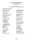
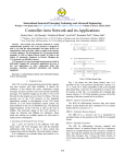
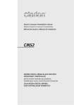
BP5
sPm controL system Base PacKaGe 5
KEY FEATURES
• operation-optimized user
interface
• full flexibility for most advanced measurement techniques
• uncompromising signal quality
• Works with any sPm in any
mode
• future-proof state-of-the-art
hardware
Innovation in surface Spectroscopy and
microscopy systems
SPECS leads the way in state-of-the-art
technology for electron spectroscopy and
scanning probe microscopy.
to our focus on customer support, know-how and
international contacts. Scientists all over the world
can rely on SPECS product quality and be inspired
by the continuous development of new products.
Development of
Nanonis Version 5
SPECS Surface Nano Analysis GmbH
Assembly of a scanning
probe microscope
SPECS has more than 150 employees at its
headquarters in Berlin and its subsidiaries in
the USA and Switzerland. The company also has
sales offices in Spain and BeNeLux, supported
by international sales channels in sixteen
countries. A team of scientists and engineers is
involved in developing and producing scientific
instruments for surface analysis, materials science
and nanotechnology. Since the company has
been founded in 1983, its success is based on a
continuous gain in experience. SPECS scientists are
in close contact to a large number of customers
and scientists around the world. SPECS is your
essential partner in scientific instrumentation due
SPM Control System Base Package 5
Nanonis BP5
tHe eXPandaBLe enGIne for your sPm ProJect
The Base Package 5 of the Nanonis Control
System combines exceptional signal
quality and a flexible, powerful, and userfriendly software interface making it the
ideal choice for the most demanding SPM
applications. The standard for SPM control
systems in its latest version.
Nanonis SPM Control System
the nanonis sPm control system Base Package
5 answers the demand for cutting edge
performance: It combines uncompromising
signal quality due to most advanced hardware
with a fast and reliable control software. from
signal conditioning and ad/da conversion to
fast signal processing via a comprehensive and
operation-optimized graphical user interface, the
nanonis sPm control system provides a powerful
framework that can be further adapted and
Real-time controller RC5
NI-7965R FPGA Card
Clock I/O
Pulse counters
Pulse generators
4x high speed DIO
O
Buffered
transfer
Device control
Device readout
4 x 8 bit DIO
O ports
PXIe bus
Digital filters
Oversampling
Dithering
hrDAC™
Lock-ins
Oscilloscope
FFT
Signal Conversion SC5
ADC/DAC Driver, control logic
Time-critical loops
PI controllers
Data acquisition
Scan generation
State machines
...
Oscillation
control
SC 02 SC 03
NI-8115 RT-system
Core i5 processor
LabVIEW RT OS
OC 01-03
TCP/IP communication
SC 01
Graphical user interface
Data storage
Signal distribution
Optional
precision clock
Host computer
Windows 7 or 8
Dual or quad display
extended with a wide range of add-on modules.
all basic processes such as Z-control, scan control,
data acquisition, data monitoring, spectroscopy,
atomic manipulation and lithography are
included, allowing easy control of most stm and
afm operations. the software adds measurement
methods and complete signal processing
combined with a streamlined user interface,
offering all necessary possibilities in an efficient
workflow for demanding sPm experiments.
18 bit
1 MS/s
8 analog inputs
LP
100 kHz
8 analog outputs
20 bit
1 MS/s
LP
40 kHz
20 bit
1 MS/s
LP
1 MHz
fast analog output
Simplified block diagram
of the Nanonis BP5
Highest signal performance
Fully digital system
The dual-channel
triggering oscilloscope
makes monitoring,
analyzing, and recording
signals an easy task
All analog signals are converted immediately into
the digital domain, where all signal processing is
performed, making them essentially immune to
external noise and crosstalk and ensuring the best
possible signal quality, which is crucial for SPM
applications. In combination with the powerful
software package, signal routing can be adapted
and optimized on the fly with the press of a button
instead of adjusting external hardware cabling. A
fully digital system is also flexible and scalable,
since software adaptations are all that is needed
for rapid custom developments of the system.
Plenty of channels
The generic analog interface provides 48 live
signals: 8 inputs, 8 outputs and 32 internal
signals, with up to 24 signals that can be acquired
simultaneously. This allows the connection of
signals including bias voltage, current, scan
signals, lock-in signals, etc., and combination
of different signals in the digital domain. The
hardware is designed to support up to 24 inputs
and 24 outputs, plus multiple PLLs for AFM
operation, thus allowing operation of even the
most complex measurement set-ups. This large
number of live signals can not only be monitored,
but also all signals are displayed as real world
numbers in floating-point representation, with
assigned SI units for immediate quantitative
results, without the need of additional calibrations
during data analysis.
SPM Control System Base Package 5
Signal analysis and monitoring
All signals can be inspected with the FFT spectrum
analyzer, dual-channel oscilloscope, signal charts,
and history panels. Such fully digital and integrated
software instruments are much more efficient
in use, less invasive, better in performance, and
lower in cost than their external counterparts. The
ability to digitally route live signals to software
instruments during active measurements without
any negative impact on signal quality is truly
invaluable when optimizing the experimental setup, eliminating disturbances and thus improving
the quality of scientific results.
High resolution AD/DA conversion
“There is plenty of room at the bottom”, said
Richard Feynman when he described his vision
of the science that led to nanotechnology.
Enormous resolution is required to reveal the
smallest features, while maintaining a large
dynamic range. The signal frontend of the
Base Package, the Nanonis SC5, uses the latest
advances in AD/DA conversion technology, in
combination with sophisticated digital filtering,
oversampling, and dithering techniques, to
provide the highest resolution.
22-bit resolution with patented
hrDAC™ technology
Adaptive oversampling high
resolution data acquisition
All outputs of the SC5 use 20-bit resolution,
1-ppm precision DACs, the best available on the
market. Just a few years ago, similar performance
on multiple outputs would have been impossible
to realize. The patented hrDAC™ technology
turns these state-of-the-art converters into real
22-bit devices, which in a traditional approach
would fill a rack with single-channel instruments
and cost ten times as much. Measurements
requiring smallest modulations with large offsets
are thus possible without the need for drift- and
error-inducing analog circuits or external mixers
or attenuators. The impressive dynamic range
also eliminates the need for switching gains,
therefore coordinates are absolute over the full
signal and scan range.
A custom-designed input stage allows acquisition
of the weakest analog signals, without
compromises in dynamic range. The signals
are digitized at an early stage with 18-bit AD
converters running at 1 MS/s and then processed
in the digital domain. Adaptive oversampling
allows the ability to always obtain the best signalto-noise performance for a given data acquisition
rate. The user doesn’t need to care about
adjusting time constants, as the data acquisition
automatically provides the best setting.
A 500 µV sweep measured under equal conditions: The
SC5 shows a 16x higher resolution, higher precision,
stability and lower noise compared to the previous
generation
Lowest drift with temperature
stabilization
Scanning probe microscopes require very stable
signals over long measurement times. For this
reason, the SC5 is equipped with a custom
temperature-stabilized, high precision voltage
reference. The reference has a very low inherent
noise and drift. Temperature stabilization
combined with thermal decoupling allows
reduction of the temperature coefficient to below
3 µV/°C and output drift to below 1.5 µV in 12
hours at 0 V.
State-of-the-art optional digital lockin amplifier with 40 kHz bandwidth
DC signals are not the only strength of the
SC5: Each output has a bandwidth of 40 kHz,
and measurement schemes requiring a lockin amplifier (e.g. dI/dV spectroscopy) can be
realized very easily. With 1 MS/s sample rate,
a THD+N larger than 93 dB (18 Vp-p at 1 kHz),
linearity down to below -120 dB, up to 22-bit
resolution, and multiple demodulators, the SC5
outputs offer a powerful measurement tool
also for the most demanding AC experiments
requiring low harmonic distortion and multiple
harmonic demodulation.
5
Lowest output noise floor
When experiments involve energies of a few µeV,
high resolution alone is not the only prerequisite
for a measurement interface: Low noise is
of utmost importance, and the SC5 delivers
impressive performance on both inputs and
outputs. The noise floor of the SC5 lies below
25 nV/√Hz with an output voltage range of ±10
V. Despite its large bandwidth of 40 kHz, the
output noise does not exceed 10 µV RMS at a
measurement bandwidth of 300 kHz, meaning
that the noise contribution of the SC5 is irrelevant
in experimental situations.
Stability at its best: More than a one order of magnitude improvement over the previous generation
High-speed analog output
Designed for providing sawtooth waveforms for
coarse positioning applications, the 9th analog
output of the SC 5 has a bandwidth of 500 kHz.
With the flexible software function generator, the
user can use this additional channel to output
arbitrary periodic waveforms.
A massive reduction in output noise ensures the best
possible measurement results
Lowest 1/f noise outputs
In contrast to broadband noise, which can be
easily filtered, 1/f noise cannot be eliminated
and becomes an issue for experiments requiring
signals to be very stable. The outputs of the
SC5 have been designed keeping this in mind,
leading to a noise level below 750 nV peak-peak
(0.1 – 10 Hz, ±10 V range), or about 223 times
smaller than the maximum output signal.
SPM Control System Base Package 5
Digital inputs and output
32 bidirectional digital lines give sufficient
flexibility for read-out and control of both
Nanonis and external instruments. For high
speed counting applications, four dedicated lines
allow counting rates of up to 100 Mc/s.
7
Nanonis Software Version 5
Most advanced user interface for SPM
The user interface, or in aviatic turns the cockpit,
is a crucial part of the measurement system when
obtaining high quality data in a short time. The
growing complexitiy of nowadays SPM experiments
requires controlling and overlooking of a large
number of parameters, yet even unexperienced
users must be able to operate a complex
instrument safely. The BP5 user interface has been
streamlined in comparison to its predeccessor,
offering a more productive and safe workflow. This
leads to a more modern look and feel, and at the
same time a large number of new functions. Let
your SPM fly without crash landings.
Interactive scan control
The scan control module is interactive and
dynamic, allowing instantaneous control of the
SPM tip in real-time and in any situation. Mouse
button and scroll wheel control allows on the fly
adjustments and data visualization optimization.
By this, it is possible to zoom in, adapt scan frame
parameters and paste multiple scanned images
to the background for reference. With up to seven
scan windows it is easy to keep an overview over
all acquired data. Arbitrary rotation of the scan
plane on any of the X,Y and Z axis even allows to
scan on the “walls” of high aspect-ratio samples.
Advanced multipass techniques with
scripting functions
Many experimental techniques require the tip to
be scanned multiple times on the same line while
acquiring a scan image. The Nanonis multi-pass
function allows multiple passes with different
setpoints, speeds, bias voltages, at constant
tip-to-sample distance, constant Z, or with any
other parameter recorded during the previous
pass. Multiple passes can be time consuming
when taking high resolution images, therefore
optimizing the time for each scanned image
can become crucial. The multipass function is
therefore coupled with a scripting function, which
makes it possible to run experiments like KPFM
at real-time and deterministic speed just with a
few script entries, and thus reduces time losses
without the need for complex programming.
The scan control module
gives the user a complete
overview of the sample
and full control of the SPM
tip at any time
Advanced 2D and 3D spectroscopy
User Interface Z-Controller
Advanced spectroscopy modules provide a set of
flexible routines for experiments on a point, line,
grid, or a cloud of points. Additionally, a “point
and shoot” mode, where the user can interactively
perform any experiment at a mouse click, and a
fast spectroscopy mode allow precise and timeefficient spectroscopic measurements while
scanning an image. Spectroscopy modules are bias
spectroscopy, Z-spectroscopy, and generic sweep
where any output or parameter can be swept
while any number of other selected channels
can be recorded. Each module is designed to
optimize precision and time requirements of the
experiments. In the case of bias spectroscopy, a
bias-dependent measurement resolution reduces
the required measurement time per acquired
spectroscopy curve, while disabling of the dI/dV
AC modulation signal when in feedback improves
reliability when determining the exact Z-position.
In the same way, in the Z-spectroscopy module,
a dedicated safety loop reduces the risk of tip
crashes. In addition to the already implemented
modules, any user-defined experiment written in
LabVIEW can be integrated into the spectroscopy
functionality of the Nanonis SPM Control System,
by using the Programming Interface.
Versatile Z-controller
The distance between tip and sample can be
controlled by any signal or combination of signals.
Quantitative parameters allow the application
of control theory models and yield a further
understanding of the tip-sample interaction. The
user-configurable Z-controller allows on-the-fly
switching between settings such as input signal
and feedback parameters. And when it takes days
to get the first high quality image, a tip crash is
the last thing a researcher wants to happen. The
SafeTip™ function takes care of retracting the tip
should a potentially harmful event be detected.
SPM Control System Base Package 5
Not only is this function very fast, and designed
to reduce creep-induced drift, but it also gives
the user a variety of choices what to do in such an
event, ranging from engaging coarse motion to
retract the tip further, to a scan resume function
which limits data losses while scanning.
Easy expansion through add-on
modules
The modularity of the software is a key advantage
in cost optimization: Additional software modules
can be added when experimental needs require
them. Even modules which are not available
at the time of purchase of the Base Package,
can be purchased at a later stage, making the
instrument highly future-proof. The addition of
new modules does not require any hardware or
software installation, and can be performed in a
very short time. In addition to the modules listed
above, pulse counters, a large number of coarse
approach motor control modules for commercial
and home-built microscopes and other dedicated
modules are available on request.
Oscillation control: A new cockpit for
AFM experiments
While a few years ago there was only a handful
of AFM measurement modes, nowadays new
measurement environments and techniques
ask for a plethora of often sophisticated new
measurement modes. The control center for
all this is the Oscillation Control of the Nanonis
software. Growing sophistication requires more
effective user guidance, therefore the AFM cockpit
has been redesigned in order to counteract the
growing complexity of AFM experiments, offering
a more logical approach and a better overview.
With a few clicks the oscillation controller can be
transformed form a simple high-performance lockin for intermittent contact mode measurements,
to a full-featured controller for multi-excitation
and multi-frequency FM-AFM.
9
fully automated TrueDissipation® algorithm
(developed at/with McGill Universityreference)
determines the amount of apparent damping, and
corrects measured dissipation data accordingly,
allowing for a much more precise determination
of
nonconservative
interaction
forces.
Advanced signal processing: lock-in
The same advanced filtering techniques used for
the oscillation control are available for the lock-in
module, boosting dynamic reserve, and improving
noise rejection performance. Combined with
the exceptional signal performance of the SC5,
the new lock-in module becomes an even more
powerful tool for high-resolution measurements
like scanning tunneling spectroscopy and
transport.
Advanced signal processing:
Multifrequency and
multidemodulator filtering
TrueDissipation®
FM-AFM measurements allow discerning between
conservative and nonconservative tip-surface
interaction forces, the latter being determined by
recording the excitation signal of the AFM probe.
In many cases, however, the resulting dissipation
data show artefacts, which cannot be related to
tip-sample interaction. Most of these artefacts,
are attributed to “apparent damping”, which
mostly originates from energy dissipated into the
measurement system, thus making quantitative
and
therefore
scientifically
meaningful
dissipation measurements impossible. The
Multifrequency techniques have shown that
significant physical information can be extracted
from an apparently simple-looking AFM probe
oscillation signal. The new oscillation control
offers multiple independently configurable
demodulators, all seamlessly integrated into the
Nanonis signal handling. Performing complex
multifrequency measurements is now possible
with just a few clicks, and without requiring
additional hardware. Small amplitudes of
harmonics or noisy signals due to difficult
environments demand high performance signal
recovery capabilities. The oscillation control
offers improved filtering techniques with better
stopband attenuation, user-selectable slopes,
individual configuration for each harmonic, and all
this compatible with the existing OC4 hardware.
User Interface
Oscillation Control
Add-on module LabVIEW
Programming Interface
Competitive advantage in research is often based
on the modification of an instrument that allows
the researcher to perform experiments in a way
nobody else has done before. This is where the
LabVIEW Programming Interface steps in: to
give you the building blocks to design your own
experiment. The LabVIEW Programming Interface
consists of libraries to access the controls and
functions of the graphical user interface. It is used
to automate experiments, sequences, calibration
routines and experimental procedures. Polling of
parameters and signals at high rates allows for
supervision and alarm settings, and many other
features. Instead of using a simple scripting
language, or a dedicated language, the Nanonis
SPM Control System provides full access to all
the features provided with LabVIEW: graphs,
database access, convenient data handling, TCP/
IP, GPIB, RS232, USB access to other instruments,
signal analysis functions and much more.
Add-on modules:
Advanced oscilloscope and FFT
SPM experiments often require acquisition of
time-dependent signals, with typical time scales
ranging from microseconds to several minutes.
A new oscilloscope and FFT module gives access
to data acquisition with up to 1 MS/s, variable
acquisition time, and trace lengths of up to 1 million
points. The high precision and low noise inputs of
the SC5 allow acquisition of high dynamic range
signals without the need of gain switching, while
exact timing is guaranteed by a fully configurable
triggering system (with pre-triggering option). In
parallel to precise time-resolved measurements,
the FFT function offers very high frequency
resolution down to the mHz range.
SPM Control System Base Package 5
Add-on modules: Scripting
For experiments where exact timing is crucial, the
scripting module becomes the ideal companion
for the Nanonis Programming Interface: Scripts
are executed on the real-time system in a timedeterministic manner, improving (reducing)
the time response by a factor of 100. Scripting
can be fully integrated with time consuming
measurements like Kelvin Probe and Multipasstechniques, thus reducing dwell times and
improving measurement precision.
Add-on modules for special applications
There is a variety of modules for special
applications like Atom tracking, Kelvin controller,
Interferometer controller, Function Generator,
PI Controller. In addition to the modules listed
above, pulse counters, a large number of coarse
approach motor control modules for commercial
and home-built microscopes and other dedicated
modules are available on request.
Constantly more add-on modules to
come
A large number of other new functions and improvements, ranging from improved data display
to subgrid spectroscopy have been implemented
with the goal to give researchers an even more
powerful and effective tool for cutting edge scientific research. As demonstrated in the last decade,
the Nanonis SPM Control System has continuously
evolved, giving researchers access to new functionality and features. The same philosophy will
continue to exist with the BP5, meaning that many
new functions will be added in the years to come.
Future-proof state-of-the-art
hardware Base Package 5
11
Signal Conversion SC5
Real-time Controller RC5
The electronic mainboard of the SC5 is a
showcase for the best available active digital and
analog electronic components on the market.
Cheaper solutions leading to compromises
have been discarded from the beginning, since
only by meticulously choosing the best suitable
components down to each single resistor, can the
exceptional performance of the SC5 be achieved.
The SC5 is powered by a linear power supply.
Switching power supplies or DC/DC converters
are not used anywhere in the instrument. Despite
being equipped with a linear power supply, there
is no need to manually adjust the line voltage to
local circumstances: An intelligent circuit detects
the line voltage and automatically configures
the power transformer inputs. An auxiliary
power supply is available for powering external
instruments like e.g. preamplifiers. With its lownoise, preregulated ±15 V voltage with up to 300
mA current delivery capability, it makes external
power supplies unnecessary.
The “brain” of the Nanonis Base Package is the
real-time controller RC5. By using the latest FPGA
and CPU technology, the RC5 provides enough
speed, connectivity and processing power for the
most demanding tasks. Modularity doesn’t stop
there either: Both FPGA and real-time modules
are easily exchangeable, and can be updated
should significantly faster modules be available
in the future. When a new experiment is started,
often not all requirements are already known in
detail. This is no problem with the SC5 and its
real-time controller RC5. The addition of one
or more Nanonis Oscillation Controllers (OC4),
which extends the frequency range to 5 MHz, is
straightforward, should a larger signal bandwidth
be required. Communication, triggering and
control of additional external instruments
is an easy task thanks to the various digital
communication options of the RC5.
Hardware add-ons for a
modular control system
Modularity of the Nanonis SPM control system
means that the hardware required for a given
experimental situation can be tailored to the
users‘ needs. This is the most flexible and at the
same time cost-effective solution, and offers
the best performance since each instrument is
highly optimized. Hardware add-ons include the
oscillation controller, high-voltage amplifiers,
piezo drivers, and adaptation kits for commercial
microscopes.
Oscillation Controller with PLL Nanonis OC4 and OC4 Dual
The Oscillation Controller (OC4) with digitally
integrated PLL adds dynamic AFM capabilities
to the Nanonis Control System. The z-feedback
can regulate on any signal coming from the
mechanical resonator with any predefined
SafeTip™ conditions. Imaging modes include
among others: non-contact AFM, intermittent
contact mode, phase imaging, dissipation. With
an input bandwidth of 5 MHz, the OC4 can
operate any type of cantilever, tuning fork, needle
sensors, etc. and their harmonics. And, it can be
used as a powerful digital lock-in amplifier.
High Voltage Amplifiers Nanonis HVA4
The Nanonis HVA4 is a low noise, six-channel
high-voltage amplifier specifically designed
for nanopositioning applications using piezo
elements. Three different models with maximum
output voltages of ±140 V, ±220 V or ±400 V
let the user choose an optimal setup for his
application. With differential inputs and a noise
spectrum density below 1 μV/√Hz at 300 Hz
at gain 40 (input shorted), the HVA4 sets the
standard for low-noise HV applications. The
SNR of the HVA4 is so large that even with a
10 μm Z-range piezo tube, the noise level in Z
corresponds to less than 2 pm (RMS), far below
the corrugation of the sample.
Piezo Drivers Nanonis PMD4
The Nanonis PMD4 is a high performance piezo
motor driver, designed to drive piezo positioners
with a very wide range of specifications. Owing to
its patented output drive technology, the PMD4
is perfectly suited for driving piezo positioners in
SPM applications, even under the most difficult
conditions, e.g. at very low temperatures or with
large capacitance piezo motors. The PMD4 is
available with eight or sixteen output channels
and a single waveform generator, or with eight
output channels and two waveform generators.
It can be remotely controlled in combination with
a Nanonis SPM control system over its digital
SPM Control System Base Package 5
interface, or with the included handset. the
amplitude of the output waveform can be varied
continuously between 0 and ±400 v, and its
frequency continuously between 1 Hz and 20 kHz.
High resolution images measured
with the nanonis BP5
Atomically resolved 3D STM image of graphene moiré
on Ru(0001). Scan size: 16.5×16.5 nm2. Tunneling parameters: IT= 1 nA, UT= 0.5V.
Piezo drivers nanonis Pd5
Graphene/Ir(111): Switch
between STM (top) and
nc-AFM (bottom) modes
“on-the-fly”. Scan size:
5×5 nm2. Scanning
parameters: UT= +30mV,
IT=1nA, ∆f= -475mHz.
the nanonis Pd5 combines the functionality of
the Hva4 and of the Pmd4 into a single enclosure.
five low-noise high voltage channels with the
same specifications as the Hva4 are combined
with eight outputs for driving low-capacitance
piezo motors with software or handset control.
(a)
adaptation kits for use with
commercial microscopes
numerous adaptation kits are available to
interface the nanonis sPm control system with
most types of commercial microscopes including
omicron, veeco (Bruker), JeoL, createc, rHK
and unisoku. the original sPm cables connect
directly to the pin-compatible interfaces, making
a change of the control system extremely simple.
(b)
Constant height SPM images of graphene/Ir(111).
(a) ∆f channel, range: -2.66 Hz … -2.46 Hz; (b) IT channel,
range: -1.88 nA … +2.43 nA. Scan size: 4.3 × 4.3 nm2. Bias
voltage was changed from +50 mV to -50 mV in the middle of the scan area.
13
Specifications
Technical data
Analog Inputs
(all specifications for ±10 V input range)
General
Content of Delivery
Real-time controller RC5,
Signal conversion SC5, software and license, unlimited
updates and support for one
year, host computer (Option)
Cases
Stackable benchtop cases, full
metal enclosure
Operating
Temperature
+5° C to +35° C
Compliance
CE
Warranty
One year parts and labor (EU:
two years) on defects in material and workmanship
Documentation
User manual describing
hardware and installation,
online user manual for
graphical user interface
RC5
Hardware Interface
8 x BNC connectors,
differential
Differential Input
Voltage Range
±10 V
Differential Input
Impedance
2 MΩ
Analog Bandwidth
DC – 100 kHz (-3 dB),
5th-order Butterworth
low-pass filter
AD-converter
18-bit, no missing codes,
1 MS/s
Effective Resolution
20-bit @ 60 kS/s,
24-bit @ 240 S/s
(oversampling)
INL
±2 LSB typical
DNL
±1 LSB typical
Input Noise Density
< 150 nV/√Hz @ 10 kHz,
< 650 nV/√Hz @10 Hz
Measurement Noise
< 100 µVrms @ 1 MS/s,
< 25 µVrms @ 60 kS/s,
< 6.5 µVrms @ 240 S/s
Dimensions
32.5 x 28 x 21 cm
Weight
7.8 kg
12 h-Drift
Power Supply
Built-in universal power
supply, max. 200 W,
100 – 240 V, 50 - 60 Hz
< 80 µV (< 100 µV) @ 0 V
(@ 9.9 V)
THD+N, 9 V Input
Signal
Real-time System
NI PXIe-8115 real-time system
with Intel Core i5 CPU
2.5 GHz, 2 GB RAM
> 120 dB @ 100 Hz,
> 95 dB @ 1 kHz,
> 70 dB @ 10 kHz
Operating System
NI LabVIEW Real-Time OS
FPGA Card
NI PXIe-7965R
Connectivity
3 x SC5 max., 3 x OC4 max.
Total of max. 4 frontends
SC5
Dimensions
R 32.5 x 28 x 7 cm
Weight
4.2 kg
Power Supply
Built-in linearly regulated
power supply, toroidal
transformer, automatic line
voltage detection. Max. 51 W,
100 – 240 V, 50 - 60 Hz
Electrical GND
SPM Control System Base Package 5
10 kΩ AGND to chassis,
decoupled from RC5
Analog Outputs
(all specifications for ±10 V output range)
Hardware Interface
8 x BNC connectors,
referenced to AGND
Output Voltage Range
±10 V into 1 kΩ or larger
(0 to +10 V with internal jumper per channel)
Output Impedance
<1 Ω, short circuit safe
Analog Bandwidth
DC – 40 kHz (-3 dB),
5th – order Butterworth
low-pass filter
DA Converter
20-bit, 1-ppm precision,
1 MS/s
Effective Resolution
22-bit, patented hrDAC™
technology with active glitch
compensation
15
Analog Outputs
(all specifications for ±10 V output range)
Graphical User Interface
Operating System
Windows XP/Vista/7/8
Windows 7 64-bit recommended
Min. Requirements
Intel Core Duo 1.5 GHz or
equiv., 2 GB RAM, 100 GB HD,
two 19” screens with at least
1280 x 1024 pixels
12h-Drift
< 1.5 µV (< 25 µV)
@ 0 V (@ 9.9 V)
Recommended
Configuration
THD+N, 9 V Output
Signal
> 93 dB @ 100 Hz, > 93 dB
@ 1 kHz, > 79 dB @ 10 kHz
Intel Core i5 2.5 GHz or
equiv., 4 GB RAM, 1 TB HD,
two 21” screens with 1600 x
1200 or 1920 x 1200 pixels
License
Unlimited in time,
bound to RC5
Documentation
Online help, F1 for context
sensitive help, tip strips for
each control element, printed
hardware user manuals with
operation instructions for
related software modules
Settings
Configuration
For every session directory/
user, settings, parameters and
screen layouts
INL
< ±2 LSB max. < ±1 LSB typical
DNL
< ±1 LSB max. < 0.5 LSB
typical
Output Noise Density
< 25 nV/√Hz @ 100 Hz,
< 75 nV/√Hz @ 1 Hz
Output Noise
< 200 nVrms (0.1 – 10 Hz),
< 10 µVrms (10 Hz – 300 kHz)
Digital Lines
Ports
4 x 8 lines on four D-sub
9 female connectors
Direction
Input or output for each line
Signal
3.3 V TTL, max. 25 mA per line
Maximum Sampling
Frequency
500 kHz
Signals
High Speed Digital Lines
Ports
4 x inputs and 4 x outputs on
SMB male connectors
Signal
3.3 V TTL, max. 33 mA per line
Maximum Sampling
Frequency
200 MHz
Clock
Ports
1 x input, 1 x output for active
clock source
Frequency
10 MHz, square wave, 3.3 V
Accuracy
± 50 ppm (standard clock),
± 4 ppm (optional OCXO)
Signals
48 signals (inputs, outputs
and internal signals), up to
24 simulteneous signals for
data display and acquisition
Data Transfer
Via TCP/IP, 2 kS/s default,
up to 20 kS/s
Representation
32-bit floating point,
real world physical units
SPECS Surface Nano Analysis GmbH
Voltastrasse 5
13355 Berlin / Germany
www.specs.com
T +49 30 46 78 24-0
F +49 30 46 42 083
E [email protected]