1
Products: SMIQ
Fast Remote Control for
R&S SMIQ
Vector Signal Generators
Short setting times are among the most important criteria when it comes to choosing the right signal generator,
especially in production. With its extremely short setting times for frequency (<3 ms) and level (<2.5 ms), the R&S
SMIQ Vector Signal Generator family easily meets the requirement. In addition, SMIQ provides two special modes
where setting times can be further reduced, Fast Restore mode and List Mode.
This Application Note decribes both modes and gives some application examples.
Subject to change – Dr. René Desquiotz 08.2002 – 1GP55_0E
Fast remote control of SMIQ
Contents
1
2
3
4
5
Overview ...............................................................................................................................................2
SMIQ Fast Restore Mode .....................................................................................................................2
Working principle ............................................................................................................................2
Operation ........................................................................................................................................3
Application examples ......................................................................................................................5
SMIQ List Mode ....................................................................................................................................9
Working principle ............................................................................................................................9
Operation ........................................................................................................................................9
Application examples ....................................................................................................................12
References .........................................................................................................................................15
Ordering information ...........................................................................................................................15
1 Overview
Short setting times are among the most important criteria when it comes to choosing the right signal
generator, especially in production. With its extremely short setting times for frequency (<3 ms) and level
(<2.5 ms), the R&S SMIQ Vector Signal Generator family is best suited to meet the requirement. In
addition, SMIQ provides two special modes where the setting times can be further reduced.
The Fast Restore mode is a special feature for remote controlling the generator. Device settings can be
saved and recalled very quickly via the IEC/IEEE bus using special commands. The Fast Restore
commands directly address the instrument modules, the database of the SMIQ is bypassed, leading to a
very high setup speed. Frequency and level settings can be performed in less than 800 µs. The Fast
Restore mode is not restricted to frequency and level settings; nearly all RF and general device
parameters can be set.
1
The LIST mode provides even faster frequency and level settings (<500 µs ). A sequence of freely
selectable frequency and level points can be executed, either automatically or triggered by an external
device or the internal baseband section. Triggering via the IEC/IEEE bus is also supported.
This Application Note explains both the Fast Restore mode and the LIST mode, and gives some
application examples.
2 SMIQ Fast Restore Mode
Working principle
Device settings can be saved and recalled very quickly via the IEC/IEEE bus using the commands
described below. Up to 4000 memory locations are available, depending on the SMIQ version and the
options installed.
In contrast to the normal SAVE/RECALL function, only the setting data of the modules is stored in the
Fast Restore mode. Restoring by means of the ':SYSTem:SREStore' or '!..' command has an immediate
effect on the modules. The database (which stores all entries and delivers the display data) is bypassed.
The result is a very high setup speed.
The Fast Restore commands have an effect on almost all RF and general device settings (see Table
2.1)
1
1GP55_0E
For f > 3.3 GHz the setting time is less than 700 µs.
2
Rohde & Schwarz
Fast remote control of SMIQ
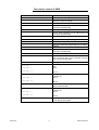
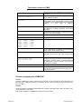
Table 2.1:
Device settings in Fast Restore mode.
Device settings supported by Fast Restore:
Device settings not supported by Fast
Restore:
•
Frequency including reference oscillator
•
baseband signal of digital modulation and
digital standards
•
Level including mech. switched attenuator,
user correction and ALC modes
•
Settings for fading, noise and distortion
•
•
Analog modulation
•
Functions not affecting the RF output signal,
eg commands under :SYSTem:... or
:UNIT:... (except for SYSTem:PRESet)
Vector modulation
•
Sweep
•
Switch-on/off digital modulation, ARB mode
or digital standards
•
List mode
•
Memory sequence
•
Switch on/off fading, noise or distortion
•
LF generator and LF output
Fast Restore does not affect the baseband modules. If a baseband module is switched on before using
RESTORE commands, it will remain on until it is explicitly switched off by a normal IEC/IEEE command.
Fast Restore can however switch from CW to modulated signals and back by turning on or off the I/Q
modulator, without setting baseband modules. So it is possible to change baseband settings with normal
commands and then use the same RESTORE settings again. This works with 3GPP, IS-95 downlink,
ARB mode and vector modulation, for example. GSM/EDGE, however, requres different RESTORE
states because the powerramping is done partly by RF modules, as is the case for all modulations
where powerramping (indicated by PRAMP) is active.
Operation
Commands
:SYSTem:SSAVe 1...n
(n being the number of available memory locations)
Saves the current device setting at the memory location indicated.
:SYSTem:SREStore 1...n
(n being the number of available memory locations)
Loads a device status that was stored using the :SYSTem:SSAVe command (RESTORE).
! <least significant byte> <most significant byte>
This command has the same effect as the:SYSTem:SREStore command. The setting time however is
300 µs shorter. It is optimized for highest speed and does not comply with the SCPI syntax regulations.
Exactly 3 bytes are transmitted including the '!' (which is the identifier of this command). With the last
byte, EOI has to be activated as delimiter.
The memory location is binary-coded in the 2 bytes indicated.
1GP55_0E
3
Rohde & Schwarz
Fast remote control of SMIQ
Example:
RESTORE at memory location 268 (-> 010C hex) corresponds to the following binary command:
0010 0001
'!'
0000 1100
0000 0001
hex 0C
hex 01
Binary-coded bytes usually cannot be written as printable ASCII characters. When programmed in C, the
above command has the following form:
char sendstring[3] = {'!', 0x0C, 0x01}
In BASIC, the command string to be output is as follows:
'!' + CHR$(12) + CHR$(1)
(The pros for CHR$ are decimal numbers, therefore 12 for 0C hex.)
Since binary-coded bytes can also have the value of the LF (line feed) character which is interpreted as
a
delimiter,
switch
over
to
'only
EOI'
as
delimiter
by
selecting
':SYSTem:COMMunicate:GPIB:LTERminator EOI' prior to using this command.
Call-up and termination of operating mode
After a RESTORE, the database no longer reflects the device setting which means that
•
the displayed values are no longer relevant,
•
the desired result is not obtained by a query of setup values.
•
normal setting commands may not be executed properly
It is therefore recommended either to use the *RST command or to store the device setting prior to using
the first RESTORE command by means of the :SYSTem:SSAVe n command and to restore it after the
last RESTORE command using :SYSTEM:SRESTore n. The database and the device setting will then
match again.
No other commands are required to activate or deactivate this mode.
Alternative use with other IEC/IEEE-Bus commands
The alternative use of the RESTORE commands (':SYSTem:SREStore' or '!..') and normal
IEC/IEEE-bus commands is
•
useful with digital modulation:
First, the baseband signal is configured by means of normal commands and digital modulation is
switched on. Then, digital modulation can be switched on/off using the RESTORE commands.
•
possible for all commands that do not affect the RF output signal (eg
:UNIT:...),
•
normally not possible for all the functions listed in the left column of Table 2.1.
:SYSTem:...,
In case of doubt, we recommend testing.
1GP55_0E
4
Rohde & Schwarz
Fast remote control of SMIQ
Synchronization signal
In Fast Restore mode a synchronization signal is available at the rear-panel BLANK connector to
synchronize other devices.
The BLANK signal is high during settling of the RF output signal and low in the settled state. The BLANK
polarity can be changed in the menu UTILITIES → AUX I/O.
Additional recommendations
•
If the mechanically switched attenuator is switched over by a RESTORE command, the setting time
increases by 15 ms. This can be avoided by setting attenuator mode FIXED or ELECTRONIC for
interruption-free level setting prior to storing the setting. To get the desired level setting range, set
the level to the highest desired value in attenuator mode AUTO, then switch to attenuator mode
FIXED or ELECTRONIC (:OUTPut:AMODe FIXed or ELECtronic). For details of the SMIQ’s level
setting modes see reference [4].
•
The time for switching on or off I/Q modulation can also be decreased using the fast I/Q transition
mode (:SOURce:DM:IQ:TRAN FAST). In this mode the I/Q modulator is never switched off, the
CW signal is generated by a baseband signal with constant voltage (UI = 0.5 V, UQ = 0 V). As the
spectral purity of the CW signal is slightly decreased, this mode should only be used when fast
transitions between I/Q modulated and CW signals are required. The fast transition mode works
with VECTOR MOD, DIGITAL MOD and DIGITAL STD (standards). However, the mode makes no
sense when changing the baseband signal takes more time than switching the I/Q modulator, as for
example with WCDMA/3GPP or ARB mode. Note that the fast I/Q transition mode requires a
baseband module to be set, which is only possible with normal IEC/IEEE commands. In most cases
RESTORE commands will be faster than the fast I/Q transition mode.
•
Since the module setting depends on the temperature of the unit, any temperature variation of more
than 5°C should be avoided between storage and call-up, to ensure the accuracy of the unit.
Application examples
Switching between CW and modulated (WCDMA/3GPP)
Problem:
Provide a WCDMA/3GPP signal and afterwards a CW signal in the 3GPP downlink band (e.g. an
interfering signal for a receiver test). The generator shall step through the entire band in 5 MHz steps.
The signal level shall be –10 dBm.
Note: Options SMIQB20, SMIQB11 and SMIQB45 are required for this example.
Solution:
The most time-consuming process is the calculation of the 3GPP signal. Without Fast Restore, this has
to be done every time the 3GPP state is switched on. Therefore it is our goal to do this calculation only
once. We first save the Fast Restore states with CW signals. Afterwards we calculate the 3GPP signal
with normal IEC/IEEE commands and save the Fast Restore states with the modulation active. Then we
run through the frequencies and switch between CW and 3GPP signals with RESTORE commands. This
does not change the 3GPP state, only the I/Q modulator is switched on or off. Therefore we avoid the
time-consuming recalculation of the 3GPP signal. As the initial baseband state (3GPP) is on, we should
also terminate with a 3GPP signal running.
The commands for the entire procedure are as follows:
1GP55_0E
5
Rohde & Schwarz
Fast remote control of SMIQ
Command
Remarks
Preparation
*RST;*CLS
Sets the instrument to a defined state. Note that *RST
switches off the RF output.
:SOUR:POW –10
Sets the RF level to –10 dBm
:OUTP:AMOD FIX
Sets attenuator mode FIXED, for uninterrupted level
settings in a range of 20 dB. Prevents attenuator
switching when the modulation is turned on or off.
:SOUR:POW:ALC OFF
:SOUR:POW:ALC:SEAR OFF
Sets ALC mode TABLE.
uninterrupted level setting
:SOUR:W3GP:SETT:TMOD:BST M1CH64
Sets the parameters for the 3GPP test model
:SOUR:FREQ 2.1125E9
Sets the carrier frequency to 2112.5 MHz (lower end
of the 3GPP downlink band)
:OUTP:STAT ON
The RF output has to be switched on before storing
the Fast Restore states. (*RST sets the output to
OFF)
:SYST:SSAV 1
Saves the first CW setting
:SOUR:FREQ 2.1175e9
Sets the carrier frequency to 2117.5 MHz
:SYST:SSAV 2
Saves the second CW setting
Recommended
for
(continue)
:SOUR FREQ 2.1675e9
Sets the carrier frequency to 2167.5 MHz (upper end
of the 3GPP downlink band)
:SYST:SSAV 12
Saves the last CW setting
:SOUR:FREQ 2.1125e9
Sets the carrier frequency to 2112.5 MHz (lower end
of the 3GPP downlink band)
:SOUR:W3GP:STAT ON
Calculates and turns on the 3GPP signal
:SYST:SSAV 13
Saves the first 3GPP signal setting (2112.5 MHz)
:SOUR:FREQ 2.1175e9
Sets the carrier frequency to 2117.5 MHz
:SYST:SSAV 14
Saves the second 3GPP signal setting (2117.5 MHz)
(continue)
:SOUR:FREQ 2.1675e9
Sets the carrier frequency to 2167.5 MHz (upper end
of the 3GPP downlink band)
:SYST:SSAV 24
Saves the last setting with 3GPP on
:SOUR:FREQ 2.1125e9
:SYST:SSAV 25
Sets the initial (and final) state. This is useful to match
user interface and hardware state after running a Fast
Restore sequence. Note that the modulation is active
in this state.
Running the sequence
1GP55_0E
:SYST:SRES 1
:SYST:SRES 2
Runs through the CW states (I/Q modulator off)
state 1
state 2
:SYST:SRES 12
...
state 12
:SYST:SRES 13
Runs through the states with 3GPP signal (I/Q
modulator on)
state 13
6
Rohde & Schwarz
Fast remote control of SMIQ
...
state 24
initial state
:SYST:SRES 24
:SYST:SRES 25
The following settings (among others) are stored in the Fast Restore states:
1
2
...
12
13
14
...
24
25
2.1125 GHz; -10 dBm; I/Q modulator off
2.1175 GHz; -10 dBm; I/Q modulator off
2.1675 GHz; -10 dBm, I/Q modulator off
2.1125 GHz; -10 dBm; I/Q modulator on
2.1175 GHz; -10 dBm; I/Q modulator on
2.1675 GHz; -10 dBm, I/Q modulator on
2.1125 GHz; -10 dBm; I/Q modulator on
Note: the Fast Restore states can be restored in any order. You should only terminate the sequence with
a Fast restore state where the I/Q modulator is switched on, in this case state 25.
Switching between different digital modulations and CW
Problem:
Same as before, this time with an additional run with a cdmaOne (IS-95) signal.
Note: Options SMIQB20, SMIQB11, SMIQB42 and SMIQB45 are required for this example.
Solution:
Similar to example 1. To add the IS-95 signal, we use additional normal IEC/IEEE commands.
Command
Remarks
Preparation
1GP55_0E
*RST;*CLS
Sets the instrument to a defined state. Note that *RST
switches off the RF output.
:SOUR:POW –10
Sets the RF level to –10 dBm
:OUTP:AMOD FIX
Sets attenuator mode FIXED, for uninterrupted level
settings in a range of 20 dB. Prevents attenuator
switching when the modulation is turned on or off.
:SOUR:POW:ALC OFF
:SOUR:POW:ALC:SEAR OFF
Sets ALC mode TABLE.
uninterrupted level setting
:SOUR:W3GP:SETT:TMOD:BST M1CH64
Sets the parameters for the 3GPP test model
:SOUR:IS95:MODE FLIN18
:SOUR:IS95:PRES
Sets the parameters for the cdmaOne signal (in this
case a predefined 9 code channel scenario)
:SOUR:FREQ 2.1125E9
Sets the carrier frequency to 2112.5 MHz (lower end
of the 3GPP downlink band)
:OUTP:STAT ON
The RF output has to be switched on before storing
the Fast Restore states. (*RST sets the output to
OFF)
7
Recommended
for
Rohde & Schwarz
Fast remote control of SMIQ
:SYST:SSAV 1
Saves the first CW setting
:SOUR:FREQ 2.1175e9
Sets the carrier frequency to 2117.5 MHz
:SYST:SSAV 2
Saves the second CW setting
(continue)
:SOUR FREQ 2.1675e9
Sets the carrier frequency to 2167.5 MHz (upper end
of the 3GPP downlink band)
:SYST:SSAV 12
Saves the last CW setting
:SOUR:FREQ 2.1125e9
Sets the carrier frequency to 2112.5 MHz (lower end
of the 3GPP downlink band)
:SOUR:W3GP:STAT ON
Calculates and turns on the 3GPP signal
:SYST:SSAV 13
Saves the first 3GPP signal setting (2112.5 MHz)
:SOUR:FREQ 2.1175e9
Sets the carrier frequency to 2117.5 MHz
:SYST:SSAV 14
Saves the second 3GPP signal setting (2117.5 MHz)
(continue)
:SOUR:FREQ 2.1675e9
Sets the carrier frequency to 2167.5 MHz (upper end
of the 3GPP downlink band)
:SYST:SSAV 24
Saves the last setting with 3GPP on
As we mix normal and RESTORE commands, it is
better to terminate with a *RST command. Therefore
we do not save an initial state.
Running the sequence
:SYST:SRES 1
:SYST:SRES 2
Runs through the CW states (I/Q modulator off)
state 1
state 2
:SYST:SRES 12
...
state 12
:SYST:SRES 13
Runs through the states with 3GPP signal (I/Q
modulator on)
state 13
:SYST:SRES 24
...
state 24
:SOUR:IS95:STAT ON
Switches on the cdmaOne signal. The 3GPP signal is
turned off automatically.
:SYST:SRES 13
Runs through the states with cdmaOne signal (I/Q
modulator on)
state 13
:SYST:SRES 24
...
state 24
*RST;*CLS
1GP55_0E
Resets the unit to make sure that database and
device settings match again.
8
Rohde & Schwarz
Fast remote control of SMIQ
3 SMIQ List Mode
Working principle
A sequence of predefined frequency and level points is executed in LIST mode, similar to a sweep. In
contrast to a sweep, a list with freely selectable pairs of values (frequency and level) can be generated.
The specified range of the frequency comprises the entire adjustable frequency range of the instrument.
The specified range of the level covers a 90 dB range. If the permissible variation range is exceeded, the
level accuracy decreases. If the level range exceeds 20 dB, SMIQ switches to attenuator mode
ELECTRONIC. Otherwise, attenuator mode FIXED is used.
Stepping through the list can be triggered by an external TTL signal. The LIST mode allows even faster
level or frequency variations than the Fast Restore mode. However, LIST mode includes only the
parameters RF level and RF frequency.
Operation
Creating a list
Up to 10 lists can be created. The total number of possible list entries in all lists depends on the SMIQ
version and the options installed. The number of remaining entries is indicated in the menu LIST →
FUNCTION → EDIT/VIEW. The command :SOUR:LIST:FREE? returns two values, first the free memory
(in numbers of entries), then the number of entries already used.
Each list is identified by a separate name and selected via this name. Each list consists of a frequency,
power and dwell content. The dwell time is set once per list. The number of entries for frequency and
level must be equal. However, if a parameter has just one value throughout the entire list, it is sufficient
to set this value once.
Note: After generating, modifying or changing a list in the LIST mode, the LEARN function must be
executed to ensure that the new settings are transferred to the hardware (IEC-bus short command:
LIST:LEAR).
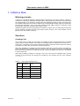
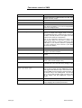
Table 3.1
1GP55_0E
LIST mode; Example of a list
Index
Frequency
Level
0001
100 MHz
0 dBm
0002
575 MHz
13 dBm
0003
235 MHz
7 dBm
:
:
:
0100
333 MHz
5 dBm
:
:
:
9
Rohde & Schwarz
Fast remote control of SMIQ
Running LIST mode
The following LIST-operating modes are available:
AUTO
Run from the beginning to the end of the list with automatic restart at the
beginning. If another mode was activated prior to the AUTO operating mode,
continuation is made from the current index.
IEC/IEEE-bus commands:
:SOUR:FREQ:MODE LIST
:SOUR:LIST:MODE AUTO
:TRIG:LIST:SOUR AUTO
SINGLE
Single run from the beginning to the end of the list. If SINGLE is selected,
the run is manually executed with the function EXECUTE SINGLE LIST .
IEC/IEEE-bus commands:
:SOUR:FREQ:MODE LIST
:SOUR:LIST:MODE AUTO
:TRIG:LIST:SOUR SING
STEP
Step-by-step manual processing of the list. Activating STEP stops a list
running and the cursor wraps to the indication value of CURRENT INDEX.
The list can now be controlled upwards or downwards in discrete steps
using the rotary knob or the numeric keys.
IEC/IEEE-bus commands:
:SOUR:FREQ:MODE LIST
:SOUR:LIST:MODE STEP
:TRIG:LIST:SOUR SING
The first two commands set the operating mode to STEP. Every command
:TRIG:LIST:SOUR SING leads to the next position of the list.
EXT-SINGLE
Single run from the beginning to the end of the list as with SINGLE, but
triggered by an external trigger signal (TRIGGER input on the rear panel,
see below).
IEC/IEEE-bus commands:
:SOUR:FREQ:MODE LIST;
:SOUR:LIST:MODE AUTO
:TRIG:LIST:SOUR EXT
EXT-STEP
Step-by-step run by means of the external trigger signal (TRIGGER input on
the rear panel, see below). Each trigger event triggers a single step.
IEC/IEEE-bus commands:
:SOUR:FREQ:MODE LIST
:SOUR:LIST:MODE STEP
:TRIG:LIST:SOUR EXT
1GP55_0E
10
Rohde & Schwarz
Fast remote control of SMIQ
HOP
Step-by-step run by means of the internal trigger signal of the data
generator (see also Section 'Internal Modulation Data and Control Signals
from Lists' and Section 'Menu DIGITAL STANDARD - GSM'). Each trigger
event triggers a single step.
IEC/IEEE-bus commands:
:SOUR:FREQ:MODE LIST
:SOUR:LIST:MODE STEP
:TRIG:LIST:SOUR HOP
OFF
Operating mode LIST is switched off.
IEC/IEEE-bus command:
:SOUR:FREQ:MODE CW
Note: The minimum step time of 1 ms must not be violated in modes EXT-STEP and HOP either. With
fading switched on, the minimum step time is increased to 3 ms, in case of Lognormal fading it is
increased to 50 ms.
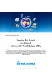
TRIGGER input and BLANK output are available at the rear of the instrument for synchronization with
other instruments.
1GP55_0E
TRIGGER
An external signal at this input triggers the LIST mode in operating modes
EXT-SINGLE and EXT-STEP. The polarity of the active trigger edge can be
set in the UTILITIES - AUX I/O - EXT TRIG SLOPE menu.
BLANK
This output supplies a signal (0 V/5 V) to blank the settling process by
means of pulse modulation or AM. The signal can also be used to
synchronize other instruments. The polarity of the signal can be set in the
UTILITIES - AUX I/O - BLANK POLARITY menu.
MARKER
At the first step of the LIST mode, this output provides an approx. 200 µs
trigger signal immediately after blanking. At small DWELL times, this signal
can be used for an accurate synchronization to trigger other devices and
shows the first stable output frequency. The delay to the fed-in signal at the
TRIGGER input for EXT-SINGLE or EXT-STEP is 1.5 to 2 ms and has a
jitter of 0.5 ms.
11
Rohde & Schwarz
Fast remote control of SMIQ
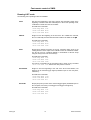
TRIGGER
Input
BLANK
Output
MARKER
Output
Frequency
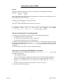
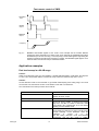
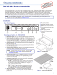
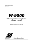
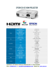
Fig. 3.1:
MARKER and BLANK signals in LIST mode. In this example the list contains different
frequencies and is operated in EXT STEP mode. Every signal at the TRIGGER input makes
the SMIQ step to the next list entry (= next frequency). The BLANK signal is high during the
frequency transitions until the target frequency is settled. The MARKER signal appears once
when the state of the first list entry is reached and stable.
Application examples
Fast level sweep in a 90 dB range
Problem:
Sweep a CW signal at 2 GHz once from 0 dBm to –90 dBm and backwards in 10 dB steps, the step time
is 3 ms. This is not possible with the normal level sweep, where the minimum step time is 10 ms.
Solution:
Set the attenuator mode to ELECTRONIC to get 90 dB noninterrupting level setting range. The levels
are stored in a list, then the list mode is run in SINGLE mode with 3 ms dwell time.
The commands for the entire procedure are as follows:
1GP55_0E
Command
Remarks
*RST;*CLS
Sets the instrument to a defined state. Note that *RST
switches off the RF output.
:SOUR:FREQ 2E9
Sets the carrier frequency to 2 GHz
:SOUR:POW 0
Sets the RF level to 0 dBm. To obtain a level setting
range from –90 dBm to 0 dBm in attenuator mode
ELECTRONIC, this command has to be sent before
switching to ELECTRONIC mode.
:OUTP:AMOD ELEC
Sets attenuator mode ELECTRONIC. This leads to
uninterrupted level settings in a range of 90 dB. It also
prevents switching of the attenuator when the
modulation
is
turned
on
or
off.
Note that setting attenuator mode ELECTRONIC
automatically sets the ALC mode to TABLE.
12
Rohde & Schwarz
Fast remote control of SMIQ
Therefore the next two commands are not necessary
in principle.
:SOUR:POW:ALC OFF
:SOUR:POW:ALC:SEAR OFF
Sets ALC mode TABLE.
uninterrupted level setting
:SOUR:POW:ALC:TABL?
:CAL:LATT?
To ensure highest level accuracy in attenuator mode
ELECTRONIC, these self-calibrating routines should
be called up at the beginning and after temperature
variations
of
more
than
5
degrees.
*WAI
Ensures that the next command is only executed after
the calibration is complete. Alternative: check status
with *OPC?
:SOUR:LIST:SEL 'LEVSWP'
Selects the list called LEVSWP. If there is no list of
this name, a new list is created.
:SOUR:LIST:FREQ 2GHz
Generates the frequency entries
:SOUR:LIST DWEL 3e-3
Sets the dwell time to 3 ms
:SOUR:LIST:POW 0dBm, -10dBm,
-20dBm, -30dBm, -40dBm,
-50dBm, -60dBm, -70dBm,
-80dBm, -90dBm, -80dBm,
-70dBm, -60dBm, -50dBm,
-40dBm, -30dBm, -20dBm,
-10dBm, 0dBm
Generates the level entries
:OUTP:STAT ON
The RF output has to be switched on before learning
the list. (*RST sets the output to OFF:)
:SOUR:LIST:LEAR
Determines the hardware setting of the entire list. This
command has to be sent after every change of the
list.
:SOUR:FREQ:MODE LIST
:SOUR:LIST:MODE AUTO
:TRIG:LIST:SOUR SING
Activates list mode in SINGLE mode. The instrument
now waits for a trigger command. Note that SMIQ sets
the frequency and level values of the last list entry in
this waiting state. The first list state is not set until a
trigger event is received.
:TRIG:LIST:IMM
Runs the list once.
:SOUR:FREQ:MODE CW
Switches off the list mode.
Note: Always leave list mode before changing other
hardware parameters.
Recommended
for
Frequency hopping with GSM/EDGE
Problem:
Generate a GSM frame with an EDGE burst in timeslot 0, all other time slots off. After transmission of
the burst, hop to a different frequency. For simplicity, we use only two frequencies here and only one RF
level (-10 dBm).
Solution:
Set the GSM frame in Digital Standard GSM/EDGE. Activate a hop trigger at the end of timeslot 0. Then
run the list mode in HOP mode.
Note: Options SMIQB11 and SMIQB20 are required for this example.
1GP55_0E
13
Rohde & Schwarz
Fast remote control of SMIQ
Command
Remarks
*RST;*CLS
Sets the instrument to a defined state. Note that *RST
switches off the RF output.
:SOUR:FREQ 890.2E6
Sets the carrier frequency to 890.2 MHz
:SOUR:POW –10dBm
Sets the RF level to -10 dBm.
:SOUR:GSM:SLOT0:TYPE EDGE
Timeslot 0 is set to an EDGE burst. Note that the
*RST value for timeslots 1 to 7 is off, so only timeslot
0 has to be configured here.
:SOUR:GSM:SLOT0:HOPP:TRIG ON
Activates the HOP trigger at the end of timeslot 0.
:SOUR:GSM:SEQ AAUT
Sets GSM to ARMED AUTO mode, i.e. the GSM
signal is not output until a trigger event is received.
The baseband generator is held at the first symbol of
the frame. This will produce a CW signal at the RF
output as soon as the RF is switched on.
Note: If your application requires that there is no
signal present before the list mode is started, you
should activate timeslot 1 instead of timeslot 0 in the
GSM frame. If you need the timeslot 0 parameters
(e.g. TSC), change the TSC in timeslot 1 (see SMIQ
user manual for details.)
:SOUR:GSM:STAT ON
Activates the GSM/EDGE system.
:SOUR:LIST:SEL 'GSMHOP'
Selects the list called LEVSWP. If there is no list of
this name, a new list is created.
:SOUR:LIST:FREQ 890.2MHz, 890.8MHz Generates two frequency entries with 600 kHz
spacing
1GP55_0E
:SOUR:LIST:POW -10dBm
Generates the level entry
:OUTP:STAT ON
The RF output has to be switched on before learning
the list. (*RST sets the output to OFF)
:SOUR:LIST:LEAR
Determines the hardware setting of the entire list. This
command has to be sent after every change of the
list.
:SOUR:FREQ:MODE LIST
:SOUR:LIST:MODE STEP
:TRIG:LIST:SOUR HOP
Activates list mode in HOP mode. The instrument now
waits for the hop trigger from the GSM/EDGE system.
Each trigger event causes a step to the next list entry.
Note that SMIQ sets the frequency and level values of
the last list entry in this waiting state. The first list
state is not set until a trigger event is received. This
will not happen until the GSM/EDGE system is
started.
:TRIG:DM:IMM
Starts the GSM/EDGE system.
:SOUR:FREQ:MODE CW
Switches off the list mode. Always leave the list mode
before changing other hardware parameters.
14
Rohde & Schwarz
Fast remote control of SMIQ
4 References
[1] Vector Signal Generator SMIQ, Operating Manual, PD 1125.5610.12, Rohde & Schwarz (2002)
[2] WCDMA Signal Generator Solutions by Rohde & Schwarz, Application Note 1GP39, Rohde &
Schwarz (2000)
[3] 3GPP Base Station Tests with Vector Signal Generator SMIQ, Application Note 1GP41, Rohde &
Schwarz (2001)
[4] Level Accuracy and Electronic Level Settings of SMIQ, Application Note 1GP42, Rohde & Schwarz
(2001)
5 Ordering information
Vector Signal Generator:
SMIQ02B
SMIQ03B
SMIQ04B
SMIQ06B
SMIQ03HD
SMIQ06ATE
300 kHz to 2.2 GHz
300 kHz to 3.3 GHz
300 kHz to 4.4 GHz
300 kHz to 6.4 GHz
300 kHz to 3.3 GHz
300 kHz to 6.4 GHz
1125.5555.02
1125.5555.03
1125.5555.04
1125.5555.06
1125.5555.33
1125.5555.26
Options:
SMIQB11
SMIQB12
SMIQB14
SMIQB15
SMIQB17
SMIQB20
SMIQB21
SMIQB42
SMIQB45
SMIQB47
SMIQB48
SMIQB49
SMIQB51
SMIQB60
Data Generator
Memory Extension
Fading Simulator
Second Fading Simulator for two channel or 12 path fading
Noise Generator and Distortion Simulator
Modulation Coder
BER Measurement
Digital Standard IS-95
Digital Standard WCDMA (3GPP)
Low ACP for CDMA and WCDMA
Extended Functions for WCDMA (3GPP)
Extended Fading Functions for WCDMA (3GPP)
Digital Standard GPS
Arbitrary Waveform Generator incl. WinIQSIM
1085.4502.04
1085.2800.04
1085.4002.02
1085.4402.02
1104.9000.02
1125.5190.02
1125.5490.02
1104.7936.02
1104.8232.02
1125.5090.02
1105.0587.02
1105.1083.02
1105.1831.02
1136.4390.02
TETRA T1 Simulator
1136.4290.02
Digital Standard IS-95 (option SMIQB60 required)
Digital Standard cdma2000 (option SMIQB60 required)
Digital Standard WCDMA Mode TDD (3GPP)
(option SMIQB60 required)
Digital Standard TD-SCDMA (option SMIQB60 required)
OFDM Signal Generation (option SMIQB60 required)
Digital Standard IEEE 802.11b (option SMIQB60 required)
Digital Standard 1xEV-DO (option SMIQB60 required)
Digital Standard IEEE 802.11a (option SMIQB60 required)
1105.0287.02
1105.0435.02
1105.1231.02
SMIQ-K8
WinIQSIM Options:
SMIQK11
SMIQK12
SMIQK13
SMIQK14
SMIQK15
SMIQK16
SMIQK17
SMIQK18
1105.1383.02
1105.1531.02
1154.7700.02
1154.7800.02
1154.7952.02
ROHDE & SCHWARZ GmbH & Co. KG . Mühldorfstraße 15 . D-81671 München . P.O.B 80 14 69 . D-81614 München .
Telephone +49 89 4129 -0 . Fax +49 89 4129 - 13777 . Internet: http://www.rohde-schwarz.com
This application note and the supplied programs may only be used subject to the conditions of use set forth in the
download area of the Rohde & Schwarz website.
1GP55_0E
15
Rohde & Schwarz