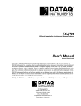
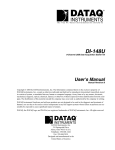
1
The way PC-based instrumentation should be
DI-5001
OEM Data Acquisition Board
User's Manual
Manual
Revision E
Copyright © 2008 by DATAQ Instruments, Inc. The Information contained herein is the exclusive property of
DATAQ Instruments, Inc., except as otherwise indicated and shall not be reproduced, transmitted, transcribed, stored
in a retrieval system, or translated into any human or computer language, in any form or by any means, electronic,
mechanical, magnetic, optical, chemical, manual, or otherwise without expressed written authorization from the company. The distribution of this material outside the company may occur only as authorized by the company in writing.
DATAQ Instruments' hardware and software products are not designed to be used in the diagnosis and treatment of
humans, nor are they to be used as critical components in any life-support systems whose failure to perform can reasonably be expected to cause significant injury to humans.
DATAQ, the DATAQ logo, and WINDAQ are registered trademarks of DATAQ Instruments, Inc. All rights reserved.
241 Springside Dr.
Akron, Ohio 44333 U.S.A.
Telephone: 330-668-1444
Fax: 330-666-5434
Designed and manufactured in the
United States of America
M-101029
Warranty and Service Policy
Product Warranty
DATAQ Instruments, Inc. warrants that this hardware will be free from defects in materials and workmanship under
normal use and service for a period of one year from the date of shipment. DATAQ Instruments' obligations under
this warranty shall not arise until the defective material is shipped freight prepaid to DATAQ Instruments. The only
responsibility of DATAQ Instruments under this warranty is to repair or replace, at its discretion and on a free of
charge basis, the defective material.
This warranty does not extend to products that have been repaired or altered by persons other than DATAQ Instruments employees, or products that have been subjected to misuse, neglect, improper installation, or accident.
DATAQ Instruments shall have no liability for incidental or consequential damages of any kind arising out of the sale,
installation, or use of its products.
Service Policy
1.
All products returned to DATAQ Instruments for service, regardless of warranty status, must be on a freight-prepaid basis.
2.
DATAQ Instruments will repair or replace any defective product within 5 days of its receipt.
3.
For in-warranty repairs, DATAQ Instruments will return repaired items to the buyer freight prepaid. Out of warranty repairs will be returned with freight prepaid and added to the service invoice.
DI–5001 OEM Board
Table of Contents
Warranty and Service Policy ................................................................................................................
1. Introduction ........................................................................................................................................
Features ..............................................................................................................................................
Analog Input ......................................................................................................................................
Analog Output ...................................................................................................................................
Digital Input and Output ....................................................................................................................
2. Specifications ......................................................................................................................................
Interface Characteristics ....................................................................................................................
Analog Inputs ....................................................................................................................................
Analog Outputs ..................................................................................................................................
Digital Input/Output ..........................................................................................................................
Timing Input/Output ..........................................................................................................................
Scan Lists ...........................................................................................................................................
Triggering ..........................................................................................................................................
On-board DSP ....................................................................................................................................
General ...............................................................................................................................................
Power Supply Voltage and Power Consumption ..............................................................................
3. Installation ..........................................................................................................................................
Applying Power via DIN Connector .................................................................................................
Printer Port Instrument Installation ...................................................................................................
USB Instrument Installation ..............................................................................................................
Ethernet Instrument Installation ........................................................................................................
Daisy-Chaining Multiple Ethernet Products ......................................................................................
TCP/IP Manager (Ethernet Models Only) ..................................................................................
WinDaq Waveform Navigator (Ethernet models only) ..............................................................
4. Connections and Pinouts ...................................................................................................................
DI-5001 Printer Port Board ...............................................................................................................
Printer Port Board Layout ...........................................................................................................
Printer Port Board Dimensions ...................................................................................................
Jumper Definitions ......................................................................................................................
Channels 1-16 Connector Pinout ................................................................................................
Channels 17-32 Connector Pinout ..............................................................................................
Power Jack Pinouts (Molex Connectors) ....................................................................................
DIN Power Connector Pinout .....................................................................................................
Connector Cross-Reference ........................................................................................................
DI-5001 Ethernet Board ....................................................................................................................
Ethernet Board Layout ................................................................................................................
Ethernet Board Jumper Definitions .............................................................................................
5. Calibration Verification .....................................................................................................................
Required Equipment ..........................................................................................................................
A/D Calibration ...........................................................................................................................
D/A Calibration ...........................................................................................................................
A/D Calibration Verification .............................................................................................................
D/A Calibration .................................................................................................................................
Offset Calibration Verification ..........................................................................................................
Table of Contents
v
iii
1
1
1
2
2
3
3
3
3
4
4
4
4
4
4
4
5
5
5
7
9
10
11
12
13
13
13
14
15
16
17
18
18
18
19
19
20
21
21
21
21
21
22
22
DI–5001 OEM Board
Full Scale (Span) Calibration Verification ........................................................................................
6. Block Diagram ....................................................................................................................................
DI-5001 Board ...................................................................................................................................
Ethernet Instruments ..........................................................................................................................
Table of Contents
vi
22
25
25
26
DI–5001 OEM Board
1. Introduction
The DI-5001 is a fully integrated OEM instrument that provides 32 single-ended or 16 differential analog input channels. It conveniently connects to the printer port of any desktop or portable PC and supports standard, bi-directional
and EPP modes and also supports USB and Ethernet interfaces like most DATAQ DI-7xx products. It features two
analog outputs with a range of ±10V, eight digital inputs, and eight digital outputs. Signal connections are made
directly to the two 40-pin headers.
There are two software approaches for the DI-5001: writing/developing your own acquisition, review and analysis
programs or using WINDAQ software. For the programmers who will be writing their own programs, we provide the
Programmer's Software Development Kit (SDK) free with every DI-5001. You will need to install the SDK to write
your own software. The SDK is installed when installing WINDAQ software (see “3. Installation” on page 5).
Non-programmers should use WINDAQ software (consisting of WINDAQ/Lite, WINDAQ/Pro, or WINDAQ/Pro+ acquisition software and WINDAQ Waveform Browser playback and analysis software). WINDAQ is easy-to-use, ready-torun, data recording, review and analysis software for the Windows™ environment. If you ordered WINDAQ/Pro or
WINDAQ/Pro+ recording software (an extra-cost option), there will be a sticker with a password on the sleeve of your
CD-ROM. This password will give you access to that software. WINDAQ/Lite recording software is available without
a password. WINDAQ/Lite recording software is limited to a maximum of 16 channels and 240 Hz maximum throughput when recording to disk. See “3. Installation” on page 5 to install WINDAQ software.
Features
The DI-5001 has the following features:
•
All instruments connect to the printer port of any PC-compatible computer. Most communicate in standard, bidirectional or EPP mode. Optional USB or Ethernet communications are available.
•
Per channel software-configurable settings including input gain, sample rate, intelligent oversampling modes
(signal averaging, maximum value, minimum value, and last point), and single-ended or differential input.
•
32 single-ended/16 differential (software selectable per channel) general purpose inputs.
•
Ethernet Instruments provide synchronous distributed data acquisition through CAT-5 Ethernet cables.
•
Flexible power requirements. All instruments operate from any standard 60Hz, 120V AC wall outlet with the
supplied power adapter. Alternately, you may power the instrument from any +9 to +36 volt DC source.
•
Can record at up to 200KHz throughput.
•
Analog-to-Digital converters. The DI-5001 provides 16-bit A/D converters for high-resolution measurement
accuracy (14 bits maximum resolution using WINDAQ software).
•
Supports analog pre- and post-triggering of data acquisition based on the level and slope of a specified channel.
Analog Input
32 single-ended/16 differential analog inputs allow your analog signals to be converted into 14-to-16-bit digital data
via the on board A/D converter. The DI-5001 features jumper-selectable input ranges of ±10 volts full scale or ±5
volts full scale. Input measurement ranges are as follows:
±10 volts full-scale
±5 volts full scale
±10V at a gain of 1
±5V at a gain of 2
±2.5V at a gain of 4
±1.25V at a gain of 8
±5V at a gain of 1
±2.5V at a gain of 2
±1.25V at a gain of 4
±0.625V at a gain of 8
Introduction
1
DI–5001 OEM Board
Analog Output
The D/A subsystem features two buffered, 12-bit D/A converters for outputting analog data. DI-5001 instruments
feature a software-programmable output range of ±10V and feature an on-board 16-entry output counter list that
allows you to write analog or digital output at the maximum conversion rate of the instrument.
Note: Analog output is not available in Ethernet and USB modules while Analog Input is being used.
Digital Input and Output
The Printer Port version of the DI-5001 contains 8 digital input and 8 digital output lines for input/output operations.
These lines provide an interface for the transfer of data between user memory and a peripheral device connected to
the instrument. Digital inputs can monitor alarms or sensors with TTL outputs, while digital outputs can drive TTL
inputs on control or measurement equipment. The Ethernet and USB versions have 8 digital input and 4 digital output
lines available.
Introduction
2
DI–5001 OEM Board
2. Specifications
Interface Characteristics
Compatible computer architecture:
Any PC architecture. Connects to computer via the parallel (or printer)
port. Supports standard, bi-directional, or EPP communication modes
(Ethernet and USB models only support bi-directional and EPP communication modes). Optional communication interfaces include Ethernet
and Universal Serial Bus (USB).
Analog Inputs
Number of input channels:
32 single-ended, 16 differential (software selectable per channel)
Converter resolution:
16-bit
Common mode rejection ratio:
80 dB minimum @ Av=1
Accuracy:
±0.25% of full-scale range ±100µv @ 25ºC ±5ºC, ±100ppm/ºC
Crosstalk:
-75 dB @ 100kHz and 100 unbalance
Sample throughput rate (max samples/second; software selectable per channel):
Printer port: Standard port: 40,000; Bi-directional port: 80,000; EPP: 200,000
USB 200,000 samples/second max
Ethernet 180,000 samples/second max
Maximum analog measurement range (software selectable per channel):
±10 Volts Full Scale: ±10V full scale at a gain of 1
±5V full scale at a gain of 2
±2.5V full scale at a gain of 4
±1.25V full scale at a gain of 8
±5 Volts Full Scale: ±5V full scale at a gain of 1
±2.5V full scale at a gain of 2
±1.25V full scale at a gain of 4
±0.625V full scale at a gain of 8
Maximum Input without Damage:
±30VDC or Peak AC (either input to ground)
Gain error:
1 bit max @ 1kHz sample rate
Input offset voltage:
1 bit max @ 1kHz sample rate
Input settling time:
4µs to 0.01% at all gains
Input impedance:
1 MΩ resistor tied to GND on the input channel
Analog Outputs
Number of channels:
Two buffered analog outputs
Resolution:
12-bit; 1 part in 4,096
Output voltage range:
±10V full scale
Output impedance:
0.1Ω - output current should not exceed 1mA (10KΩ load or lighter)
Output offset voltage:
1 bit max @ 1kHz sample rate
Specifications
3
DI–5001 OEM Board
Digital Input/Output
Capacity:
8 input and 8 output
Compatibility:
TTL compatible
Max source current:
0.4mA @ 2.4V
Max sink current:
8mA @ 0.5V
Digital input termination:
4.7kΩ pull-up to +5VDC
Timing Input/Output
Resolution:
1 part in 32,768
Base clock accuracy:
0.01%
Counter input frequency:
16 MHz
Scan Lists
Input Scan List:
Capacity—240 elements
Output Scan List:
Capacity—16 elements
Triggering
Pre-trigger length:
64K samples
Post-trigger length:
64K samples
Trigger channel:
Any channel
Trigger level hysteresis:
8-bit (256 counts)
On-board DSP
Type:
Analog Devices ADSP2181, 32 MIPS
Clock frequency:
16 MHz external, 64 MHz internal
Data memory:
8k words
Program memory:
8k words
General
Operating environment:
Component temperature
-40º to 70º C
Relative humidity
0% to 90% non-condensing
Storage Temperature:
-40º to 100º C
Storage Relative Humidity:
0% to 90% non-condensing
Power Supply Voltage and Power Consumption
Voltage:
9-36 VDC
Power:
4.5 Watts + Ethernet or USB module
Specifications
4
DI–5001 OEM Board
3. Installation
Applying Power via DIN Connector
Use the following procedure to apply power to your DI-5001 OEM board:
1.
Plug the five-pin DIN end of the power adapter cable into the five-pin jack on the back of the DI-5001 board (see
“DI-5001 Printer Port Board” on page 13).
2.
Plug the appropriate end of the supplied power cord into the power adapter and the other end into any standard
120VAC, 60Hz, single-phase outlet. If an alternate power source is to be used, refer to the following pin-out diagram for power requirements:
+9 to +36 V
3.
Common
Turn the POWER switch on.
Printer Port Instrument Installation
All DI-5001instruments can use your computer's parallel (or printer) port to interface digital and analog signals to
your computer. Ethernet/USB models provide Ethernet or USB communication ports (cannot be used concurrently
with the printer port).
1.
Plug the appropriate end of the supplied parallel communications cable to the 25-pin male connector on the back
end of the DI-5001 board (see “DI-5001 Printer Port Board” on page 13).
2.
Connect the other end of this cable to your computer's parallel (printer) port. Note the LPT port number to which
you connected your device (LPT1, LPT2, etc.).
3.
Set up your computer’s Printer Port operating mode. The parallel port may be set up in Standard, Bi-directional,
or EPP mode to communicate with your instrument. Choose a parallel port mode based on the desired sample
rate:
Parallel Port Mode
Maximum Data Throughput*
Standard
40,000 samples/second
Bi-directional (PS/2)
80,000 samples/second
EPP
200,000 samples/second
*Maximum stream-to-disk rate using WINDAQ software on a 350 MHz Pentium II machine
running Windows 98. Triggered storage rates will be faster. Contact DATAQ Instruments to
determine expected maximum sample rates for other machine speeds and operating systems.
For example, if you will record five channels at 20 Hz each, then the Standard mode will be more than adequate
(5 channels @ 20 Hz = 100 Hz throughput, which is well within the DI-7xx Series 40KHz standard mode
throughput). If, however, you plan to record at a much higher sample rate (for example, five channels at 10KHz
each) the Standard mode will not reliably record your data gap-free — this throughput rate exceeds the DI-7xx's
standard mode maximum throughput (5 channels @ 10KHz = 50KHz). To reliably record data gap-free at this
sample rate, your computer's parallel port must be operated in something other than standard mode.
Access your computer's CMOS setup routine to change the printer port operating mode. This usually can be
accomplished by pressing a certain key (or keys) on your keyboard at the beginning of your computer's boot-up
process. A message telling you which key to press is usually displayed on your monitor at the beginning of the
Installation
5
DI–5001 OEM Board
boot-up process. If you do not see such a message, consult your computer documentation for CMOS setup information.
4.
Apply power to the DI-5001 board. Windows must be running. Close all other applications.
5.
Install WINDAQ Software. All software is included in The WINDAQ Resource CD.
a.
Insert the The WINDAQ Resource CD into your CD-ROM drive. The Windows auto run feature should start
the installation program. If the Windows auto run feature is not enabled on your PC, run the setup.exe program located on the root of the CD directory.
b.
In the “What do you want to do?” dialog box select the Install Software radio button and click OK.
c.
In the “Installing Software” dialog box select the Install Software for all other products radio button and
click OK.
d.
In the “Specify the product” dialog box you must choose the version of WINDAQ you would like to install. If
you purchased WINDAQ/Pro or Pro+ software, select the appropriate option and click OK. If you did not
purchase software, choose the WINDAQ/Lite option and click OK.
e.
In the “Specify the Instrument” dialog box select the DI-720/740/730HV Portable Instruments radio button and click OK.
f.
In the “Specify the Instrument” dialog box select the Parallel Port (Printer Port) radio button and click
OK.
g.
Read the warning information and follow any instructions relevant to your situation in the “Welcome” dialog box. Click OK to continue the installation.
h.
Read through the Software License agreement carefully and either Accept and Continue or Cancel to exit
the installation.
i.
Enter your Registration Information in the appropriate text boxes and click OK.
j.
Select the destination directory where you would like all folders and files to reside on your hard drive. We
recommend you accept the default path, but you can name this new directory anything you like. Simply substitute the desired drive and directory in the Destination Directory text box. Once you have chosen the directory click OK.
k.
The “Make Backups?” dialog box provides the option of creating backup copies of any files that may be
replaced during installation. This is a safety courtesy; backup copies are not required. Click on No if you
don't want to make backups. Click on Yes to create backups. If you decide to create backups, you will be
prompted to specify a backup file directory.
l.
Specify the instrument you are installing. Select the DI-720/DI-740/DI-722/DI-5001 Portable Unit radio
button. Click OK to continue.
m. Choose the Printer Port you connected your instrument to (LPT1, LTP2, or LPT3). Click OK to continue.
n.
Select the program manager group you would like to place the program shortcuts in your Windows programs. The default is recommended, but you can specify any program group or create a new one. Click OK
to continue.
o.
The “Installation Option” dialog box allows you to specify access to WINDAQ for multiple users on the same
PC. If you are the only user or you would like to allow access to all users click Yes. If there are multiple
users and you would like to be the only one able to access WINDAQ click No. Click Cancel to abort the
installation.
Installation
6
DI–5001 OEM Board
6.
p.
Select the desired options for installation of WINDAQ/XL and Advanced CODAS.
q.
Installation is complete. Re-start your PC to enable WINDAQ device drivers for the printer port.
Run WinDaq software from the program group designated in Step 5n above (default is Start > Programs >
WINDAQ > WinDaq Pro(version of the software installed - Lite/Pro/Pro+) Data Acq DI-7xx(model number)
LPT. For help running WinDaq Acquisition and Playback software please see the help files inside the application
(F1 for context-sensitive help or use the Help menu).
USB Instrument Installation
USB instruments require driver installation before they can communicate with your PC. Your USB device may be
installed and run as a Printer Port device if desired (see “Printer Port Instrument Installation” on page 5 to install and
run as a Printer Port device). The USB and Printer Port communications interfaces cannot be used concurrently.
1.
Apply power to the DI-5001 board and your computer. Windows must be running. Close all other applications.
2.
Plug the appropriate end of the supplied USB communications cable into the USB port on the back of the board.
Connect the other end of this cable to your computer's USB port.
3.
The addition of this new hardware will be “sensed” by Windows and the “Add New Hardware Wizard” will automatically be launched, anticipating the installation of a device driver for the new hardware. Insert the WINDAQ
Resource CD-ROM into your CD-ROM drive. The root directory of the CD contains all USB drivers.
4.
From the initial “Add New Hardware Wizard” screen click Next to get started, then choose the “search for best
driver option (recommended)” and click Next.
5.
Specify the CD-ROM drive that contains the WINDAQ Resource CD-ROM as the search location and click Next.
6.
Follow the on-screen prompts. Depending on how Windows was originally installed on your computer, you may
need additional files from your Windows distribution CD-ROM to complete the driver installation. When you
see the following dialog box, Windows has located the necessary device driver and is ready to install the required
files. Click Next to continue.
7.
Install WINDAQ Software. All software is included in The WINDAQ Resource CD.
a.
Insert the The WINDAQ Resource CD into your CD-ROM drive. The Windows auto run feature should start
the installation program. If the Windows auto run feature is not enabled on your PC, run the setup.exe program located on the root of the CD directory.
Installation
7
DI–5001 OEM Board
b.
In the “What do you want to do?” dialog box select the Install Software radio button and click OK.
c.
In the “Installing Software” dialog box select the Install Software for all other products radio button and
click OK.
d.
In the “Specify the product” dialog box you must choose the version of WINDAQ you would like to install. If
you purchased WINDAQ/Pro or Pro+ software, select the appropriate option and click OK. If you did not
purchase software, choose the WINDAQ/Lite option and click OK.
e.
In the “Specify the Instrument” dialog box select the DI-720/740/730HV Portable Instruments radio button and click OK.
f.
In the “Specify the Instrument” dialog box select the Universal Serial Bus (USB) radio button and click
OK.
g.
The “Welcome!” dialog box allows you to cancel the installation. Click OK to continue installation or Cancel to abort.
h.
Read through the Software License agreement carefully and either Accept and Continue or Cancel to exit
the installation.
i.
Enter your Registration Information in the appropriate text boxes and click OK.
j.
Select the destination directory where you would like all folders and files to reside on your hard drive. We
recommend you accept the default path, but you can name this new directory anything you like. Simply substitute the desired drive and directory in the Destination Directory text box. Once you have chosen the directory click OK.
k.
The “Make Backups?” dialog box provides the option of creating backup copies of any files that may be
replaced during installation. This is a safety courtesy; backup copies are not required. Click on No if you
don't want to make backups. Click on Yes to create backups. If you decide to create backups, you will be
prompted to specify a backup file directory.
l.
Select the program manager group you would like to place the program shortcuts in your Windows programs. The default is recommended, but you can specify any program group or create a new one. Click OK
to continue.
m. Enter the ID address of your instrument. Every DI-5001 USB board is initially assigned an ID address of 0.
If you are adding only one DI-5001 to your system or if this is the first USB instrument you are installing, do
not change the ID address. If this is not the first device, change the ID address. The second device installed
should have an ID address of 1, the third device installed should have an ID address of 2, etc. Click OK to
continue installation.
8.
n.
The “Installation Option” dialog box allows you to specify access to WINDAQ for multiple users on the same
PC. If you are the only user or you would like to allow access to all users click Yes. If there are multiple
users and you would like to be the only one able to access WINDAQ click No. Click Cancel to abort the
installation.
o.
Select the desired options for installation of WINDAQ/XL and Advanced CODAS.
p.
Installation is complete. If you are installing multiple devices, run through the installation for each device
making sure to change the ID address in step m above. This does not install multiple versions of the software.
Run WinDaq software from the program group designated in Step 7n above (default is Start > Programs >
WINDAQ > WinDaq Pro(version of the software installed - Lite/Pro/Pro+) Data Acq DI-7xx(model number)
Installation
8
DI–5001 OEM Board
USBx(ID address - usually 0). For help running WinDaq Acquisition and Playback software please see the help
files inside the application (F1 for context-sensitive help or use the Help menu).
Ethernet Instrument Installation
Your Ethernet device may be installed and run as a Printer Port device if desired (see “Printer Port Instrument Installation” on page 5 to install and run as a Printer Port device). The Ethernet and Printer Port communications interfaces
cannot be used concurrently. If you are installing multiple devices in a daisy chain for the purpose of synchronous
distributed data acquisition please see “Daisy-Chaining Multiple Ethernet Products” on page 10 before installing the
software. You may only access one device per network outside your subnet.
1.
Connect one end of a CAT-5 Ethernet cable to the Toward PC port on the back end of the board (see “DI-5001
Ethernet Board” on page 19).
2.
Connect the other end of the CAT-5 Ethernet cable to an Ethernet port on your PC or to a port on an accessible
network.
Note: DO NOT connect the Expansion port back to your network or PC. These Ethernet products use an Ethernet
switch. Looping any Ethernet switch will cause your network or PC to crash.
3.
Apply power to the DI-5001 board and your computer. Windows must be running. Close all other applications.
4.
Install WINDAQ Software. All software is included in The WINDAQ Resource CD.
a.
Insert the The WINDAQ Resource CD into your CD-ROM drive. The Windows auto run feature should start
the installation program. If the Windows auto run feature is not enabled on your PC, run the setup.exe program located on the root of the CD directory.
b.
In the “What do you want to do?” dialog box select the Install Software radio button and click OK.
c.
In the “Installing Software” dialog box select the Install Software for all other products radio button and
click OK.
d.
In the “Specify the product” dialog box you must choose the version of WINDAQ you would like to install. If
you purchased WINDAQ/Pro or Pro+ software, select the appropriate option and click OK. If you did not
purchase software, choose the WINDAQ/Lite option and click OK.
e.
In the “Specify the Instrument” dialog box select the DI-720/740/730HV Portable Instruments radio button and click OK.
f.
In the “Specify the Instrument” dialog box select the Ethernet radio button and click OK.
g.
Check the sticker located on the bottom of your instrument and note the model number. In the “Select a
device” dialog select the model number of your device and click OK.
h.
The “Welcome!” dialog box allows you to cancel the installation. Click OK to continue installation or Cancel to abort.
i.
Read through the Software License agreement carefully and either Accept and Continue or Cancel to exit
the installation.
j.
Enter your Registration Information in the appropriate text boxes and click OK.
k.
Select the destination directory where you would like all folders and files to reside on your hard drive. We
recommend you accept the default path, but you can name this new directory anything you like. Simply substitute the desired drive and directory in the Destination Directory text box. Once you have chosen the directory click OK.
Installation
9
DI–5001 OEM Board
l.
The “Make Backups?” dialog box provides the option of creating backup copies of any files that may be
replaced during installation. This is a safety courtesy; backup copies are not required. Click on No if you
don't want to make backups. Click on Yes to create backups. If you decide to create backups, you will be
prompted to specify a backup file directory.
m. Select the program manager group you would like to place the program shortcuts in your Windows programs. The default is recommended, but you can specify any program group or create a new one. Click OK
to continue.
5.
n.
You must know either the MAC address or the IP address of the device to continue. The MAC address is
located on the sticker on the bottom of your device. IP addresses must be retrieved from the system administrator. Enter the MAC address or IP address in the text box provided in the “MAC or IP address of the
device” dialog box. If you are installing a device that is not connected to your Local Area Network, you
should enter the IP address here. The software will go to that IP address and retrieve the MAC address for
you. This will save further setup in the TCP/IP Manager. Click OK to continue. Note: If you enter the wrong
MAC address you will have to re-run this installation program with the correct MAC address to access the
device.
o.
Click Yes in the “More ethernet devices to install” dialog box if you are installing multiple Ethernet devices.
p.
Repeat Steps m and n until all Ethernet devices’ MAC addresses have been entered. Click No to continue
installation.
q.
The “Installation Option” dialog box allows you to specify access to WINDAQ for multiple users on the same
PC. If you are the only user or you would like to allow access to all users click Yes. If there are multiple
users and you would like to be the only one able to access WINDAQ click No. Click Cancel to abort the
installation.
r.
Select the desired options for installation of WINDAQ/XL and Advanced CODAS.
s.
Installation is complete.
Run the TCP/IP Manager via the Windows program group specified during WINDAQ Software installation (step
4m above — default is Start > Programs > WINDAQ > IP Manager) to access the device and run WINDAQ
Acquisition Software.
Daisy-Chaining Multiple Ethernet Products
Multiple Ethernet boards may be daisy-chained together to allow for one synchronous distributed data acquisition
system. Multiple DI-5001 boards, as well as DI-720, DI-722, and/or DI-730 instruments may be placed in the same
daisy chain. To maintain synchronicity, Ethernet hubs and switches cannot be used between units. Make sure to enter
each MAC address during installation. Daisy-chains must be installed to your Local Area Network (LAN) — you
cannot access more than one device per IP address outside of your subnet. If you are not sure whether or not the
devices are in your subnet see your system administrator before installation. You may acquire data from only one
daisy chain at a time (i.e., the same PC cannot access two daisy chained groups at the same time).
Note: If you are installing a daisy-chained group of instruments for the purpose of synchronous distributed data
acquisition, do not allow any other units or daisy chains to be installed to your subnet. Running other devices on the
same subnet will cause the synced units to become unsynced.
1.
Connect one end of a CAT-5 Ethernet cable to the Toward PC port (see “DI-5001 Ethernet Board” on page 19)
of the first Ethernet device.
2.
Connect the other end of the same CAT-5 Ethernet cable to the Ethernet port on your PC or LAN.
Installation
10
DI–5001 OEM Board
3.
Connect one end of another CAT-5 Ethernet Cable to the Expansion port (see “DI-5001 Ethernet Board” on
page 19) on the rear of the first Ethernet device.
4.
Connect the other end of the same CAT-5 Ethernet cable to the Toward PC port (see “DI-5001 Ethernet Board”
on page 19) on the second Ethernet device.
5.
Continue installing more Ethernet devices by connecting a CAT-5 Ethernet cable to the Expansion port of the
last device in the chain and the Toward PC port on the next device you are adding to the chain. Up to 32 devices
may be installed in a single daisy chain. Each device may be 100 meters apart.
Note: DO NOT connect the Expansion port on the last product in the chain back to your network or PC. These Ethernet products use an Ethernet switch. Looping any Ethernet switch will cause your network or PC to crash.
Use the TCP/IP Manager to run WINDAQ Acquisition Software (see “TCP/IP Manager (Ethernet Models Only)” on
page 11). WINDAQ Acquisition Software provides data acquisition and recording capabilities. Daisy-chained units
record separate files synchronously (one file for each unit) and place them in a user-defined Session folder. The user
may define which units to use in a daisy-chain so not all units have to be used for a recording session.
Use the WWB Navigator to playback and analyze multiple data files in a Session folder (see “WinDaq Waveform
Navigator (Ethernet models only)” on page 12) synchronously. The user may choose which files to view and analyze
so not all data files in a session have to be viewed at the same time. Individual files may be independently opened
using WINDAQ Playback Software (WINDAQ Waveform Browser).
TCP/IP Manager (Ethernet Models Only)
The TCP/IP Manager allows you to easily manage all DI-5001, DI-720, DI-722 and DI-730 Ethernet Instruments
installed on your PC. The TCP/IP manager is installed when installing WINDAQ Software. Access the TCP/IP Manager via the Windows program group specified during WINDAQ Software installation (default is Start > Programs >
WINDAQ > IP Manager). For help with TCP/IP settings and the TCP/IP Manager see the help files accessible in the
application (press F1 to access context-sensitive help or use the Help menu).
The main TCP/IP window shows all Ethernet devices installed on your PC. Devices could be busy or unavailable if
there are multiple users. If you entered the wrong MAC address during installation, the status of the device will be
“Off Line.” “UnSynced” devices are all single units installed to your network (units that are not daisy-chained).
Synced Groups are daisy-chained instruments. There is one Synced Group for each daisy chain. Each Synced Group
is named using the first device in the chain (in parentheses).
Use the drop down command menu to change the description of a device. All commands are performed by first
selecting a device, then using the drop down command menu. Multiple devices in the same Synced Group may be
Installation
11
DI–5001 OEM Board
selected for a recording session by using the Shift or Control key. Multiple Synced Groups cannot be accessed by the
same PC at the same time.
Note: DI-5001 boards will show in the TCP/IP Manager as a DI-720.
WINDAQ Acquisition software must be initiated from the TCP/IP Manager for all Ethernet instruments. To begin a
recording session select a single device or a group of daisy-chained devices (using the Control or Shift key) and click
the Start WINDAQ button. Each device will open an instance of WINDAQ Acquisition software. Change channel settings, calibration, and display options independently for each device using each instance of WINDAQ. Most WINDAQ
menu items are available when recording synced devices with the following exceptions: The Open and Record menu
items in the File Menu are not available; The Triggered Mode, Triggered Storage, and Remote Storage menu items in
the Options Menu are not available.
WINDAQ Waveform Navigator (Ethernet models only)
The WINDAQ Waveform Browser Navigator allows you to display and scroll through data recorded synchronously
using multiple daisy-chained DI-5001, DI-720, DI-722, and/or DI-730 Ethernet instruments.Access the application
via the Windows program group specified during WINDAQ Software installation (default is Start > Programs >
WINDAQ > WWB Navigator). Select multiple files from a Session folder to open them in the WINDAQ Waveform
Navigator. Use the scroll bar to navigate through all the data files synchronously.
For help with the WINDAQ Waveform Navigator see the help files accessible in the application (press F1 to access
context-sensitive help or use the Help menu).
Installation
12
DI–5001 OEM Board
4. Connections and Pinouts
DI-5001 Printer Port Board
Printer Port Board Layout
PGA
Offset
Channels 17-32
Channels 1-16
Gain
Offset
DAC1
+5
VDC
DAC2
+9-36
VDC
DSP
PLD
Parallel Port
Connector
Power
LED
Active
LED
Power Connector
(DIN connector)
Connections and Pinouts
13
Power
Switch
DI–5001 OEM Board
Printer Port Board Dimensions
Channels 17-32
PGA
Offset
Channels 1-16
O
Offset
DAC1
+5
VDC
DAC2
+9-36
VDC
DSP
PLD
Parallel Port
Connector
Power
LED
Active
LED
Power Connector
(DIN connector)
Connections and Pinouts
14
Power
Switch
DI–5001 OEM Board
Jumper Definitions
For location of jumpers please see “DI-5001 Printer Port Board” on page 13.
Jumper Description
JP3 ON = +5V appears in pin 1 on Channel 17-32 connector (default).
OFF = No +5V on Channel 17-32 connector.
JP4 ON = Allow DAC1 output (default).
OFF = Disallow DAC1 output.
JP5 ON = +5V appears in pin 1 of Channel 1-16 connector (default).
OFF = No +5V on Channel 1-16 connector.
J5 DOUT 1-3 enable: ON is default for EN and P, OFF is default for USB
1-2: ON = DO1 enabled; OFF = DO1disabled
3-4: ON = DO2 enabled; OFF = DO2 disabled
5-6: ON = DO3 enabled; OFF = DO3 disabled
JP6 ON = Allow DAC2 output (default).
OFF = Disallow DAC2 output.
JP7 Designated for manufacturer use.*
JP8 Designated for manufacturer use.*
JP9 Designated for manufacturer use.*
JP12 Designated for manufacturer use.*
JP13 LED output, only when PCB-mount LED D1 and D2 are NOT installed:
1 = Red LED control (cathode)
2 = Red LED anode
3 = Green LED anode
4 = Ground Green LED cathode
JP14 Designated for manufacturer use.*
JP15 Designated for manufacturer use.*
JP19 Designated for manufacturer use.*
JP20 Pseudo-differential
and 1-2 & 3-4 = Standard analog ground (default).
JP21 2-3 = AGND (pin 18 on 37 pin D connector) will become pseudo-differential ground for all channels.
JP22 DAC selection
1-2: DAC2 appears in Channel 1-16 connector
2-3: DAC1 appears in Channel 1-16 connector
JP23 DAC selection
1-2: DAC2 appears in Channel 17-32 connector
2-3: DAC1 appears in Channel 17-32 connector
JP24 Designated for manufacturer use.*
* Do not change ANY jumper designated for manufacturer use. Doing so may void your warranty.
Connections and Pinouts
15
DI–5001 OEM Board
Channels 1-16 Connector Pinout
Allows you to connect analog input channels 1 through 16, eight digital inputs, and eight digital outputs to the DI5001. Other connections include DAC2, which is a digital-to-analog converter that serves as a general-purpose analog output, and two analog grounds. Pinout is as follows:
Pin #
1
2
3
4
5
6
7
8
9
10
11
12
13
14
15
16
17
18
19
20
21
22
23
24
25
26
27
28
29
30
31
32
33
34
35
36
37
38-40
Function
+5V power
Digital in 4
Digital in 5
Digital in 6
Digital out 3
Digital out 2
Digital out 1
Digital out 0
Digital in 3
Digital in 2
Digital in 1
Digital in 0
Power ground
Digital out 4
Digital out 6
Digital out 7
DAC2
Analog ground
Digital out 5
Digital in 7
Channel 16
Channel 8
Channel 15
Channel 7
Channel 14
Channel 6
Channel 13
Channel 5
Channel 12
Channel 4
Channel 11
Channel 3
Channel 10
Channel 2
Channel 9
Channel 1
Analog ground
Reserved
Connections and Pinouts
16
DI–5001 OEM Board
Channels 17-32 Connector Pinout
Allows you to connect analog input channels 17 through 32. This connector also includes DAC1, which is a second
digital-to-analog converter that serves as a general purpose analog output; R. START/STOP, which allows you to
remotely start and stop data storage to disk with a switch or TTL level signal; EVNT, which allows you to remotely
trigger event markers with a switch or TTL level signal; and two analog grounds. Pinout is as follows:
Pin #
1
2
3
4
5
6
7
8
9
10
11
12
13
14
15
16
17
18
19
20
21
22
23
24
25
26
27
28
29
30
31
32
33
34
35
36
37
38-40
Function
+5V power
Reserved
Reserved
Reserved
Reserved
Reserved
Reserved
Reserved
Reserved
Reserved
Remote start/stop
Remote event marks
Power Ground
Reserved
Reserved
Reserved
DAC1
Analog ground
Reserved
Reserved
Channel 32
Channel 24
Channel 31
Channel 23
Channel 30
Channel 22
Channel 29
Channel 21
Channel 28
Channel 20
Channel 27
Channel 19
Channel 26
Channel 18
Channel 25
Channel 17
Analog Ground
Reserved
Connections and Pinouts
17
DI–5001 OEM Board
Power Jack Pinouts (Molex Connectors)
+5
VDC
(J1)
+9-36
VDC
(J2)
+5V
N/C
Common
Common
N/C
+
+5V Power Jack (J1)—Allows a +5VDC source to power the instrument. Cannot be used with USB or Ethernet
boards.
+9-36V Power Jack (J2)—Allows any suitable (+9 to +36VDC @ 3A) alternate source to power the instrument.
DIN Power Connector Pinout
+9 to +36 V
Common
Allows you to connect DATAQ’s power adapter.
Connector Cross-Reference
Mating connector cross reference to commercial and DATAQ Instruments part numbers:
Location and Description
DATAQ Part Number
Commercial Part Number
JP1 and JP2
40-pin channel connectors
Channels 1-16 and Channels 17-32
100342-40
3M# 89140-0101
J1 and J2
4-Pin Power Jacks (Molex Connectors)
+5VDC and +9-36 VDC
100462-1
Digi-Key# A14384-ND
J3
Parallel Printer Port Connector (standard)
100342-26
3M# 89126-0101
100464
AESCO# 05BLMX
J4
DIN Power Connector
Connections and Pinouts
18
DI–5001 OEM Board
DI-5001 Ethernet Board
The Ethernet interface option adds an Ethernet daughter board mounted on top of the standard printer port board. All
of the interconnections on the printer port board (see “Printer Port Board Layout” on page 13) are available on the
Ethernet DI-5001. Please be sure to read ALL material for the printer port board for proper interconnections.
Ethernet Board Layout
PGA
Offset
Channels 17-32
Channels 1-16
Gain
O
Offset
DAC1
+5
VDC
V
DAC2
+9-36
VDC
DSP
PLD
Parallel Port
Connector
Toward PC
Ethernet Port
Expansion
Ethernet Port
Green “Link”
LEDs
The Ethernet Ports both use standard CAT-5 Ethernet Cables.
Connections and Pinouts
19
DI–5001 OEM Board
Ethernet Board Jumper Definitions
For location of jumpers please see “DI-5001 Ethernet Board” on page 19.
Jumper Description
JP10 Designated for manufacturer use.*
JP14 1-2: OFF = 14-bit resolution (default); ON = 16-bit resolution. Note: WinDaq does not support 16-bit resolution.
11-12: ON = Forbid remote modification; OFF = Allow remote modification (default). Remote modification allows you to change the static IP of a device.
All other pins are designated for manufacturer use.*
* Do not change ANY jumper designated for manufacturer use. Doing so may void your warranty.
Connections and Pinouts
20
DI–5001 OEM Board
5. Calibration Verification
This section provides calibration verification procedures for the A/D and D/A subsystems of the DI-5001 board. Your
instrument is calibrated before it is shipped and, therefore, does not need immediate calibration. Should your unit not
comply with the calibration guidelines presented below, arrange to have DATAQ Instruments recalibrate your instrument.
Required Equipment
A/D Calibration
•
A precision DVM with resolution as a function of the input range being calibrated:
minimum DVM resolution = Instrument FSR x 0.1%
For example, suppose we have the DI-5001 Printer Port board and we want to calibrate the ±10 volt range (the
DI-5001 delivers ±10 volts at a gain of 1):
10V x 0.1% = 10mV
So we would need a DVM with a resolution of 10V or more to calibrate the ±10 volt range.
•
A stable voltage source with a stability specification equal to or greater than the minimum DVM resolution, as
calculated above, required to calibrate the instrument at the highest desired gain.
OR
•
An alternative is to use a voltage calibrator with enough resolution, as calculated above, to calibrate the instrument at the highest desired gain.
D/A Calibration
•
A precision DVM with resolution of at least 1mV.
A/D Calibration Verification
Calibration verification of the DI-5001 board A/D subsystem is performed on channel 1, with all other channels
returned to analog common. The following figures illustrate the necessary connections:
DVM
Voltage
Source
+
-
CH1
CH2
CH3
CH4
CH5
CH6
CH7
CH8
CH9
+
CH30
CH31
CH32
S.GND
(signal ground)
Calibration Verification
21
DI–5001 OEM Board
Or if you are using the alternative voltage calibrator, the following figure illustrates the necessary connections:
+
Voltage
Calibrator -
CH1
CH2
CH3
CH4
CH5
CH6
CH7
CH8
CH9
CH30
CH31
CH32
S.GND
(signal ground)
D/A Calibration
D/A calibration involves adjusting the analog outputs to the correct full-scale range using the analog data value. The
following figure illustrates the necessary connections:
'$&'$&
6*1'
VLJQDOJURXQG
'90
When the above circuit is connected, the calibration program can be initiated by typing “DI720CAL” at the DOS
prompt. D/A calibration is accomplished by following the on screen prompts.
Offset Calibration Verification
1.
Connect your voltage calibrator, or combination DVM and voltage source to your DI-5001 instrument as shown
above. Apply zero volts to the instrument (or short the instrument's analog channel input to ground).
2.
Open the WINDAQ/Lite/Pro/Pro+ data acquisition screen. Enable the channel you will use to quantify offset.
Since all channels are adjusted together, any channel may be selected. Enable a maximum burst sample rate of
50,000 Hz by selecting EDIT-PREFERENCES-MAX SAMPLE RATE. Enable a WINDAQ sample rate of 50 Hz.
Set the Acquisition Mode to AVERAGE and the gain factor to 1 through WINDAQ’s CHANNEL SETTINGS
menu for the selected channel.
3.
Referring to WINDAQ software's voltage display for the channel you're evaluating, compare this value to that
given in the OFFSET column of TABLE (1) for the selected gain factor.
4.
Repeat steps 2 and 3 using a gain of 2, 4 and 8 for the selected channel.
5.
If any readings are out of the acceptable ranges described in TABLE (1) arrange to have your instrument recalibrated by DATAQ Instruments.
Full Scale (Span) Calibration Verification
6.
Referring again to TABLE (1) set the instrument's gain to 1 and apply the voltage indicated by the SPAN VOLTAGE column of TABLE (1) to the selected channel. Note that since all channels are calibrated together, any
channel may be selected.
Calibration Verification
22
DI–5001 OEM Board
7.
Verify the reading by comparing the value displayed by WINDAQ software with the value of TABLE (1) in the
SPAN ACCURACY column.
8.
Repeat for gain selections of 2, 4, and 8.
9.
If any readings are out of the acceptable ranges described in TABLE (1) arrange to have your instrument recalibrated by DATAQ Instruments.
TABLE 1
Gain Factor
Offset @ 0V
1
0V ±20mV
2
0V ±10mV
4
0V ±5mV
8
0V ±5mV
* Excludes offset errors.
Span Voltage
9.800V
4.900V
2.400V
1.200V
Calibration Verification
23
Span Accuracy*
9.800V ±25mV
4.900V ±12.5mV
2.400V ±6.25mV
1.200 ±3.125mV
DI–5001 OEM Board
6. Block Diagram
DI-5001 Board
1
32
Block Diagram
25
DI–5001 OEM Board
Ethernet Instruments
Link
ADC
Synced
ADC
Clock
DSP
Command,
Status,
Data,
Address
Ethernet
Controller
Link
Ethernet
Switch
TX
TX
RX
RX
TX
TX
RX
RX
RJ45
Toward PC
10/100
BaseT
Interface
Controller
PLL Clock
Reconstruction
Synchronous Clock
Sync Start
Encoder/Decoder
Interrupt
Clock In
Clock In
Clock Out
Clock Out
Sync Out
Sync Out
Sync In
Ethernet Interface
DI-720 or DI-730
(patent pending)
Block Diagram
26
Sync In
RJ45
Expansion
DATAQ Instruments, Inc.
241 Springside Drive
Akron, Ohio 44333
Telephone: 330-668-1444
Fax: 330-666-5434
E-mail: [email protected]
Direct Product Links
(click on text to jump to page)
Data Acquisition | Data Logger | Chart Recorder | Thermocouple | Oscilloscope