1
MOPO FDO-970
Frequency Doubler Option
User’s Manual
Spectra-Physics
Spectra-Physics Lasers
1335 Terra Bella Road
Post Office Box 7013
Mountain View, CA 94039-7013
Part Number 0000-244A, Rev. A
January 1996
Preface
This manual contains information for safely installing, aligning, operating,
maintaining, and servicing the FDO-970 optical parametric oscillator frequency doubler (FDO). The FDO is designed for use with the Quanta-Ray
MOPO-710 or 730 optical parametric oscillator and will increase its tunable
radiation range to include the region from 440 to approximately 220 nm.
Although the FDO is an optional MOPO accessory, it is housed inside the
same enclosure as the MOPO and both devices use the same electronics
controller and control menu structure. To minimize duplication, this manual is written as a companion to the MOPO manual and primarily covers the
operation of the FDO. Please refer to your MOPO manual for information
specific to that device.
Your MOPO manual contains a short section on unpacking your unit and
inspecting it for damage. These brief instructions will allow you to verify
your unit arrived in good condition. They also explain what to do in the rare
event something has been damaged in shipping.
The introductory chapter describes the FDO system and gives some background theory on how it works, and it ends with specification tables and
outline drawings.
Following that section is an important chapter on the safe use of laser products. The FDO emits radiation that can permanently damage eyes and skin,
ignite fires, and vaporize substances. Moreover, focussed back-reflections
of even a small percentage of its output energy can destroy expensive internal optics. To minimize the risk of expensive repairs, injury or even death,
carefully follow the instructions contained in this chapter.
In the event the FDO was purchased after the MOPO, Chapter 3 lists the
conditions and equipment that will be required in order to properly install it
when the Spectra-Physics Lasers service engineer arrives for the initial set
up. Although this manual contains a short alignment procedure in chapter
6, wait for the Spectra-Physics Lasers service engineer who has been
assigned this task (under your service agreement) to install the unit and set
up the system the first time. Thereafter, allow only personnel trained and
authorized by Spectra-Physics Lasers to service and set up your laser system.
The maintenance section contains procedures you must perform from time
to time in order to keep your system clean and operational on a day-to-day
basis. The service and repair section, on the other hand, is intended to help
guide you or your service representative to the source of any minor prob-
iii
MOPO FDO-970
lems. It contains a replacement parts list and troubleshooting guide, as well
as a list of Spectra-Physics Lasers service centers. Do not attempt repairs
yourself while the unit is still under warranty; instead, report all problems
to Spectra-Physics Lasers for warranty repair.
The FDO-970 includes a firmware upgrade for the MOPO electronic control
unit that expands its operational functions to include the FDO. This firmware is installed by the Spectra-Physics Lasers service engineer when he
sets the system up the first time. Once the firmware is installed, the user
can set the operating parameters for both the MOPO and the FDO from this
single system. The system can also be run remotely using either the
optional RS-232 or IEEE-488 interfaces.
Lastly, we welcome your comments on the content and style of this manual. The last page is a form to aid in bringing any problems you may find to
our attention. Thank you for purchasing a Spectra-Physics Lasers instrument.
iv
Table of Contents
Preface . . . . . . . . . . . . . . . . . . . . . . . . . . . . . . . . . . . . . . . . . . . . . . . . . . . . . . . . . . . . . iii
Warnings and Patents . . . . . . . . . . . . . . . . . . . . . . . . . . . . . . . . . . . . . . . . . . . . . . . . . ix
SI Units . . . . . . . . . . . . . . . . . . . . . . . . . . . . . . . . . . . . . . . . . . . . . . . . . . . . . . . . . . . . . xi
Chapter 1: Introduction . . . . . . . . . . . . . . . . . . . . . . . . . . . . . . . . . . . . . . . . . . . . . . . 1-1
The MOPO Frequency-Doubler Option (FDO) . . . . . . . . . . . . . . . . . . . . . . . . . . . . . . . . . . . . . . . . . 1-1
Adding the FDO to the MOPO system . . . . . . . . . . . . . . . . . . . . . . . . . . . . . . . . . . . . . . . . . . . .1-1
How it Works . . . . . . . . . . . . . . . . . . . . . . . . . . . . . . . . . . . . . . . . . . . . . . . . . . . . . . . . . . . . . . . .1-2
The FDO Crystals . . . . . . . . . . . . . . . . . . . . . . . . . . . . . . . . . . . . . . . . . . . . . . . . . . . . . . . . . . . .1-5
Crystal/PB Prism Backlash . . . . . . . . . . . . . . . . . . . . . . . . . . . . . . . . . . . . . . . . . . . . . . . . . . . . .1-6
Beam Splitters . . . . . . . . . . . . . . . . . . . . . . . . . . . . . . . . . . . . . . . . . . . . . . . . . . . . . . . . . . . . . . .1-7
The FDO Electronics . . . . . . . . . . . . . . . . . . . . . . . . . . . . . . . . . . . . . . . . . . . . . . . . . . . . . . . . . .1-7
Chapter 2: Laser Safety. . . . . . . . . . . . . . . . . . . . . . . . . . . . . . . . . . . . . . . . . . . . . . . 2-1
Precautions For The Safe Operation Of
Class IV High Power Lasers . . . . . . . . . . . . . . . . . . . . . . . . . . . . . . . . . . . . . . . . . . . . . . . . . . . . 2-1
Electrical Safety . . . . . . . . . . . . . . . . . . . . . . . . . . . . . . . . . . . . . . . . . . . . . . . . . . . . . . . . . . . . . . . . 2-3
Focussed Back Reflection Safety . . . . . . . . . . . . . . . . . . . . . . . . . . . . . . . . . . . . . . . . . . . . . . . . . . . 2-4
Maintenance Required To Keep This Laser Product
In Compliance With Center For Devices
And Radiological Health (CDRH) Regulations . . . . . . . . . . . . . . . . . . . . . . . . . . . . . . . . . . . . . . 2-4
Sources for Additional Information . . . . . . . . . . . . . . . . . . . . . . . . . . . . . . . . . . . . . . . . . . . . . . . . . . 2-7
Laser Safety Standards . . . . . . . . . . . . . . . . . . . . . . . . . . . . . . . . . . . . . . . . . . . . . . . . . . . . . . . .2-7
Equipment and Training . . . . . . . . . . . . . . . . . . . . . . . . . . . . . . . . . . . . . . . . . . . . . . . . . . . . . . .2-7
Chapter 3: Laboratory Preparation and Pre-installation . . . . . . . . . . . . . . . . . . . . 3-1
Unpacking Your FDO-970. . . . . . . . . . . . . . . . . . . . . . . . . . . . . . . . . . . . . . . . . . . . . . . . . . . . . . . . . .3-1
Required Utilities . . . . . . . . . . . . . . . . . . . . . . . . . . . . . . . . . . . . . . . . . . . . . . . . . . . . . . . . . . . . . . . . 3-1
Environmental Considerations . . . . . . . . . . . . . . . . . . . . . . . . . . . . . . . . . . . . . . . . . . . . . . . . . . .3-1
Chapter 4: Operation . . . . . . . . . . . . . . . . . . . . . . . . . . . . . . . . . . . . . . . . . . . . . . . . . 4-1
FDO-970 Do’s and Don’t’s . . . . . . . . . . . . . . . . . . . . . . . . . . . . . . . . . . . . . . . . . . . . . . . . . . . . . . . . 4-1
Don’ts . . . . . . . . . . . . . . . . . . . . . . . . . . . . . . . . . . . . . . . . . . . . . . . . . . . . . . . . . . . . . . . . . . . . .4-1
Dos . . . . . . . . . . . . . . . . . . . . . . . . . . . . . . . . . . . . . . . . . . . . . . . . . . . . . . . . . . . . . . . . . . . . . . .4-2
Daily Start Up Procedure . . . . . . . . . . . . . . . . . . . . . . . . . . . . . . . . . . . . . . . . . . . . . . . . . . . . . . . . . 4-3
Daily Shut Down Procedure . . . . . . . . . . . . . . . . . . . . . . . . . . . . . . . . . . . . . . . . . . . . . . . . . . . . . . . 4-4
Operating the Control Electronics . . . . . . . . . . . . . . . . . . . . . . . . . . . . . . . . . . . . . . . . . . . . . . . . . . . 4-5
The “SSS” (Select, Scroll, Set) Procedure . . . . . . . . . . . . . . . . . . . . . . . . . . . . . . . . . . . . . . . . . . . . 4-6
Powering Up the System. . . . . . . . . . . . . . . . . . . . . . . . . . . . . . . . . . . . . . . . . . . . . . . . . . . . . . . . . . 4-6
The Menu Structure . . . . . . . . . . . . . . . . . . . . . . . . . . . . . . . . . . . . . . . . . . . . . . . . . . . . . . . . . . . . . 4-7
v
MOPO FDO-970
A Brief Description . . . . . . . . . . . . . . . . . . . . . . . . . . . . . . . . . . . . . . . . . . . . . . . . . . . . . . . . . . . 4-7
The Operate Menu . . . . . . . . . . . . . . . . . . . . . . . . . . . . . . . . . . . . . . . . . . . . . . . . . . . . . . . . . . 4-11
The MOPO Service Menu . . . . . . . . . . . . . . . . . . . . . . . . . . . . . . . . . . . . . . . . . . . . . . . . . . . . 4-13
The FDO Service Menu . . . . . . . . . . . . . . . . . . . . . . . . . . . . . . . . . . . . . . . . . . . . . . . . . . . . . . 4-14
The Scan Setup Menu . . . . . . . . . . . . . . . . . . . . . . . . . . . . . . . . . . . . . . . . . . . . . . . . . . . . . . . 4-18
Running an FDO Scan . . . . . . . . . . . . . . . . . . . . . . . . . . . . . . . . . . . . . . . . . . . . . . . . . . . . . . . 4-20
The MOPO Monitor Menu . . . . . . . . . . . . . . . . . . . . . . . . . . . . . . . . . . . . . . . . . . . . . . . . . . . . 4-22
The FDO Monitor Menu . . . . . . . . . . . . . . . . . . . . . . . . . . . . . . . . . . . . . . . . . . . . . . . . . . . . . . 4-24
The Remote Menu . . . . . . . . . . . . . . . . . . . . . . . . . . . . . . . . . . . . . . . . . . . . . . . . . . . . . . . . . . 4-26
Switching Between MOPO and FDO Operation . . . . . . . . . . . . . . . . . . . . . . . . . . . . . . . . . . . . . . . 4-28
Switching from MOPO to FDO Operation . . . . . . . . . . . . . . . . . . . . . . . . . . . . . . . . . . . . . . . . 4-28
Switching from FDO to MOPO Operation . . . . . . . . . . . . . . . . . . . . . . . . . . . . . . . . . . . . . . . . 4-28
Preparing the System for Scanning. . . . . . . . . . . . . . . . . . . . . . . . . . . . . . . . . . . . . . . . . . . . . . . . . 4-29
Scanning Wavelengths Above 366 nm . . . . . . . . . . . . . . . . . . . . . . . . . . . . . . . . . . . . . . . . . . 4-29
Scanning Wavelengths Below 345 nm . . . . . . . . . . . . . . . . . . . . . . . . . . . . . . . . . . . . . . . . . . . 4-29
Operating at Fixed Wavelengths . . . . . . . . . . . . . . . . . . . . . . . . . . . . . . . . . . . . . . . . . . . . . . . . . . . 4-30
FDO Table Writing. . . . . . . . . . . . . . . . . . . . . . . . . . . . . . . . . . . . . . . . . . . . . . . . . . . . . . . . . . . . . . 4-30
Chapter 5: FDO Alignment . . . . . . . . . . . . . . . . . . . . . . . . . . . . . . . . . . . . . . . . . . . . .5-1
Quick Start Procedure . . . . . . . . . . . . . . . . . . . . . . . . . . . . . . . . . . . . . . . . . . . . . . . . . . . . . . . . . . . . 5-1
General Procedure . . . . . . . . . . . . . . . . . . . . . . . . . . . . . . . . . . . . . . . . . . . . . . . . . . . . . . . . . . . . . . 5-1
Chapter 6: Maintenance . . . . . . . . . . . . . . . . . . . . . . . . . . . . . . . . . . . . . . . . . . . . . . .6-1
Preventive Maintenance . . . . . . . . . . . . . . . . . . . . . . . . . . . . . . . . . . . . . . . . . . . . . . . . . . . . . . . . . .
Cleaning Laser Optics . . . . . . . . . . . . . . . . . . . . . . . . . . . . . . . . . . . . . . . . . . . . . . . . . . . . . . . . . . . .
Cleaning Optical Components. . . . . . . . . . . . . . . . . . . . . . . . . . . . . . . . . . . . . . . . . . . . . . . . . . . . . .
Equipment Required . . . . . . . . . . . . . . . . . . . . . . . . . . . . . . . . . . . . . . . . . . . . . . . . . . . . . . . . .
Cleaning Prisms, Crystals, and Mirrors . . . . . . . . . . . . . . . . . . . . . . . . . . . . . . . . . . . . . . . . . . .
6-1
6-1
6-3
6-3
6-3
Chapter 7: Service and Repair . . . . . . . . . . . . . . . . . . . . . . . . . . . . . . . . . . . . . . . . . .7-1
Troubleshooting Guide . . . . . . . . . . . . . . . . . . . . . . . . . . . . . . . . . . . . . . . . . . . . . . . . . . . . . . . . . . . 7-1
Replacement Parts . . . . . . . . . . . . . . . . . . . . . . . . . . . . . . . . . . . . . . . . . . . . . . . . . . . . . . . . . . . . . . 7-9
Customer Service . . . . . . . . . . . . . . . . . . . . . . . . . . . . . . . . . . . . . . . . . . . . . . . . . . . . . . . . . . . . . . 7-10
Warranty . . . . . . . . . . . . . . . . . . . . . . . . . . . . . . . . . . . . . . . . . . . . . . . . . . . . . . . . . . . . . . . . . . 7-10
Return of the Instrument for Repair . . . . . . . . . . . . . . . . . . . . . . . . . . . . . . . . . . . . . . . . . . . . . 7-11
Service Centers . . . . . . . . . . . . . . . . . . . . . . . . . . . . . . . . . . . . . . . . . . . . . . . . . . . . . . . . . . . . 7-12
Service Centers (cont.) . . . . . . . . . . . . . . . . . . . . . . . . . . . . . . . . . . . . . . . . . . . . . . . . . . . . . . 7-13
Appendix A: Installing a Software Upgrade . . . . . . . . . . . . . . . . . . . . . . . . . . . . . . A-1
Appendix B: BBO Frequency Doubling . . . . . . . . . . . . . . . . . . . . . . . . . . . . . . . . . B-1
Appendix C: Wavelengths vs Nominal Device Set Point. . . . . . . . . . . . . . . . . . . . C-1
Appendix D: Using the Optional RS-232/IEEE-488 Interface. . . . . . . . . . . . . . . . . D-1
Scope . . . . . . . . . . . . . . . . . . . . . . . . . . . . . . . . . . . . . . . . . . . . . . . . . . . . . . . . . . . . . . . . . . . . . . . . D-1
Overview . . . . . . . . . . . . . . . . . . . . . . . . . . . . . . . . . . . . . . . . . . . . . . . . . . . . . . . . . . . . . . . . . . D-1
Installation . . . . . . . . . . . . . . . . . . . . . . . . . . . . . . . . . . . . . . . . . . . . . . . . . . . . . . . . . . . . . . . . . . . . . D-3
RS-232-C Interface . . . . . . . . . . . . . . . . . . . . . . . . . . . . . . . . . . . . . . . . . . . . . . . . . . . . . . . . . . D-3
IEEE-488 Interface . . . . . . . . . . . . . . . . . . . . . . . . . . . . . . . . . . . . . . . . . . . . . . . . . . . . . . . . . . . D-3
Selection (RS232, IEEE, LOCAL) . . . . . . . . . . . . . . . . . . . . . . . . . . . . . . . . . . . . . . . . . . . . . . . D-4
Saving Setup Parameters . . . . . . . . . . . . . . . . . . . . . . . . . . . . . . . . . . . . . . . . . . . . . . . . . . . . . D-5
vi
Table of Contents
Initialization . . . . . . . . . . . . . . . . . . . . . . . . . . . . . . . . . . . . . . . . . . . . . . . . . . . . . . . . . . . . . . . . . . . . D-5
Procedure to Initialize the Interface . . . . . . . . . . . . . . . . . . . . . . . . . . . . . . . . . . . . . . . . . . . . . . D-5
Verification Test . . . . . . . . . . . . . . . . . . . . . . . . . . . . . . . . . . . . . . . . . . . . . . . . . . . . . . . . . . . . . D-5
MOPO/FDO Firmware Revision . . . . . . . . . . . . . . . . . . . . . . . . . . . . . . . . . . . . . . . . . . . . . . . . . . . . D-6
Format and Syntax Rules . . . . . . . . . . . . . . . . . . . . . . . . . . . . . . . . . . . . . . . . . . . . . . . . . . . . . . . . . D-6
Format . . . . . . . . . . . . . . . . . . . . . . . . . . . . . . . . . . . . . . . . . . . . . . . . . . . . . . . . . . . . . . . . . . . . D-6
Syntax . . . . . . . . . . . . . . . . . . . . . . . . . . . . . . . . . . . . . . . . . . . . . . . . . . . . . . . . . . . . . . . . . . . . D-6
Message Termination . . . . . . . . . . . . . . . . . . . . . . . . . . . . . . . . . . . . . . . . . . . . . . . . . . . . . . . . D-6
Command and Query Messages . . . . . . . . . . . . . . . . . . . . . . . . . . . . . . . . . . . . . . . . . . . . . . . . D-7
Programming Examples . . . . . . . . . . . . . . . . . . . . . . . . . . . . . . . . . . . . . . . . . . . . . . . . . . . . . . . . . . D-9
Sample Programs . . . . . . . . . . . . . . . . . . . . . . . . . . . . . . . . . . . . . . . . . . . . . . . . . . . . . . . . . . . . . . D-11
Connections . . . . . . . . . . . . . . . . . . . . . . . . . . . . . . . . . . . . . . . . . . . . . . . . . . . . . . . . . . . . . . . . . . D-29
Figures
Figure 1-1: The MOPO showing the FDO unit installed. . . . . . . . . . . . . . . . . . . . . . . . . . . . . . . . . . .1-1
Figure 1-2: Type I BBO Crystal Phase-matching Angle vs.
FDO UV Output Wavelength. . . . . . . . . . . . . . . . . . . . . . . . . . . . . . . . . . . . . . . . . . . . . . . . . . . .1-2
Figure 1-3: FDO Optical Schematic . . . . . . . . . . . . . . . . . . . . . . . . . . . . . . . . . . . . . . . . . . . . . . . . . .1-3
Figure 1-4: 3-D Layout, FDO . . . . . . . . . . . . . . . . . . . . . . . . . . . . . . . . . . . . . . . . . . . . . . . . . . . . . . .1-3
Figure 1-5: The BBO doubling tuning angle for the
MOPO/FDO Signal, Idler, and mixed-frequency wavelengths. . . . . . . . . . . . . . . . . . . . . . . . . . .1-5
Figure 1-6: Electronics Interconnect Diagram . . . . . . . . . . . . . . . . . . . . . . . . . . . . . . . . . . . . . . . . . .1-7
Figure 2-1: Standard Safety Warning sign . . . . . . . . . . . . . . . . . . . . . . . . . . . . . . . . . . . . . . . . . . . . .2-2
Figure 2-2: BD-5 High Energy Beam Dump . . . . . . . . . . . . . . . . . . . . . . . . . . . . . . . . . . . . . . . . . . . .2-2
Figure 2-3: FDO Radiation Control Drawing: Labels and Case Exteriors . . . . . . . . . . . . . . . . . . . . .2-5
Figure 2-4: FDO Radiation Control Drawing: Case Interior. . . . . . . . . . . . . . . . . . . . . . . . . . . . . . . . .2-6
Figure 4-1: Initial configuration of the electronics panel . . . . . . . . . . . . . . . . . . . . . . . . . . . . . . . . . . .4-5
Figure 4-2: The Operate Menu . . . . . . . . . . . . . . . . . . . . . . . . . . . . . . . . . . . . . . . . . . . . . . . . . . . . .4-11
Figure 4-3: The MOPO Service Menu . . . . . . . . . . . . . . . . . . . . . . . . . . . . . . . . . . . . . . . . . . . . . . .4-13
Figure 4-4: The FDO Service Menu . . . . . . . . . . . . . . . . . . . . . . . . . . . . . . . . . . . . . . . . . . . . . . . . .4-14
Figure 4-5: The Adjustment Environment . . . . . . . . . . . . . . . . . . . . . . . . . . . . . . . . . . . . . . . . . . . .4-17
Figure 4-6: The Scan Setup Menu . . . . . . . . . . . . . . . . . . . . . . . . . . . . . . . . . . . . . . . . . . . . . . . . . .4-18
Figure 4-7: Initiating a Scan . . . . . . . . . . . . . . . . . . . . . . . . . . . . . . . . . . . . . . . . . . . . . . . . . . . . . . .4-20
Figure 4-8: Scanning in Progress . . . . . . . . . . . . . . . . . . . . . . . . . . . . . . . . . . . . . . . . . . . . . . . . . . .4-21
Figure 4-9: MOPO Monitor Menu . . . . . . . . . . . . . . . . . . . . . . . . . . . . . . . . . . . . . . . . . . . . . . . . . . .4-22
Figure 4-10: FDO Monitor Menu . . . . . . . . . . . . . . . . . . . . . . . . . . . . . . . . . . . . . . . . . . . . . . . . . . .4-24
Figure 4-11: Remote Menu . . . . . . . . . . . . . . . . . . . . . . . . . . . . . . . . . . . . . . . . . . . . . . . . . . . . . . .4-26
Figure 5-1: FDO Optical Schematic . . . . . . . . . . . . . . . . . . . . . . . . . . . . . . . . . . . . . . . . . . . . . . . . . .5-3
Figure 5-2: 3-D Layout of the FDO . . . . . . . . . . . . . . . . . . . . . . . . . . . . . . . . . . . . . . . . . . . . . . . . . . .5-3
Figure 6-1: Lens Tissue Folded for Cleaning . . . . . . . . . . . . . . . . . . . . . . . . . . . . . . . . . . . . . . . . . . .6-3
Figure A-1: Electronics unit showing location of
removable PCMCIA memory card. . . . . . . . . . . . . . . . . . . . . . . . . . . . . . . . . . . . . . . . . . . . . . . A-1
Figure D-1: IEEE-488 Dip Switch and Jumper Settings . . . . . . . . . . . . . . . . . . . . . . . . . . . . . . . . . D-31
Tables
Table 1-1: Crystal Operation Summary. . . . . . . . . . . . . . . . . . . . . . . . . . . . . . . . . . . . . . . . . . . . . . . 1-4
Table 1-2: FDO Specifications . . . . . . . . . . . . . . . . . . . . . . . . . . . . . . . . . . . . . . . . . . . . . . . . . . . . . 1-9
Table 4-1: Crystal Operation Summary. . . . . . . . . . . . . . . . . . . . . . . . . . . . . . . . . . . . . . . . . . . . . . 4-32
Table B-1:Frequency Doubling in Type I BBO . . . . . . . . . . . . . . . . . . . . . . . . . . . . . . . . . . . . . . . . . B-1
Table C-1:Wavelength vs. Nominal Device Set Point . . . . . . . . . . . . . . . . . . . . . . . . . . . . . . . . . . . . C-1
Table D-1: RS-232-C Interface to PC Comm Port . . . . . . . . . . . . . . . . . . . . . . . . . . . . . . . . . . . . . D-29
Table D-2: RS-232-C Interface to PC-AT Comm Port . . . . . . . . . . . . . . . . . . . . . . . . . . . . . . . . . . D-30
vii
MOPO FDO-970
viii
Warnings and Patents
Warning Conventions
The following warnings are used throughout this manual to draw your
attention to situations or procedures that require extra attention. They warn
of hazards to your health, damage to equipment, sensitive procedures, and
exceptional circumstances.
Warning Conventions
DANGER
Statement to warn of possible injury or hazard to
personal safety.
WARNING
Statement to warn of possible damage to equipment.
CAUTION
Statement to warn against or to prevent poor performance or error.
NOTE
Statement to cover exceptional circumstances or
reference.
Patents
The MOPO/FDO products are manufactured under one or more of the following patents:
5,033,057
5,047,668
5,053,641
ix
SI Units
The following System International (SI) units, abbreviations, and prefixes
are used in this Spectra–Physics Lasers manual:
Quantity
Unit
Abbreviation
mass
kilogram
kg
length
meter
m
second
s
hertz
Hz
newton
N
energy
joule
J
power
watt
W
electric current
ampere
A
electric charge
coulomb
C
electric potential
volt
V
resistance
ohm
Ω
inductance
henry
H
magnetic flux
weber
Wb
tesla
T
candela
cd
temperature
kelvin
K
pressure
pascal
Pa
capacitance
farad
F
angle
radian
rad
time
frequency
force
magnetic flux density
luminous intensity
Prefixes
tera
(1012)
giga
(109)
mega
(106
kilo
3
)
(10 )
T
G
M
k
deci
(10-1)
centi
(10-2)
mill
micro
d
c
-3
m
-6
µ
(10 )
(10 )
nano
(10-9)
n
pico
(10-12)
p
femto
atto
-15
f
-18
a
(10 )
(10 )
xi
Chapter 1
Introduction
The MOPO Frequency-Doubler Option (FDO)
Adding the FDO to the MOPO system
The FDO-970 is a MOPO option that extends its uv output to include the
wavelength range from 440 to 220 nm. The FDO platform installs in the
output end of the MOPO enclosure (Figure 1-1) and can be installed either
at the time the MOPO is purchased, or added to it at a later date. The software that drives the MOPO controller is modified with firmware so that it
includes the controls required for selecting FDO wavelengths and other service functions. If the FDO was purchased some time after the MOPO was
installed, the service engineer who originally installed the FDO also
installed this firmware upgrade.
MOPO
FDO
Figure 1-1: The MOPO showing the FDO unit installed.
1-1
MOPO FDO-970
To set the MOPO system for a frequency range covered by the FDO, simply
use the normal MOPO commands to enter the desired output (uv) wavelength. The system will automatically set the MOPO BBO crystal angle for
the proper fundamental Signal or Idler frequency, and then the angle of the
FDO crystals and prisms for the selected doubled output wavelength.
How it Works
The FDO employs a Type I BBO doubling crystal that produces a second
harmonic output frequency when it is tuned to the proper phase-matching
angle for the MOPO output frequency (the FDO input frequency). Figure 12 shows the BBO crystal phase-matching angle as a function of output
wavelength.
The equation below shows how much second harmonic output power (P2ω)
can be expected for a given input power:
2
P 2ω
2 2
d eff P ω l [ φ]
= ----------------------------A
90
80
70
60
50
40
30
20
10
BBO Phase-matching Angle (degrees)
where deff is the effective nonlinear coefficient, Pω is the fundamental input
power, l is the crystal length, φ is a phase-matching factor, and A is the
cross-sectional area of the beam in the doubling crystal. Both l and A have
been selected for optimum second harmonic conversion efficiency in the
FDO.
.200
.250
.300
.350
.400
.450
.500
FDO Output Wavelength (µm)
Figure 1-2: Type I BBO Crystal Phase-matching Angle vs. FDO UV
Output Wavelength.
1-2
Introduction
Figure 1-3 and Figure 1-4 show the components of the FDO and their relative positions, as well as the beam path.
TP 2
uv Out
BS 2
BB 2
BS 1
signal/idler In
TP 1
PD
BB 1
signal
DL
uv
idler
3PA
XTL 1 - 36˚
XTL 2 - 56˚
PBP
Figure 1-3: FDO Optical Schematic
PD
Input
Residual Signal and Idler
Beams Hit Beam Blocks
TP1
TP2
DL
Output
3PA
TP1 Parking Lot
Position
36˚ XTL
BS2
56˚ XTL
BS1
PBP
Figure 1-4: 3-D Layout, FDO
1-3
MOPO FDO-970
A turning prism intercepts the MOPO Signal/Idler beam prior to the two
signals being separated and routes it into the frequency doubler. If the frequency-doubled range is not to be used, turning prism TP1 is simply
removed and placed in the parking area (Figure 1-4), and the Signal/Idler
beams continue on their original path for separation.
When in place for FDO use, TP1 turns the MOPO Signal/Idler output beam
90° and routes it through a long focal length lens, DL. DL diverges the beam
slightly to increase the optical signal to the crystal tracking system. The
lens is optional and is not required on the MOPO-710/FDO system to obtain
a tracking signal. (Refer to the FDO electronics section later in this chapter
for more information on tracking.)
Next, the beam passes through three-prism assembly 3PA where the horizontally polarized light from the MOPO is rotated 90° to orient it properly
for the two frequency-doubling BBO crystals, XTL1 and XTL2, and the Pellin-Broca wavelength selection prism, PB. The 3PA also turns the beam 90°
to route it toward these three optics.
The system uses a controller-driven motormicrometer to automatically
rotate one of the crystals to the proper phase-matching angle for generating
the requested output frequency. The second crystal becomes the “inactive”
crystal. This is explained in greater detail under “The FDO Crystals” below.
The PB prism performs two tasks. First, it splits off the residual Signal and
Idler beams and directs them to beam block BB where they are absorbed.
Secondly, it routes the selected frequency-doubled uv beam through beam
splitters BS1 and BS2 to turning prism TP2. BS1 directs a small portion of
the beam to the bi-cell split detector as feedback for the crystal angle tracking system. BS2 is mounted it so that its wedge faces the opposite that for
BS1 and provides dispersion compensation. Finally, turning prism TP2
directs the uv beam through the output port.
Table 1-1 is an operation summary showing the relationship between the
FDO output wavelengths, the crystals that produce them, and the crystal
and prism motormicrometer relative set points. The latter numbers are displayed on the FDO Monitor menu (refer to chapter 4) to indicate the angle
of rotation for each device and can be used as a reference to verify general
alignment.
Table 1-1: Crystal Operation Summary
1-4
Wavelength
Range (nm)
Active Crystal
(Device)
Crystal Set Point
Range (Typ.)
Prism Set Point
Range (typ)
220 – 271.9
56°
1000 to 22000
10480 to 16000
272.0 – 345
36°
1000 to 12000
15880 to 19360
345.1 – 365.9
None
—
—
366.0 – 450
36°
12000 to 22000
19460 to 21060
Introduction
365
345
370
340
377
335
385
330
390
407
315
325
415
310
400
425
305
320
440
295
290
285
280
275
270
265
260
255
250
245
240
235
230
225
220
FDO Doubled Wavelengths
300
The FDO Crystals
70
56˚ Crystal
36˚ Crystal
65
60
BBO Tuning Angle (degrees)
Crystal Switching Point
Degeneracy Point
55
50
Signal
45
40
35
Mix
30
Idler
25
MOPO Wavelengths
620
630
640
650
660
670
680
690
815
800
780
770
755
740
730
610
850
830
600
880
Signal Wavelength (nm)
590
580
570
560
550
540
530
520
510
500
490
480
470
460
450
440
20
Idler Wavelength (nm)
Figure 1-5: The BBO doubling tuning angle for the MOPO/FDO Signal, Idler, and mixed-frequency wavelengths.
The FDO incorporates a patented design that allows the operator to select
any output wavelength from 220 to 440 nm without changing crystals. To
do this, two crystals are used, one cut at 36°, the other at 56°, each covering
a part of the total wavelength range as indicated by Table 1-1 and Figure 15. One of the crystals is rotated ±15° with respect to the input beam to set it
to the proper phase-matching angle for frequency doubling the selected
wavelength. This becomes the “active” crystal. The second crystal is not set
to the phase-matching angle and is essentially “inactive.” The incoming
light simply passes though it. However, it is counter-rotated to the active
one to the same degree of rotation in order to provide compensation for
1-5
MOPO FDO-970
beam translation and walk-off effects created by the active crystal. Only
one crystal is ever active at a time.
As shown in Figure 1-5, the 56° crystal doubles the MOPO Signal wavelengths from 440 to 543 nm for an FDO output of 220 to 271.9 nm. The 36°
crystal doubles the MOPO Signal wavelengths from 544 to 690 nm for an
FDO output of 272.0 to 345 nm. The 36° crystal also doubles the MOPO
Idler wavelengths from 732 to 880 nm for an FDO output of 366 to 450 nm.
The “Mix” wavelengths shown in Figure 1-5 represent back conversion of
Signal and Idler in the BBO crystal. Because the GCR is capable of producing output at this wavelength (355 nm) and in much greater power than the
FDO, the MOPO/FDO controller is designed to avoid this condition.
As shown in Table 1-1, neither crystal is active from 345.1 to 365.9 nm.
This is the MOPO BBO crystal degeneracy range where no output is generated between these frequencies. Therefore, a scan is not permitted that
includes these wavelengths.
There is an overlap from 266 to 280 nm where both crystals can perform
the frequency-doubling function. To simplify operation, an arbitrary point
at 272 nm is selected as the cross-over point. Whenever this point is
reached during a GOTO or SCAN, a pause ensues as the crystals rotate to
exchange active/inactive roles. The GOTO or SCAN function then continues
to proceed to its end wavelength.
If you find the arbitrary 272 nm point inconvenient for your purposes,
another point within the 266 to 280 nm range may be selected. Please call
your Spectra-Physics Lasers representative for modified software. Please
note, however, that you will be required to make the software update
change yourself. It is a fairly simple procedure, however, and appendix A
contains the information necessary for you to do this.
Crystal/PB Prism Backlash
It is important to note that there is a small amount of backlash in the drive
system. To maintain the extreme accuracy of the MOPO/FDO, this backlash
is accounted for by using a simple procedure. The MOPO/FDO always
approaches the end wavelength of a GOTO or SCAN command from a
defined direction. This direction depends on whether it is the Signal or
Idler wavelength that is being doubled. When scanning to an end point
from the opposite direction, there will be a noticeable 0.5 nm overshoot of
the final wavelength, followed by an immediate direction reversal that
approaches the final wavelength from the “correct” direction. This backlash correction feature produces highly accurate positioning of the FDO
crystals and prism.
1-6
Introduction
Beam Splitters
Beam splitter BS1 picks off a small amount of the beam for use as feedback
for the crystal/prism tracking system. The front surface beam reflection is
routed to the bi-cell detector. The reflection off the wedge’s second surface
is unwanted and is captured by a small beam block. The second beam splitter, BS2, is oriented with its wedge direction opposite to that of BS1 in order
to cancel wavelength dispersion effects on the output beam.
The FDO Electronics
The block diagram in Figure 1-6 and the description below explain how the
FDO is connected electronically.
From the output frequency requested via the control panel, the MOPO/FDO
electronics determines: (i) what Signal or Idler input frequency is required
to produce the requested doubled output wavelength, (ii) what MOPO crystal angle is required to generate this input frequency, (iii) which FDO crystal should be used to double this input frequency, (iv) what the appropriate
FDO crystal angle is, and (v) what PB prism angle is required for directing
the resultant frequency out of the MOPO/FDO unit. Once these values are
determined, the controller drives the various components to these value settings.
FDO Output Beam
Prism
Motor Mike
Bi-Cell
Pos. Sensor
Q-switch
Sync
Prism
Motor Mike
Drive
Sample
and
Hold
56˚ Crystal
MOPO/
FDO
PC
Controller
Doubler Control Board
36˚ Crystal
Crystal
Motor Mike
Drive
Motor Mike
Pos. Sensor
MOPO Input Beam
Figure 1-6: Electronics Interconnect Diagram
1-7
MOPO FDO-970
The crystal and prism drive circuits are dc servos. DC motor-driven
micrometers are used to rotate the optics, and linear potentiometers sense
the angular positions and feed back an appropriate signal to close the loop.
Command analog voltages that represent the angular positions of these
devices are summed with the sensor control voltages and, thus, close the
loop to provide drive and position control.
The angles that are required to set the crystals for doubling and to set the
PB prism to steer the resulting beam are stored as look-up tables. Instructions for creating and modifying these tables are found at the end of chapter
4. They are also in the MOPO Instruction Manual, chapter 6, section Vc.
The PB prism angle is always commanded from a look-up table, whereas
the crystal angle can be commanded either from a table, which finds an
angle close enough for phase-matching to create the desired doubled output
wavelength, or by using the closed-loop tracking circuit which utilizes the
bi-cell detector for more precise control.
The bi-cell detects a 1% sample of the doubled output beam. As the crystal
is tuned through the optimum phase-matching angle, the beam energy
shifts from one side of the detector to the other. During closed-loop tracking, the crystal angle command voltage is modified in order to keep the
energies on the two sides of the detector balanced.
The bi-cell is a pyroelectric detector with a fairly uniform sensitivity over
the wide wavelength range available from the FDO. It operates into a
charge amplifier that has a resistive reset. The measured pulse energy is
proportional to the peak of the pulse, which is sampled and held by the
doubler control board. Sample time is synchronized to the laser pulse via a
Q-switch sync signal.
A shift in the energy position as the crystal is tuned comes from different
processes, depending upon whether the unit is a broad band Model 710
OPO or a narrow band Model 730 MOPO. The output beam in a Model 710
has frequency content (color), which is a function of angle because the frequency was determined by the phase-matching angle for the BBO OPO
crystal (i.e., it has a spatial frequency chirp). Doubled output energy shifts
because the doubling crystal picks out different colors to phase match at
different angles.
The spatial color chirp in a Model 730 (narrow band MOPO) is significantly reduced because the operating bandwidth is limited by the grating in
the master oscillator. To get an energy shift, a small amount of fundamental
beam divergence must be present so that the doubling crystal phase-matching condition can pick out a portion of the fan of rays to double. Thus, the
energy will shift as the crystal is tuned through its optimum angle.
1-8
Introduction
Table 1-2: FDO Specifications
Tuning Range:
220 – 440 nm
Details of Tuning:
220 – 272 nm (56° crystal)
272 – 345 nm (36° crystal)
366 – 440 nm (36° crystal)
Efficiency:
With MOPO-730
>10% @ 250 nm guaranteed
>10% @ 250 – 440 nm typical
Amplitude Stability1:
±15%
Linewidth
<0.3 cm-1
Beam Diameter (Nominal):
6 mm (depends on MOPO used)
Beam Divergence:
<1 mrad
Pointing Stability1:
±250 µrad
Maximum Scan Rate:
≤0.125 nm/sec
System Repetition Rate:
10, 20 or 30 Hz (set at factory)
11
hour, 1 second average, static wavelength
FDO/MOPO Tuning Curves
Energy
Signal
Idler
Doubled
Signal Idler
200
300
400
710
1000
2000
Wavelength (nm)
Outline Drawings
Because the FDO is an internal part of the MOPO system, the outline dimensions are the same as that for the MOPO. Refer to your MOPO manual.
1-9
MOPO FDO-970
1-10
Chapter 2
Laser Safety
The Quanta-Ray FDO-970 frequency doubler is an accessory for the MOPO
optical parametric oscillator and is designed to extend the MOPO output
wavelength range to include the wavelengths from 440 to 220 nm. Output
from the FDO can be visible or invisible.
DANGER: HIGH POWER LASER RADIATION
The Quanta-Ray FDO frequency doubler is a high power laser
accessory whose beam is a safety and fire hazard. Take precautions to avoid accidental exposure to both direct and reflected
beams. Diffuse as well as specular beam reflections can cause
severe eye or skin damage.
Precautions For The Safe Operation Of
Class IV High Power Lasers
•
•
•
•
•
•
•
•
•
Wear protective eyewear at all times; selection depends on the wavelength and intensity of the radiation, the conditions of use, and the
visual function required. Protective eyewear vendors are listed in the
Laser Focus World, Lasers and Optronics, and Photonics Spectra
buyer’s guides. Consult the ANSI or ACGIH standards listed at the end
of this chapter for guidance.
Keep the protective covers on the laser head and the MOPO/FDO at all
times.
Avoid looking at the output beam; even diffuse reflections are hazardous.
Avoid wearing jewelry, belt buckles, or other objects that may reflect
or scatter the beam while using the laser.
Do not block the output beam or its reflections with any part of the
body.
Establish a controlled access area for laser operation. Limit access to
those trained in the principles of laser safety.
Maintain a high ambient light level in the laser operation area so the
eye’s pupil remains constricted, reducing the possibility of damage.
Post prominent warning signs near the laser operating area (Figure 2-1).
Set up experiments so the laser beam is either above or below eye
level.
2-1
MOPO FDO-970
•
•
•
Provide enclosures for beam paths whenever possible.
Set up shields to prevent any unnecessary specular reflections.
Set up a beam dump to capture the laser beam and prevent accidental
exposure (Figure 2-2).
VISIBLE & INVISIBLE*
LASER RADIATION
DANGER
AVOID EYE OR SKIN EXPOSURE TO
DIRECT OR SCATTERED RADIATION
POWER, WAVELENGTH(S) AND
PULSE WIDTH DEPEND ON PUMP
OPTIONS AND LASER CONFIGURATION.*
*SEE MANUAL
CLASS IV LASER PRODUCT
Figure 2-1: Standard Safety Warning sign
Figure 2-2: BD-5 High Energy Beam Dump
2-2
Laser Safety
Electrical Safety
DANGER: HIGH VOLTAGE
Voltages present in this unit can cause serious or fatal injury.
Only qualified personnel should install or perform service procedures on this equipment.
Voltage is present on unprotected pins when the unit is operational.
No short circuit protector for motor outputs is provided in the
unit. The ac input is internally fused.
When power is applied, all parts of the circuit should be considered hazardous.
Allow at least ten minutes for capacitors to discharge. Capacitors
remain at high voltages for several minutes after the power is
removed.
The above warning label applies to any Spectra-Physics Lasers manufactured FDO pump laser.
WARNING
Do not connect or disconnect the motor or signal cables while ac
power is applied.
Do not apply ac power until all the connections have been made
correctly.
Do not exceed specified input voltages.
Follow the instructions in this manual for proper installation and safe operation of your laser accessory. At all times during installation, maintenance
or service of your laser accessory, avoid unnecessary exposure to laser or
collateral* radiation that exceeds the accessible emission limits listed in
“Performance standards for Laser Products,” United States Code of Federal
Regulations, 21 CFR 1040 10(d).
We recommend the use of protective eyewear whenever possible; selection
depends on the energy and wavelength of the laser beam used as well as
operating conditions. Consult relevant OSHA, ACGIH or ANSI standards
for further guidance.
* Any electronic product radiation, except laser radiation, emitted by a laser product as
a result of or necessary for the operation of a laser incorporated in to that product.
2-3
MOPO FDO-970
Focussed Back Reflection Safety
Laser optics can be severely damaged even if a small percentage of the output beam is reflected and focussed back into the laser. For instance, a common simple lens, uncoated and positive, reflects about 4% of the beam at
each surface. The first surface reflection back into the laser will diverge,
but the second surface reflection will focus. Intensity at the focus will be
very high, usually enough to cause optical damage. Even surfaces with
antireflection coatings may reflect back enough focussed energy to cause
damage.
To avoid this hazard, minimize focussed back reflections. When they are
unavoidable, direct them off-axis to a harmless position or into a beam
dump.
Damage due to focussed back reflections is not covered by the SpectraPhysics Lasers warranty.
Maintenance Required To Keep This Laser Product
In Compliance With Center For Devices And Radiological Health (CDRH) Regulations
This laser product complies with Title 21 of the United States Code of Federal Regulations, Chapter 1, Subchapter J, parts 1040.10 and 1040.11, as
applicable. The FDO is a passive laser accessory. As such, it has no inherent
interlock devices. For verification of CDRH safety compliance including
interlocks, verify pump laser safety features. To maintain compliance, verify the operation of all features listed in your Nd:YAG pump laser manual,
either annually or whenever the product has been subjected to adverse environmental conditions (eg. fire, flood, mechanical shock, spilled solvents).
Warning labels for the FDO are identified on the radiation control drawings
below.
2-4
Laser Safety
6
6
MOPO/FDO Right Side
1
2
6
6
3
6
MOPO/FDO Left Side
6
7
1
115
SINE
DRIVE
MOTOR
MOPO
AUTOTRACK
Q-SWITCH
SYNC
MOPO/FDO Output End
Controller Rear Panel
Spectra-Physics Lasers
DANGER!
1330 TERRA BELLA AVENUE
MOUNTAIN VIEW,CALIF. 94039
THIS PRODUCT IS MANUFACTURED
UNDER ONE OR MORE OF THE
FOLLOWING U.S.A. PATENTS:
DANGER
VISIBLE
AND INVISIBLE*
LASER RADIATION IS
EMITTED FROM THIS APERTURE
VISIBLE AND INVISIBLE*
LASER RADIATION WHEN
OPEN-AVOID SKIN OR EYE
EXPOSURE TO DIRECT OR
SCATTERED RADIATION
*SEE MANUAL
AVOID
OID EXPOSURE
5,033,057
5,047,668
AVOID EYE OR
SKIN EXPOSURE
TO DIRECT OR
SCATTERED
RADIATION.
5,053,641
0448-8700
*SEE MANUAL
Aperture Label (7)
LASER RADIATION WHEN
ADJUSTMENT ACCESS
PLUGS ARE REMOVED.
Non-interlocked Protective
Housing Label (6)
Patent Label (2)
Non-interlocked Protective
Housing Label for
Adjustment Access Plugs (4)
SPECTRA-PHYSICS INC.
1250 WEST MIDDLEFIELD ROAD
MT. VIEW,CALIFORNIA 94042
VISIBLE & INVISIBLE*
LASER RADIATION
MANUFACTURED
MONTH
YR
MODEL
S/N
THIS LASER PRODUCT COMPLIES
WITH 21 CFR 1040 AS APPLICABLE
MADE IN U.S.A.
Certification and
Identification Label (1)
DANGER
AVOID EYE OR SKIN EXPOSURE TO
DIRECT OR SCATTERED RADIATION
POWER, WAVELENGTH(S) AND
PULSE WIDTH DEPEND ON PUMP
OPTIONS AND LASER CONFIGURATION.*
*SEE MANUAL
CLASS IV LASER PRODUCT
Warning Logotype Label (3)
Figure 2-3: FDO Radiation Control Drawing: Labels and Case Exteriors
2-5
MOPO FDO-970
6
7
4
6
Output End
7
7
6
4
6
4
7
Figure 2-4: FDO Radiation Control Drawing: Case Interior
2-6
Input End
Laser Safety
Sources for Additional Information
The following are some sources for additional information on laser safety
standards, safety equipment, and training.
Laser Safety Standards
Safe Use of Lasers (Z136.1)
American National Standards Institute (ANSI)
11 West 42nd Street
New York, NY 10036
Tel: (212) 642-4900
A Guide for Control of Laser Hazards
American Conference of Governmental and
Industrial Hygienists (ACGIH)
1330 Kemper Meadow Drive
Cincinnati, OH 45240
Tel: (513) 742-2020
Laser Safety Guide
Laser Institute of America
12424 Research Parkway, Suite 125
Orlando, FL 32826
Tel: (407) 380-1553
Equipment and Training
Laser Focus World Buyer's Guide
Laser Focus World
Pennwell Publishing
10 Tara Boulevard, 5th Floor
Nashua, NH 03062
Tel: (603) 891-0123
Lasers and Optronics Buyer's Guide
Lasers and Optronics
Gordon Publications
301 Gibraltar Drive
P.O. Box 650
Morris Plains, NJ 07950-0650
Tel: (201) 292-5100
Photonic Spectra
Photonic Spectra
Laurin Publications
Berkshire Common
P.O. Box 4949
Pittsfield, MA 01202-4949
Tel: (413) 499-0514
2-7
MOPO FDO-970
2-8
Laboratory Preparation
and Pre-installation
Chapter 3
Unpacking Your FDO-970
IMPORTANT: The FDO is designed to be installed by a trained SpectraPhysics Lasers Service Engineer. If you have not already done so, please
contact the SPL Service Organization to arrange installation.
Your FDO was carefully packed for shipment; if its crate arrives damaged,
have the shipper’s agent present when the unit is unpacked. Inspect it as
you unpack: look for dents, scratches, or other damage. If you discover any
damage, immediately file a claim against the carrier and notify your
Spectra-Physics Lasers representative.
Keep the shipping containers. If you file a claim, you will need them to
show that shipping caused the damage. If you must return the unit for service, these special crates provide maximum protection. Spectra-Physics
Lasers will only ship Spectra-Physics Lasers equipment in original containers; you will be charged for replacement containers.
Required Utilities
Because the FDO resides inside the MOPO and uses the same controller,
there are no new utilities required. All power and signals are provided by
the MOPO controller.
Environmental Considerations
In order to maintain stable operation of the GCR/MOPO/FDO system, certain environmental conditions must be satisfied. The following is a list of
these conditions:
•
The GCR/MOPO/FDO system must be installed on an optical table to
ensure stable, long-term operation
Critically phase-matched OPOs are sensitive to changes in angle of
1/100th of a degree. This requires suitable vibration isolation, such as
that provided by an optical table. We recommend using a 4 ft. by 10 ft.
optical table for the GCR/MOPO/FDO system. An 8 in. thick optical
bench or equivalent is required. Do not place the table near sources of
vibration (i.e., water pumps, air conditioning ducts, excimer lasers,
etc.).
3-1
MOPO FDO-970
All MOPO/FDO specifications are valid only when the GCR and
MOPO/FDO units are mounted on the same optical table.
•
The MOPO/FDO system should not be near any significant air drafts.
The system should not be placed near air conditioning vents. This may
result in changing temperature gradients near the system that can
affect its performance, as well as stir up dust particles that might settle
on sensitive optical surfaces.
•
Ideal room temperature is 20°C.
To ensure stable operation on a day-to-day basis, the recommended
minimum and maximum room temperature is 15° and 25°C. In addition, the maximum allowable laboratory temperature variation is ± 2°C
over 8 hours.
•
Keep the humidity level below 60% (inside the MOPO/FDO unit).
The MOPO/FDO unit may be purged with suitably filtered dry air or
nitrogen to maintain the desired humidity levels.
•
Keep dust to a minimum.
The diffraction of the pump beam off dust on an optic can induce hot
spots in the beam as the beam propagates. The hot spots in the beam
can cause damage in the optics and the BBO crystal.
•
Be careful to not place localized heat sources near the MOPO/FDO or
under the optical table.
Large power supplies under the table can have a negative affect on the
performance of the GCR/MOPO/FDO system.
3-2
Chapter 4
Operation
FDO-970 Dos and Don’ts
The following do’s and don’ts should be made part of your standard laboratory procedures for operating the MOPO/FDO. First, there is a list of things
not to do, followed by items that should be done. By adhering to this list of
procedures, you will minimize the possibility of damage to your system
and be assured of many hours of error-free operation.
Don’ts
•
Do not turn the GCR pump laser from EXTERNAL or LONG PULSE to
Q-SWITCH mode of operation when the flash lamps are running.
Diffraction in the beam and/or thermal shock to the optics can result in
damage.
•
Do not remove a beam block from between the MOPO/FDO and the
pump laser while the laser is running.
As in the case above, diffraction in the beam and/or thermal shock to
the optics can result in damage.
•
Do not vary the GCR and/or MOPO/FDO energy with the Q-SWITCH
DELAY control when the flash lamps are running.
This can cause a significant energy redistribution in the mode. Hot
spots can form resulting in damage to system optics.
•
Do not adjust the Harmonic Generator (HG) during the GCR warm-up
period.
During this warm-up period, the temperature in the crystals of the HG
is changing. Adjusting the HG during this period can result in performance that changes within minutes and requires further adjustments
during the warm-up period. Stable, reliable operation of the HG can
only be realized once the system has come to thermal equilibrium
(nominally 30 minutes).
•
Do not run the system with damaged optics.
Diffraction from damage spots reduce MOPO and FDO conversion efficiencies due to phase distortions, as well as increase the probability of
further damage to optics down the beam line.
•
Do not use the VARIABLE REP-RATE option with the MOPO/FDO.
4-1
MOPO FDO-970
At different rep-rates the beam will not be collimated, which will
result in a degradation of FDO performance as well as the possibility of
damaging the optics.
•
Do not run the GCR if the Seeder is off or is performing poorly.
Linewidth performance will degrade and parasitic oscillations may
result. In addition, damage to the broadband dichroics may occur.
•
Do not use the GCR SINGLE SHOT option when running the MOPO/
FDO.
Increased thermal lensing in the rod may result in damage due to thermal shock to the optics. In addition, seeded performance of the GCR is
not possible and results in poor linewidth performance.
•
Do not lean on the GCR or MOPO/FDO units during operation, nor
place items on them. Also, do not lean on the optical table.
The entire MOPO system is very sensitive to small amounts of movement in the beam. Leaning on the optical table, the GCR, or the MOPO/
FDO will compromise system performance by inducing beam movement.
•
Do not remove the MOPO/FDO cover during operation.
The cover prevents room drafts from compromising temperature stability and also maintains a dust-free environment for stable, long-term
operation. For reasons of safety, it keeps stray beams and reflections
confined.
Dos
•
Check the optics on a regular basis for dust and damage.
If dust is present, blow it off with air or dry nitrogen. This will help
prevent damage to them. If damage is present, replace the damaged
optics as soon as possible to prevent further damage to them.
WARNING
If damage is present, turn the system off immediately to prevent
damage to the BBO crystal and other optics. Notify your SpectraPhysics Lasers service representative of the problem.
•
Monitor the uv pump power on a daily basis (pump power is displayed
on the MOPO/FDO Monitor screen). Refer to the instructions in the
“Daily Start-Up” procedure for operating the GCR pump laser.
IMPORTANT. As specified in the “Daily Start-Up” procedure of the
MOPO manual, a combined warm-up period of approximately 45 min-
utes is required before the uv power can be reliably read.
4-2
Operation
•
Monitor the environmental conditions such as (temperature, humidity,
dust and drafts) on a regular basis. If these conditions fall outside the
recommended operating range, take corrective action.
Identifying potential issues related to environmental conditions helps
ensure optimal system performance.
Daily Start Up Procedure
This short procedure is provided to minimize your daily start up efforts.
The controls and display menus referred to are discussed later in this chapter or are covered in your MOPO User’s Manual. This procedure assumes
the system was used recently and has not been moved since that time. The
MOPO/FDO controller should be off; do not turn it on until told to do so.
1.
Verify TP1 is in its proper position for frequency doubling.
(If frequency doubling is not desired, i.e., either the MOPO Signal or
the Idler is to be output, move TP1 to its parking lot position so that it
does not block the Signal and Idler beams from exiting their respective
ports. Otherwise it should be in its normal position for FDO output.)
2.
Turn on the following GCR pump laser controls. (Refer to the GCR
manual for details.)
a. The external cooling water supply.
b. The seeder (turn from STANDBY to ON).
3.
Set the GCR mode to LONG PULSE operation.
4.
Press the GCR remote control ON button and wait for the simmer lights
to turn on.
This indicates the flash lamps are ready to use.
5.
Turn the LAMP ENERGY control(s) to its full on position and run the
GCR for about 20 minutes. (For oscillator/amplifier pump lasers, turn
up the oscillator first, then the amplifier.)
6.
Turn down LAMP ENERGY control(s) to the START position.
7.
Switch to Q-SWITCH mode.
8.
Turn on the MOPO/FDO controller.
9.
Restore LAMP ENERGY to full on position for about 10 to 15 minutes
(30 to 35 minutes total warm-up time).
10. Use the MOPO Monitor menu on the controller to verify the GCR output is within 10% of the value it had at installation. If necessary, perform minor adjustments of the crystal angles in the harmonic generator
to ensure output is optimized.
11. Use the MOPO Monitor menu to verify the master oscillator reads
within 10% of the value it had at installation.
4-3
MOPO FDO-970
12. Use the FDO Monitor menu to verify the FDO output is within 10% of
the value it had at installation.
13. If you need to move the DL out of the beam path, simply flip it around.
Loosen the screw on top, then remove the entire optic mount and turn
it around. Place the mount so that the locating pins are reinserted, and
tighten the screw.
If the system has just been installed or reinstalled, note the values from
steps 10 to 12 for future use. If you have any problems following a reinstallation, refer to chapter 5, “FDO Alignment” and your MOPO User’s Manual, or call your Spectra-Physics Lasers representative.
Daily Shut Down Procedure
Follow these steps to shut your system off between periods of frequent use.
1.
Turn down LAMP ENERGY control(s) on the GCR to START.
2.
Press the STOP button.
3.
Turn the SEEDER switch to STANDBY.
4.
Turn the key switch on the GCR power supply to the OFF position and
remove the key.
Leave the circuit breaker switch ON so that the HG and injector seeder
heaters stay warm. This will reduce the warm up period next time.
5.
Turn off the coolant supply.
6.
Turn off the MOPO/FDO controller.
This completes the shut down procedure for day-to-day use. In the event
the unit is to be moved or left off for a long period of time, turn off the circuit breaker on the GCR power supply.
4-4
Operation
Operating the Control Electronics
Use the MOPO controller to access FDO table, wavelength, and service
functions. If you purchased the FDO unit after the MOPO, the Spectra–
Physics Lasers service engineer that installed the FDO also installed a firmware upgrade that expanded the control capability of the MOPO electronics
unit to include those for the FDO. The FDO functions are accessed in the
same manner as the MOPO functions.
Ten buttons are used for operating the MOPO/FDO controller (Figure 4-1).
Three buttons to the left of the display allow selection of the OPERATE,
SCAN SETUP or MONITOR menus. Pressing the OPERATE button brings up
the MOPO Service menu and then the FDO Service menu. The SCAN
SETUP button brings up a menu that allows the user to set the scan parameters, and the MONITOR button toggles between the MOPO and FDO Monitor
menus.
The five buttons on the bottom are “soft-keys,” and they select and control
various functions, depending on which menu is active and which function
was previously selected. These keys are referred to throughout this manual
as function keys 1 through 5 (F1 - 5).
Use the two up/down arrow keys to the right of the display either to change
the numerical value inside the highlighted box on the display or to scroll
through the various selections that are offered.
Menu Buttons
Status Display Panel
Up/Down Buttons
OPERATE
230.000
OPERATE
SETUP
SCAN
SETUP
460.000nm
MONITOR
GOTO
230.000
START
SCAN
MOVE
RECALL
0
F3
F4
SAVE
0
MONITOR
F1
F2
F5
"Soft-Key" Function Buttons
Figure 4-1: Initial configuration of the electronics panel
4-5
MOPO FDO-970
The “SSS” (Select, Scroll, Set) Procedure
When operating the MOPO/FDO, use the “select, scroll, set,” or SSS, process to select an operation, scroll though various options upon which to
operate (or to change the value of the selected operation), and then “set”
that value or option to lock it in. To do this, press the appropriate function
key to select the type of operation to be performed, then use the up/down
keys to scroll through the options or values, then “set” that selection to lock
it in by pressing and holding in the original “select” button until it beeps.
For example, if you wanted to Y-shift the calibration table for the 56° crystal, you would first select the 56° crystal as the device upon which to be
operated (from the FDO Service menu which is covered later in this chapter), then select Y_DISP as the function operator. To do this, press the
DEVICE function key, F1, to highlight it. Next, use the up/down keys to
scroll to 56_CRYS. Finally, press the DEVICE button again and hold it in
until it beeps to set the 56° crystal as the selected device. In the same manner, use the SSS process to select the Y_DISP function: press the METHOD
key, F2, to select it, then use the up/down keys to scroll to the Y_DISP displacement function, then set it by holding the METHOD key in until it beeps.
The 56_CRYS and the Y_DISP function will remain the active selections
until manually changed by the operator. Note that, although many procedures for the MOPO/FDO use the SSS process, not all require it. For example, setting the scan parameters (beginning, end, and number of scans)
requires the operator to simply select them, they do not have to be “set.”
These requirements are explained later under the menu descriptions.
Powering Up the System
Turn on the power switch on the rear of the unit. The system will first perform an internal diagnostics routine, which takes about 10 seconds, then
the front panel lights up and the OPERATE menu is displayed. At this point,
any of the menus listed below and shown in can be chosen.
4-6
Operation
The Menu Structure
A brief overview of the controller’s layout and functions is included here
for your convenience. The menus and commands that are necessary for
operating the FDO are listed here and are very similar to those used to control the MOPO. For MOPO menus and information on MOPO operation,
refer to chapter 4 of the MOPO manual.
The illustration below shows the three mode keys (the buttons to the left of
the display) and the services that are available through them. The following
section give a brief description of the various menus that are displayed when
these modes are selected and lists them in the order in which they are discussed in this chapter.
MODE KEYS
OPERATE
SCAN SETUP
MONITOR
OPERATE
MOPO MONITOR
MOPO SERVICE
FDO MONITOR
FDO SERVICE
REMOTE
A Brief Description
The following is a short description of each menu. A complete description
of each follows later in this chapter.
The Operate Menu (page 4-11): is displayed when the system is first
turned on and any time the OPERATE key is pressed from any other menu.
OPERATE
SETUP
DT
MONITOR
GOTO
230.000
START
SCAN
MOVE
230.000
460.000nm
RECALL
0
SAVE
0
It displays:
•
•
the actual doubled output wavelength (large numbers)
the MOPO source wavelength (small numbers)
The function keys allow initiation of:
•
•
•
a GOTO
a SCAN
a MOVE
4-7
MOPO FDO-970
•
•
a SAVE of the present settings
a RECALL of the previous settings
The MOPO Service Menu (page 4-13): is displayed when the OPERATE
key is pressed once when the Operate menu is displayed, or twice from any
other menu.
SERVICE
SETUP
MONITOR
MODE
730D30
MOD=IDL 0
WVL=460000
SET= 17667
LPT= 19113
CALIB.
MODIFY
INFO
PWR=
0
CNT=-1202805
POT=
17668
RPT=
12927
M-MIKE
TRK
RESET
WL
It displays:
•
•
•
•
•
the MOPO mode setting
output wavelength
master oscillator power
the command set point of the BBO crystal
the actual (relative) position of the crystal.
The function keys allow selection of:
•
•
•
•
device mode
calibration mode
feedback mode
software revision information
The FDO Service menu (page 4-14): is displayed when the OPERATE key
is pressed twice when the Operate menu is displayed, or three times from
any other menu.
SERVICE
SETUP
MONITOR
DEVICE
56_CRYS
MOD=IDL 0
WVL=230000
SET= 9000 CRY=
SET= 12038 PRS=
METHOD
Y_DISP
ADJUST
CONT
9010
12034
ABORT
It displays:
•
•
•
•
•
•
•
the FDO mode
the output wavelength
output power
the command set point for the doubling crystals
the actual position of the doubling crystals
the command set point for the PB prism
the actual position of for the PB prism
The function keys allow selection of:
•
•
•
4-8
the device to be investigated
the calibration mode
the feedback mode
Operation
The Scan Setup Menu (page 4-19): is displayed when the SCAN SETUP
key is pressed.
230.000
OPERATE
SETUP
460.000nm
MONITOR
SCANS
101
END
260.000
BEGIN
230.000
CONT
0.0101
SHOTS
0
It displays:
•
•
the current doubled output wavelength
the source wavelength for the doubled output
The function keys provide a means to set up:
•
•
•
•
the number of scans to be performed
the starting and end wavelength for a SCAN
whether the scan will be CONTinuous at a user-defined rate or
will dwell at user-defined settings and a deliver a preset number of
SHOTS at each dwell.
Once a scan begins, progress menus are displayed for monitoring the scan.
The MOPO Monitor Menu (page 4-23): is displayed whenever the MONITOR key is pressed once.
OPERATE
SETUP
0
MONITOR
MOPO
MONITOR
PUMP
POWER
0
M-OSC
POWER
M-OSC
TRK
It displays:
•
•
•
GCR pump power, numerically and graphically
master oscillator power, numerically and graphically
the error tracking signal of the master oscillator
The FDO Monitor Menu (page 4-25): is displayed whenever the MONITOR key is pressed twice.
OPERATE
SETUP
0
MONITOR
MODE
TRACK
FDO
POWER
FDO
DIFF
It displays:
•
•
FDO output power, numerically and graphically
FDO error tracking signal
4-9
MOPO FDO-970
The Remote Setup Menu (page 4-27): is displayed when the MONITOR
key is pressed three times.
OPERATE
SETUP
REMOTE
SELECT
LOCAL
IEEE488
15
BAUD
2400
The function keys allow the setting of the remote control source to:
•
•
•
LOCAL
RS-232
IEEE-488
and allow the user to set the baud rate for the serial interface and the
address for the IEEE-488 parallel interface.
4-10
Operation
The Operate Menu
Select OPERATE menu
Current FDO output
OPERATE
230.000
OPERATE
SETUP
SCAN
SETUP
Current Signal or Idler output
460.000nm
MONITOR
GO TO
230.000
START
SCAN
F1
F2
MOVE
RECALL
0
F3
F4
SAVE
0
MONITOR
Go to
wavelength
shown
Begin predetermined scan
routine
Manually tune
using up/down
keys
F5
Recall a
preset
program
Save current
program under
number shown
Figure 4-2: The Operate Menu
The Operate menu (Figure 4-2) appears when the system is first turned on.
From other menus, pressing the OPERATE button at any time returns you to
this menu. Pressing it a second time brings up the MOPO Service menu. A
third push brings up the FDO Service menu. Pushed one more time will
return you to the Operate menu. The Operate menu allows the operator to
set the MOPO/FDO wavelengths directly, to initiating a scan, to manually
tune the wavelength output, to recall one of 20 stored settings, and to save
the present settings as one of the 20 stored settings.
The Display:
The large number in the upper right-hand box is the doubled output wavelength. The small number below it is the Signal or Idler wavelength that is
being doubled.
The Function Keys:
F1: GOTO—allows the operator to set the FDO output wavelength. Simply
press the GOTO button, scroll to the wavelength value desired using the up/
down keys, then hold the GOTO button in until it beeps to begin the opera-
tion (i.e., to move the system to that wavelength). Note that the value does
not have to be “set” as required by the SSS procedure. The MOPO is automatically tuned for the proper Signal or Idler output and the FDO crystal is
tuned to provide the output wavelength desired. Unlike the SCAN and
MOVE commands, GOTO allows movement through the degeneracy range
(between 345 and 366 nm) although there is no output.
F2: START SCAN—initiates
a scan between two wavelengths. Prior to performing a scan, several parameters must be programmed into the controller
using the SCAN SETUP function (see “The Scan Menu” later in this chap-
4-11
MOPO FDO-970
ter). A scan is not allowed through the degeneracy range (between 345 and
366 nm).
F3: MOVE—allows
you to tune the output wavelength manually using the
up/down buttons. Simply select MOVE, then press the up or down key to
move the system to the wavelength wanted. The wavelength shown on the
display is continuously updated as the system is tuned. Note: a MOVE is not
allowed through the degeneracy range. Also, as you tune, if the system
needs to change from Signal to Idler input for the output requested, or vice
versa, or the FDO needs to change the active crystal, there will be a pause
while the proper crystal rotates into place.
F4: RECALL—recalls previously saved parameters, including the scan routine and the GOTO wavelength setting. Press the RECALL button, then use
the up/down keys to select the set of stored parameters (numbered 0 - 19)
you wish to use. Once chosen, hold the RECALL button in until it beeps to
initiate the recall.
F5: SAVE—saves the SCAN settings and the GOTO wavelength setting. Press
the SAVE button, then use the up/down keys to select the set number (0 -
19) under which you wish to store the present parameters. Once chosen,
hold the SAVE button in until it beeps to initiate the save.
4-12
Operation
The MOPO Service Menu
Select MOPO SERVICE menu
Current MOPO
diagnostic information
OPERATE
SERVICE
SETUP
SCAN
SETUP
MONITOR
MODE
730D30
MOD=IDL 0
WVL=460000
SET= 17667
LPT= 19113
CALIB.
MODIFY
PWR=
0
CNT=-1202805
POT=
17668
RPT=
12927
INFO
M-MIKE
TRK
F3
F4
RESET
WL
MONITOR
F1
Select MODE
F2
F5
Shows system
information and
software revision no.
Figure 4-3: The MOPO Service Menu
Before using your system each time, toggle to the MOPO service menu
(Figure 4-3) by pressing the OPERATE button twice, and verify MODE is set
correctly to indicate the installed system. For example, the MODE display
box should list your MOPO system type and its rep. rate. For example, if the
installed system is a MOPO-730 with a rep. rate of 30 Hz and it includes an
FDO, “730D30” should be displayed. A system without an FDO would display as “730-30.” If the selection displayed is incorrect, use the SSS procedure to correct it.
If MOPO/FDO software updates are required, use the F3 button to identify
your software revision number. This number is also required if and when
you talk to your Spectra-Physics Lasers service representative regarding
service.
More information on the MOPO service menu is available in the MOPO
User’s Manual.
4-13
MOPO FDO-970
The FDO Service Menu
Select FDO SERVICE menu
Current FDO
diagnostic information
OPERATE
SERVICE
SETUP
SCAN
SETUP
MONITOR
DEVICE
56_CRYS
MOD=IDL 0
WVL=230000
SET= 9000 CRY=
SET= 12038 PRS=
METHOD
Y_DISP
9010
12034
ADJUST
CONT
F3
F4
ABORT
MONITOR
F1
Select device
F2
Select
operation type
Allows manual
adjustment via
up/down keys
F5
Press CONT
Cancels the
to contine,
current command
SAVE to store
the entered data
Figure 4-4: The FDO Service Menu
The FDO Service menu (Figure 4-4) is used to setup, test and monitor various system components, and to set the type of feedback to be used, TRACK
or TABLE, to drive the system. It also provides routines for modifying the
database tables associated with the doubling crystals, the PB prism, and the
MOPO crystal. Following this section is a section on “FDO Table Writing,”
which explains how to create and modify a user-defined table for each
device.
Press the OPERATE key to toggle the menu first to the MOPO service menu,
then to the FDO service menu. (A third press will take you back to the
OPERATE menu.)
The Display:
The FDO service menu displays these system parameters:
4-14
MOD:
(Mode) Displays the system operating mode:
IDL 0 - “Idle,” the unit is not moving
GOTO - a goto is in progress
SCN - a scan is in progress
WVL:
(Wavelength Value) Displays the current wavelength.
SET:
(Set Point) Command position value for either the crystal (CRY)
or prism (PRS). This is a relative table value from 1 to 32,760
that is associated with the wavelength requested (WVL).
CRY:
(Crystals) Actual position value from the crystal feedback unit
(it should match the corresponding SET value).
Operation
PRS:
(PB Prism) Actual position value from the crystal feedback unit
(it should match the corresponding SET value).
The Function Keys:
F1: DEVICE—allows the operator to use the SSS procedure to select the
device to be investigated or operated. Available devices are: 56_CRYS,
36_CRYS, PB_PRSM, and OPO_CRYS. Each is described below.
36_CRYS:
The 36° BBO crystal generates doubled Signal wavelengths
below the MOPO degeneracy band from 272 to 345 nm and doubled Idler wavelengths above the degeneracy band from 366 to
450 nm.
56_CRYS:
The 56° BBO crystal is generates doubled Signal wavelengths
from 219 to 271.9 nm.
PB_PRSM: The PB prism is responsible for separating the selected doubled
frequency from the fundamental frequency and directing the
former toward the exit prism.
OPO_CRY: is
the MOPO BBO crystal responsible for generating the Signal
and Idler wavelengths from the GCR pump source.
F2: METHOD—allows the operator to choose one of eight methods for operating the DEVICE selected. Use the SSS procedure to choose: MANUAL,
DEV_SCN, LSQ_MRQ, LSQ_SVD, LAGRNG, LIN_INT, Y_DISP, or DEV_RST.
Each is described below. Once selected, the highlight box appears around
the ADJUST button (refer to the description of F3).
LAGRNG, LSQ_SVD, and LSQ_MRQ,
are curve-fitting routines that are used
when writing the user tables. The following guidelines are useful for determining which curve-fitting method to use with a particular device:
MOPO Crystal: Use the LAGRANG method to optimize the
table over several 100 nm ranges.
FDO 56° Crystal:Use the LAGRANG method over 25 – 50 nm
ranges, then fine tune using one of the LSQ
methods in 10 – 20 nm segments.
FDO 36° Crystal:Same as for the 56° crystal.
PB Prism:
Use the LAGRANG method over 25 – 50 nm
ranges, then fine tune using the LSQ_MRQ
method in 10 – 20 nm segments.
The following describes each of the eight selections available under
METHOD.
MANUAL:
This selection allows the manual manipulation of the chosen
via the up/down keys when the ADJUST button is
pressed.
DEVICE
DEV_SCN:
Do not use this option. This diagnostic technique is used by the
factory to align and optimize the performance of the instrument.
4-15
MOPO FDO-970
LSQ_MRQ: This is
a least squares (Levenberg/Marquardt) fitting routine,
similar to the LSQ_SVD routine described below, and it is primarily intended for use with the PB prism to improve its pointing
stability. It differs slightly from the LSQ_SVD routine in the way
it generates the curve points. You might have to experiment
with this method and the LSQ_SVD and LAGRANG methods in
order to determine the optimum curve fit for your application.
LSQ_SVD:
This is a least squares (singular value decomposition) fitting
routine that is primarily intended for use with the PB prism to
improve its pointing stability. It is similar to the LAGRNG routine (below) but it differs in three ways. It cycles through 10
points instead of 7, it has better noise immunity, and it takes
much less time to compute. This method uses a quadratic fit to
produce the curve, and, at the end of the procedure, the “quality
of fit” parameters are displayed.
These parameters are the fitting coefficients a0, a1, a2, and the
merit function of the chi-squared distribution (the computed
points on the curve). The merit function is the most important.
Function values on the order of 5 or less indicate reasonable
performance, 1 or less excellent performance. Numbers higher
than 50 may indicate the need to repeat the process with a different (generally smaller) wavelength range. Use the following
general rules to determine the best wavelength range for selection:
• For FDO devices where the table density is 10 values per
nanometer, a 20 nm wavelength range works very well.
Exceptions are when the 56° crystal is used below 250 nm.
In this case, use 10 nm ranges.
• The MOPO crystal needs a smaller range at shorter wavelengths. Since the MOPO table has 1 value per nm, wavelength ranges of 20 to 30 nm generally work well.
You might have to experiment with this method and the
LSQ_MRQ and LAGRANG methods in order to determine the
optimum curve fit for your application.
4-16
LAGRNG:
This Lagrange curve-fitting method requires that proper SETUP
parameters be set (as in the previous method—see above). The
algorithm cycles through 7 points within a range specified by
the operator and computes a higher order polynomial fitted
curve to those points. At the end, the operator is prompted to
save the new values. This method is very effective for large
wavelength ranges. It is intended to get the instrument close
enough in calibration for the tracking system to take over.
LIN_INT:
This linear interpolation method requires that appropriate wavelengths be set for a wavelength scan in the SETUP menu. This
means (i) the beginning scan wavelength has to be less than the
ending wavelength, and (ii) the wavelengths must be appropriate for the selected device.
Operation
This algorithm moves the FDO to the start wavelength, allows
the operator to adjust the selected device, moves to the end
wavelength, again allows adjustment, then recomputes the
curve between the points and stores the new values if the SAVE
function is invoked. This is an effective method for quickly
optimizing small wavelength regions.
Y_DISP:
This Y-displacement routine uses the ADJUST function key and
the up/down keys to shift up or down the data table section associated with the selected device and wavelength. It sets the FDO
to the nearest wavelength for which there is a table value.
36_CRYS:
When selected and a wavelength was chosen that is
below the MOPO degeneracy band (the doubled Signal wavelength) and is within the operating range of
this crystal, the section of the table corresponding to
272 – 345 nm is shifted appropriately. For a wavelength above the MOPO degeneracy band (the doubled Idler wavelengths), the section of the table
corresponding to 366 – 450 nm is shifted.
56_CRYS:
When selected, the table values from 219.0 to 271.9
nm are shifted.
PB_PRSM:
Three table sections are associated with this device.
The appropriate section will be automatically
selected and moved up or down depending on what
wavelength the device is at when the adjustments are
made.
Section A: 220.0 – 271.9 nm
Section B: 272.0 – 345.0 nm
Section C: 366.0 – 450.0 nm
DEV_RST:
This routine, “device reset,” automatically reverses the selected
device 25 counts, then slowly brings it forward again to its
present position. It is useful for minimizing backlash when
manually positioning the crystals and the PB prism. This function is disabled for the MOPO crystal.
F3: ADJUST—allows activation of the appropriate adjustment environment
once DEVICE and METHOD are selected. Displayed is the current
device set point (e.g., CS: 9000), the current device position
(e.g., CV: 9026), and the doubled wavelength (e.g., WL:
230000). For devices 56_CRYS, 36_CRYS, and PB_PRSM, a normalized vertical bar graph of the power at the split detector is
displayed on the screen (Figure 4-5). A bar graph of the split
detector difference signal is displayed to the right of it. The twodigit number between the bars shows the percentage of full
scale.
4-17
MOPO FDO-970
Select FDO SERVICE menu
Current FDO
diagnostic information
Relative output
power
Error signal
OPERATE
SERVICE
SETUP
SCAN
SETUP
MONITOR
DEVICE
56_CRYS
WL: 230000
CS:
9000
CV:
9026
METHOD
Y_DISP
ADJUST
34
CONT
ABORT
F4
F5
MONITOR
F1
Selected device
F2
Selected
operation type
F3
Allows manual
adjustment via
up/down keys
Press CONT
Cancels the
to contine,
current command
SAVE to store
the entered data
Figure 4-5: The Adjustment Environment
Use the up/down keys to change the device set point and position. Then watch the display and optimize the power and/or balance at the split detector. (If the up/down keys are held down for
more than 100 counts, the count speed increases by up to 20x.
Release the key from time-to-time to maintain a slow count
speed.)
The OPO_CRYS is adjusted in a similar manner. The second
vertical bar graph represents the tracking signal. Tracking is disabled during adjustment, however, and the bar graph merely
verifies the tracking state and display consistency.
F4: CONT/SAVE?—press CONT to continue the process that was selected
using the METHOD function key. When the cycles dictated by
METHOD are complete, SAVE? is displayed. Press SAVE? until it
beeps to save the entered data.
F5: ABORT—cancels
the current command and returns the system to the
initial screen. It does not return the FDO to the start position. If
the data entered must be deleted, hold this button in until the
DELETE button is displayed, then hold the DELETE button in
until it beeps. Be sure this is what you want to do! The entire
user-defined table associated with that device will be erased and
will not be retrievable. If DELETE was selected in error, press
the button momentarily to return to ABORT, then press ABORT
to return to the initial screen.
4-18
Operation
The Scan Setup Menu
Select SCAN SETUP mode
FDO wavelength
OPERATE
230.000
OPERATE
SETUP
SCAN
SETUP
460.000nm
MONITOR
SCANS
101
Signal or Idler output
BEGIN
225.000
END
260.000
CONT
0.0101
SHOTS
0
MONITOR
F1
No. of scans
to be performed
Scan starting
wavelength
F2
F3
Scan ending
wavelength
F4
F5
Speed of scan
to be performed.
No. of shots for each
wavelength. Select "0"
shots for continuous scan.
Figure 4-6: The Scan Setup Menu
Press the SCAN SETUP button at any time to display this menu (Figure 4-6).
This menu allows the operator to set the number of scans to be performed,
as well as the starting and ending wavelengths. When SHOTS is set to “0,”
CONT is displayed over F4 to indicate a continuous scan is selected (i.e.,
there will be no dwell during the scan). Just below CONT is the scan rate in
nm/sec. When SHOTS is set to “1” or greater, INCR is displayed over F4 to
indicate the system is set for an incremental scan. An incremental scan
starts at the beginning wavelength and moves the scan by the nm increments (.xxx nm) shown under INCR. The scan stops (dwells) at each increment and the system delivers the number of shots displayed under SHOTS.
The scan then progresses and repeats this process until it reaches the scan
END wavelength.
Like the MOPO scan rate, the FDO scan rate is nonlinear for a MOPO-710
and 730. This is because the scan rate is dependent on the rotation of the
BBO crystal and the beam angle, and beam angle vs. wavelength is a nonlinear function. The maximum scan rate is lower for scans in the blue end
of the spectrum. Refer to your MOPO User’s Manual for more information.
Scanning through the degeneracy range is not permitted and a warning to
this effect will be displayed. The degeneracy range is 345 to 366 nm for the
FDO and 690 to 732 nm for the MOPO.
The SSS procedure is not used with this menu. Simply select the function
by pressing its button, then use the up/down keys to set the numerical value
inside the associated window.
4-19
MOPO FDO-970
The Display:
The large number in the upper right-hand box is the FDO doubled output
wavelength. The small number below it is the Signal or Idler wavelength
that is being doubled.
The Function Keys:
F1: SCANS—sets
the number of consecutive scans to be performed.
F2: BEGIN—sets
the beginning scan wavelength. The FDO beginning wavelength can be any number from 220 to < 450 nm.
F3: END—sets the end scan wavelength. The FDO end wavelength can be
any number from > 220 to 450 nm.
F4: INCR.—indicates the FDO is set for an incremental scan. The increment
scan size between dwells is displayed in nanometers below INCR. This
mode is selected by setting SHOTS to “1” or greater. A Setting of “0” sets
the system to continuous scan, CONT (see below).
F4: CONT—indicates
the FDO is set for a continuous (non-incremental)
scan. It is selected by setting the SHOTS parameter to “0.” A setting of “1”
or greater sets the system to incremental scan, INCR (see above). The scan
rate is set in nm/sec and is limited to a maximum rate dictated by the wavelength chosen.
F5: SHOTS—sets
the number of shots that will be issued during an incremental scan dwell. If the number is set to “0,” a continuous scan is selected.
4-20
Operation
Running an FDO Scan
Select OPERATE
menu
Indicates Track
or Table mode
FDO wavelength
OPERATE
OPERATE
SETUP
SCAN
SETUP
DT
MONITOR
GOTO
230.000
START
SCAN
F1
F2
Signal or Idler
wavelength
230.000
460.000nm
MOVE
RECALL
0
F3
F4
SAVE
0
MONITOR
F5
Begin predetermined
scan routine
Figure 4-7: Initiating a Scan
Figure 4-7 shows a scan being initiated from the Operate menu, and the following procedure explains how to perform a scan in the FDO wavelength
range. It is similar to that used for the MOPO.
Before a scan can be performed, there are parameters that must be set.
These are entered via the Scan Setup Menu (see the previous section and
refer to Figure 4-6.
1.
Press the SCAN SETUP button to access the Scan Menu.
2.
Press the SCANS button to select this function, then use the up/down
keys to set the number of scans you wish to perform.
3.
In like manner, set the scan BEGIN and END wavelengths.
4.
If an incremental scan is desired, set the SHOTS value to the number of
shots required per dwell. If a continuous scan is desired, set the SHOTS
value to “0” and set the scan rate (the number under CONT) in nm/sec.
5.
If an incremental scan was selected in step 4, set INCR to the number of
nanometers desired between dwells.
6.
Press OPERATE to return to the Operate Menu.
7.
Press START SCAN to begin the scan process.
When the scan process begins, the Operate Menu changes to indicate
the progress of the scan (refer to Figure 4-8) and to provide the operator control of the scan as it progresses. A horizontal bar graph displays
the percentage of scan completed, and the wavelength displays show
the progress of the doubled Signal or Idler output as well as the Signal
or Idler output.
4-21
MOPO FDO-970
Of the five soft keys, two remain present and become ABORT SCAN
and HOLD SCAN. Press the HOLD SCAN key to momentarily pause the
scan.
Fraction of current
scans complete
Current FDO output
OPERATE
OPERATE
SCAN #1
SETUP
SCAN
SETUP
Current Signal or Idler output
238.624
477.248nm
MONITOR
ABORT
SCAN
HOLD
SCAN
MONITOR
F1
F2
Abort scan and
return to Operate Menu
F3
F4
F5
Temporarily halt
scan
Figure 4-8: Scanning in Progress
8.
Once paused, the HOLD SCAN key changes to RESUME SCAN. Press
this key to resume the scan.
9.
Press the ABORT SCAN button to return to the Operate menu.
When the scan completes, the system moves to the starting wavelength
(unless the ABORT key is pressed) and returns to the Operate menu.
4-22
Operation
The MOPO Monitor Menu
Select
MONITOR menu
Relative Master Osc
output power
0 to 100%
Relative GCR Pump
output power
0 to 100%
Master Osc
error correction
tracking signal
OPERATE
OPERATE
SETUP
SCAN
SETUP
0
MONITOR
MOPO
MONITOR
0
M-OSC
POWER
PUMP
POWER
M-OSC
TRK
MONITOR
F1
Label only
F2
Label only
F3
F4
Changes display gain
for master oscillator.
F5
Changes MOPO
tracking state.
Figure 4-9: MOPO Monitor Menu
The MOPO Monitor menu (Figure 4-9) is accessed by pressing the MONIbutton. It is displayed the first time it is pressed. Pressing it a second
time displays the FDO Monitor. A third press displays the Remote menu. A
fourth press returns the display to the MOPO Monitor menu.
TOR
The MOPO Monitor Menu provides a visual display of relative GCR pump
power, MOPO output power, and the MOPO tracking (difference) signal.
Although the output power displayed is a running average of the last 0.8
seconds of shots, it is not an absolute indication of power, but a relative reference to be used when optimizing output. For increased resolution of low
signals, the gain of the display can be increased up to 16 times.
The F4 function key sets the display gain appropriate for the task. A higher
gain can be helpful, for example, when calibrating the oscillator at a lowpower wavelength. Lower resolutions are useful in most cases to monitor
system output. Available gain settings are 1, 2, 4, 8, or 16x, and are set
using the SSS procedure. This feature is saved along with all other data
when using the SAVE function from the Operate menu.
The Display:
The left-most bar graph and digit expresses the GCR pump power in relative terms of 0 to 100% of full power. The center bar graph and digit does
the same for the master oscillator output power. The right-most bar graph
shows the master oscillator tracking error signal. This bar is ideally at the
center of the graph, i.e., in its balanced position.
4-23
MOPO FDO-970
The Function Keys:
F1: MOPO MONITOR—display box is a label to indicate the menu displayed;
the button provides no function.
F2: PUMP POWER—display box is a label to indicate the bar graph above it;
the button provides no function.
F3: N/A
F4: M-OSC POWER—display
box is a label to indicate the bar graph above
it. The function key sets the screen gain to 1, 2, 4, 8, or16x using the SSS
procedure.
F5: M-OSC TRK—changes
the MOPO tracking mode (see the MOPO User’s
Manual). It also identifies the bar graph displayed above it.
4-24
Operation
The FDO Monitor Menu
Select
MONITOR menu
Relative
0 to 100% FDO
output power
Relative FDO
output
power
Error correction
tracking signal
OPERATE
OPERATE
SETUP
SCAN
SETUP
30
MONITOR
MODE
TRACK
FDO
POWER
FDO
DIFF
MONITOR
F1
Track or Table
operating mode selection
F2
F3
F4
Sets the screen gain
to 1, 2, 4, 8, or 16
F5
Labels for
bar graphs only
Figure 4-10: FDO Monitor Menu
The FDO Monitor menu (Figure 4-10) is accessed by pressing the MONIbutton. The MOPO Monitor menu is displayed the first time it is
pressed. Pressing it a second time displays the FDO Monitor menu. A third
press displays the Remote menu. A fourth press returns the display to the
MOPO Monitor menu.
TOR
The FDO Monitor Menu provides a visual display of relative FDO output
power and the tracking (difference) signal. Although the output power displayed is a running average of the last 0.8 seconds of shots, it is not an
absolute indication of power, but a relative reference to be used when optimizing output. For increased resolution of low signals, the gain of the display can be increased up to 16 times.
The F4 function key sets the display gain appropriate for the task. A higher
gain can be helpful, for example, when calibrating the oscillator at a lowpower wavelength. Lower resolutions are useful in most cases to monitor
system output. Available gain settings are 1, 2, 4, 8, or 16x, and are set
using the SSS procedure. This feature is saved along with all other data
when using the SAVE function from the Operate menu.
F1 offers two operating modes: TRACK or TABLE. Figure 4-10 shows TRACK
mode selected which uses the split-cell detector to locate the position of the
output beam. As the beam moves from one side of the cell to the other, an
error signal is generated that the system uses to continuously adjust the
crystal to maintain optimum power and a balanced signal on the split-cell
detector. The relative magnitude and direction of the error signal is displayed by the right-hand bar graph.
If TABLE mode is selected, the crystal angle is adjusted based on one of two
preset table values. The first table is a factory-set, read-only table that is
4-25
MOPO FDO-970
based on calculated data. It is valid for all FDO systems. The second table is
a read/write table that can be filled with values entered by the user, based
on actual measured values for his system, for increased accuracy. The system automatically selects the user-defined table when it exists, otherwise it
uses the factory-set table. “FDO Table Writing” later in this chapter
explains how to create, modify and erase a user-defined table.
The Display:
The number between the bar graphs indicates output power as a numerical
percentage, whereas the bar graph to the left of it shows the same thing
graphically. In some cases, the numbers are easier to observe. Both displays are relative indicators.
Note: setting the screen resolution gain effects both displays, i.e., both the
height of the bar graph and the displayed percentage are altered by the
gain setting.
The error-correction tracking signal (FDO DIFF) is shown in the bar graph
on the right. Because the tracking process requires that the optimum power
and mode distribution for a given wavelength be achieved by a balanced
output, the split-cell detector difference signal is used to accurately position the PB prism during calibration.
The Function Keys:
F1: MODE—sets TRACK
or TABLE monitoring using the “SSS” process.
F2: N/A
F3: N/A
F4: FDO POWER—display
box is a label to indicate the bar graph above it.
The function key sets the screen gain to 1, 2, 4, 8, or16x using the SSS procedure.
F5: FDO DIFF—display
box is a label to identify the bar graph above it; the
button provides no function.
4-26
Operation
The Remote Menu
Select
REMOTE menu
OPERATE
OPERATE
SETUP
SCAN
SETUP
REMOTE
SELECT
LOCAL
IEEE488
15
BAUD
2400
MONITOR
F1
Selects system
control mode
F2
F3
Sets IEEE-488
address
F4
F5
Sets RS-232
BAUD rate
Figure 4-11: Remote Menu
The Remote menu (Figure 4-11) is used to select the system control source.
The default is the front panel, or LOCAL, but it can be set so that the MOPO/
FDO can be controlled by a serial device, such as a terminal or a personal
computer configured as a terminal, or an IEEE-488 control source. Once
set, this becomes the default control source until changed again by you.
The Remote menu is accessed by pressing the MONITOR button three times.
The first time it is pressed from another menu, the MOPO Monitor menu is
displayed. Pressing it a second time displays the FDO Monitor menu. A
third press displays the Remote menu (and the MONITOR button label
changes to REMOTE). A fourth press returns the display to the MOPO Monitor menu.
Appendix D, “Using the RS-232/IEEE-488 Interface,” provides a complete
description of these interfaces and their command structure and explains
how to use them. Several software examples are also provided.
Caution: When activating the selection during the following procedures, if
the function key is not held in until the beep, the unit will revert back to its
previous setting when you leave this menu.
Control Source Selection
To select the control source:
1.
Press F1 to begin the selection process.
2.
Use the up/down keys to toggle to the desired device: RS-232, IEEE-488
or LOCAL.
3.
Press F1 and hold it in until it beeps to activate the chosen control
source.
4-27
MOPO FDO-970
When one of the optional interfaces is selected as the control source,
LOCAL is displayed over F5. Pressing F5 returns the system to local operation (Figure 4-12).
OPERATE
230.000
OPERATE
SETUP
SCAN
SETUP
460.000nm
MONITOR
LOCAL
MONITOR
F1
F2
F3
F4
F5
Returns control
back to front panel
Figure 4-12: Returning Local Control to the System
IEEE-488 Address Selection
The default address for the IEEE-488 interface is 15, but it can be changed
to any address from 0 to 31. To change it:
1.
Press F2 to place the cursor under the digit to be changed.
2.
Use the up/down keys to scroll the number to the digit desired.
3.
Repeat this procedure to select the second digit.
4.
When the new address is selected, activate the IEEE-488 at this address
by holding in F2 until it beeps.
BAUD Rate Selection
The default serial BAUD rate is 2400, but it can be changed to 300 or 1200.
To change it:
1.
Press F3 to indicate the serial address is to be changed.
2.
Use the up/down keys to scroll to the BAUD rate desired.
3.
Activate the serial interface at the selected BAUD rate by holding in F3
until it beeps.
The Display:
Nothing is displayed in the large window.
The Function Keys:
F1: LOCAL—sets
system control to either the front panel (local) or to the
IEEE-488 or the RS-232 interface. The selection is shown in the display box.
4-28
Operation
F2: IEEE-488—sets
the address for the IEEE-488 parallel interface shown in
the display box. See “IEEE-488 Address Selection” above for information
on changing this address.
F3: BAUD—sets
the BAUD rate for the RS-232 serial interface shown in the
display box. See “BAUD Rate Selection” above for information on changing the BAUD rate.
F4: N/A
F5: N/A
4-29
MOPO FDO-970
Switching Between MOPO and FDO Operation
Switching from MOPO to FDO Operation
1.
Press the OPERATE button to select the MOPO Service menu.
2.
Press F1 to select the mode key.
3.
Use the up/down keys to select your MOPO model and repetition rate,
and make sure it includes the “D” for the FDO option.
Example: a Model 730 operating at 10 Hz with the FDO option is designated as “730D10.”
4.
Hold in the F1 key until it beeps to activate this selection as the default.
5.
Turn down the LAMP ENERGY control(s) on the GCR controller.
6.
Install the FDO TP1 turning prism in its normal (non-parked) position.
The prism is fastened to the mounting plate by two 10-32 lock-down
screws.
CAUTION
Be careful. Hold the prism by the edges of its back plate.
7.
Bring up the LAMP ENERGY control(s) to full power.
8.
Once the MOPO is operating, check FDO uv output power. If uv output
is at full power, the FDO is ready to operate.
If uv power is low, try increasing it by slightly adjusting TP1. The vertical axis is most sensitive (the lower right control knob).
This completes the conversion from MOPO to FDO output operation.
Switching from FDO to MOPO Operation
1.
Turn down the LAMP ENERGY control(s) on the GCR controller.
2.
Move the FDO TP1 turning prism from its normal position to its parked
position near the crystal and PB prism turntables.
3.
Press the OPERATE button to select the MOPO Service menu.
4.
Press F1 to select the mode key.
5.
Use the up/down keys to select your MOPO model and repetition rate
without the “D” for the FDO option.
Example: a Model 730 operating at 10 Hz without the FDO option (or
when it is not used) is designated as “730-10.”
6.
Hold in the F1 key until it beeps to activate this selection as the default.
7.
Bring up the LAMP ENERGY control(s) to full power.
This completes the conversion from FDO to MOPO output operation.
4-30
Operation
Preparing the System for Scanning
For wavelength scans above 366 nm, it is preferable to set the FDO to
TABLE mode. When set to TABLE mode, a “DT” appears in the lower right
portion of the Operate menu. For wavelength scans below 345 nm, it is
generally preferable to have the FDO set to TRACK mode. When TRACK
mode is selected, “DL” is displayed. When scanning outside the FDO wavelength region, it is preferable to have the FDO operating in TABLE mode.
TRACK and TABLE are selected via the FDO Monitor menu.
CAUTION
It is essential that the FDO be in TABLE mode while performing any
adjustments to the crystal or prism tables.
Scanning Wavelengths Above 366 nm
1.
From the Operate menu, GOTO the desired starting wavelength.
2.
From the FDO Monitor menu, press F1 to select the mode key.
3.
Use the up/down keys to select TABLE.
4.
Hold in the F1 key until it beeps to activate TABLE as the default setting.
5.
From the Scan Setup menu, enter the desired scan parameters.
6.
From the Operate menu, initiate the scan by pressing F2, the START
SCAN key.
Scanning Wavelengths Below 345 nm
1.
From the Operate menu, GOTO the desired starting wavelength.
If TABLE mode is already selected (“DT” is displayed in the Operate menu),
skip to step 5.
2.
From the FDO Monitor menu, press F1 to select the mode key.
3.
Use the up/down keys to select TABLE.
4.
Hold in the F1 key until it beeps to activate TABLE as the default setting.
5.
From the FDO Monitor menu, verify:
a. uv power is maximized.
Perform a Y-DISP on the FDO crystal from the FDO Service menu
if required (refer to the FDO Service menu section in this chapter).
b. the FDO difference signal is balanced.
Perform a Y-DISP on the PB crystal from the FDO Service menu if
required.
4-31
MOPO FDO-970
6.
From the FDO Monitor menu, press F1 to select the mode key.
7.
Use the up/down keys to select TRACK.
8.
Hold in the F1 key until it beeps to activate TRACK as the default setting.
9.
From the Scan Setup menu, enter the desired scan parameters.
10. From the Operate menu, initiate the scan by pressing the F2, the START
SCAN key.
Operating at Fixed Wavelengths
If TABLE mode is already selected (“DT” is displayed in the Operate menu),
skip to step 4.
4-32
1.
From the FDO Monitor menu, press F1 to select the mode key.
2.
Use the up/down keys to select TABLE.
3.
Hold in the F1 key until it beeps to activate TABLE as the default setting.
4.
From the Operate menu, GOTO the desired wavelength.
5.
If uv power does not appear optimized, use MANUAL or Y-DISP from
the FDO Service menu for the active FDO crystal to optimize uv output
power. Some improvement in power stability might be achieved by
placing the MOPO in TRK TO or TBL TO mode from the MOPO Service
menu (refer to the MOPO Service menu section in this chapter).
Operation
FDO Table Writing
The MOPO/FDO system supports two wavelength (crystal angle) sets of
tables. The first is a backup, read-only computer-generated theoretical table
that is based on the phase-matching properties of the BBO crystal. The second table set is created by the user to fine-tune the system and to set the
wavelength parameters based on actual measurements. The controller uses
the compter-generated table only when the default user-table is not present
(i.e., it has been erased). The FDO is shipped with an optimized, factorygenerated user table.
There are six tables in each set:
36° crystal:
272 – 345 nm range
366 – 450 nm range
56° crystal:
220 – 271.9 nm range
PB prism:
220 – 271.9 nm range
272 – 345 nm range
366 – 450 nm range
Each segment of the user table can be modified in whole or in part, typically in part. Refer to the “FDO Service Menu” section earlier in this chapter for information on methods that can be used to modify the curve. Once
a wide section of the crystal angle vs. wavelength range curve is close to
the ideal, a smaller range can be calibrated to best fit the scan range of
immediate interest.
If the factory table values are not precise enough for your application, they
can be changed. The following procedure steps you through a typical tablewriting sequence. There are two parts, one for setting the wavelength values associated with a particular crystal at a particular angle, and one where
the procedure is repeated so the same wavelength values associated with
prism position can be entered. This procedure assumes the table addressed
covers the 375 to 440 nm range of the 36° crystal (see Table 4-1) and that a
MOPO Model 730D10 laser will be used as the pump source.
Note that if either of the up/down buttons is held down for more than 100
counts during a table-writing procedure, the count mode becomes accelerated by up to 20x. To resume or to maintain the normal count speed, release
the key momentarily from time to time.
An example of writing a table.
1.
Press the SETUP mode key.
2.
Press the BEGIN function key to enter the starting wavelength.
Use the up/down keys and BEGIN to input the correct starting wavelength; in this case 375 nm.
3.
Press the END function key to enter the ending wavelength, in this
case, 440 nm.
4-33
MOPO FDO-970
Enter the ending wavelength in the same manner as the beginning
wavelength.
4.
Press the OPERATE mode key twice to access the MOPO Service menu.
5.
Ensure that MODE is set to the proper laser configuration; in this case
730D10.
6.
Press OPERATE again. This brings up the FDO Service Menu.
7.
Press DEVICE and use the up/down keys to select 36_CRYS, then hold
the DEVICE button in until it beeps.
If the device selection is not permitted, the screen will tell you.
8.
Press METHOD and use the up/down keys to toggle to LAGRNG, then
hold the LAGRNG button down until it beeps.
The ADJUST function key is automatically selected.
9.
Press ADJUST once.
10. Use a power meter or the on-screen display and the up/down keys to
adjust the crystal for maximum output power at the specified wavelength.
Always approach optimum power from the lower wavelength to avoid
errors introduced by backlash.
11. Press the CONTinue function key until it beeps.
12. Repeat steps 9 through 11 until all the wavelengths have been recorded
for the crystal position portion of this procedure. After seven points
have been entered, SAVE? will appear. Press and hold this button in
until it beeps to save the data or it will be lost! It takes about 30 seconds for the computation to complete and the highlight box around
SAVE? to disappear.
This completes the writing of a new user-defined table section for the 36°
crystal over the wavelength range selected in steps 2 and 3 above.
Table 4-1: Crystal Operation Summary
4-34
Wavelength
Range (nm)
Active Crystal
(Device)
Crystal Set Point
Range (Typ.)
Prism Set Point
Range (typ)
220 – 271.9
56°
1000 to 22000
10480 to 16000
272.0 – 345
36°
1000 to 12000
15880 to 19360
345.1 – 365.9
None
—
—
366.0 – 450
36°
12000 to 22000
19460 to 21060
Chapter 5
FDO Alignment
Quick Start Procedure
Refer to your MOPO manual for instructions on how to quickly align the
MOPO/FDO to the GCR pump laser. This procedure is meant for use by
field service engineers or trained personnel to set up the system after it has
been relocated, not as a first time setup. It assumes the GCR and MOPO/
FDO currently used were originally set up together.
General Procedure
The following alignment procedure is provided in the event the FDO
becomes misaligned. It provides enough information so that it can be
realigned if something is merely a little off. It is not meant as a first-time or
major alignment. No HeNe alignment is required but pinholes are supplied
for possible future realignment. Such an alignment is beyond the scope of
this manual and should be performed by a Spectra-Physics Lasers service
representative. Allow only qualified personnel to align your FDO.
The following procedure is only for the FDO. Refer to your MOPO User’s
Manual for MOPO alignment instructions. The cover must be off the unit
and the MOPO must be running in order to perform this procedure.
DANGER: HIGH POWER LASER RADIATION
The Quanta-Ray FDO frequency doubler is a high power laser
accessory whose beam is a safety and fire hazard. Take precautions
to avoid accidental exposure to both direct and reflected beams.
Diffuse as well as specular beam reflections can cause severe eye or
skin damage. Always wear proper eye protection and follow the
safety precautions in chapter 2, “Laser Safety.”
Refer to the beam path drawings in Figure 5-1 and Figure 5-2 for the procedure below.
1.
Verify the controller is set to the appropriate doubler mode; e.g.,
730D10.
2.
Enter 220 for the START wavelength and 250 for END in the SCAN
menu.
3.
Verify the FDO is set to TABLE mode.
5-1
MOPO FDO-970
4.
Go to 250 nm.
The controller should position the FDO for operation at 250 nm.
5.
Turn down the GCR LAMP ENERGY control and, if not already in place,
install TP1 onto its operating position in the FDO.
6.
Reset the GCR LAMP ENERGY control for full operation and use the
vertical and horizontal adjustments on TP1 to align the MOPO Signal
and Idler beams through the center of the FDO crystals and PB Prism.
These adjustments should be performed while viewing the transmitted
beam on the FDO beam block to locate the edges of the crystal aperture. Once the edges are located, adjust TP1 to guide the beam through
the best center position of the crystal.
Note: If you are realigning the FDO following a change from MOPO to
FDO operation, merely fine-tuning the vertical adjustment (the lower
right-hand knob) on TP1 may be all that is required to re-optimize the
system.
7.
Using a white business card or other uv-sensitive viewing card, look
for a uv beam in the vicinity of the output beam splitter pair (just to the
right of the beam block). If no beam is seen, try a Y-DISP operation on
the 56° crystal to approximately maximize the uv fluorescence on the
viewing card.
8.
Using Y-DISP, rotate the PB prism to achieve best centering through the
output beam splitters and output prism. Use the horizontal adjustment
of TP1 and the vertical adjustment of the 3PA to achieve the best vertical centering.
9.
Place a power meter in the uv output beam path and perform a second
Y-DISP to the 56° crystal to maximize output power.
Note: Finish this and all adjustment operations with the “up” key in
order to minimize any backlash effects.
10. Perform a Y-DISP on the PB prism to balance the FDO difference signal
reading (the center bar indicator on the vertical graph).
Note: Following this realignment, it may be necessary to perform a Yof the crystal and/or prism tables in the other wavelength ranges
(272 - 345 nm and 366 - 440 nm) as well.
DISP
This completes the FDO alignment.
5-2
FDO Alignment
TP 2
uv Out
BS 2
BB 2
BS 1
signal/idler In
TP 1
PD
BB 1
signal
DL
uv
idler
3PA
XTL 1 - 36˚
XTL 2 - 56˚
PBP
Figure 5-1: FDO Optical Schematic
PD
Input
Residual Signal and Idler
Beams Hit Beam Blocks
TP1
TP2
DL
Output
3PA
TP1 Parking Lot
Position
36˚ XTL
BS2
56˚ XTL
BS1
PBP
Figure 5-2: 3-D Layout of the FDO
5-3
MOPO FDO-970
5-4
Chapter 6
Maintenance
Preventive Maintenance
The MOPO/FDO has been designed for “hands-off” operation, requiring
minimal maintenance.
The top cover protects the internal components from outside contamination
and prevents unwanted stray optical radiation from escaping the system.
The MOPO/FDO should always be operated with the top cover in place.
Inspect all windows daily for contamination or damage. Windows should
be cleaned with lens tissue and acetone any time contamination is suspected or observed. Damaged windows should be immediately replaced.
It is recommended to annually check the safety features of the pump laser
as well as the MOPO/FDO to ensure safety is maintained (see Laser Safety
section for details).
Cleaning Laser Optics
Losses due to unclean optics, which might be negligible in ordinary optical
systems, can disable a laser and severely reduce the effectiveness of a frequency doubler. Dust on mirror surfaces can reduce output power or cause
total failure due to damage. Cleanliness is essential, and the maintenance
techniques used with laser optics must be applied with extreme care and
attention to detail.
“Clean” is a relative description; nothing is ever perfectly clean, and no
cleaning operation ever completely removes contaminants. Cleaning is a
process of reducing objectionable materials to acceptable levels.
Since cleaning simply dilutes contamination to the limit set by solvent
impurities, solvents must be as pure as possible. Use spectroscopic, electronic, or reagent grade solvents, and leave as little solvent on the surface as
possible. As any solvent evaporates, it leaves impurities behind in proportion to its volume. Avoid rewiping a surface with the same swab; a used
swab and solvents will redistribute contamination, they will not remove it.
Both methanol and acetone collect moisture during prolonged exposure to
air. Avoid storage in bottles where a large volume of air is trapped above
the solvent; instead, store solvents in squeeze bottles from which trapped
air can be removed.
6-1
MOPO FDO-970
Laser optics are made by vacuum-deposited microthin layers of materials
of varying indices of refraction on glass substrates. If the surface is
scratched to a depth as shallow as 0.01mm, the operating efficiency of the
optical coating will be reduced significantly.
Stick to the following principles whenever you clean any optical surface:
•
•
•
Remove and clean one optical element at a time. If all of the optics are
removed and replaced as a group, all reference points will be lost,
making realignment extremely difficult.
Work in a clean environment, over an area covered by a soft cloth or pad.
Wash your hands thoroughly with liquid detergent, then put on finger
cots before touching any optic. Body oils and contaminants can render
otherwise fastidious cleaning practices useless.
CAUTION
Always wear clean finger cots or gloves when handling intracavity
parts and optics.
•
•
Use dry nitrogen, canned air, or a rubber squeeze bulb to blow dust or
lint from the surface before cleaning with solvent. Permanent damage
can occur if dust scratches the glass or mirror coating.
Use spectroscopic, electronic, or reagent grade solvents. Don’t try to
remove contamination with a cleaning solvent that may leave other
impurities behind.
WARNING
Do not use lens tissue designated for cleaning eye glasses. Such
tissue contains silicones. These molecules bind themselves to the
optic coatings and can cause permanent damage. Also, do not use
cotton swabs, e.g., Q-Tips™. Solvents dissolve the glue used to
fasten the cotton to the stick, resulting in contaminated coatings.
Only use photographic lens tissue to clean optical components.
•
6-2
Use photographic lens tissue to clean optics and windows. Use each
piece only once: dirty tissue merely redistributes contamination, it
doesn’t remove it.
Maintenance
Cleaning Optical Components
Equipment Required
•
•
•
•
•
Dry nitrogen, canned air, or rubber squeeze bulb
Photographic lens tissue
Spectroscopic-grade methanol and acetone
Forceps
Hemostats
Cleaning Prisms, Crystals, and Mirrors
Most optics can be cleaned in place. If you do not remove them, there is
less chance of misalignment. However, be careful you do not allow excess
solvent to wick or run down the surface. It is very possible the solvent can
attack the adhesive holding the optic to the mount or base and either loosen
it or, worse, contaminate the optical surface with adhesive material. A high
energy pulse can then burn the material into the surface and permanently
damage the optic.
1.
Blow away dust particles or lint using nitrogen or air.
2.
Fold a piece of lens tissue into a pad about 1 cm on a side and clamp it
in a hemostat (Figure 6-1). Saturate the pad with methanol, shake off
the excess, resaturate, and shake again. No not use excessive solvent!
Figure 6-1: Lens Tissue Folded for Cleaning
3.
Wipe one surface, bottom to top, in a single motion. Be careful that the
tip of the hemostat does not scratch the surface. Repeat the operation
with a clean tissue on the second surface (if any). Note: a clean surface
scatters little or no laser light.
4.
If the optic was removed, install the optic back into its holder or mount
and adjust its controls (if any) vertically and horizontally for maximum optical output power.
This concludes the maintenance procedures.
6-3
MOPO FDO-970
6-4
Chapter 7
Service and Repair
This troubleshooting guide is for use by you, the user. It is provided to
assist you in isolating some of the problems that might arise while using
the system. A complete repair procedure is beyond the scope of this manual. For information concerning the repair of your unit by Spectra-Physics
Lasers, please call your local service representative. A list of world-wide
service sites is included at the end of this chapter.
Important: for proper operation, the FDO is critically dependent on the performance of the GCR/MOPO system. These systems provide important signals and laser input to the FDO. Before performing any corrective adjustments to the FDO, always verify proper operation of the GCR/MOPO first.
A simple re-optimization of the MOPO input may be all that is needed to
restore the FDO to normal operation.
The troubleshooting suggestions that follow (except for those that refer to
the controller electronics and software) all assume that the GCR/MOPO system has been checked out and that it is optimized and operating properly.
As a general note, for controller and/or software problems (as is the case
with many computers or computer-based systems) reboot the controller
(shut it off and turn it back on) as a first step to solving the problem. This is
often sufficient to provide full recovery.
Troubleshooting Guide
Symptom: Controller screen does not light up.
Possible Causes
Corrective Action
Power is not available to
the system.
If the fan is off,
a. verify that the power cord is plugged in.
b. verify the voltage selector is set to the correct line voltage.
c. verify the internal voltages are correct (call your SPL rep).
Memory card is missing.
If the fan is on, verify the PCMCIA card is correctly plugged into the
motherboard (refer to Figure A-1).
Memory card fault.
Call the factory.
7-1
MOPO FDO-970
Symptom: System is on, but there is no doubled light.
Possible Causes
Pump light is not present.
Corrective Action
Verify the GCR is operating.
Verify the correct output and wavelength is available from the
MOPO. Refer to the MOPO User’s Manual
The master oscillator in the MOPO
is not running.
Verify the master oscillator is running. Refer to the MOPO
User’s Manual.
The power oscillator in the MOPO
is not running.
Verify the power oscillator is running. Refer to the MOPO
User’s Manual.
No fundamental light is delivered
to the FDO.
Verify turning prism TP1 is in place and that the beam is
properly routed through the FDO.
The FDO crystal is not properly
located.
Use the FDO Service menu to verify the crystal set point and
actual reading are in approximate agreement. The set point
values should be within ±1000 counts of the reference values
listed in appendix D.
7-2
Service and Repair
Symptom: Current crystal value (CRY) is not equal (±200) to its SET value, or the prism
value (PRS) is not equal to its SET value in the FDO Service menu.
Possible Causes
Corrective Action
The MANUAL/NORM switch on the
electronics pc board for either the
crystal or the prism is not in the
NORM position.
Set the switch(es) to the NORM position.
Motormike(s) not connected or
wiring is open.
Verify wires are properly connected to the head board. If they
are, then check for continuity. TP22 to ground and TP13 to
ground should read about 115 Ω.
Alignment apertures are interfering with mechanical movement.
Verify all the apertures have been removed.
There is a sticky mechanism.
If there is no CRV or PRSV reading movement, move the
crystal and prism rotating tables by hand against the spring to
see if the values change. The normal value range for each
device is:
1000 < crystal SET < 23000
8000 < prism SET < 24000
Reboot the unit to see if it can clear itself. Use manual motor
drive circuits on the FDO control pcb to drive past the set
value, then return to normal computer control.
The 36° crystal is “mixing” the
Signal plus the Idler input to produce 355 nm output.
Rewrite the Lagrangian table(s) for the 36° crystal to shift the
crystal angles to higher values (lower set point numbers) if
doubling Signal wavelengths, or to lower values (higher set
point values) if doubling Idler wavelengths.
Q-switch sync signal is not
present.
Verify the Q-switch signal is present. Change to internal sync
(e.g., 730DINT) and see if the situation changes. Check the
cables.
7-3
MOPO FDO-970
Symptom: No power reading on the FDO MONITOR menus, but uv is exiting the MOPO
enclosure.
Possible Causes
Corrective Action
The output pick-off beam is not
properly pointed into the photodetector.
Use a business card to verify the pick-off beam is properly
aligned to photodetector PD.
There is no Q-switch Sync signal
to the FDO.
Verify the Q-switch sync cable from the GCR is attached to
the Q-SWITCH SYNC connector on the controller back panel.
If it is, verify the signal is actually present (o-scope).
The 8-pin DIN cable connector at
the photodetector is loose.
Verify it is properly connected.
The photodiode cable connection
at J1 on the head pcb is loose.
Verify it is properly connected.
Symptom: The photodetector seems to be overloaded (the power bar is at maximum).
Possible Causes
Corrective Action
The display gain may be set too
high.
Press F4 to change the gain setting.
Fundamental light is present.
If working around the 450 nm range, the fundamental wavelength is also present (this is normal). At other wavelengths,
verify the prism is correctly aligned.
Symptom: The FDO DIFF bar graph does not move up and down.
Possible Causes
Corrective Action
The prism is not properly aligned.
Align the prism to direct the pick-off beam at the photodetector. Use the PB prism table adjust.
Only half of the bi-cell is working.
Verify both sides of the cell work by directing a beam at both
sides and noting the signal on the menu. If one side is truly
dead, replace the detector assembly.
There is not enough beam divergence for proper detection.
Adjust the DL lens to increase the divergence. Beam width
should be about 3 mm.
The pump beam is not collimated.
Refer to the GCR and MOPO User’s manuals for instructions.
7-4
Service and Repair
Symptom: Low UV output.
Possible Causes
Corrective Action
The FDO crystal is not located
properly.
Access the FDO Service menu and use the MANUAL modification method to determine if the crystal can be tuned to a better location. Then perform a Y_DISP and note the PB prism
tracking signal. If it not symmetric, adjust it using the appropriate algorithms.
Output uv beam is clipped or
obscured.
Verify the FDO DIFF signal on the FDO Service menu is balanced. Verify the uv beam is centered on the output optics
and window.
Symptom: Tracking does not work.
Possible Causes
Corrective Action
The PB prism is not properly positioned.
Verify uv output and optimize the crystal position if necessary. Then rebalance the FDO DIFF signal using the PB prism
Y_DISP algorithm.
The doubling crystals are in the
wrong order.
Verify the 56° crystal is closest to the PB prism and the optical axis of each is oriented correctly.
There is insufficient power to
enable tracking.
Verify the crystal position is optimized for maximum uv output.
Pump beam divergence is set
incorrectly (710 systems only)
Adjust the MOPO telescope positive lens to obtain a slightly
focusing uv input mode. It may also be necessary to reposition the power oscillator HR mirror to collimate the MOPO
output beam following this adjustment. Use appropriate
alignment references to maintain correct alignment of the
systems.
Symptom: UV power unstable at fixed wavelengths.
Possible Causes
Corrective Action
FDO tracking is not optimized.
From the FDO Monitor menu, switch the FDO to TABLE mode
and optimize the crystal angle using MANUAL or Y_DISP.
MOPO power is fluctuating.
Switch the MOPO to TRK TO or TBL TO mode.
7-5
MOPO FDO-970
Symptom: UV power unstable while scanning.
Possible Causes
Corrective Action
FDO is operating below 345 nm
and FDO tracking is not enabled.
From the FDO Monitor menu, switch the FDO to TRACK
mode.
FDO is operating above 366 nm
and FDO tracking is enabled.
From the FDO Monitor menu, switch the FDO to TABLE
mode.
The prism position table is incorrect.
Go to the starting point of a scan and optimize the crystal
position (if necessary) using Y_DISP; then shift the PB prism
position to rebalance the FDO DIFF signal using Y_DISP.
Restart the scan.
Symptom: UV power drops when returning to previous wavelength setting(s).
Possible Causes
Corrective Action
The crystal positioning mechanism
is sticky or backlash is present.
Perform a DEVICE RESET from the FDO Service menu for the
active crystal. Also try a MANUAL shift followed by an
ABORT. Then perform a Y_DISP to optimize uv output power,
followed by a SAVE, to correct the table. If scanning, activate
the TRACK mode from the FDO Monitor menu to restore uv
output power.
Symptom: System does not get to certain wavelengths.
Possible Causes
Corrective Action
Target wavelength is out of range.
The standard FDO software will not allow operation at wavelengths below 220 nm or above 450 nm. There is also a
degeneracy gap between 345 and 366 nm; wavelengths in this
range are also inaccessible.
There are no table values entered
for the desired wavelength.
Rewrite the Lagrangian table for crystal(s) and/or prism as
necessary to cover the “new” wavelengths.
7-6
Service and Repair
Symptom: Controller crashes during software update.
Possible Causes
Wrong software revision.
Corrective Action
Verify the software being installed is numbered 2.05D-f or
later. If this is not the case, contact Spectra-Physics Lasers
for updated software.
Symptom: Controller crashes during calibration procedure. (Software revisions 2.05D-e and
earlier.)
Possible Causes
Corrective Action
A function key(s) was pressed during the procedure while not in the
Service menu.
For example, if while modifying the PB prism table using the
LAGRNG method, an excursion was made to the Monitor
menu and a button such as TRACK was pressed, the calibration procedure would no longer be true and should be
aborted. If the procedure was continued through to the SAVE
command, a crash occurs. Reboot and restart the procedure.
Symptom: The output beam is misshapen.
Possible Causes
Corrective Action
The UV beam is clipped or
obstructed.
Verify the uv beam path is clear and that the beam is properly
centered on all optics and apertures.
There is excessive divergence in
the MOPO input beam.
Readjust the uv pumping optics and/or the MOPO power
oscillator. Contact your Spectra-Physics Lasers service representative.
Symptom: The output beam shifts while tuning.
Possible Causes
The FDO prism table is incorrect.
Corrective Action
Optimize and rebalance the FDO crystal and PB prism at a
convenient wavelength in the range of interest, then set up a
reference alignment target 2 to 3 m away. Using this target,
generate a new PB prism table using a Lagrangian fit over the
can range of interest.
7-7
MOPO FDO-970
Symptom: Problems scanning 2 x the Idler.
Possible Causes
The FDO is in TRACK mode.
7-8
Corrective Action
Switch to FDO TABLE mode (on FDO Monitor menu). Doubled Idler scans should be performed from tables.
Service and Repair
Replacement Parts
The following is a list of parts that may be purchased to replace broken or
misplaced components. Also listed are optional components that may be
purchased to enhance your system.
Description
Part Number
Coated window
0002-0540
36° BBO crystal
0449-8460
56° BBO crystal
0449-8470
Pyrodetector bi-cell pcb assembly
0449-9240
Beam splitters, matched pair, 1° wedge
0449-9340
Roof prism, 35.92 mm
0449-9470
Turning prism
0449-9480
FDO controller pcb assembly
0450-0070
Absorber
0450-0100
-600 cm meniscus lens
0450-7550
-800 cm meniscus lens
0450-7560
Turning prism, UV
1002-0640
UV dispersion prism
1002-0640
Position sensor
4809-0364
Motormicrometer
5401-1579
7-9
MOPO FDO-970
Customer Service
At Spectra-Physics Lasers, we take great pride in the reliability of our
products. Considerable emphasis has been placed on controlled manufacturing methods and quality control throughout the manufacturing process.
Nevertheless, even the finest precision instruments will need occasional
service. We feel our instruments have excellent service records compared
to competitive products, and we hope to demonstrate, in the long run, that
we provide excellent service to our customers in two ways: first by providing the best equipment for the money, and second, by offering service facilities that get your instrument repaired and back to you as soon as possible.
Spectra-Physics Lasers maintains major service centers in the United
States, Europe, and Japan. Additionally, there are field service offices in
major United States cities. When calling for service inside the United
States, dial our toll free number: 1 (800) 456-2552. To phone for service in
other countries, refer to the “Service Centers” listing located at the end of
this section
Order replacement parts directly from Spectra-Physics Lasers. For ordering
or shipping instructions, or for assistance of any kind, contact your nearest
sales office or service center. You will need your instrument model and
serial numbers available when you call. Service data or shipping instructions will be promptly supplied.
To order optional items or other system components, or for general sales
assistance, dial 1 (800) SPL-LASER in the United States, or 1 (415) 9612550 from anywhere else.
Warranty
This warranty supplements the warranty contained in the specific sales
order. In the event of a conflict between documents, the terms and conditions of the sales order shall prevail.
Unless otherwise specified, all mechanical and electronic parts and assemblies manufactured by Spectra-Physics Lasers are unconditionally warranted to be free of defects in workmanship and materials for a period of
two years following delivery of the equipment to the F.O.B. point. All optical elements including the BBO crystal are unconditionally warranted to be
free of defects in workmanship and materials for a period of 90 days following delivery.
Liability under this warranty is limited to repairing, replacing, or giving
credit for the purchase price of any equipment that proves defective during
the warranty period, provided prior authorization for such return has been
given by an authorized representative of Spectra-Physics Lasers. In-warranty repaired or replaced equipment is warranted only for the remaining
unexpired portion of the original warranty period applicable to the repaired
or replaced equipment.
This warranty does not apply to any instrument or component not manufactured by Spectra-Physics Lasers. When products manufactured by others
7-10
Service and Repair
are included in Spectra-Physics Lasers equipment, the original manufacturer's warranty is extended to Spectra-Physics Lasers customers. When
products manufactured by others are used in conjunction with SpectraPhysics Lasers equipment, this warranty is extended only to the equipment
manufactured by Spectra-Physics Lasers.
This warranty does not apply to equipment or components that, upon
inspection by Spectra-Physics Lasers, discloses to be defective or unworkable due to abuse, mishandling, misuse, alteration, negligence, improper
installation, unauthorized modification, damage in transit, or other causes
beyond the control of Spectra-Physics Lasers.
This warranty is in lieu of all other warranties, expressed or implied, and
does not cover incidental or consequential loss.
The above warranty is valid for units purchased and used in the United
States only. Products with foreign destinations are subject to a warranty
surcharge.
Return of the Instrument for Repair
Contact your nearest Spectra-Physics Lasers field sales office, service center, or local distributor for shipping instructions or an on-site service
appointment. You are responsible for one-way shipment of the defective
part or instrument to Spectra-Physics Lasers.
We encourage you to use the original packing boxes to secure instruments
during shipment. If shipping boxes have been lost or destroyed, we recommend that you order new ones.We can return instruments only in SpectraPhysics Lasers containers.
7-11
MOPO FDO-970
Service Centers
Australia
Spectra-Physics Pty. Ltd.
25 Research Drive
Croydon, Victoria 3136
Telephone: (03) 761-5200
Fax: (03) 761-5600
Benelux
Spectra-Physics BV
Prof. Dr. Dorgelolaan 20
5613 AM Eindhoven
The Netherlands
Telephone: (40) 2 65 99 59
Fax: (40) 2 43 99 22
France
Spectra-Physics S.A.R.L.
Z.A. de Courtaboeuf
Avenue de Scandinavie
91941 Les Ulis Cedex
Telephone: (01) 1 69 18 63 10
Fax: (01) 1 69 07 60 93
Germany and Export Countries*
Spectra-Physics GmbH
Siemensstrasse 20
D-6100 Darmstadt-Kranischstein
Telephone: 06151 7080
Fax: 06151 79102
Japan
Spectra-Physics KK
Daiwa-Nakameguro Building
4-6-1 Nakameguro
Meguro-ku, Tokyo 153
Telephone: (03) 3794-5511
Fax: (03) 3794-5510
* All European and Middle Eastern countries in this region not included elsewhere on
this list.
7-12
Service and Repair
Service Centers (cont.)
United Kingdom
Spectra-Physics Ltd.
Boundary Way
Hemel Hempstead
Herts, HP2 7SH
Telephone: (01442) 25 81 00
Telex: 826411
Fax: (01422) 68 538
United States and Export Countries*
Spectra-Physics Lasers
1330 Terra Bella Avenue
Post Office Box 7013
Mountain View, CA 94039-7013
Telephone: 1 (800) 456-2552 (Service) or
1 (800) SPL-LASER (Sales) or
1 (800) 775-5253 (Sales) or
1 (415) 961-2550 (Operator)
Fax: 1 (415) 964-3584
**And all countries not included elsewhere on this list.
7-13
MOPO FDO-970
7-14
Appendix A
Installing a Software Upgrade
From time to time new releases of the MOPO/FDO software might be issued
that will upgrade your system to add new capabilities or increase its performance. The following procedure takes you through the steps required to
install the software. It is simple and straight-forward, but it must be followed precisely to prevent any loss of any data tables already stored in your
unit.
1.
Verify the MOPO/FDO electronics controller is off.
2.
Remove the cover from the controller.
3.
Remove the PCMCIA card that is plugged vertically into the mother
board just behind the front panel (see Figure A-1).
Memory Card
Front Panel
Figure A-1: Electronics unit showing location of removable PCMCIA
memory card.
4.
Carefully insert the new PCMCIA card, making sure the rectangular
notch at the base of the card is to the right (as viewed from the front of
the controller).
5.
Turn on the controller.
A-1
MOPO FDO-970
6.
Once the opening menu is displayed, access the MOPO service screen
by pressing the OPERATE button. The MENU displayed should be 710INT. This is normal.
7.
Highlight the CALIB button.
8.
Leaving the system on, replace the new PCMCIA card in with the original card, again being careful to note its orientation.
9.
Use the up/down buttons to scroll the CALIB menu to the LOAD command.
10. Hold in the LOAD button until the system beeps, then observe the various messages that indicate the status of the loading operation.
11. When the loading is complete, replace the original PCMCIA card with
the new one
12. Scroll the CALIB menu to the SAVE command.
13 Hold in the SAVE button until the system beeps.
14. When the save process is completed, leave the new PCMCIA card
plugged in and replace the cover.
15. Turn the system off, then back on to reboot the unit with the old table
values and new software.
16. Note the following:
A-2
•
To successfully perform a MOPO/FDO software transfer, use
2.05D-c or later revision software.
•
The operating mode should be identical to that when the system
was last operated using the original PCMCIA card. The only exception to this is when a MOPO-only unit is upgraded to include the
FDO. In this case, change to the correct operating mode immediately.
•
All the settings that were in place using the original card, including
the IEEE address, the baud rate, the local or remote mode setting,
and the tracking state (for both the MOPO and FDO), should still be
evident using the new card.
•
The user-defined files that were originally saved using the SAVE
function from the OPERATE menu when the original card was
installed should now be transferred to the new card.
Appendix B
BBO Frequency Doubling
The table below shows the relationship between the MOPO fudamental
wavelength, the FDO single harmonic output wavelength (SHG), the BBO
crystal phase-matching angle, the non-linear coefficient at that angle, and
the amount of beam walk-off that can be expected at that angle..
Table B-1: Frequency Doubling in Type I BBO
MOPO
Fundamental
Wavelength
FDO SHG
Wavelength
(output)
Crystal Phasematching Angle
(θ)
deff (pM/V)
(non-linear
coefficient)
Walkoff (mm/cm)
0.4000
0.2000
No solution
0.4100
0.2050
86.715
0.018
0.108
0.4200
0.2100
75.833
0.285
0.444
0.4300
0.2150
70.491
0.431
0.582
0.4400
0.2200
66.520
0.537
0.668
0.4500
0.2250
63.287
0.621
0.727
0.4600
0.2300
60.537
0.691
0.768
0.4700
0.2350
58.135
0.751
0.798
0.4800
0.2400
56.001
0.803
0.819
0.4900
0.2450
54.079
0.850
0.833
0.5000
0.2500
52.332
0.891
0.843
0.5100
0.2550
50.732
0.928
0.848
0.5200
0.2600
49.256
0.961
0.851
0.5300
0.2650
47.889
0.991
0.852
0.5400
0.2700
46.616
1.019
0.851
0.5500
0.2750
45.427
1.045
0.848
0.5600
0.2800
44.313
1.068
0.844
0.5700
0.2850
43.265
1.090
0.839
0.5800
0.2900
42.277
1.110
0.834
B-1
MOPO FDO-970
Table B-1: Frequency Doubling in Type I BBO
B-2
MOPO
Fundamental
Wavelength
FDO SHG
Wavelength
(output)
Crystal Phasematching Angle
(θ)
deff (pM/V)
(non-linear
coefficient)
Walkoff (mm/cm)
0.5900
0.2950
41.344
1.129
0.828
0.6000
0.3000
40.461
1.146
0.821
0.6100
0.3050
39.624
1.162
0.814
0.6200
0.3100
38.828
1.177
0.807
0.6300
0.3150
38.071
1.192
0.800
0.6400
0.3200
37.350
1.205
0.793
0.6500
0.3250
36.662
1.218
0.785
0.6600
0.3300
36.005
1.230
0.777
0.6700
0.3350
35.377
1.241
0.770
0.6800
0.3400
34.776
1.251
0.762
0.6900
0.3450
34.200
1.262
0.755
0.7000
0.3500
33.648
1.271
0.747
0.7100
0.3550
33.118
1.280
0.740
0.7200
0.3600
32.609
1.289
0.733
0.7300
0.3650
32.120
1.297
0.726
0.7400
0.3700
31.650
1.304
0.718
0.7500
0.3750
31.198
1.312
0.712
0.7600
0.3800
30.763
1.319
0.705
0.7700
0.3850
30.344
1.325
0.698
0.7800
0.3900
29.940
1.332
0.691
0.7900
0.3950
29.550
1.338
0.685
0.8000
0.4000
29.175
1.343
0.679
0.8100
0.4050
28.813
1.349
0.672
0.8200
0.4100
28.463
1.354
0.666
0..8300
0.4150
28.126
1.359
0.660
0.8400
0.4200
27.800
1.364
0.654
0.8500
0.4250
27.485
1.369
0.649
0.8600
0.4300
27.181
1.373
0.643
0.8700
0.4350
26.888
1.377
0.638
BBO Frequency Doubling
Table B-1: Frequency Doubling in Type I BBO
MOPO
Fundamental
Wavelength
FDO SHG
Wavelength
(output)
Crystal Phasematching Angle
(θ)
deff (pM/V)
(non-linear
coefficient)
Walkoff (mm/cm)
0.8800
0.4400
26.604
1.381
0.633
0.8900
0.4450
26.329
1.385
0.627
0.9000
0.4500
26.064
1.389
0.622
0.9100
0.4550
25.808
1.393
0.617
0.9200
0.4600
25.560
1.396
0.613
0.9300
0.4650
25.320
1.399
0.608
0.9400
0.4700
25.089
1.402
0.603
0.9500
0.4750
24.865
1.405
0.599
0.9600
0.4800
24.648
1.408
0.595
0.9700
0.4850
24.439
1.411
0.590
0.9800
0.4900
24.236
1.414
0.586
0.9900
0.4950
24.040
1.416
0.582
1.0000
0.5000
23.851
1.419
0.579
B-3
MOPO FDO-970
B-4
Wavelengths vs.
Nominal Device Set Point
Appendix C
Use the following table as a guide to verify that the set point values read
from the Service menu for these four MOPO/FDO devices are in general
alignment for the MOPO and FDO wavelengths given. Note that these values are approximate (±100) and can only be used as a rough reference. Values have been rounded to the nearest 50 for simplicity
.
Table C-1: Wavelength vs. Nominal Device Set Point
Wavelength
MOPO (nm)
Wavelength
FDO (nm)
MOPO
Crystal
36° Crystal
56° Crystal
PB Prism
400
200
32800
na
na
na
410
205
29700
na
na
na
420
210
26500
na
na
na
430
215
23600
na
na
na
440
220
21000
na
2700
10500
450
225
18600
na
5750
11200
460
230
16400
na
8150
12000
470
235
14500
na
10150
12650
480
240
12700
na
11900
13150
490
245
11200
na
13500
13650
500
250
9800
na
14900
14250
510
255
8500
na
16250
14750
520
260
7400
na
17500
15100
530
265
6400
na
18650
15550
540
270
5500
2700
19750
15800
550
275
4700
4400
21500
16200
560
280
4000
5400
22650
16550
C-1
MOPO FDO-970
Table C-1: Wavelength vs. Nominal Device Set Point
Wavelength
MOPO (nm)
Wavelength
FDO (nm)
MOPO
Crystal
36° Crystal
570
285
3400
6300
16900
580
290
2800
7150
17200
590
295
2300
7950
17500
600
300
1900
8650
17750
610
305
1500
9350
18000
620
310
1200
10000
18200
630
315
900
10600
18350
640
320
700
11200
18550
650
325
500
11800
18800
660
330
350
12450
19050
670
335
250
13000
19350
680
340
150
13200
19300
690
345
50
13600
19350
700
350
0
14800
19600
710
355
0
15255
19750
720
360
0
14750
19400
730
365
0
15200
19550
740
370
0
15900
19800
750
375
0
16300
19900
760
380
0
16650
20050
770
385
0
17000
20200
780
390
0
17350
20300
790
395
0
17650
20400
800
400
0
18000
20450
810
405
0
18300
20550
820
410
0
18600
20650
830
415
0
18850
20750
840
420
0
19150
20800
850
425
0
19400
20900
C-2
56° Crystal
PB Prism
Wavelengths vs. Nominal Device Set Point
Table C-1: Wavelength vs. Nominal Device Set Point
Wavelength
MOPO (nm)
Wavelength
FDO (nm)
MOPO
Crystal
36° Crystal
860
430
0
19650
20900
870
435
0
19900
20950
880
440
0
20200
21050
890
445
0
20650
21150
900
450
0
20900
21200
56° Crystal
PB Prism
C-3
MOPO FDO-970
C-4
Appendix D
Using the Optional
RS-232/IEEE-488 Interface
This appendix explains how to operate the MOPO/FDO system from a
remote source using either the optional RS-232 serial interface or the IEEE488 parallel interface, the latter commonly referred to as the General Purpose Interface Bus, or GPIB. The parallel interface is much faster than the
serial interface, but at the control speeds required by the MOPO/FDO system, either is acceptable. Note: not all systems have these optional interfaces installed. If the computer interface option is included in your system,
a 25-pin D-sub serial connector and a 34-pin Centronics parallel connector
will be present in the upper right-hand corner of the rear panel of the
MOPO/FDO controller.
Scope
This appendix describes how to install, set up, and use these interfaces.
Chapter 4, “Operation: Remote Menu,” contains information on how to
select either of these interfaces for remote control, and how to return control to the controller front panel. It also explains how to set the address for
the IEEE-488 interface and the BAUD rate for the RS-232 serial interface.
Overview
Two modes of control are available: LOCAL or REMOTE. In LOCAL mode,
the keys and the display on the MOPO/FDO controller front panel are used
to enter parameters, initiate operations and monitor system status. In
REMOTE mode, a terminal or computer is used to perform the same operations. In addition to the terminal or computer, an interface cable is required
to connect the command source to the MOPO/FDO controller.
Command messages are strings of ASCII characters the computer or terminal can send to the MOPO/FDO controller where they are interpreted and
implemented. These messages are organized into two categories: commands and queries. Commands direct the MOPO/FDO to store a setup
parameter or execute an operation, whereas queries interrogate the MOPO/
FDO for a stored parameter value or for an operating status.
Using these predefined command messages, a terminal can provide manual, interactive control of the system via the serial connection. Messages
are sent from the terminal keyboard and status responses are returned to the
video monitor. A computer can also provide automatic control in addition
to interactive control, and it can use either interface. For automatic control,
D-1
MOPO FDO-970
a program designed by the user and based on the command messages can
be run on the computer to step the controller through a sequence of operations.
The following tables contain a complete list of commands and queries that
provide full control of the MOPO/FDO system through either interface.
Setup Commands
Setup Queries
:SOURCE: BEGIN
:SOURCE: BEGIN?
:SOURCE: END
:SOURCE: END?
:SOURCE: GOTO
:SOURCE: GOTO?
:SOURCE: INCR
:SOURCE: INCR?
:SOURCE: RATE
:SOURCE: RATE?
:SOURCE: SCANS
:SOURCE: SCANS?
:SOURCE: SHOTS
:SOURCE: SHOTS?
Operate Commands
Operate Queries
:ABORT
:READ: COUNT?
:EXEGOTO
:READ: POWER?
:RECALL
:READ: WLEN?
:SAVE
:SCAN
*IDN?
*STB?
D-2
Using the Optional RS-232/IEEE-488 Interface
Installation
RS-232-C Interface
The RS-232-C interface of the MOPO/FDO is configured as data communications equipment (DCE). Table D-1 and Table D-2 at the end of this
appendix describe the interface connectors and cabling.
The serial communications port of a typical computer is configured as data
terminal equipment (DTE). A standard 9-wire RS-232 cable is required to
connect a computer (DTE device) to the MOPO/FDO (DCE device). Connection should be simple with no cross connections required.
MOPO/FDO Serial Interface Parameters
The parameter settings for the MOPO/FDO serial interface are: eight data
bits, one stop bit, no parity. Configure the parameters of your computer's
serial interface to match these.
BAUD Rate
The MOPO/FDO serial interface baud rate can be set anywhere from 300 to
2400 bits per second. Chapter 4, “Operation,” describes how to set the
BAUD rate. For your convenience, it is repeated below under “Selection.”
IEEE-488 Interface
The IEEE-488 (GPIB) interface of the MOPO/FDO system is configured as a
talker-listener device (i.e., it can both send and recieve data). Your computer must also have talker-listener and bus controller capabilities. Use a
standard GPIB cable to connect your computer GPIB interface to the
MOPO/FDO.
The GPIB interface of the MOPO/FDO system includes a National Instruments GPIB-PC II/IIA interface card that is installed inside the MOPO/FDO
controller. Figure D-1 at the end of this appendix shows the dip-switch and
jumper settings for this card. The card is shipped with the default settings
shown.
If you have an IBM-PC compatible computer, you will have to install a
GPIB controller card in it. There are many brands of GPIB controller cards
and you may use any one of them that gives your computer GPIB controller
capability. If you use the National Instruments GPIB-PC II/IIA interface
card, you can use the dip-switch and jumper settings shown in Figure D-1.
The GPIB device address of the MOPO/FDO system is set at the factory to
address 15. If this address conflicts with the address of another instrument
on the GPIB bus, select another GPIB address for the MOPO/FDO. Refer to
“Selection” below for instructions on how to select another GPIB address.
D-3
MOPO FDO-970
Selection (RS232, IEEE, LOCAL)
Use the Remote menu to select the system control source. The default setting from the factory is the front panel, or LOCAL, but the setting can be
changed so that the MOPO/FDO can be controlled from a serial device, such
as a terminal or a personal computer configured as a terminal, or an IEEE488 parallel control source. When one of the remote interfaces is the control source, LOCAL is displayed in F5 to allow the user to return control to
the front panel.
Before the RS-232-C or the IEEE-488 interface can be used, it must first be
selected and its parameters set from the Remote menu. See chapter 4,
“Operation: The Remote Menu.”
1.
Press the MONITOR menu key until the Remote menu is displayed.
The MONITOR label changes to REMOTE and the SELECT, IEEE-488,
and BAUD functions are displayed in the display boxes:
F1: SELECT—allows
RS-232 or LOCAL.
2.
the user to set the control interface to IEEE-488,
F2: IEEE-488—allows
the bus address to be set.
F3: BAUD—allows the
serial BAUD rate to be set.
Set the address for the IEEE-488 interface from 0 to 31 (default is 15).
a. Press F2 to place the cursor under the digit to be changed.
b. Use the up/down keys to toggle to the digit desired.
c. Move to the second digit (if necessary) and repeat steps a and b.
d. When the address is selected, press F2 until it beeps to activate the
address.
3.
Set the serial BAUD rate to 300, 1200 or 2400 (default is 2400).
a. Press F3 to select the BAUD rate.
b. Use the up/down keys to toggle to the rate desired.
c. Press F3 until it beeps to activate the BAUD rate.
4.
Select the active interface.
a. Press F1 momentarily.
b. Use the up/down keys to toggle to the interface desired.
c. Press F1 until it beeps to activate the selected interface.
The MOPO/FDO controller should now be set to either the RS-232 or IEEE488 remote control modes and command and query messages can now be
sent to it from your computer. The selected interface will remain active
until changed again by you.
5.
D-4
Press F5, LOCAL, to return control to the front panel.
Using the Optional RS-232/IEEE-488 Interface
Saving Setup Parameters
The RS-232 and IEEE-488 setup parameters will not be saved via remote
command. Only GOTO and SCAN parameters can be saved via remote command.
Initialization
After turning on the MOPO/FDO controller and selecting either RS-232 or
IEEE-488 control, initialize the computer interface as outlined below.
Procedure to Initialize the Interface
1.
If the IEEE-488 interface is used, send the Select Device Clear bus
command. Refer to the instruction manual for your computer's GPIB
interface card for specific details on how to execute a Select Device
Clear command.
2.
Next, whether the GPIB or RS232 interface is used, send a null string to
the MOPO/FDO. Written in the BASIC programming language, this
statement would look like:
PRINT #1, " "
After the interface is initialized, the MOPO/FDO interface hardware and
data input buffer are reset. Proceed with the communications link verification test.
Verification Test
The communications link between your computer and the MOPO/FDO controller is easily and quickly tested. Simply send the query message to
request the MOPO/FDO to send back a device identification message.
1.
Send this query message to the MOPO/FDO:
*IDN?
2.
Receive this device identification message back from the MOPO/FDO:
QUANTA-RAY, MOPO/FDO:
710/730,0,V2.05D-g
NOTE: Refer to the Command and Query Messages section later in this
appendix for more information about the *IDN? message.
The communications link is fully functional when the device identification
message is received from the MOPO/FDO. The system is now ready to
receive commands for operation.
D-5
MOPO FDO-970
MOPO/FDO Firmware Revision
In the MOPO/FDO ID message shown above, the last piece of data specifies
the revision level of the MOPO/FDO system firmware. The ID message
should indicate that the MOPO/FDO system firmware is Version 2.05D-C or
a later revision.
NOTES
If the firmware in your MOPO/FDO system is an earlier version than
Version 2.05D-C, you need to update your firmware to the latest
version in order to use the computer interface. If you need an
update, call our Spectra-Physics Lasers service engineer for assistance.
Format and Syntax Rules
Format
All messages sent to the MOPO/FDO must be transmitted in ASCII format.
The MOPO/FDO also sends back all response data in ASCII format.
Syntax
The syntax of the messages sent must conform exactly to the syntax of the
examples shown in the next section on Command and Query Messages.
Notice that all messages begin with a colon (:). A colon is also required
between key words of the command string.
Message Termination
Use the ASCII Line Feed character to terminate all messages that are sent to
the MOPO/FDO.
The MOPO/FDO terminates the response messages that it sends to your
computer in two ways. It sends the ASCII Line Feed character at the end of
all messages. Also, when using the GPIB interface, it additionally sends the
GPIB END bus message.
D-6
Using the Optional RS-232/IEEE-488 Interface
Command and Query Messages
Setup Commands
Message
Parameter being set
:SOURCE: BEGIN
####.####
Initial wavelength for a scan.
:SOURCE: END
####.####
Final wavelength for a scan.
:SOURCE: GOTO
####.####
Destination of the goto wavelength.
:SOURCE: INCR
#.###
Step size (in nm) between scan
wavelengths (increment scan
only).
:SOURCE:RATE
#.###
Scan speed (nm per sec.) for continuous scans.
:SOURCE:SCANS
#####
Number of consecutive scans to be
made in one scan operation.
:SOURCE:SHOTS
0
Continuous scan mode.
:SOURCE:SHOTS
#####
Number of shots to be taken at
each wavelength (incremental scan
only).
Setup Queries
Message
Parameter being queried
:SOURCE: BEGIN?
Initial scan wavelength.
:SOURCE: END?
Final scan wavelength.
:SOURCE: GOTO?
Goto wavelength number.
:SOURCE: INCR?
Step size (in nm) between scan
wavelengths (increment scan
only).
:SOURCE:RATE?
Scan speed (nm per sec.) for continuous scans.
:SOURCE:SCANS?
Number of consecutive scans to be
made in one scan operation.
:SOURCE:SHOTS?
Continuous scan mode.
D-7
MOPO FDO-970
Operate Commands
Message
Operation
:EXEGOTO
Execute a GOTO operation.
:SCAN
Execute a GOTO or SCAN operation.
:ABORT
Terminate a GOTO or SCAN operation.
:RECALL #
Load setup parameters from nonvolatile memory.
:SAVE #
Store setup parameters to non-volatile memory.
Operate Queries
Message
D-8
Status being queried
:READ: COUNT?
Current SCAN count.
:READ: POWER?
Power of the master oscillator.
:READ: WLEN?
Current wavelength position.
*IDN?
SCPI ID string.
*STB?
SCPI status byte.
Using the Optional RS-232/IEEE-488 Interface
Programming Examples
The following program statements illustrate the correct format and syntax
of MOPO/FDO command and query messages. These examples are written
in Microsoft QuickBasic. They do not compose a complete program. Refer
to the sample program in the next section to see how these program statements can be used in a complete and executable program.
'---------------------------------------------------------------------------'INITIALIZATION
'---------------------------------------------------------------------------OPEN "COM1:2400,N,8,1" FOR RANDOM AS 1
PRINT #1, " "
'Clear MOPO/FDO input buffer
'---------------------------------------------------------------------------'VERIFICATION TEST
'---------------------------------------------------------------------------PRINT #1, "*idn?"
'Read MOPO/FDO ID message
MopoID$ = INPUT$(35, #1)
PRINT MopoID$
'---------------------------------------------------------------------------'GOTO OPERATION
'---------------------------------------------------------------------------PRINT #1, ":source:goto 250.000"
'Set GOTO WL to 250nm
PRINT #1, ":exegoto"
'Execute GOTO operation
'---------------------------------------------------------------------------'CONTINUOUS SCAN SETUP
'---------------------------------------------------------------------------ScanBegin = 255!
'Start at 255.000 nm
ScanEnd = 260!
'Stop at 260.000 nm
Rate = .1
'100 picometers/second
Shots = 0
'Continuous scan
Scans = 2
'Make two passes
PRINT #1, ":source:begin", ScanBegin
PRINT #1, ":source:end", ScanEnd
PRINT #1, ":source:rate", Rate
PRINT #1, ":source:shots", Shots
PRINT #1, ":source:scans", Scans
'--------------------------------------------------------------------------'INCREMENTAL SCAN SETUP
'--------------------------------------------------------------------------ScanBegin = 300!
'Start at 300.000 nm
ScanEnd = 310!
'Stop at 310.000 nm
Increment = 2.5
'2.5 nanometer steps
Shots = 100
'100 shots at each WL
Scans = 3
'Make three passes
PRINT #1, ":source:begin", ScanBegin
PRINT #1, ":source:end", ScanEnd
D-9
MOPO FDO-970
PRINT #1, ":source:incr", Increment
PRINT #1, ":source:shots", Shots
PRINT #1, ":source:scans", Scans
'--------------------------------------------------------------------------'SCAN OPERATION
'--------------------------------------------------------------------------PRINT #1, ":scan"
'--------------------------------------------------------------------------'READ SETUP PARAMETERS
'--------------------------------------------------------------------------PRINT #1, ":source:begin?"
GOSUB ReadData
PRINT #1, ":source:end?"
GOSUB ReadData
PRINT #1, ":source:rate?"
GOSUB ReadData
PRINT #1, ":source:shots?"
GOSUB ReadData
PRINT #1, ":source:scans?"
GOSUB ReadData
PRINT #1, ":source:incr?"
GOSUB ReadData
'--------------------------------------------------------------------------'MONITOR OPERATING STATUS
'--------------------------------------------------------------------------PRINT #1, ":read:wlen?"
GOSUB ReadData
PRINT #1, ":read:count?"
GOSUB ReadData
PRINT #1, ":read:power?"
GOSUB ReadData
'--------------------------------------------------------------------------'READ DATA SUBROUTINE
'--------------------------------------------------------------------------'Inputs: None
'Outputs: Response$
ReadData:
Chars$ = ""
NewChar$ = ""
WHILE NewChar$ <> CHR$(10)
'Loop until LF is receiving
Response$ = Chars$
'Save all but the LF char
WHILE EOF(1): WEND
'Wait for next char
NewChar$ = INPUT$(1, #1)
'Input next char
Chars$ = Chars$ + NewChar$
'Combine all chars
WEND
RETURN
D-10
Using the Optional RS-232/IEEE-488 Interface
Sample Programs
The following programs are written in the Microsoft QuickBasic programming language. They will run on any IBM-PC compatible computer. The
first program sends messages to the MOPO/FDO through the RS-232-C
serial communications port, the second uses the optional GPIB IEEE 488
parallel interface.
‘**********************************************************
‘FDO 700-SERIES SAMPLE PROGRAM
LJB 07/28/95
‘This program tests the RS232 doubler interface. Max. baud rate is 2400.
‘**********************************************************
‘
‘---------------------------------------------------------‘INITIALIZATION
‘---------------------------------------------------------CLS
DoWaits = 0
‘1 = wait 5 seconds between many of
‘the queries
multiloopmax = 50
OPEN “COM2:2400,N,8,1” FOR RANDOM AS 1
TotalLoops = 0
TotalLoop:
FOR multiloop = 1 TO multiloopmax
TotalLoops = TotalLoops + 1
CLS
PRINT “MOPO SERIAL COMMUNICATIONS TEST AND DEMO PROGRAM”
PRINT “multiLoop number “; multiloop; “ of “, multiloopmax
PRINT “Total loops”; TotalLoops
PRINT
PRINT #1, “ “
‘Clear MOPO input buffer
‘---------------------------------------------------------‘VERIFICATION TEST
‘---------------------------------------------------------PRINT #1, “*idn?”
MopoID$ = INPUT$(35, #1)
PRINT MopoID$
D-11
MOPO FDO-970
‘---------------------------------------------------------‘GOTO OPERATION
‘---------------------------------------------------------GotoWL = 448 - multiloop
PRINT #1, “:source:goto “; GotoWL
PRINT #1, “:exegoto”
‘go to idler extreme wavlength
PRINT “GOTO running...”
PRINT
Wavelength = 0
STB = 1
‘anything other than zero
REM WHILE (Wavelength <> GotoWL!)
‘old-style Wait for GOTO to finish
WHILE (STB <> 0)
‘ wait for GOTO to finish
PRINT #1, “:read:wlen?”
GOSUB readdata
Wavelength = VAL(response$)
PRINT #1, “*stb?”
‘read SCPI status byte
GOSUB readdata
STB = VAL(response$)
PRINT TotalLoops, multiloop; “/”; multiloopmax; “ Wavelength = “; Wavelength,
PRINT “STB=”; STB
IF DoWaits THEN GOSUB WaitFiveSeconds
WEND
ContinScanSetup:
REM GOTO IncrScanSetup:
‘---------------------------------------------------------‘CONTINUOUS SCAN SETUP
‘---------------------------------------------------------PRINT
PRINT “Setting up continuous scan of signal range”
PRINT “TotalLoops=”; TotalLoops, “MultiLoop=”; multiloop
PRINT
‘******************************************************************
‘ Test scanning through signal range (continuous)
‘ This scan involves the crystal switch and should provide
‘ adequate torture of the system.
ScanBegin = 220! + multiloop
ScanEnd = 270! + multiloop
Rate = .1
D-12
‘Start at 220.000+ nm
‘Stop at 270.000+ nm
‘100 picometers/second
Using the Optional RS-232/IEEE-488 Interface
Shots = 0
scans = 2
PRINT
PRINT
PRINT
PRINT
PRINT
#1,
#1,
#1,
#1,
#1,
‘Continuous scan
‘Make two passes
“:source:begin”, ScanBegin
“:source:end”, ScanEnd
“:source:rate”, Rate
“:source:shots”, Shots
“:source:scans”, scans
‘---------------------------------------------------------‘CONTINUOUS SCAN SETUP VERIFICATION
‘---------------------------------------------------------GOSUB ReadSetup
faultflag = 0
IF Response1 <>
IF Response2 <>
IF Response3 <>
IF Response4 <>
IF Response5 <>
PRINT
PRINT
“)”
PRINT
PRINT
PRINT
PRINT
PRINT
PRINT
PRINT
PRINT
PRINT
PRINT
“
ScanBegin THEN faultflag = 1
ScanEnd THEN faultflag = 1
Rate THEN faultflag = 1
Shots THEN faultflag = 1
scans THEN faultflag = 1
Continuous Scan Setup (multiloop”; multiloop; “ of “; multiloopmax;
“
TotalLoops: “; TotalLoops
“----------------------------------”
“Parameter
Sent
Received”
“----------------------------------”
“Begin”, ScanBegin, Response1
“End”, ScanEnd, Response2
“Rate”, Rate, Response3
“Shots”, Shots, Response4
“Scans”, scans, Response5
IF faultflag = 1 THEN
PRINT “Continuous Scan ... Setup ERROR”
PRINT “Program Terminated”
END
END IF
‘---------------------------------------------------------‘CONTINUOUS SCAN
‘---------------------------------------------------------PRINT #1, “:scan”
D-13
MOPO FDO-970
PRINT “Continuous scan running...”
PRINT
type$ = “Cont:”
GOSUB WaitForScan
IncrScanSetup:
‘---------------------------------------------------------‘INCREMENTAL SCAN SETUP
‘---------------------------------------------------------PRINT “Setting up incremental scan of idler range...”
PRINT
ScanBegin = 365 + multiloop
ScanEnd = 375 + multiloop
Increment = 2
Shots = 100
scans = 3
PRINT
PRINT
PRINT
PRINT
PRINT
#1,
#1,
#1,
#1,
#1,
‘2 nanometer steps
‘100 shots at each WL
‘Make three passes
“:source:begin”, ScanBegin
“:source:end”, ScanEnd
“:source:incr”, Increment
“:source:shots”, Shots
“:source:scans”, scans
‘---------------------------------------------------------‘INCREMENTAL SCAN SETUP VERIFICATION
‘---------------------------------------------------------GOSUB ReadSetup
faultflag = 0
IF Response1 <>
IF Response2 <>
IF Response6 <>
IF Response4 <>
IF Response5 <>
PRINT
PRINT
PRINT
PRINT
PRINT
PRINT
PRINT
D-14
ScanBegin THEN faultflag = 1
ScanEnd THEN faultflag = 1
Increment THEN faultflag = 1
Shots THEN faultflag = 1
scans THEN faultflag = 1
“
Incremental Scan Setup (“; multiloop; “ of “; multiloopmax; “)”
“
TotalLoops:”; TotalLoops
“----------------------------------”
“Parameter
Sent
Received”
“----------------------------------”
“Begin”, ScanBegin, Response1
Using the Optional RS-232/IEEE-488 Interface
PRINT
PRINT
PRINT
PRINT
PRINT
“End”, ScanEnd, Response2
“Increment”, Increment, Response6
“Shots”, Shots, Response4
“Scans”, scans, Response5
IF faultflag = 1 THEN
PRINT “Incremental Scan ... Setup ERROR”
PRINT “Program Terminated”
END
END IF
‘---------------------------------------------------------‘INCREMENTAL SCAN
‘---------------------------------------------------------PRINT #1, “:scan”
PRINT “Incremental scan running...”
PRINT
type$ = “Incr:”
GOSUB WaitForScan
‘---------------------------------------------------------‘SAVE AND RECALL
‘---------------------------------------------------------PRINT “Saving parameter setup...”; TotalLoops; “ total loops”
PRINT
PRINT #1, “:save 3”‘
‘Save current operating parameters
‘into non-volatile memory as setup
‘record #3.
PRINT “Recalling parameter setup...”; TotalLoops; “ total loops”
PRINT
PRINT #1, “:recall 4”
GOSUB WaitFiveSeconds
‘Load setup parameters (record #4) from
‘non-volatile memory
‘are interrupts dead during read?
‘routinely hangs w/o this wait
NEXT multiloop
GOTO TotalLoop
‘makes an infinite loop program
D-15
MOPO FDO-970
‘---------------------------------------------------------‘PROGRAM END
‘---------------------------------------------------------PRINT “End of Sample Program”
END
‘End of Sample Program
‘---------------------------------------------------------‘READ SETUP SUBROUTINE
‘---------------------------------------------------------ReadSetup:
PRINT “Verifying setup...”
PRINT
PRINT #1, “:source:begin?”
GOSUB readdata
Response1 = VAL(response$)
PRINT #1, “:source:end?”
GOSUB readdata
Response2 = VAL(response$)
PRINT #1, “:source:rate?”
GOSUB readdata
Response3 = VAL(response$)
PRINT #1, “:source:shots?”
GOSUB readdata
Response4 = VAL(response$)
PRINT #1, “:source:scans?”
GOSUB readdata
Response5 = VAL(response$)
PRINT #1, “:source:incr?”
GOSUB readdata
Response6 = VAL(response$)
RETURN
‘---------------------------------------------------------‘READ DATA SUBROUTINE
‘---------------------------------------------------------‘Inputs: None
D-16
Using the Optional RS-232/IEEE-488 Interface
‘Outputs: Response$
readdata:
Chars$ = ““
NewChar$ = ““
WHILE NewChar$ <> CHR$(10)
response$ = Chars$
WHILE EOF(1): WEND
NewChar$ = INPUT$(1, #1)
Chars$ = Chars$ + NewChar$
WEND
RETURN
‘Loop until LF is received
‘Save all but the LF char
‘Wait for next char
‘Input next char
‘Combine all chars
‘---------------------------------------------------------‘WAIT FOR SCAN SUBROUTINE
‘---------------------------------------------------------WaitForScan:
count = 0
WHILE count <> scans
‘Wait for last scan to start
IF DoWaits THEN GOSUB WaitFiveSeconds
PRINT #1, “:read:count?”
GOSUB readdata
count = VAL(response$)
PRINT #1, “:read:wlen?”
GOSUB readdata
wl = VAL(response$)
PRINT type$; TotalLoops; multiloop; “/”; multiloopmax; “
“; count; “ “; wl
WEND
WHILE count <> 0
‘Wait for last scan to finish
IF DoWaits THEN GOSUB WaitFiveSeconds
PRINT #1, “:read:count?”
GOSUB readdata
count = VAL(response$)
PRINT #1, “:read:wlen?”
GOSUB readdata
wl = VAL(response$)
PRINT type$; TotalLoops; multiloop; “/”; multiloopmax; “
“; count; “ “; wl
WEND
RETURN
D-17
MOPO FDO-970
‘---------------------------------------------------------‘FIVE-SECOND DELAY SUBROUTINE
‘---------------------------------------------------------WaitFiveSeconds:
Time1 = TIMER
Time2 = Time1
WHILE ABS(Time1 - Time2) < 5
Time2 = TIMER
WEND
SOUND 1000, 3
SOUND 2000, 2
RETURN
The following is a sample program that tests the optional GPIB IEEE-488 interface.
‘**********************************************************
‘ DOUBGPIB.BAS (DOUBLER GPIB INTERFACE TEST) 02/09/95
‘**********************************************************
‘
‘---------------------------------------------------------‘GPIB INITIALIZATION
‘---------------------------------------------------------COMMON SHARED /NISTATBLK/ IBSTA%, IBERR%, IBCNT%, IBCNTL&
CONST EERR = &H8000
CONST TIMO = &H4000
DECLARE
DECLARE
DECLARE
DECLARE
SUB
SUB
SUB
SUB
IBCLR (BYVAL BD%)
IBFIND (BDNAME$, BD%)
IBRD (BYVAL BD%, RD$)
IBWRT (BYVAL BD%, WRT$)
DECLARE SUB GpibError (Msg$)
DECLARE SUB MopoError (Msg$)
CLS
PRINT “GPIB initialization”
PRINT
D-18
‘Error detected
‘Timeout
Using the Optional RS-232/IEEE-488 Interface
‘..........................................
‘Get GPIB device descriptor for MOPO device
‘..........................................
BDNAME$ = “Dev_Mopo”
CALL IBFIND(BDNAME$, Mopo%)
IF (Mopo% < 0) THEN CALL GpibError(“IBFIND ERROR”)
‘..........................
‘ Clear MOPO GPIB interface
‘..........................
CALL IBCLR(Mopo%)
IF (IBSTA% AND EERR) THEN CALL GpibError(“IBCLR ERROR”)
‘---------------------------------------------------------‘TEST LOOP INITIALIZATION
‘---------------------------------------------------------CLS
DoWaits = 0
‘1 = wait 5 seconds between many of the
‘queries
multiloopmax = 50
TotalLoops = 0
‘---------------------------------------------------------‘ START OF MULTILOOP
‘---------------------------------------------------------TotalLoop:
FOR multiloop = 1 TO multiloopmax
TotalLoops = TotalLoops + 1
CLS
PRINT “DOUBLER GPIB COMMUNICATIONS TEST AND DEMO PROGRAM”
PRINT “multiLoop number “; multiloop; “ of “, multiloopmax
PRINT “Total loops”; TotalLoops
PRINT
D-19
MOPO FDO-970
‘---------------------------------------------------------‘VERIFICATION TEST
‘---------------------------------------------------------Expected$ = “QUANTA-RAY,MOPO-710/730,0,V2.05-g”
Cmd$ = “*IDN?”
GOSUB WriteMopo
GOSUB ReadMopo
IF Expected$ <> MID$(Response$, 1, 31) THEN
PRINT “GPIB communications error...”
PRINT “ Response expected: “, Expected$
ELSE
PRINT “GPIB okay...”
END IF
PRINT “ Response received: “, Response$
PRINT
REM GOTO ContinScanSetup
‘---------------------------------------------------------‘GOTO OPERATION
‘---------------------------------------------------------GotoWL = 450 - multiloop
Cmd$ = “:source:goto “ + STR$(GotoWL)
GOSUB WriteMopo
Cmd$ = “:exegoto”
GOSUB WriteMopo
PRINT “GOTO running...”
PRINT
PRINT “Going to “; GotoWL
PRINT
Wavelength = 0
STB = 1
‘anything other than zero
REM WHILE (Wavelength <> GotoWL!)
‘old-style Wait for GOTO to finish
WHILE (STB <> 0)
‘wait for GOTO to finish
Cmd$ = “:read:wlen?”
GOSUB WriteMopo
D-20
Using the Optional RS-232/IEEE-488 Interface
GOSUB ReadMopo
Wavelength = VAL(Response$)
Cmd$ = “*stb?”
GOSUB WriteMopo
GOSUB ReadMopo
‘read SCPI status byte
STB = VAL(Response$)
PRINT TotalLoops, multiloop; “/”; multiloopmax; “
PRINT “STB=”; STB
IF DoWaits THEN GOSUB WaitFiveSeconds
Wavelength = “; Wavelength,
WEND
ContinScanSetup:
REM GOTO IncrScanSetup:
‘---------------------------------------------------------‘CONTINUOUS SCAN SETUP
‘---------------------------------------------------------PRINT
PRINT “Setting up continuous scan...”
PRINT “TotalLoops=”; TotalLoops, “MultiLoop=”; multiloop
PRINT
ScanBegin = 365! + multiloop
ScanEnd = 367! + multiloop
Rate = .1
Shots = 0
scans = 2
‘Start at 365.000 nm
‘Stop at 367.000 nm
‘100 picometers/second
‘Continuous scan
‘Make two passes
Cmd$ = “:source:begin” + STR$(ScanBegin)
GOSUB WriteMopo
Cmd$ = “:source:end” + STR$(ScanEnd)
GOSUB WriteMopo
Cmd$ = “:source:rate” + STR$(Rate)
GOSUB WriteMopo
Cmd$ = “:source:shots” + STR$(Shots)
GOSUB WriteMopo
D-21
MOPO FDO-970
Cmd$ = “:source:scans” + STR$(scans)
GOSUB WriteMopo
‘---------------------------------------------------------‘CONTINUOUS SCAN SETUP VERIFICATION
‘---------------------------------------------------------GOSUB ReadSetup
faultflag = 0
IF Response1 <>
IF Response2 <>
IF Response3 <>
IF Response4 <>
IF Response5 <>
PRINT
PRINT
“)”
PRINT
PRINT
PRINT
PRINT
PRINT
PRINT
PRINT
PRINT
PRINT
PRINT
“
ScanBegin THEN faultflag = 1
ScanEnd THEN faultflag = 1
Rate THEN faultflag = 1
Shots THEN faultflag = 1
scans THEN faultflag = 1
Continuous Scan Setup (multiloop”; multiloop; “ of “; multiloopmax;
“
TotalLoops: “; TotalLoops
“----------------------------------”
“Parameter
Sent
Received”
“----------------------------------”
“Begin”, ScanBegin, Response1
“End”, ScanEnd, Response2
“Rate”, Rate, Response3
“Shots”, Shots, Response4
“Scans”, scans, Response5
IF faultflag = 1 THEN
PRINT “Continuous Scan ... Setup ERROR”
PRINT “Program Terminated”
END
END IF
‘---------------------------------------------------------‘CONTINUOUS SCAN
‘---------------------------------------------------------Cmd$ = “:scan”
GOSUB WriteMopo
PRINT “Continuous scan running...”
PRINT
type$ = “Cont:”
D-22
Using the Optional RS-232/IEEE-488 Interface
GOSUB WaitForScan
IncrScanSetup:
‘---------------------------------------------------------‘INCREMENTAL SCAN SETUP
‘---------------------------------------------------------PRINT “Setting up incremental scan...”
PRINT
ScanBegin = 220 + multiloop
ScanEnd = 240 + multiloop
Increment = 2
Shots = 100
scans = 3
‘2 nanometer steps
‘100 shots at each WL
‘Make three passes
Cmd$ = “:source:begin” + STR$(ScanBegin)
GOSUB WriteMopo
Cmd$ = “:source:end” + STR$(ScanEnd)
GOSUB WriteMopo
Cmd$ = “:source:incr” + STR$(Increment)
GOSUB WriteMopo
Cmd$ = “:source:shots” + STR$(Shots)
GOSUB WriteMopo
Cmd$ = “:source:scans” + STR$(scans)
GOSUB WriteMopo
‘---------------------------------------------------------‘INCREMENTAL SCAN SETUP VERIFICATION
‘---------------------------------------------------------GOSUB ReadSetup
faultflag = 0
IF Response1 <>
IF Response2 <>
IF Response6 <>
IF Response4 <>
IF Response5 <>
ScanBegin THEN faultflag = 1
ScanEnd THEN faultflag = 1
Increment THEN faultflag = 1
Shots THEN faultflag = 1
scans THEN faultflag = 1
PRINT
D-23
MOPO FDO-970
PRINT
PRINT
PRINT
PRINT
PRINT
PRINT
PRINT
PRINT
PRINT
PRINT
PRINT
“
Incremental Scan Setup (“; multiloop; “ of “; multiloopmax; “)”
“
TotalLoops:”; TotalLoops
“----------------------------------”
“Parameter
Sent
Received”
“----------------------------------”
“Begin”, ScanBegin, Response1
“End”, ScanEnd, Response2
“Increment”, Increment, Response6
“Shots”, Shots, Response4
“Scans”, scans, Response5
IF faultflag = 1 THEN
PRINT “Incremental Scan ... Setup ERROR”
PRINT “Program Terminated”
END
END IF
‘---------------------------------------------------------‘INCREMENTAL SCAN
‘---------------------------------------------------------Cmd$ = “:scan”
GOSUB WriteMopo
PRINT “Incremental scan running...”
PRINT
type$ = “Incr:”
GOSUB WaitForScan
‘---------------------------------------------------------‘SAVE AND RECALL
‘---------------------------------------------------------PRINT “Saving parameter setup...”; TotalLoops; “ total loops”
PRINT
Cmd$ = “:save 3”
‘Save current operating parameters
‘into non-volatile memory as setup
‘record #3
GOSUB WriteMopo
PRINT “Recalling parameter setup...”; TotalLoops; “ total loops”
PRINT
D-24
Using the Optional RS-232/IEEE-488 Interface
Cmd$ = “:recall 4”
‘Load setup parameters
‘(record #4) from non‘volatile memory
GOSUB WriteMopo
GOSUB WaitFiveSeconds
‘are interrupts dead during read?
‘routinely hangs w/o this wait
‘---------------------------------------------------------‘ END OF MULTILOOP
‘---------------------------------------------------------NEXT multiloop
GOTO TotalLoop
‘makes an infinite loop program
‘---------------------------------------------------------‘PROGRAM END
‘---------------------------------------------------------PRINT “End of Sample Program”
END
‘End of Sample Program
‘**********************************************************
‘
SUBROUTINES
‘**********************************************************
‘---------------------------------------------------------‘READ SETUP SUBROUTINE
‘---------------------------------------------------------ReadSetup:
PRINT “Verifying setup...”
PRINT
Cmd$ = “:source:begin?”
GOSUB WriteMopo
GOSUB ReadMopo
Response1 = VAL(Response$)
Cmd$ = “:source:end?”
GOSUB WriteMopo
GOSUB ReadMopo
Response2 = VAL(Response$)
D-25
MOPO FDO-970
Cmd$ = “:source:rate?”
GOSUB WriteMopo
GOSUB ReadMopo
Response3 = VAL(Response$)
Cmd$ = “:source:shots?”
GOSUB WriteMopo
GOSUB ReadMopo
Response4 = VAL(Response$)
Cmd$ = “:source:scans?”
GOSUB WriteMopo
GOSUB ReadMopo
Response5 = VAL(Response$)
Cmd$ = “:source:incr?”
GOSUB WriteMopo
GOSUB ReadMopo
Response6 = VAL(Response$)
RETURN
‘---------------------------------------------------------‘WRITE SUBROUTINE (GPIB)
‘---------------------------------------------------------‘Inputs: Cmd$
‘Outputs: None
WriteMopo:
CALL IBWRT(Mopo%, Cmd$)
IF (IBSTA% AND EERR) THEN CALL GpibError(“IBWRT ERROR”)
RETURN
‘---------------------------------------------------------‘READ SUBROUTINE (GPIB)
‘---------------------------------------------------------‘Inputs: None
‘Outputs: Response$
ReadMopo:
Response$ = SPACE$(40)
CALL IBRD(Mopo%, Response$)
IF (IBSTA% AND EERR) THEN CALL GpibError(“IBRD ERROR”)
RETURN
D-26
Using the Optional RS-232/IEEE-488 Interface
‘---------------------------------------------------------‘WAIT FOR SCAN SUBROUTINE
‘---------------------------------------------------------WaitForScan:
Count = 0
WHILE Count <> scans
‘Wait for last scan to start
IF DoWaits THEN GOSUB WaitFiveSeconds
Cmd$ = “:read:count?”
GOSUB WriteMopo
GOSUB ReadMopo
Count = VAL(Response$)
Cmd$ = “:read:wlen?”
GOSUB WriteMopo
GOSUB ReadMopo
Wl = VAL(Response$)
PRINT type$; TotalLoops; multiloop; “/”; multiloopmax; “
WEND
WHILE Count <> 0
IF DoWaits THEN GOSUB WaitFiveSeconds
Cmd$ = “:read:count?”
GOSUB WriteMopo
GOSUB ReadMopo
Count = VAL(Response$)
“; Count; “ “; Wl
‘Wait for last scan to finish
Cmd$ = “:read:wlen?”
GOSUB WriteMopo
GOSUB ReadMopo
Wl = VAL(Response$)
PRINT type$; TotalLoops; multiloop; “/”; multiloopmax; “
WEND
“; Count; “ “; Wl
RETURN
‘---------------------------------------------------------‘FIVE-SECOND DELAY SUBROUTINE
‘---------------------------------------------------------WaitFiveSeconds:
Time1 = TIMER
Time2 = Time1
D-27
MOPO FDO-970
WHILE ABS(Time1 - Time2) < 5
Time2 = TIMER
WEND
SOUND 1000, 3
SOUND 2000, 2
RETURN
‘**********************************************************
SUB GpibError (Msg$) STATIC
PRINT “GPIB: “;
PRINT Msg$
END SUB
SUB MopoError (Msg$) STATIC
PRINT “MOPO: “;
PRINT Msg$
END SUB
D-28
Using the Optional RS-232/IEEE-488 Interface
Connections
Table D-1: RS-232-C Interface to PC Comm Port
DTE
RS-232-C
DCE
Device
communications Link*
Device
PC Computer
<--------------------------------------->
MOPO/FDO
25-Pin
connector
Standard 9-Wire
Serial Interface Cable
25-Pin
Connector
1
Protective Ground
1
7
Signal Ground
7
2
Transmitted Data
2
3
Received Data
3
4
Request To Send
4
5
Clear To Send
5
6
Data Set Ready
6
8
Data Carrier Detect
8
20
Data Terminal Ready
20
* Signals of the communications link are named with respect to the DTE device.
D-29
MOPO FDO-970
Table D-2: RS-232-C Interface to PC-AT Comm Port
DTE
RS-232-C
DCE
Device
communications Link*
Device
PC Computer
<--------------------------------------->
MOPO/FDO
9-Pin
connector
PC-AT 9 to 25 Pin
Serial Interface Cable
25-Pin
Connector
shell
Protective Ground
1
5
Signal Ground
7
3
Transmitted Data
2
2
Received Data
3
7
Request To Send
4
8
Clear To Send
5
6
Data Set Ready
6
1
Data Carrier Detect
8
4
Data Terminal Ready
20
* Signals of the communications link are named with respect to the DTE device.
D-30
Using the Optional RS-232/IEEE-488 Interface
PC Computer
MOPO
National Instruments
GPIB-PC II/IIA Card
National Instruments
GPIB-PC II/IIA Card
1
O
F
F
IRQ7
DRQ1
DACK1
0
1
1
2
3
4
5
6
7
8
9
O
F
F
IRQ7
0
1
2
3
4
5
6
7
8
9
DRQ3
Dipswitch
DACK3
Dipswitch
This side of the dip switch is depressed
Figure D-1: IEEE-488 Dip Switch and Jumper Settings
D-31
MOPO FDO-970
D-32
Notes
Notes-1
MOPO FDO-970
Notes-2
Notes
Notes-3
MOPO FDO-970
Notes-4
Notes
Notes-5
MOPO FDO-970
Notes-6
Spectra-Physics Lasers User’s Manual–
Problems and Solutions
We have provided this form to encourage you to tell us about any difficulties you have experienced in
using your Spectra-Physics Lasers instrument or its manual—problems that did not require a formal
call or letter to our service department, but that you feel should be remedied. We are always interested
in improving our products and manuals, and we appreciate all suggestions.
Thank you.
From:
Name
Company or Institution
Department
Address
Instrument Model Number
Problem:
Suggested Solution(s):
Mail To:
Spectra-Physics Lasers, Inc.
Quanta-Ray Products Manager
1330 Terra Bella Avenue
Post Office Box 7013
Mountain View, CA 94039-7013
U.S.A.
Serial Number
Service Centers
Benelux
Telephone:
(31) 40 265 99 59
France
Telephone:
(33) 1-69 18 63 10
Germany and Export Countries*
Spectra-Physics GmbH
Guerickeweg 7
D-64291 Darmstadt
Telephone:
(49) 06151 708-0
Fax:
(49) 06151 79102
Japan (East)
Spectra-Physics KK
East Regional Office
Daiwa-Nakameguro Building
4-6-1 Nakameguro
Meguro-ku, Tokyo 153
Telephone:
(81) 3-3794-5511
Fax:
(81) 3-3794-5510
Japan (West)
Spectra-Physics KK
West Regional Office
Nishi-honmachi Solar Building
3-1-43 Nishi-honmachi
Nishi-ku, Osaka 550-0005
Telephone:
(81) 6-4390-6770
Fax:
(81) 6-4390-2760
e-mail:
[email protected]
United Kingdom
Telephone: (44) 1442-258100
United States and Export Countries**
Spectra-Physics
1330 Terra Bella Avenue
Mountain View, CA 94043
Telephone:
(800) 456-2552 (Service) or
(800) SPL-LASER (Sales) or
(800) 775-5273 (Sales) or
(650) 961-2550 (Operator)
Fax:
(650) 964-3584
e-mail:
[email protected]
[email protected]
Internet:
www.spectra-physics.com
*
And
**
all European and Middle Eastern countries not included on this list.
And all non-European or Middle Eastern countries not included on this list.
Report Form for Problems and Solutions
We have provided this form to encourage you to tell us about any difficulties you have experienced in using your Spectra-Physics instrument or its
manual—problems that did not require a formal call or letter to our service
department, but that you feel should be remedied. We are always interested
in improving our products and manuals, and we appreciate all suggestions.
Thank you.
From:
Name
Company or Institution
Department
Address
Instrument Model Number
Serial Number
Problem:
Suggested Solution(s):
Mail To:
FAX to:
Spectra-Physics, Inc.
SSL Quality Manager
1330 Terra Bella Avenue, M/S 15-50
Post Office Box 7013
Mountain View, CA 94039-7013
U.S.A.
Attention: SSL Quality Manager
(650) 961-7101
E-mail: [email protected]
www.spectra-physics.com


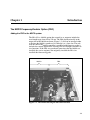
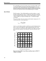
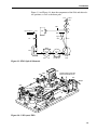

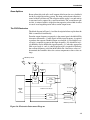
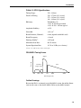

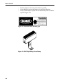
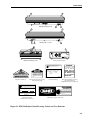
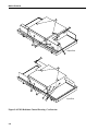

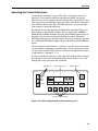
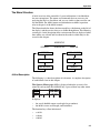
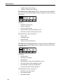
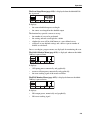
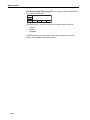
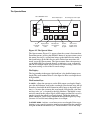
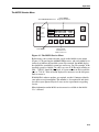
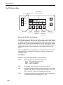

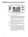
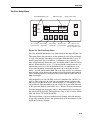
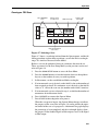
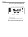
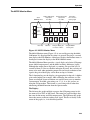

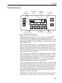
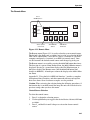
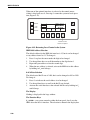

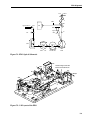

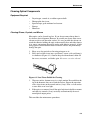


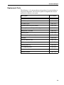

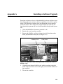
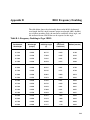
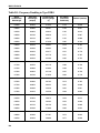
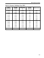

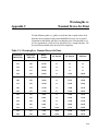
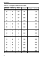
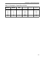

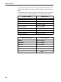

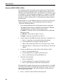
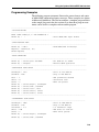
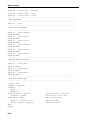
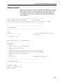
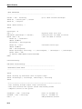
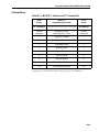
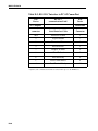
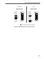


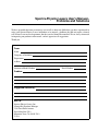


![manual [372769 bytes]](http://vs1.manualzilla.com/store/data/005891066_1-6553408cfa4c941a2bbbbb48a824c132-150x150.png)