1
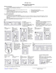
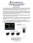
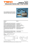
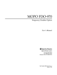
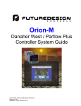
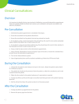
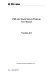
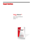
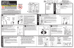
nCompass MC Multiloop Control System, Specifications, Part Number Matrix April 2015 What is nCompass MC? The nCompass MC Control system combines all of the features of typical loop controllers, video/chart recorders and data logging systems into a single, intuitive device. nCompass provides a 4.3” color touch screen interface with standard OEM configurable runtime features for supporting single to up to ten loop controls, with the runtime configurable at the device with no PC software required. nCompass supports one to ten high performance board level PID loop control boards each offering up to 4 control outputs, powerful profiling capabilities with nCompass also providing Data Logging, Alarm management, Security, Audit Trail, powerful LAN functions and as standard serial modbus communications for remote devices or software . Profile (Ramp/Soak) logic allows each loop to run independent profiles or as a Master/Slave where the profile setpoint values in the Master loop are sent to the slave controls. Integrated LAN features include email/SMS messaging upon alarm, FTP (file transfer protocol) for automated file transfer/data backup, remote access (web and VNC embedded servers), national timeserver time synchronization and more are standard. The web and VNC servers allow remote access using a PC, tablet or smart phone. nCompass is OEM Friendly! nCompass is OEM friendly providing a system import/export utility as well as an OEM configurable “reset default configuration” utility to allow the end user to reset the system to the OEM’s configuration settings. If you can use a Consumer Phone or Tablet, you can use nCompass! User configurable with “slide nav” finger navigation similar to consumer phone and tablets or with a traditional drop down menu system, nCompass is intuitive to operate and use. With one touch language configuration for all icons, menus and help screens, nCompass provides ease of use in any one of 28 languages. FDC nCompass - MC Matrix April 2015 Page 1 of 4 How to Order nCompass MC is ordered as 3 to 12 components dependent upon the number of control loops, one to ten. nCompass MC Sample Part Numbers (minimum of 3 component part numbers is required; (1) display, (2) firmware, (3) loop #1) (dual loop shown) Item # Product 1 Display Sample Part Number FDC-0450-1011-000BN Description 4.3” display, MC software, 11-36 VDC power input, SD slot, Ethernet, standard enclosure 2 MC Firmware SD-MC MC Loop Control Firmware (inserted into display SD slot) 3 Loop #1 B42-4166-11D0 -CA 90-250VAC power input, T/C or RTD input, output #1 1A Triac, 12 Loop #10 B42-4366-11D0 -CJ 90-250VAC power input, mA input, output #1 1A Triac, output #2 1A Triac, output #3 relay, output #4 relay, comms, no display Options Power Supply PS5R-SB24 Cable 85-264VAC power input, Output 24VDC 15W (0.6A) CA2011-3D Item #1 FDC - 0450 – Order Matrix # Cable from display to B42 (DB25 connector (display), twisted pair leads (B42), shielded (10ft) Model FDC - 0450 4.3” Color Touch Screen 1 0 1 1 0 0 0 B N 1 2 3 4 5 6 7 8 9 (1) Power Input 1: 11 to 36 VDC (6) Software 0: None (2) Sound Output 0: None (7) Enclosure 0: Standard (3) SD Card Slot 1: Yes (8) Special B: Black Overlay (4) Ethernet 1: Yes (9) Special N: Neutral Overlay (no name/logo) (5) Network 0: None Item #2: Loop Control Firmware Order Matrix # SD - Price: included with Display MC (Fixed characters SD-MC: SD card with MC (Multi-Loop Control) Display Configuration and SD plugged into display) Control System Options (ordered separately as appropriate) Cable: Display to B42 Control Board CA2011-3D: Cable (10ft) from Display to B42 controller. Note: Consult factory for other lengths & options) Display Power Supply (input 100-240VAC / Output 24VDC) DIN Rail Mount: PS5R-SB24: 15W power supply Open Frame: PS3X-B24AFC: 15W power supply Note: Either of the above will power the FDC-0450 touch screen display USB Memory Stick UDF115-2GB: (2GB High Capacity USB Memory Stick (3VDC)) System Reset Timer GE1A-C10HA110/SR2P-06: Reset Timer and socket (DIN Rail) Note: Timer is recommended for proper system restart due to momentary power interruptions (<500ms) which can erroneous operation. Relays for Dual Loop with Guaranteed Soak/Holdback RJ2S-CL-A120: DPTD Relay 8A 120VAC SJ2S-05BW: DIN socket relay for RJ2 relay B42 Programming Display Board B42 Display Board 300 mm cable: 3020B42-00300A-00/300 B42 Display Board 1000mm cable: 3020B42-00300A-00/1K Printed Operators Manual Part Number (Orion-nCompass_MC_i4.3_User_Manual.pdf) FDC-Orion nCompass MC i4.3 User Manual Printed Configuration Manual Part Number (Orion-nCompass_MC_i4.3_Config_Manual.pdf) FDC-Orion nCompass MC i4.3 Configuration Manual Printed Communication Reference Manual Part Number (Orion-nCompass_MC_i4.3_Comm Reference.pdf) FDC-Orion nCompass MC i4.3 Communication Reference Manual USB Cables & Accessories IStick-4X-CVR USB Panel Mount Adapter-Nema4x USB Cable/Panel Consult factory for referral to low cost cables FDC nCompass - MC Matrix April 2015 Page 2 of 4 Item #3: B42 Loop Control Board - Loop 1 B42 Order Matrix # 1 B42 – D 2 3 4 5 6 7 Item #4-12: B42 Loop Control Board - Loop 2 -10 8 9 Order Matrix # 1 D 2 3 4 5 6 7 8 (1) Power Input 4: 90-250 VAC, 47-63 HZ 5: 11-26 VAC or VDC (1) Power Input 4: 90-250 VAC, 47-63 HZ 5: 11-26 VAC or VDC (2) Signal Input (18-bit A/D) 1: Standard Input Thermocouple: J, K, T, E, B, R, S, N, L, C, P RTD: PT100 DIN, PT100 JIS Voltage: 0-60mV 5: 0-10V, 0-1V, 0-5V, 1-5V 6: 0-20/4-20mA 9: Special Order (2) Signal Input (18-bit A/D) 1: Standard Input Thermocouple: J, K, T, E, B, R, S, N, L, C, P RTD: PT100 DIN, PT100 JIS Voltage: 0-60mV 5: 0-10V, 0-1V, 0-5V, 1-5V 6: 0-20/4-20mA 9: Special Order (3) Output 1 0: None 1: Relay rated 2A/240VAC (SPST) 2: SSR Driver 5 VDC @ 30 Ma 3: 4-20mA / 0-20mA Isolated 4: 1-5V / 0-5V/0 - 10V Isolated 6: Triac output 1A / 240VAC, SSR C: SSR Driver 14 VDC @ 40 Ma (3) Output 1 0: None 1: Relay rated 2A/240VAC (SPST) 2: SSR Driver 5 VDC @ 30 Ma 3: 4-20mA / 0-20mA Isolated 4: 1-5V / 0-5V/0 - 10V Isolated 6: Triac output 1A / 240VAC,SSR C: SSR Driver 14 VDC @ 40 Ma (4) Output 2 0: None 1: Relay rated 2A/240VAC (SPST) 2: SSR Driver 5 VDC @ 30 Ma 3: 4-20mA / 0-20mA Isolated 4: 1-5V / 0-5V/0-10V Isolated 6: Triac output 1A / 240VAC, SSR 7: Transmitter power supply 20 VDC/25 ma Isolated 8: Transmitter power supply 12 VDC/40 ma Isolated A: Transmitter power supply 5 VDC/80 ma Isolated C: SSR Driver 14 VDC @ 40 Ma (4) Output 2 0: None 1: Relay rated 2A/240VAC (SPST) 2: SSR Driver 5 VDC @ 30 Ma 3: 4-20mA / 0-20mA Isolated 4: 1-5V / 0-5V/0-10V Isolated 6: Triac output 1A / 240VAC, SSR 7: Transmitter power supply 20 VDC/ 25 ma Isolated 8: Transmitter power supply 12 VDC/40 ma Isolated A: Transmitter power supply 5 VDC/80 ma Isolated C: SSR Driver 14 VDC @ 40 Ma (5) Output 3 0: None 1: Relay rated 2A/240VAC (SPST) 2: SSR Driver 5 VDC @ 30 Ma 6: Triac output 1A / 240VAC, SSR 7: Transmitter power supply 20 VDC/25 ma Isolated 8: Transmitter power supply 12VDC/40 ma Isolated A: Transmitter power supply 5VDC/80 ma Isolated C: SSR Driver 14 VDC @ 40 Ma (5) Output 3 0: None 1: Relay rated 2A/240VAC (SPST) 2: SSR Driver 5 VDC @ 30 Ma 6: Triac output 1A / 240VAC, SSR 7: Transmitter power supply 20 VDC/25 ma Isolated 8: Transmitter power supply 12VDC/40 ma Isolated A: Transmitter power supply 5VDC/80 ma Isolated C: SSR Driver 14 VDC @ 40 Ma (6) Output 4 0: None 1: Relay rated 2A/240VAC (SPST) 2: SSR Driver 5 VDC @ 30 Ma 3. Retransmission 4-20 / 0-20mA, isolated 4. Retransmission 1-5 / 0-5 / 0-10VDC, isolated 6: Triac output 1A / 240VAC, SSR 7: Transmitter power supply 20 VDC/25 ma Isolated 8: Transmitter power supply 12VDC/40 ma Isolated A: Transmitter power supply 5VDC/80 ma Isolated C: SSR Driver 14 VDC @ 40 Ma (6) Output 4 0: None 1: Relay rated 2A/240VAC (SPST) 2: SSR Driver 5 VDC @ 30 Ma 3. Retransmission 4-20 / 0-20mA, isolated 4. Retransmission 1-5 / 0-5 / 0-10VDC, isolated 6: Triac output 1A / 240VAC, SSR 7: Transmitter power supply 20 VDC/25 ma Isolated 8: Transmitter power supply 12VDC/40 ma Isolated A: Transmitter power supply 5VDC/80 ma Isolated C: SSR Driver 14 VDC @ 40 Ma (7) Output 5 D: RS-485 Modbus RTU interface Isolated (7) Output 5 D: RS-485 Modbus RTU interface Isolated (8) Display Board and cable 0: None 3: Display Board with 300mm connection cable 4: Display Board with 1000mm connection cable (8) Display Board and cable 0: None 3: Display Board with 300mm connection cable 4: Display Board with 1000mm connection cable $45.00 $45.00 (9): Modbus Addressing: (if blank factory default is Modbus address #1) CA: Modbus Comm Address #1 CB: Modbus Comm Address #2 CC: Modbus Comm Address #3 Note that field configuration of Comm address requires the optional Display 9 (9): Modbus Addressing: (if blank factory default is Modbus address #1) CA: Modbus Comm Address #1 CD - CJ: Modbus CB: Modbus Comm Address #2 Comm Address #4-#10 CC: Modbus Comm Address #3 Note that field configuration of Comm address requires the optional Display FDC nCompass - MC Matrix April 2015 Page 3 of 4 NOTES: SCADA (Supervisory Control & Data Acquisition) NOTES: Profile Ramp / Soak and Batch Timer Specifications FDC-nCompass Series Graphic User Interface (GUI) touch screen provides a full SCADA feature set providing ease of use with either an icon menu system with finger navigation or traditional Menu bar, data acquisition, alarm manager, operator audit trail, multi-level security with user rights, LAN connections and more. The GUI provides ease of configuration, use & support. - System Configuration for loop, alarm, input & outputs assignment, language selection and more, all without an external device or PC. - Loop Views: view 1 or 2 controls in single or dual view as well as in a Trend format (trend up to loop controls PV, SP & Percent Out). - Profile: Virtually unlimited number of profiles with each profile having up to 64 steps with up to 6 events (3 per loop). - File Management: View and copy/move/delete Profile, Alarm, Historical Data (data log files) and operator audit trial files. File transfer via LAN features (FTP or email) or USB flash memory LAN (Local Area Network Features: Remote Access & touch screen operation (VNC), email/SMS on alarm, email historical, alarm & audit trail files on-demand, Web Page (view only) and FTP of alarm, audit and historical data files automatically or on-demand. Email & FTP ports are configurable. Data Acquisition: - Data log PV, SP and PID Percent output for 1 or 2 loop controls. - Data Log interval: configurable 2-seconds to 31-minutes. - File Start/Stop: Configurable; operator on-demand, on system boot or profile ramp-soak start/end. - File Interval: Once started a data log file is configurable to auto end and start a new file with the same name as previous file with an appended time/date name. Configurable time interval is from 1 to 31 days. - File name: Operator entered file name, batch & lot information or if Started with a profile, file name is the same as profile name. (all file names appended with date-time to the second.) - Operator Comments/Events: Unlimited operator comments/events linked to each file entered manually or via Bar Code Scanner. - File Type: Data Log files are saved in .csv format. - Digital Signatures: Automatic system signature as well as user entered digital signatures for each data file are supported. Digital Signatures allow the data file to be validated (data has not been altered). Files may be validated on the display or on a PC with Orion Data Viewer - Historical Data File: View data log files on the display. Chart is autoscaled on an X & Y axis for time and units. After data is copied/moved via LAN (FTP or email) or USB Memory, may be viewed on PC utilizing Excel or FDC’s free Orion Data Viewer. Security and Audit Trail: - Supports up to 30 users over four user groups with access to over 40 functions restricted by user group. - Supports password aging and authentication. - Operator Audit Trail file provides history of all actions affecting the system that action is written to a file with the user name and date. Profile Ramp/Soak: - Profiles: Virtually an unlimited number of profiles in system memory - Profile Type: Time Based Ramp and Soak. System configurable for separate profiles per loop or common profile with slave set point operation for other loops. - Profile Start: via touch screen or Event input (see above). - Profile Name: Free form 16 character (max) naming convention with auto append time/date stamp. - Global Profile Configuration - Profile Time Base: Time Ramp (hh:mm or mm:ss) Ramp Rate (degrees/minute or hour) - Starting and Ending SP values (may be individually active or not). - Guaranteed Soak & Ramp (GS): - Range 1 to 999F (555C), configurable per step as low, high, band or inactive (disable). - Power Fail / Recovery when Profile is active: - Continue from last SP value. - Continue from last PV value. - Static mode (abort profile) with last static SP entry. - Profile Segments: (maximum of 64) - Jump To Segment: configurable by segment (also nested looping) - Events: up to 3 events* per segment. - Guaranteed Soak & Ramp: Configurable active or not by segment. * Note: The number of events available is predicated on the control board hardware, number of control boards and configuration. - Profile End Logic: - Profile End Alarm (configurable - relay enabled at Profile End) - Configurable Profile End Logic: - Current (Static) Control SP: The Set Point & Event status prior to Profile Start is loaded at end of the Profile. - Final SP of Profile (all Events off (not profile end output) - B42 Event Input ** (EI): - Configurable functions below (mutually exclusive to each other) - Profile Run (momentary) - Profile Hold (closed profile hold, open profile run) - Profile Run/Hold (closed profile run, open profile hold) - Step Advance (momentary) - Profile Abort (momentary) - PID Selection: select PID #1 or PID#2 ** Above are profile specific EI; additional functions are available. Although the Event Input provides a manner to control Profile functions remotely, typically Profile actions would have the Operator using the intuitive easy to use 4.3” color touch screen (operator interface). NOTES: Power Supply – Optional Power Capacity Required (Watts) - A base system requires ~10 watts of 24Vdc power for the nCompass user interface. The 15W power supplies offered are sufficient to power display only. NOTES: B42 Control Board (1 to 10 may be used) B42 Loop Control: http://www.futuredesigncontrols.com/B42.HTM - Analog Input: 200ms scan rate with 18-bit A/D resolution providing high accuracy and PID control performance - Outputs: Maximum of 4 control or auxiliary outputs - PID Control Outputs: up to 2 with Auto Tune capability (heat-cool) Relay, SSR driver 5V, SSR driver 14V, 1A SSR, mA* or VDC* - Alarm or Event: up to 3 outputs (outputs #2, #3 & #4) Relay, SSR driver 5V, SSR driver 14V or 1A SSR - Auxiliary Outputs: up to 2 outputs, one or two Transmitter power supplies and/or one Retransmission* output *Note: Analog mA and VDC PID and retransmit outputs are 15-bit, contributing to high performance PID control and highly accurate retransmitted PV or SP values. - Alarm Types: Process, Deviation and Deviation Band, all High or Low - PID Parameters: Two sets of PID values may be configured and selected by Profile Step and/or by digital event input. (see next) - Event Inputs: Configurable for one of the following functions. - Profile Run (momentary) - Profile Hold (closed profile hold, open profile run) - Profile Run/Hold (closed profile run, open profile hold) - Profile Abort (momentary) - Segment Advance (momentary) - Manual Mode (closed manual mode, open normal control) - Failure Transfer: (closed failure transfer, open normal control) (transfer active %Out is a pre-configured value for each output) Note: The power supply should be used to power nCompass components only and not OEM or other end user components or devices. NOTES: Language Configuration nCompass provides a one-button language configuration for the following languages. - Afrikaans - Albanian - Arabic - Basque - Belarusian - Chinese (simplified) - Chinese (traditional) FDC nCompass - MC Matrix April 2015 Page 4 of 4 - Czech - Danish - Dutch - English - Finnish - French - German - Greek - Hebrew - Hungarian - Icelandic - Italian - Japanese - Korean RoHS Compliant - Norwegian - Polish - Portuguese - Russian - Spanish - Swedish - Turkish