1
RACETIME 2
User Manual
The Racetime 2 System
The Linkgate System
Single Start and Group Start Program
Simple Stopwatch Program
Release. 2.10
Microgate S.r.l.
Via Stradivari, 4
I-39100 BOLZANO - ITALY
RACETIME 2
2
Index
THE RACETIME 2 SYSTEM .....................................................................................................6
1
OVERVIEW ............................................................................................................................7
1.1 RACETIME 2 .................................................................................................................7
1.2 THE PRINTER ...............................................................................................................8
1.3 BACK VIEW ..................................................................................................................9
1.4 LINKGATE ENCODER...............................................................................................10
1.5 LINKGATE DECODER...............................................................................................11
1.6 CONNECTION BOX ...................................................................................................12
2 CONNECTION DIAGRAMS ..........................................................................................13
2.1 TIMING VIA CABLE ..................................................................................................13
2.2 TIMING VIA RADIO...................................................................................................15
2.2.1
2.2.2
2.2.3
2.3
TIMING VIA RADIO...................................................................................................18
2.3.1
2.3.2
2.3.3
2.4
2.5
2.6
2.7
2.8
Free along the Track ............................................................................................... 16
Radio-Encoder-Gate Connection....................................................................... 17
Radio-Encoder-Photocell Connection ............................................................. 17
Free along the track ................................................................................................ 19
EncRadio – Gate Connection .............................................................................. 20
Radio-Encoder-Photocell Connection ............................................................. 20
DISPLAYBOARD CONNECTION .............................................................................21
MEASURING SPEED..................................................................................................22
CONNECTING THE BATTERY CHARGER.............................................................23
CONNECTORS ............................................................................................................24
CONNECTION CABLES.............................................................................................25
THE LINKGATE SYSTEM ......................................................................................................30
3
4
INTRODUCTION.............................................................................................................31
LINKGATE ENCODER : 3 FEATURES GUARANTEEING THE RELIABILITY OF RADIO
TRANSMISSION ...........................................................................................................................32
4.1 DIGITAL TRANSMISSION OF IMPULSES..............................................................32
4.2 THE REPEAT FUNCTION..........................................................................................32
4.3 INTERNAL MEMORISATION OF EVENT TIMES..................................................32
5 USING YOUR LINKGATE ENCODER........................................................................33
5.1 SELECTING THE CHANNEL ....................................................................................33
5.2 SELECTING THE TYPE OF SIGNAL........................................................................33
5.3 IMPULSE TRANSMISSION .......................................................................................33
5.4 THE REPEAT FUNCTION..........................................................................................34
5.5 CALCULATING A SPEED .........................................................................................34
5.6 HARDWARE RESETTING .........................................................................................34
5.7 RESETTING THE MEMORY .....................................................................................35
5.8 SYNCHRONIZATION.................................................................................................35
RACETIME 2
3
5.9 DOWNLOADING DATA onto RACETIME2.............................................................35
5.10 THE MODEM FUNCTION.........................................................................................36
5.11 MAINTENANCE.........................................................................................................36
PROGRAMS................................................................................................................................38
6
7
INSTRUCTIONS FOR READING THE MANUAL .......................................................................39
GENERAL INFORMATION ....................................................................................................40
7.1 FUNCTION AND CE KEY USE .................................................................................41
7.2 NUMERICAL DATA INPUT ......................................................................................41
7.3 SWITCHING ON THE MACHINE .............................................................................42
SINGLE START AND GROUP START PROGRAM............................................................44
8 SINGLE START AND GROUP START MODES .......................................................................45
9 MAIN MENUS ......................................................................................................................47
10
TIMING ..........................................................................................................................48
10.1 INSERTION/CORRECTION FUNCTION .................................................................49
10.1.1 Start number insertion/correction...................................................................... 49
10.1.2 Finish number insertion/correction................................................................... 50
10.1.3 Use of keys ↑ ↓ ............................................................................................................ 50
10.1.4 Turning the Autoskip function on and off........................................................ 51
10.1.5 Skipped management (SkM) ................................................................................. 51
10.1.6 Editing or displaying intermediate times ........................................................ 52
10.1.7 Cancelling Skipped events memory. .................................................................. 52
10.1.8 Activation/disactivation of automatic assignment of finishes and
intermediate times on and off ............................................................................................. 52
10.1.9 Returning to the main menu ................................................................................. 53
10.1.10
Returning to the main menu during timing ........................................... 53
10.2 MANAGEMENT OF EVENTS...................................................................................54
10.2.1
10.2.2
10.2.3
10.2.4
10.2.5
10.2.6
Displaying starts ....................................................................................................... 54
Finishes management .............................................................................................. 55
Intermediate time management ........................................................................... 57
Displaying speeds transmitted by the LINKGATE Encoder ................... 58
Display of average speeds ..................................................................................... 58
LCK key use ................................................................................................................ 59
11
INTERPRETATION OF PRINTED DATA DURING TIMING...........................60
12
GROUP MANAGEMENT ..................................................................................................62
12.1 RANKINGS FOR FINISH TIMES, INTERMEDIATE TIMES AND SPEED ..........64
12.1.1 Viewing on the screen ............................................................................................. 65
12.1.2 Printing the ranking ................................................................................................. 65
12.2
12.3
12.4
13
14
15
16
17
17.1
INTERMEDIATE TIME RANKINGS ........................................................................66
SPEED RANKINGS ....................................................................................................67
PRINTING EVENT TIMES, NP, NF, DISQUALIFIED, SKIPPED ..........................68
AUTOMATIC STARTS .............................................................................................69
DISQUALIFICATIONS/REINSTATEMENTS ......................................................70
SYNCHRONIZATION...............................................................................................71
OFF-LINE DATA TRANSMISSION........................................................................72
SYSTEM CONFIGURATION...................................................................................73
RACETIME configuration ...........................................................................................73
RACETIME 2
4
17.1.1 Time display mode .................................................................................................... 73
17.1.2 Event times printout ................................................................................................. 73
17.1.3 Automatic finish search .......................................................................................... 73
17.1.4 Net time print mode ................................................................................................ 73
17.1.5 Maximum time ............................................................................................................ 73
17.1.6 Measurement accuracy ........................................................................................... 73
17.1.7 Modifying ‘dead’ times ........................................................................................... 74
17.1.8 Activating the LCK key ........................................................................................... 74
17.1.9 LINKGATE channel ................................................................................................. 74
17.1.10
Setting of serial transmission parameters ............................................. 75
17.1.11
Activation/disactivation of the printer and of acoustic signalling
when keys are pressed ........................................................................................................... 75
17.1.12
Initialization of configuration ..................................................................... 75
17.2 SKITEST CONFIGURATION ....................................................................................76
17.2.1
17.2.2
17.2.3
17.2.4
‘Radio’ speed base length ..................................................................................... 76
‘Average’ speed base length................................................................................. 76
Speed measurement unit......................................................................................... 76
Temperature and humidity probe tests ............................................................. 77
17.3 DISPLAYBOARD CONFIGURATION .....................................................................78
17.3.1 Displayboard type..................................................................................................... 78
17.3.2 Displayboard number ............................................................................................. 78
17.3.3 Advertising ................................................................................................................... 78
18
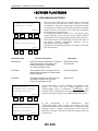
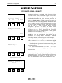
OTHER FUNCTIONS................................................................................................79
18.1 RECHARGING BATTERIES .....................................................................................79
18.1.1
18.2
18.3
19
19.1
Low batteries warning...................................................................................................... 80
MEMORY LIMITS......................................................................................................80
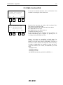
RECEIVING DATA FROM LINKGATE ...................................................................81
RADIO SIGNAL QUALITY......................................................................................83
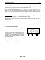
TIME CALCULATOR.................................................................................................84
SIMPLE STOPWATCH PROGRAM ......................................................................................86
20
SIMPLE STOPWATCH PROGRAM ......................................................................87
21
TIMING .......................................................................................................................89
22
SETTING INITIAL TIME (START TIME) ............................................................91
23
VIEWING OF MEMORISED TIMES .....................................................................92
24
DISPLAY OF TIMES ON THE MICROGATE ALPHANUMERIC
DISPLAYBOARD....................................................................................................................92
25
DATA TRANSMISSION............................................................................................93
26
SYSTEM CONFIGURATION...................................................................................94
26.1 Racetime CONFIGURATION .....................................................................................94
26.1.1 Measurement accuracy ........................................................................................... 94
26.1.2 Modifying ‘dead’ times ........................................................................................... 94
26.1.3 LINKGATE channel ................................................................................................. 94
26.1.4 Setting of serial transmission parameters ...................................................... 96
26.1.5 Activation/deactivation of the printer and of acoustic signalling when
the keys are pressed ................................................................................................................ 96
26.1.6 Initialization configuration ................................................................................... 96
RACETIME 2
5
26.2 Setting the length for speed calculation........................................................................97
26.3 DISPLAYBOARD CONFIGURATION .....................................................................98
26.3.1 Displayboard type..................................................................................................... 98
26.3.2 Number of displayboards....................................................................................... 98
26.3.3 Advertising ................................................................................................................... 98
27
27.1
27.2
27.3
OTHER FUNCTIONS................................................................................................99
RADIO SIGNAL QUALITY .......................................................................................99
time calculator ............................................................................................................100
Recharging batteries ...................................................................................................101
27.3.1 Low batteries warning .......................................................................................... 102
APPENDIX ................................................................................................................................105
28
29
2.1
29.1
29.2
30
30.1
30.2
30.3
31
TECHNICAL DATA ................................................................................................106
RACETIME2 TRANSMISSION PROTOCOL ....................................................................108
BINARY TRANSMISSION .......................................................................................108
ASCII TRANSMISSION ...........................................................................................110
ON-LINE transmission during timing........................................................................112
DATA FORMAT FOR THE TRANSFER OF DATA STORED IN THE LINKGATE ENCODER 113
HEADER ....................................................................................................................113
DATA FRAME ..........................................................................................................113
SERIAL PORT SETTING .........................................................................................113
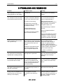
PROBLEMS AND REMEDIES ..............................................................................114
THE RACETIME 2
SYSTEM
RACETIME 2 – Linkgate System
7
1 Overview
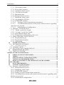
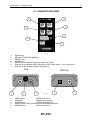
1.1 RACETIME 2
11
1
10
2
9
3
8
4
7
5
6
Fig. 1
1.
2.
3.
4.
5.
6.
7.
8.
9.
10.
11.
Alphanumeric display (4 lines, 20 colums) with a range width of –30 C +70 C
Function keys (F1,F2,F3,F4)
CE key (control/paper feed)
START key
STOP key
LOCK key
Arrow ↑↓ (running through times)
Case in ABS
LAP key
ENTER key
Numeric keyboard (0..9)
RACETIME 2 – Linkgate System
8
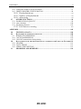
Inserting the
printer
1.2 THE PRINTER
Ð Ð Ð
Fig. 2
Changing the printer
cartridge
Changing the paper
roll
Ï
Ï
Opening the printer compartment
The printer
Ó Press
Ó
Press to remove printing cartridge
Fig. 3
Opening paper roll compartment
Fig. 4
RACETIME 2 – Linkgate System
9
4
3
5
2
6
1
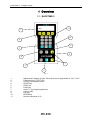
Fig. 5
1.3 BACK VIEW
1.
2.
3.
4.
5.
6.
Case in ABS
15 pole female CANNON panel connector
Red LED
Power point for battery charger
ON/OFF switch
5 pole male panel connector
RACETIME 2 – Linkgate System
10
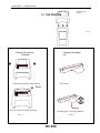
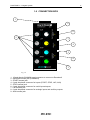
1.4 LINKGATE ENCODER
1
3
LINKGATE
E N C O D E R
SIGNAL
2
REPEAT
SYN
RESE
SYNC
RESET
2ND
MODEM
4
SERIAL
5
SIGNAL TYPE
6
SHORT
IMPULSE
LONG
7
CHANNEL
Fig. 6
1.
2.
3.
4.
5.
6.
7.
SIGNAL key
SECOND FUNCTION (2ND) key
REPEAT key
MODEM key
Selector for transmitted signal type (Start, Lap, Stop)
Selector for transmitted signal redundancy (High, short signal – Low, long signal)
Selector for transmission channel (Dip Switch)
Top
1
1.
2.
3.
4.
5.
2
Bottom
3
Fig. 7
4
SPEED input
(RED banana jack)
GROUND
(BLACK banana jack)
SIGNAL input
(GREEN banana jack)
Power point for radio connection and serial data download
MODEM input
(BLU banana jack)
5
RACETIME 2 – Linkgate System
11
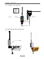
1.5 LINKGATE DECODER
2
Fig. 8
1
Bottom
Top
3
Fig. 9
1. Connection cable for Racetime2 (female 5 pole movable connector)
2. Loudspeaker
3. Cable output to connect with Racetime2
4. 3 pole male connector
4
RACETIME 2 – Linkgate System
12
1.6 CONNECTION BOX
1
9
8
2
7
6
5
4
3
Fig. 10
1.
2.
3.
4.
5.
6.
7.
8.
9.
15 pole female CANNON panel connector to connect to Racetime2
GROUND banana jack (COMMON)
START banana jack
6 pole Amphenol connector for inputs (START, STOP, LAP, AUX)
STOP banana jack
6 pole Amphenol connector for serial inputs/outputs
LAP banana jack
6 pole Amphenol connector for analogic inputs and auxiliary outputs
AUX banana jack
RACETIME 2 – Linkgate System
13
2 CONNECTION DIAGRAMS
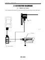
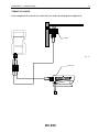
2.1 TIMING VIA CABLE
Gate and photocell connected to connection box with the photocell powered by Racetime 2
Gate
Fig. 11
Polifemo
Connextion Box
RACETIME 2 – Linkgate System
14
TIMING VIA CABLE
Gate and photocell connected to connection box with externally powered photocell
Gate
Fig. 12
Photocell
RACETIME 2 – Linkgate System
15
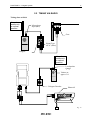
2.2 TIMING VIA RADIO
Taking data at finish
Keep the
antenna in
a vertical
position
Microphone
input (Mic)
Gate
S
R
Signal Type
on “0” (Start)
Linkgate
Keep the
antenna in
a vertical
position
Loudspeaker
Output
( )
Volume at
approx 3/4
Linkgate Decoder
Photocell
Fig. 13
RACETIME 2 – Linkgate System
16
2.2.1 Free along the Track
Taking data from anywhere along the track
Fig. 14
RACETIME 2 – Linkgate System
17
2.2.2 Radio-Encoder-Gate Connection
S
R
Fig. 15
2.2.3 Radio-Encoder-Photocell Connection
S
Linkgate Encoder
R
Fig. 16
RACETIME 2 – Linkgate System
18
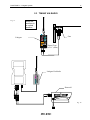
2.3 TIMING VIA RADIO
Fig. 17
Keep the
antenna in
a vertical
position
Gate
Linkgate
Signal Type
on “0” (Start)
Linkgate DecRadio
Photocell
Fig. 18
RACETIME 2 – Linkgate System
19
2.3.1 Free along the track
Taking data anywhere along the track
Fig. 19
RACETIME 2 – Linkgate System
20
2.3.2 EncRadio – Gate Connection
Keep the
antenna in
a vertical
position
Gate
Linkgate
Signal Type
on “0” (Start)
Fig. 20
2.3.3 Radio-Encoder-Photocell Connection
Fig. 21
Linkgate
RACETIME 2 – Linkgate System
21
2.4 DISPLAYBOARD CONNECTION
Fig. 22
9-digit MICROTAB
Alphanumeric
displayboard
Connection Box
Serial 1
Serial in/out
RACETIME 2 – Linkgate System
22
2.5 MEASURING SPEED
Fig. 23
Speed base
running
direction
Linkgate
Encoder
Photocell
S
Speed base
input on RED
banana box
R
Length of
speed
base
Speed base
output on
GREEN
banana box
Photocell
RACETIME 2 – Linkgate System
23
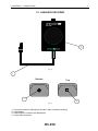
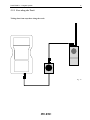
2.6 CONNECTING THE BATTERY CHARGER
Recharging
status indicator
(see Chap. C10)
Supply socket
Ï
Ï
Fig. 24
Supply unit
Supply jack
Permitted voltage 12-20
VDC
Polarity: any
RACETIME 2 – Linkgate System
24
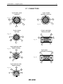
2.7 CONNECTORS
5 pole male panel
connector
3 pole female
movable connector
Fig. 25
5
1
2
1
3
2
Fig. 26
4
3
5 pole female
movable
15 pole male high
density movable
Fig. 27
1
1
5
5
10
6
Fig. 28
4
2
3
11
15
6 pole male movable
Amphenol plug
Fig. 29
3
9 pole male
movable CANNON
2
4
1
1
5
5
Fig. 30
6
6
5 pole male movable
Amphenol plug
3
Fig. 31
4
5
2
1
9
RACETIME 2 – Linkgate System
25
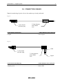
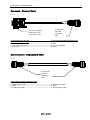
2.8 CONNECTION CABLES
Note: the numbering of poles refers to the numbers previously indicated.
Fig. 32
5 pole female
movable plug
2.5mm diameter
mono Radio
Jack
5 pole female movable plug
2.5mm diameter mono radio jack
1.GND ------------------------------------------------------------------------------ Base= GND
2.Signal----------------------------------------------------------------------------- Point= Signal
Fig. 33
GND
3 pole female
movable plug
3.5 mm diameter
mono Radio
Jack
Signal
3 pole Female movable plug
3.5mm diameter mono radio jack
1 Signal----------------------------------------------------------------------------- Point= Signal
3 Signal ground------------------------------------------------------------------- Base= GND
RACETIME 2 – Linkgate System
26
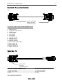
Linkgate Encoder – Racetime2 Cable (for serial download of data)
Fig. 34
5 pole female
movable plug
15 pole male high
density movable
CANNON socket
5 pole female movable plug
15 pole male high density movable CANNON socket
4. Photo coupler emitter------------------------------- 15. Asynchronic serial, RX
5. Serial photo coupler collector--------------------- 2. +5 Vcc
12. Connected with 3900 Ohm resistance to pin 15
Encoder – Photocell/Gate
Fig. 35
RACETIME 2 – Linkgate System
27
Racetime2 – Connection Box Cable
Fig. 36
15 pole male high
density movable
CANNON socket
15 pole male high density movable CANNON socket
1. Digital ground
2. +5 Vcc out, max 500 mA
3. START signal
4. STOP signal
5. LAP signal
6. AUX signal
7. Analogic input 2
8. Analogic input 1
9. Analogic input 0
10. Analogic ground
11. Sync. serial, clock output
12. Sync. serial, TX
13. Sync. serial, RX
14. Async. serial, TX
15. Async. serial, RX
Power Box - PC
Fig. 37
9 pole male
movable
CANNON socket
9 pole male movable CANNON socket
6 pole male movable Amphenol plug
2. Serial input (RXD) ---------------------------------------------------1. Serial output (TXD)
3. Serial output (TXD)---------------------------------------------------6. Serial input (RXD)
5. GND --------------------------------------------------------------------- 5. GND
1+4+6 connected to each other
7+8 connected to each other
RACETIME 2 – Linkgate System
28
Racetime2 – Photocell Cable
Fig. 38
15 pole male high
density movable
CANNON socket
5 pole male
movable
Amphenol
plug
15 pole male high density
5 pole male movable Amphenol plug
movable CANNON socket
1.Digital Ground ----------------------------------------------------------3.GND
2.+5 Vcc out, max 500 mA --------------------------------------------2.+5V Vcc stabilized
4.Stop Signal--------------------------------------------------------------5.STOP
Connection box – Displayboard Cable
Fig. 39
6 pole male
movable
Amphenol
plug
6 pole male movable Amphenol plug
1 .Serial Output (TXD) --------------------------------------------------6. Serial Input (RXD)
5. GND --------------------------------------------------------------------- 5. GND
6. Serial Input (RXD) ----------------------------------------------------1. Serial Output (TXD)
NOTES
THE LINKGATE
SYSTEM
RACETIME 2
31
3
INTRODUCTION
The transmission of an impulse via radio is a critical phase in timekeeping. The possibility of losing the
data transmitted, of having very inaccurate timing and the transmission difficulties in some zones has
often made timekeepers and trainers skeptical about this type of approach.
The LINKGATE Encoder system represents a radical innovation in the field of radio transmission of
impulses for timekeeping. Technological evolution has enabled us to go from the old impulse
transmission systems to the more modern data transmission concept, which can guarantee extreme
accuracy, the transmission of large quantities of information and greater reliability. In addition, the
compact size of the system and the possibility of using it with any type of VHF or UHF transmitter radio
makes the LINKGATE Encoder the ideal instrument for training and competitions at every level.
RACETIME 2
32
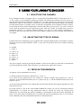
4 LINKGATE ENCODER : 3 features guaranteeing
the reliability of radio transmission
To overcome unreliability and the various problems associated with the old system of radio transmission
of impulses, LINKGATE Encoder offers a number of innovative solutions.
4.1 DIGITAL TRANSMISSION OF IMPULSES
Linkgate Encoder transmits sets of data (no longer a single impulse) that contain a vast amount of
information. In particular, the following are transmitted:
-
The transmitter’s Code (which can be selected with the Channel Select switches)
The Type of signal transmitted (Start, Lap number or Finish, which can be selected with the
Signal Type switch)
How long ago the event took place
The running Time of a speed base (if present)
In addition, the kit contains numerous control codes and error auto-correction codes which prevent a
signal from being incorrectly interpreted during reception.
All the data (information + control codes) is transmitted 16 times, in order to reduce the possibility of
reception failure.
Even with very disturbed signal transmission, this system ensures maximum reliability and precision (+/0.4 thousandths of a second); in short, you only need the complete reception of a single set of data to be
able to reconstruct the original time of the event.
4.2 THE REPEAT FUNCTION
If there are any problems in data reception, (radio malfunction, interference from a more powerful
transmission, a cable which comes unplugged, etc...) you can use the REPEAT function. Linkgate
Encoder allows you to repeatedly re-transmit impulses which have not been received, even after a
considerable length of time has passed.
As soon as the transmission of an event begins, Linkgate Encoder starts counting the time from the start.
By pressing the REPEAT key, you transfer the correct time to the chronometer which takes into account
the time which has passed up to that moment.
4.3 INTERNAL MEMORISATION OF EVENT TIMES
Linkgate Encoder is equipped with a Real Time Clock that allows you to use event times in event
management. This special characteristic enables you to save the times of every event on a permanent
memory. Then it gives you the possibility of downloading its contents through serial link onto
Microgate’s chronometers. The device memorizes the last 256 event times and speeds and therefore
allows you to retrieve any data lost because of radio malfunction or any other reason.
RACETIME 2
33
5 USING YOUR LINKGATE ENCODER
5.1 SELECTING THE CHANNEL
Every Linkgate Encoder is equipped with a 7 switch panel (CHANNEL SELECT switch from 2 to 8 -#7 fig. 6 page 11) for setting the transmission channel. The transmission channel is used in such a way
that only the chronometers Racetime2 and REI set to the same channel for reception can recognize the
transmission signal as valid. When it is turned on, every Microgate chronometer displays the currently
selected channel (both as a number and as an ON/OFF configuration of the Linkgate Encoder switches).
By choosing the same switch configuration on the Encoders that you want to use, you can be certain to
receive only the signals from your own timing system. This type of filter for signals being received is
particularly useful as, by selecting different channels you can use several systems (chronometer +
Encoder) in the same zone and even on the same frequency without any risk of timings interfering with
one another.
5.2 SELECTING THE TYPE OF SIGNAL
Linkgate Encoder can identify the type of impulse that is being transmitted (Start, Lap number or Finish).
The rotary selector (marked SIGNAL TYPE - #5 fig. 6) has 16 positions from 0 to F with the following
meanings:
0= START
1= LAP n° 1
.
A= LAP n° 10
B= LAP n° 11
C= LAP n° 12
D= LAP n° 13
E= LAP n° 14
F= STOP
The type of signal is chosen by placing the number or letter for the signal you want next to the black dot
by the words SIGNAL TYPE. (Note: the letters are written on the edge of the selector).
5.3 IMPULSE TRANSMISSION
An impulse can be transmitted in two ways:
1) with the manual activation key (SIGNAL key - #1 fig. 6)
2) by means of any signal given by the closing of a contact normally open produced by a gate or
photocell., using the BLACK banana jack as a ground (#2 fig. 7) and the GREEN banana jack as the
signal (#3 fig. 7).
At the end of data transmission, the Linkgate Encoder will emit a BEEP, which signals that the device has
functioned correctly.
By using switch #1 (next to the words SHORT IMPULSE LONG) you can set transmission duration
(approximately 2.3 seconds for long transmission and 0.6 seconds for short). By choosing long
transmission, you will obtain the greatest redundancy of information as the data will be transmitted 16
times. If you select short transmission the set of data will only be transmitted 4 times so you will have
lower redundancy but with a substantial reduction of transmission time.
RACETIME 2
34
For normal use, we advise you to use long transmission (switch #1 OFF) in order to maximize the
redundancy of transmitted data. However, for special applications such as the taking of several
intermediate times very close together, using short transmission is the only practical solution if
transmissions are not to overlap.
IMPORTANT: when using short transmission of impulses, it is advisable to turn the receiving radio’s
control to “SQUELCH” so that it remains constantly activated In this way, you will avoid losing
impulses as a result of the delay caused when the transceiver switches over to reception.
5.4 THE REPEAT FUNCTION
If for some reason data was not received by the Microgate chronometers you can retransmit to them by
pressing the REPEAT key (#3. fig. 6) even after a considerable interval of time.
If the problem should continue, the event data can be re-transmitted as many times as necessary until
satisfactory reception has been obtained.
5.5 CALCULATING A SPEED
With Linkgate Encoder you can receive up to 16 pass-by speeds from as many different measurement
zones. The basic idea is to calculate the speed base time extremely accurately and transmit it together
with the corresponding impulse (START, LAP or STOP). Then, by inserting the length of every single
speed base into the Microgate chronometer, you can obtain the value for the average speed for that
stretch.
The input speed base signal must be brought onto the RED banana jack (#1 fig. 7) and the relative ground
onto the BLACK banana jack (#2 fig. 7); the output speed base signal must be brought onto the GREEN
banana jack (#3 fig. 7) together with its ground which must be connected to the BLACK banana jack.
When an impulse is received from a speed base input (from the RED banana jack), the LINKGATE
Encoder sets the time running. If within 8 seconds there is an impulse from the speed base output (from
the GREEN banana jack), the LINKGATE Encoder will transmit the time between the two signals (speed
base time) and the impulse of the speed base output (that is, the corresponding LAP or STOP impulse).
In the case of a START signal (with the rotating selector on position 0), the impulse of the output signal
from the speed base will always be transmitted, but the receiving chronometer will reconstruct the correct
time. If more than 8 seconds pass between an input speed base impulse and an output impulse, the system
will automatically discard the value – only transmitting the output speed base impulse (the signal
corresponding to the GREEN banana jack).
5.6 HARDWARE RESETTING
It is possible to reset Linkgate Encoder to hardware mode. The hardware reset deletes all the data in the
memory, sets the internal clock to zero and, if the system has crashed for any reason, restores it to an
operational state. On the back of the chronometer, there is a hole in the case. By inserting a pointed
instrument you will press a button which will reset it. Keep the button pressed for a few moments to
ensure the machine has been reset.
RACETIME 2
35
5.7 RESETTING THE MEMORY
Resetting the memory causes the deletion of stored data and of the system’s internal time. You can
activate reset by keeping the 2ND key pressed down and then releasing the REPEAT (RESET) key.
When this command has been received, Linkgate Encoder will emit three tones as follows: BOOP-BEEPBOOP. The system is reset!
5.8 SYNCHRONIZATION
Linkgate Encoder is equipped with a REAL TIME CLOCK which enables you to associate any event
with a time. It is therefore possible to synchronize the Linkgate Coder’s internal clock with any type of
chronometer. The procedure for synchronizing the system is as follows:
·
·
·
·
·
·
Connect the chronometer’s ground (GND) with the Linkgate Encoder’s BLACK banana jack
Hold down the 2ND key and then press and release the SIGNAL (SYNC) key
Linkgate Encoder will emit the tones BOOP-BEEP (the system is waiting for a START)
Connect the start line to the GREEN banana jack
Within two minutes give a start signal to synchronize the system (either by pressing the SIGNAL key
or by closing the start line on the ground)
On receiving a START signal, Linkgate Encoder will emit two tones: BEEP-BOOP (the system is
synchronized)
If you wish to synchronize two or more Encoders with a chronometer, the procedure remains the same.
You must connect all the ground lines (BLACK banana jack) with the chronometer’s ground; then for
every Linkgate Encoder you must activate the SYNC procedure (the second point in the procedure),
connect the starting line to all the GREEN banana jacks and give a common START.
NOTE: Linkgate Encoder automatically synchronizes itself to the time 00:00:00.000; it is not possible to
set other times.
5.9 DOWNLOADING DATA ONTO RACETIME2
Linkgate Encoder memorizes the last 256 events and the last 256 speeds (if received) on an internal
permanent memory and so makes possible retrieval after an interval of time of any impulses ‘lost’ as a
result of radio malfunction or for any other reason. To be able to download the contents of the Linkgate
Encoder’s memory onto the Racetime2 Chronometer, it is necessary to use the appropriate cable (fig. 34),
which should be connected to the 5 pole connector (fig. 25) of the LINKGATE Encoder at one end, and at
the other to the 15 pole connector (fig. 28) of Racetime2 (fig. 25). Once the correct menu has been
selected on Racetime2’s chronometer (chap. C11.3), you can proceed with data downloading by pressing
the 2ND key and then by pressing and releasing the ‘MODEM’ (SERIAL) key. The start of downloading
is signalled by the two tones BOOP-BEEP; then within 2 seconds two counters will appear on
Racetime2’s display screen to indicate the number of times and speeds actually downloaded. At the end
of data downloading, the two tones BEEP-BOOP indicate that the procedure has terminated correctly.
ATTENTION: if you download data immediately after performing a memory RESET (2ND + REPEAT
(RESET)) and without transmitting any impulses, LINKGATE Encoder will download the entire contents
of the memory (256 times + 256 speeds).
IMPORTANT: During data downloading onto Racetime2, disconnect the Linkgate Decoder from
the chronometer. Also disconnect the data download cable during timing via radio.
RACETIME 2
36
5.10 THE MODEM FUNCTION
Linkgate Encoder can also be used as a modem transmitter. Contrary to what happens when transmission
is generated during an event, however, input does not take the form of sets of data with error correction
codes, but is simply transformed into a signal compatible for radio transmission. Data reliability is left
entirely to the effectiveness of the radio system.
In this function mode, Linkgate Encoder accepts a Serial signal for inputs with a maximum speed of 1200
Baud and generates a FSK modulation between 1200 Hz (logic signal 0) and 1800 Hz (logic signal 1).
The digital input signal (level RS 232, RS 485 or TTL) is connected to the blue banana jack (#5 fig. 7 signal) and the black banana jack (#2 fig. 7 - reference).
The MODEM function can be activated by pressing the ‘MODEM’ key 3 times consecutively and
rhythmically. At the first two presses, you will hear a BEEP tone. At the third, the tones BOOP-BEEP
will signal entrance into MODEM function. If the key is not pressed with the correct rhythm, the system
will refuse to enter this mode. The reason for this complicated procedure for activating this function is
that the MODEM function quickly uses up the battery. In this way you can avoid the danger of rapidly
running down the battery by accidentally touching the MODEM key.
To terminate the transmission session you need only press the MODEM key once. The system will emit
the tones BEEP-BOOP to signal correct termination procedure.
5.11 MAINTENANCE
The system is designed to avoid the need for any type of standard maintenance. In normal working
conditions the lithium battery (3.6 V) has a life of approximately 6 years. When the Linkgate Encoder is
in a situation of limited autonomy, it emits an acoustic signal to warn the user. The low battery signal
consists of three brief tones: BEEP-BEEP-BEEP, at the end of an impulse transmission. In this case, you
should immediately contact your MICROGATE representative or the company for battery replacement
and an overhaul of the system.
NOTES
PROGRAMS
RACETIME 2
39
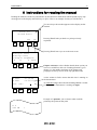
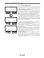
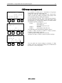
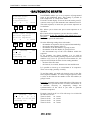
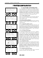
6 Instructions for reading the manual
Reading the manual is made easy and intuitive by the numerous illustrations which explain step by step
what appears on the display and which keys to press. Here is an example of what you will find in it.
You are always shown what appears on the display at that
moment
Clear all
Stored data?
Yes
1
2
4
No
3
A:Single start
B:Group start
C:Simple stopwatch
A
B
C more
5
6
8
1.1
1.2
1.3
7
P 0002
12.14.54
A 0001
00.53:123
Ins. num:
0
9
10
12
Pressing F4 will take you back to a point previously
explained
Pressing F3 will move you on to the next screen
Chapter reference: to have further details about a point you
can access with F3 (in this case ‘Rankings Printout’) go to
chapter 1.3 (the number and name of the chapter and
paragraph are always shown at the top right-hand side)
A time written in Italics means that this time is running on
the chronometer
An underlined digit shows that the blinking cursor is in that
position and the chronometer is waiting for input
11
Example of a printout: you are shown what would be
printed by the printer at that point
N 4
STO TM
1
RACETIME 2
40
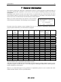
7 General information
The software of Microgate’s Racetime 2 Chronometer consists of various programs for different modes of
functioning which make it possible to use the device for most sports, both during training and in official
competitions.
Depending on the software version in your possession, it is possible that some of the functions described
in this manual cannot be used with your system. At the beginning of each chapter, the program versions
which can be used for the function to be described are clearly indicated.
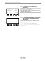
When you switch on Racetime2, the software version installed
will be shown on the display. The following screen will appear:
Microgate - Italy
RACETIME 2 – Vx.y.zz
SN ########
CH. ### (s#######)
From the code of the software version installed (Vx.y.zz), it is possible to immediately determine the
program options with which your chronometer is equipped.
Version
Single
Start +
Simple
Stopwatch
1.x.yy.
2.x.yy
3.x.yy
4.x.yy.
5.x.yy
6.x.yy
7.x.yy
8.x.yy
9.x.yy
10.x.yy
11.x.yy
12.x.yy
13.x.yy
14.x.yy
15.x.yy
16.x.yy
17.x.yy
18.x.yy
19.x.yy
20.x.yy
21.x.yy.
22.x.yy
23.x.yy
24.x.yy
ˇ
ˇ
ˇ
ˇ
ˇ
ˇ
ˇ
ˇ
ˇ
ˇ
ˇ
ˇ
ˇ
ˇ
ˇ
ˇ
ˇ
ˇ
ˇ
ˇ
ˇ
ˇ
ˇ
Test
material
Group
Start
Parallel
PC OnLine
ˇ
ˇ
ˇ
ˇ
ˇ
ˇ
Show
Jumping
Not
Optojump
Microgate
Boards
control
ˇ
ˇ
ˇ
ˇ
ˇ
ˇ
ˇ
ˇ
ˇ
ˇ
ˇ
ˇ
ˇ
ˇ
ˇ
ˇ
ˇ
ˇ
ˇ
ˇ
ˇ
ˇ
ˇ
ˇ
ˇ
ˇ
ˇ
ˇ
ˇ
ˇ
ˇ
ˇ
ˇ
ˇ
ˇ
ˇ
ˇ
ˇ
ˇ
ˇ
ˇ
ˇ
ˇ
ˇ
ˇ
ˇ
ˇ
ˇ
ˇ
ˇ
ˇ
ˇ
ˇ
ˇ
ˇ
The two numbers after (y.zz) indicate your software version.
After that, you will see indicated the serial number of your Racetime2 and the channel currently set for
reception of signals via radio (see par. C.10.1.9 and chapter B - Microgate LINKGATE’s radio system for
further information on the subject).
Note: if you contact Microgate for any problems or explanations, please be sure to indicate the serial
number and the software version of your Racetime2.
RACETIME 2
41
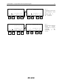
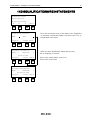
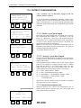
7.1 FUNCTION AND CE KEY USE
The four function keys (F1, F2, F3 and F4) enable the user to ‘converse’ with the machine. All the
operational choices are shown on the bottom line of the display (menu line). To select the option you
want, just press the corresponding function key. If an arrow appears at the beginning or end of the menu
line, this means that a second group of setting options is available. You can go to them with CE.
If you hold down the CE key for more than 0.6 seconds, the printer paper will move forward (provided
your printer is connected - see par. 10.1.11).
S
1 10:07:22.123
Press the key CE to
change the menu line
P
1 10:07:22.123
A
00:00
←lapN ResSk As1 menu
F
00:00
StaN StoN Ask0 SkM→
C
17
18
20
19
16
15
13
14
7.2 NUMERICAL DATA INPUT
It will often be necessary to insert numerical data (for example, an athlete’s start number) with the
numeric keyboard. This possibility is indicated by a blinking cursor on the relevant field.
After indicating the number you want, you can confirm it by pressing ENT (Enter). If any options are
available on the menu line, you can quit the input data phase by pressing one of the active function keys.
In this case the number inserted will be used as input data for the operation you have chosen, as will be
clear in chapter C.3 (‘Timing’).
S
1 10:07:22.123
F
0
Ent.skip N. (0=end)
21 22
24 23
Blinking cursor (shown underlined in the rest
of the manual)
RACETIME 2
42
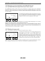
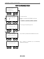
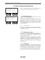
7.3 SWITCHING ON THE MACHINE
Microgate – Italy
RACETIME 2 – Vx.y.zz
SN ########
CH. ### (s#######)
29
30
32
After switching on the machine, you will see the screen
display previously described. Press a key to proceed. At this
point one of the following screens will appear:
31
This message appears if the device completely emptied itself
after the last work session. Any data previously stored has
been irretrievably lost. Press ENTER to continue.
Memory corrupted
Press ENTER
25
26
28
27
This message appears if something has gone wrong during
the initial tests on the machine. Contact Microgate for
further information.
System halted
Call MICROGATE
33
34
36
35
This message normally appears when you switch on. Press
F3 to cancel the timing data previously stored (you must
confirm your choice).
Clear all
Stored data?
37
38
Si
No
40
39
A:Single start
B:Group start
C:Simple stopwatch
A
B
C more
41
42
44
43
A:Parallel mode
B:PC ON-LINE mode
C:OptoJump
A
B
C menu
45
46
48
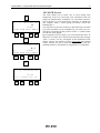
47
It is possible to choose the function mode only if stored data
has been erased.
The following screen will appear.
By pressing F4 (other) you can access other function modes.
Press F4 (menu) to return to the previous screen. With the
function keys, select the required function mode (the
following chapters provide a detailed description of the
various operational modes).
RACETIME 2
NOTES
43
SINGLE START AND
GROUP START
PROGRAM
RACETIME 2 – Single Start and Group Start Program
45
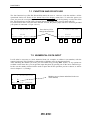
8 Single Start and Group Start Modes
These two function modes will allow you to time very easily the great majority of sporting events, from
alpine skiing to cross-country skiing, from various types of ‘in line’ start competitions to those races
with ‘mass’ starts.
The difference between the ‘single’ and ‘group’ start forms is the way in which the numbers which appear
on the Racetime2 starting line are considered.
In the first case (Single starts) both start and finish numbers refer to the single athlete (or single team).
Consequently, for each start there will be one finish. In group starts, on the other hand, the start numbers
refer to a group of competitors who will have to start at the same time. However, the finish numbers will
refer to single athletes and net times will be calculated according to the group the athletes belong to.
When you have chosen a function mode, the following screen will appear:
Clear all
Config data?
Yes
57
58
60
No
If your answer is ‘YES’ (F3, a second confirmation is then
necessary), it will be possible to configure the parameters
automatically so as to set the chronometer for the type of
timing you wish to make. In particular, the following choices
will appear:
59
A:Training setup
B:Alpin Ski setup
c:Nordic Ski setup
A
B
C more
49
50
52
51
A:Generic timing
A
53
more
54
56
55
The following configuration parameter settings correspond to each of the various options (for a complete
description of the meaning of each parameter, see chap. C.10):
Training Configuration
Automatic finish search: enabled
Automatic assigning of net times: activated
Maximum time: 3 minutes
Display of net times: single run times
Printout of event times: disactivated
Net time print mode: print after finish
Measurement accuracy: 1/100s
Input deactivation time (‘dead times’): Start 2s, Lap 0.5s, Stop 0.5s
Unit of speed measurement: km/hr
RACETIME 2 – Single Start and Group Start Program
Alpine Skiing Configuration
Automatic finish search: enabled
Automatic assigning of net times: disactivated
Maximum time: 3 minutes
Display of net times : total times
Printout of event times: disactivated
Net time print mode: print after finish
Measurement accuracy: 1/100s
Input disactivation time (‘dead times’): Start 2s, Lap 0.5s, Stop 0.5s
Unit of speed measurement: km/hr
Cross-Country Skiing Configuration
Automatic finish search: disabled
Automatic assigning of net times: disactivated
Maximum time: unlimited
Display of net times: single run times
Printout of event times: disactivated
Net time print mode: print after every event
Measurement accuracy: 1/10s
Input disactivation time (‘dead times’): Start 2s, Lap 0.5s, Stop 0.5s
Unit of speed measurement: km/hr
Generic Timing Configuration
Automatic finish search: disabled
Automatic assigning of net times: disactivated
Maximum time: unlimited
Display of net times : single run times
Printout of event times: disactivated
Net time print mode: print after every event
Measurement accuracy: 1/100s
Input disactivation time (‘dead times’): Start 2s, Lap 0.5s, Stop 0.5s
Unit of speed measurement: km/hr
46
RACETIME 2 – Single Start and Group Start Program
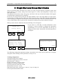
9 Main Menus
A:Timing program
B:Ent./print groups
C:Printouts/Rankings
A
B
C more
61
62
64
3
4
5
A:Autom.start
B:Dispualif.
C:Synchronize
A
B
C
65
66
68
6
7
8
63
more
9
70
72
11.3
11.4
10 1
74
76
10.3
10.2
B
77
78
11.5
11.1
menu
80
Select the items with the four function keys:
A. Machine configuration
B. To access displayboard configuration menu
C. To access skitest configuration menu
F4. To show next menu
75
A:Time calculator
B:Battery charge
A
Select the items with the four function keys:
A. Data transmission to PC
B. To receive data from LINKGATE module
C. Radio signal quality test (Linkgate system)
F4. To show next menu
71
A:RACETIME config.
B:Disp.Board conf.
C:Skitest config.
A
B
C more
73
Select the items with the four function keys:
A. Automatic start management
B. Disqualifications management
C. To synchronize the internal clock
F4. To show next menu
67
A:Send stored data
B:LINKGATE download
C:Signal level
A
B
C more
69
Select the items with the four function keys:
A. To enter timing mode
B. To enter the group management and printout submenu
C. To enter rankings
F4. To show next menu
79
Select the items with the four function keys:
A. To access time calculation function
B. To access battery charge function
F4. To main menu
47
RACETIME 2 – Single Start and Group Start Program
48
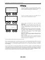
10Timing
A:Timing program
B:Ent./print groups
C:Printouts/Rankings
A
B
C more
85
86
88
Press F1 for timing; to get to know the machine, practice
with the manual keys START-STOP-LAP, which will
then be replaced by starting gates and photocells.
87
Set the run number (usually the last number used is
shown), which will immediately be printed.
Wich run?
81
S
82
1
__
84
83
10:07:22.123
F
00:00
StaN StoN Ask0 SkM→
89
90
92
91
During timing, the display lines show the following
information:
Line 1: This is for the start and shows the number of the
athlete starting and the current time (which can be set by
selecting ‘Synchronization’ from the main menu - see
chap.C8).
Line 2: Normally empty, it is used to set the lap number,
to display speeds transmitted from the Microgate
LINKGATE system and to show the number of events
(starts, laps and finishes) in the events memory
(maximum 64 times).
Line 3: It is used to show net times either for finish or
laps and to insert the start numbers of athletes at the
finish or for laps.
Line 4: Normally offers a menu of operational choices
which can be activated with the function keys; sometimes
messages for the user are displayed.
The start number automatically increases after each start.
If the ‘automatic finish search’ is activated, (see par. C10.1.3), at the finishing line the number of the first
athlete to start from among the numbers of athletes still in the race will be shown. However, it is possible
to use the keys ↑-↓ to run through the athletes still in the race or to set directly the number of the athlete
who is finishing.
As you will be able to see from the following notes, Racetime2’s software is extremely flexible and
makes possible all types of modifications and/or corrections. It is important to note that every operation
can be made with the necessary calm as all the events which take place while you are making a correction
or modification are automatically memorized in a ‘buffer memory’ which is capable of holding 64 events.
These are then presented to the user in the same sequence in which they took place.
RACETIME 2 – Single Start and Group Start Program
49
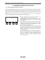
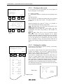
10.1 INSERTION/CORRECTION FUNCTION
10.1.1 Start number insertion/correction
Select Nsta (Start Number) with the F1 key. Use the numeric keyboard to set the number. (Once again it
must be remembered that if group function mode has been set, this number refers to the group and not to
the single athlete). Then with ENTER confirm the number, which will be the next number to start. If this
number has already started, the anomaly will be signalled and it will be possible to cancel the previous
start.
You can also confirm the setting by pressing one of the function keys F1, F2, F3 or F4 (Cle Repl Eevt
NS) instead of ENTER. In this case you will obtain the following results:
S
_
F
Cle
Repl
93
94
10:07:22.123
Eevt
96
NS
95
F1 (Cle - Clear): cancels the start time set - however, you
are asked to confirm before cancellation takes place
F2 (Repl- Replace): assigns the event time for the number
set to another number which must be subsequently inserted
in the fourth line
If the number to which the event time is to be assigned (the
second number set) has already been used you can choose
whether to cancel the previous event time (Cle - F2 key),
switch the two event times around (Repl -F3 key) or leave
the stored data unchanged (Esca - F4).
F3 (Eevt – Edit event time): makes it possible to modify
the start time of the set number. This option also enables you
to insert starts ‘manually’. All you need to do is simulate the
athlete’s start by activating the start key on the keyboard and
then change the time
F4 (NS – Non starters): inserts the number assigned in the
list of non-starters and prints the event time with the code
‘NS’. The ‘non-starters’ can then be printed (par. C5.4).
However, it is possible to ‘restart’ an athlete previously
marked ‘NS’ simply by calling him up again and canceling
the previous operation.
RACETIME 2 – Single Start and Group Start Program
50
10.1.2 Finish number insertion/correction
P
1 10:07:22.123
A
00:00
StaN StoN Ask0 SkM→
97
98
100
99
S
2
F
Cle
_ 10:04:12.123
Repl
Eevt NS
101
102
10:07:22.123
104
103
Select StoN (Stop Number) with the key F2. Use the
numeric keyboard to set the number. The number always
refers to the start number of the single athlete even if you are
working in ‘Group start’ mode. Then with ENTER confirm
the number, which will be the next number to finish or to
pass an intermediate time point. If this number (or the group
which it is in) has already started, the net running time will
appear on the screen display and displayboard. If the number
has not yet started, running time will be shown only after the
start.
You can also confirm the setting by pressing one of the
function keys F1, F2, F3 or F4 (Cle Repl Eevt NS) instead of
ENTER. In this case you will obtain the following results:
F1 (Cle - Clear): cancels the set finish time - however, you
are asked to confirm before cancelation takes place
F2 (Repl - Replace): assigns the event time for the number
set to another number which must be subsequently inserted
in the fourth line. It also calculates the net times of the new
number to which the event time is assigned If the number to
which the event time is to be assigned (the second number
set) has already been used you can choose whether to cancel
the previous event time (Cle - F2 key), switch the two event
times around (Repl -F3 key) or leave the stored data
unchanged (Esca - F4).
F3 (Eevt – Edit event time): makes it possible to modify
the finish time of the set number.
F4 (NS - Non finishers): inserts the number assigned in the
list of non-finishers and prints the event time with the code
‘NS’; at the same time the number is removed from the list
of athletes in the race. The ‘non-finishers’ can then be
printed (par. C5.4). However, it is possible to reinstate an
athlete previously marked ‘NS’ simply by calling him up
again and canceling the previous operation.
10.1.3 Use of keys ↑ ↓
On the display the ↑ and ↓ keys allow you to run through
the athletes on the track at that moment. Press ↑ to view the
athlete who started before the one currently shown on the
display; press ↓ to view the athlete who started after.
RACETIME 2 – Single Start and Group Start Program
51
10.1.4 Turning the Autoskip function on and
off
S
1
10:07:22.123
F
10:04:12.123
StaN StoN Ask0 SkM→
109
S
110
2
112
111
10:07:22.123
The Automatic Skip function (that is, the automatic
assignment of a consecutive number to all lap or finish
timings and temporary memorisation for later assignment to
a start number) can be turned on or off using the F3
(ASk0/ASk1) key. On the display the current status of the
function is indicated: Ask0 means that the function is OFF
and Ask1 means that it is on. See also paragraphs C1.4, C1.6
and C3.3 for further information about the Skip function.
Note: You cannot use the Autoskip function if the printer is
not connected
F
10:04:12.123
StaN StoN Ask1 SkM→
105
106
108
107
10.1.5 Skipped management (SkM)
S
2
10:07:22.123
F
0
Ent.skip N. (0=end)
113
S
114
1
116
115
10:07:22.123
F
0 10:05:12.543
Ins. Start number
117
118
120
119
This enables you to assign numbers after an interval of time
to events previously ‘skipped’ with the ‘skip’ function. To
access this function, press F4 (Gsk) from the timing menu.
Insert the skip identification number and then the start
number to which it must be assigned.
If such an event has already been assigned to the start
number indicated (e.g. two finishes for the same start
number), the anomaly is signalled and you can cancel the
previous event.
To assign the same ‘skipped’ event to more than one
number, you need only to recall the relevant skipped number
and repeat the procedure. In this case, the message ‘Already
assigned’ will appear on the display.
RACETIME 2 – Single Start and Group Start Program
52
10.1.6 Editing or displaying intermediate times
S
1
10:07:22.123
F
00:00
LapN ResSk As0 menu
121
S
Lap
F
Cle
122
123
2 10:07:22.123
N
1
_ 10:04:12.123
Repl
Eevt
125
126
S
2
F
124
128
127
10:07:22.123
_ 10:04:12.123
Sure?
Yes No
130
129
P
1
132
131
10:07:22.123
A
00:00
LapN ResSk As1 menu
133
134
136
135
Choose LapN (Lap Number) by pressing F1 from the
SECOND screen display of the timing menu. (Remember
that to access the second screen display you must press the
key CE - see also par. C.2.1). Set the intermediate time
number on the second line and then the start number on the
third line. This number always refers to the start number of
the single racer, even if the ‘Group Start’ mode has been set.
Now with ENTER, the intermediate time for the selected
start number and intermediate stage number will be
displayed. You can return to the previous screen by pressing
the ENTER key a second time. This operation has no effect
on stored data.
Instead of using the ENTER key, it is also possible to
confirm the setting by pressing one of the function keys F1,
F2 or F3 (Cle Repl Eevt). In this case, you will obtain the
following results:
F1 (Cle - Clear): cancels the set finish time - however, you
are asked to confirm before cancelation takes place.
F2 (Repl- Replace): assigns the event time for the number
set to another number and/or another intermediate time
number. The start and intermediate time numbers to which
the event time is to be assigned should then be inserted
following the instructions in the fourth line of the display.
This function also calculates the net times of the new
number to which the event time is assigned. If the number to
which the event time is to be assigned (the second number
set) has already been used you can choose whether to cancel
the previous event time (Cle - F2 key), switch the two event
times around (Repl -F3 key) or leave the stored data
unchanged (Esca - F4). F3 (Eevt - Edit event time): makes it
possible to modify the intermediate time of the set number.
10.1.7 Cancelling Skipped events memory.
Skipped events which have not yet been assigned can be
canceled in a block by pressing the F2 key from the
SECOND screen of the timing menu. Cancellation is
irreversible and must therefore be confirmed before it is
carried out.
10.1.8 Activation/disactivation of automatic
assignment of finishes and intermediate
times on and off
When the function for automatic assignment of finishes and
intermediate times is on, the net time calculated when there
is an intermediate time or finish is automatically assigned to
the athlete and memorised 5 seconds after the timing is
taken. This only takes place if the racer was already ‘on line’
(that is, if the net time was running) before the event. Even if
no athletes were ‘on line’, manual assignment and
confirmation are still necessary.
RACETIME 2 – Single Start and Group Start Program
53
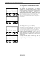
The current status of the automatic assignment function is indicated by the symbols ‘AS1’ (on) and ‘AS0’
(off). Key F3 ( on the SECOND screen of the timing menu) enables you to turn the function on and off.
10.1.9 Returning to the main menu
S
1
10:07:22.123
To return to the main menu, press CE to go to the second
line of the menu and then press F4.
F
00:00
LapN ResSk As0 menu
137
138
140
139
10.1.10 Returning to the main menu during
timing
Clear all
Config data?
141
142
Si
No
144
143
It is possible to return to the main menu and so reconfigure
the device, make printouts or prepare rankings even when
one or two athletes are on the track. Any Start-Stop-Lap
signals that arrive while RACETIME is not set to the timing
function and while some athletes are still on the track, are
memorised. In this case, when you return to the timing
function, the following display appears:
Select Yes (F3) if you do not wish to process the events
and No (F4) if you do.
RACETIME 2 – Single Start and Group Start Program
54
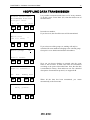
10.2 MANAGEMENT OF EVENTS
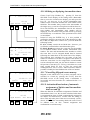
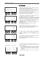
10.2.1 Displaying starts
S
3* 10:07:22.123
F
StaN StoN
145
P
146
1
A
Cle
149
00:00
Ask0 SkM→
148
147
10:07:22.123
When a start takes place (single or group), the time of day
shown on the first line of the chronometer stops for 5
seconds, indicating the starting time. At the same time, an
asterisk blinks between the number of the starting
competitor/group and the time. If ‘print event times’ and
the printer are activated, the time is printed out. During these
5 seconds, it is not possible to correct the starting number
In particular, by setting a number different from the one
presented and confirming with ENTER the start is assigned
to the number set.
00:00
NS
150
152
Simply by pressing ENTER (without changing the
competitor number) the start of the number presented is
confirmed.
151
It is also possible to annul the event with F1 (Ann) (if the
START impulse was accidental) or declare the competitor to
be a Non Starter by pressing F4 (NP). When the competitor
is declared NP, the start time is automatically assigned to the
next competitor due to start.
The start event can in any case be corrected later (see the
paragraph on this subject).
If automatic assignment of finishes is disabled and there are
a number of events that have accumulated in the memory,
Racetime 2 automatically enters the correction mode
described above when the START events must be managed.
RACETIME 2 – Single Start and Group Start Program
55
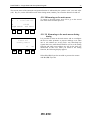
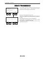
10.2.2 Finishes management
S
1
10:07:22.123
F
00:00
StaN StoN Ask0 SkM→
153
154
156
155
STO
S
2
10:07:22.123
F
12
Cle. Skip
157
158
34.567
Eevt S.T.
160
159
fig. A
P
2
10:07:22.123
A
0 10:06:21.547
Cle. Skip Eevt S.T
161
fig. B
162
164
163
If a finish number has been set (with the chronometer showing
net running time on line 3), when a stop signal arrives (whether
manual, from input or via radio) the net time in relation to the
number previously set is shown (fig. A).
However, if no number has been set (stop line on 00.00 or with
the finish or intermediate time of the previous number, or net
time for a group still running - this last case being identifiable by
the presence of the letter ‘G’ on the third line on the left of the
display ), the event time for the finish will be shown (fig.B).
In both cases you are asked to insert a start number. The time of
the number indicated or previously displayed can be confirmed
by pressing ENTER. Important: the assignment of the time to the
number displayed takes place automatically if the function for
automatic assignment of net times is on (see par. C3.1.8). If the
number has already finished, this is signalled and it is then
possible to cancel the previous finish.
You can also confirm the setting by pressing one of the function
keys F1, F2, F3 or F4 (Cle Repl Eevt NS) instead of ENTER. In
this case you will obtain the following results:
F1 (Cle – Clear): cancels the event. This is the option to choose
if the stop impulse was accidental (e.g. unintentional crossing of
the finishing line) – however confirmation is requested before
cancelation takes place.
F2 (Skip): assigns the time measured to a unique identification
number. In this way it is possible to manage a rapid sequence of
finishes extremely efficiently, leaving the matching up of finishes
with start numbers for later (see par. C3.1.5.)
F3 (Eevt – Edit event time): makes it possible to modify the
finish times measured.
F4 (ST – Same Time): allows you to assign the same time to
more than one start number. It is particularly useful for group
finishes. All the start numbers which have to be assigned a finish
can be set later. Once again, use S.T. to confirm. To finish the
sequence, press ENTER.
RACETIME 2 – Single Start and Group Start Program
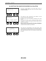
S
2
10:07:22.123
F
5 10:06:21.547
Cle. Skip Eevt S.T.
165
166
S
2
168
S
56
2
10:07:22.123
F
7 10:06:21.547
Cle. Skip Eevt S.T.
167
170
169
172
Fig. C
Assignment of the same
time to athletes n. 5 and
7:
Press 5 – F4 – 7 –
F4 – ENTER
171
fig. D
10:07:22.123
F
5 10:06:21.547
Already used number
173
174
176
175
S
2
10:07:22.123
F
5 10:06:21.547
Cle.pre.?
Yes No
177
178
180
179
If a previously used start
number is inserted,
confirmation is always
requested
for
overwriting
in
the
memory
RACETIME 2 – Single Start and Group Start Program
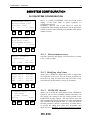
10.2.3
S
1
10:07:22.123
F
00:00
StaN StoN Ask0 SkM→
181
182
184
183
LAP
S
2 10:07:22.123
L. 1
F
12
34.567
Cle. Skip Nlap ST→
185
186
188
187
fig. A
CE
S
2 10:07:22.123
L. 1
34.567
F
12
←Eevt
189
190
192
191
fig. B
S
2 10:07:22.123
L. 1
F
0 10:06:21.547
Cle. Skip
Nlap
193
fig. C
194
196
195
57
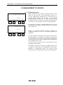
Intermediate time management
If a finish number has been set (with the chronometer
showing net running time on line 3), on the arrival of an
intermediate time signal the net time for the number
previously set is displayed. If the impulse has been
generated manually or received via cable from the LAP
input, the consecutive intermediate number will
automatically be calculated on the basis of the intermediate
times previously taken for that particular number
If, on the other hand, the intermediate time signal has been
received via radio, the intermediate number corresponds to
the one set on the LINKGATE Encoder. In this case
Racetime automatically manages the correct sequence of
intermediate times, even if several athletes are on the
racetrack at the same time. An example may help to clarify
this concept: suppose we are timing a race with two
intermediate times. The first athlete starts and completes the
first intermediate time. Then a second athlete starts and
completes the first intermediate time before starter 1
completes the second intermediate time. In this case,
Racetime will attribute the first intermediate time signal ‘1’
to the first athlete and when the second intermediate time
signal ‘1’ arrives, it will be automatically assigned to the
second athlete without the need for any type of action on the
chronometer.
Note: Lap 14 (Lap E on the Linkgate Encoder) is managed
by Racetime 2 in the same way as an impulse received from
the keyboard or an input. Therefore the intermediate number
will not be ‘14’, but will be calculated automatically on the
basis of the previously taken intermediate times. In this way
Linkgate Encoder can be used for the transmission of the
intermediate time.
The insertion of the start number is requested (or the
confirmation of the number already displayed).
Important: The assignment of a time to the number
displayed can only operate automatically if the function for
automatic assignment of net times is on (see par. C3.1.8). If
another intermediate time already corresponds to the
confirmed starting number and intermediate number of an
athlete, a warning will be signalled and you will be able to
cancel the previous event.
RACETIME 2 – Single Start and Group Start Program
58
10.2.4 Displaying speeds transmitted by the LINKGATE Encoder
(note: only available on Racetime2 equipped with the optional ‘Skitest’ software)
The LINKGATE Encoder systems used for the transmission of timing signals (start, intermediate
time/times or finish) can also be set to transmit passing speed (for installation instructions, see par. B3.5).
In this case, when a timing impulse is received via radio, passing speed data will appear on the second
line of the display.
S
2 10:07:22.123
L. 1
58.64Kmh
F
12
34.567
Cle. Skip Nlap ST→
197
198
200
If a length for the speed base used was previously set (see par.
C10.2.1), speed will be immediately displayed in the selected
unit of measurement (see par. C10.2.3). However, if the base
length has not been set, base running time will be shown.
199
NOTE 1 : Racetime2 only memorises running time so it is always possible subsequently to set or modify
both the measurement length base and the speed measurement unit.
NOTE 2: The speed base times are displayed with an accuracy of one thousandth of a second. However
the acquisition, transmission and memorisation of these times are performed with much higher precision
(approximately 1/8000s), which is sufficient to guarantee excellent accuracy in speed measurement even
with measurement bases of limited length (3-5 meters).
10.2.5 Display of average speeds
(Note : only available on Racetime 2 fitted with the optional software ‘Skitest’)
S
2 10:07:22.123
L. 1
AV 45.14Kmh
F
12
34.567
Cle. Skip Nlap ST→
201
202
204
If a distance has already been set for average speeds, that is, the
total length of the course or the length between two
intermediate points (see par. C10.2.2 on the subject of the
setting of ‘average speeds’), the average speed is shown directly
in the preselected unit of measurement (see par. C.10.2.3). The
letters 'VM' to the left of the speed make it possible to
distinguish this speed from that of the radio-transmitted speed.
203
Note : if the average speed and the instant (radio-transmitted) speed are acquired simultaneously, only the
latter is displayed. Obviously, however, both items of information are printed and memorised.
RACETIME 2 – Single Start and Group Start Program
59
10.2.6 LCK key use
LCK
S
10:07:22.123
#
F
00:00
StaN StoN Ask0 SkM→
205
1
206
208
207
STO
S
10:09:42.123
# 1
F
00:00
StaN StoN Ask0 SkM→
209
1
210
212
211
LCK
S
1
F
10:09:42.123
00:00
Cle. 1 events Yes
213
214
216
No
215
The LCK allows you to block one or more timing lines
temporarily. Even if, as previously seen, unwanted events can
always be annulled later, sometimes it is convenient to block a
line in advance to avoid an annoying sequence of annulments
(for example, when a whole group of tourists crosses the
finishing line...).
You only have to press the LCK key to block the lines on which
it is active and these can be configured as you want (see par.).
The block is indicated by the presence of the ‘#’ symbol on the
second line of the display.
By pressing the LCK key again, you can reactivate the lines. At
this point, if at least one event has been discarded, the message
‘Canc. x eventi ? Yes No’ will appear on the fourth line of the
display. Answer Yes with F3 to cancel irreversibly the acquired
events. Answer No (F4) to deal with the events one by one,
deciding whether to annul them or assign them to a competitor.
RACETIME 2 – Single Start and Group Start Program
60
11INTERPRETATION OF PRINTED DATA DURING
TIMING
The removable printer on your Racetime allows you to print event times, net times and speeds during
timing. The printing mode depends on the setting of two configurations, which are accessible under the
menu heading ‘Config. RACETIME’.
In particular, the printing of event times (that is, the time of day at which the various events -Start- LapStop take place) can be activated/disactivated by intervening on the relevant configuration (see par.
C10.1.2 on this subject).
With regard to net times, depending on the setting of the ‘net times print mode’ (see par. C10.1.4) these
can be printed after every event (that is, after every lap time or finish) or a synoptic printout can be made,
but only after the athlete has finished.
Event times, together with the information that is needed to characterize them, are printed in the
following format:
CR
3
STm
Operation
identifier
Start number Event time type
serial for
and id. source
skipped
12:23:45.678
Time (HH:MM:SS.dcm)
The operation identifier (2 characters) shows which operation is coupled with the event time, that is:
ET
event time printout for normal event acquisition
CA
event time cancelation
SK
event time skip - in this case, instead of the start number the unique
consecutive identification number is printed
EE
event time editing
RE
replacement (printed together with cancelation when an event time start
number is replaced)
The event time type (2 characters) shows if the event time is coupled with a start, intermediate time or
finish:
ST
start time (start)
SP
finish time (stop)
LP
intermediate time (lap)
The source identifier (1 character) shows how the event time has been acquired:
m
manually (with the Start - Lap – Stop keys)
r
received via radio
k
manually edited (with event time edit option - Eevt)
a
automatically generated (only for automatic pre – programmed starts)
e
acquired subsequently through download of event times from Linkgate (see
cap. C11.3)
The time is always shown with all the digits (even if zeros) and with an accuracy of 1/1000s,
with approximation by truncation (remember that RACETIME acquires all times with an
accuracy of 1/25000s)
CR 4
SK 3
AN 5
SPm 11:19:10.985
SPi 11:20:46.945
STm 11:13:28.432
RACETIME 2 – Single Start and Group Start Program
61
Net times together with the information that is needed to characterize them are printed in the following
format:
SPT
1:15.28
Identifier of net time type
(first two letters) and
total/single run identifier
Net time (HH:MM:SS.dcm)
or
L4
58.16
Intermediate (LAP)
With progressive
Intermediate number
The identifier of net time type shows if it is a finish time (SP - STOP) or an intermediate time (SL SPLIT or L - LAP according to whether the time is a partial time calculated from the start or from the
previous intermediate time).
The consecutive intermediate number appears only for LAP times.
The total/single run identifier shows if the time is the total of run times (T) or only a single run time (M).
The time is printed only with significant digits and with a number of decimal digits which depends on the
selected accuracy of measurement (see par. C10.1.6).
Notice that for the first intermediate event, the LAP time is not printed because it is the same as the
SPLIT time. For subsequent laps, SPLIT and LAP times are always printed one after the other. In this
way the intermediate time displayed is immediately recognizable by the number which is shown together
with the LAP time.
The speed or speed base times are printed in the following format:
V=138.25km/h
For printing of speed (only if the length for the base being considered has been set)
or
Tv=0.234s
If the running time of the base is printed without its length
Printing immediately follows the net time calculated in relation to the speed measurement base.
The average speed is printed in the following format:
VM=123.45km/h
RACETIME 2 – Single Start and Group Start Program
62
12Group management
216.1.1..1
A:Ent
./edit groups
B:Clear groups
c:Print groups
217
Group
218
N.
220
219
1
fr.
to
(0 to end input)
221
222
224
223
It is possible to define up to a maximum of 98 groups,
subdivided in turn into 8 subgroups each.
Groups are used both when working in the ‘Group starts’
mode, to define the numbers assigned to the groups at the
start, and when printing rankings by category.
For the definition of groups, select ‘B:Ins./group printouts’
from the main menu (F2) and then ‘A:Ins./edit groups’ from
the submenu (F1). At this point, suppose you wish to define
the following groups (categories):
Group 1
start numbers 1 to 10
start number 15
start number from 20 to 28
Group 2
not used
Group 3
start numbers from 40 to 50
You must then press the following sequence of keys:
1, Enter, 1, Enter, 10, Enter, 15, Enter, 15, Enter, 20, Enter,
28, Enter, 0, Enter (end of group 1)
3, Enter (group 3 setting, group 2 is not used)
40, Enter, 50, Enter, 0, Enter, 0, Enter (to quit the setting).
Group N.
1
Choice N.
3
fr. 20
to
28
(0 to input)
225
226
228
227
You can check the correct setting by selecting ‘C: Print
groups’ (F3) or by viewing the groups you are interested in
by means of ‘A:Ins./edit groups’.
RACETIME 2 – Single Start and Group Start Program
228.1.1..1
A:Ent
./edit groups
B:Clear groups
c:Print groups
229
230
232
231
232.1.1..1
A:Ent
./edit groups
B:Clear groups
c:Print groups
233
234
236
235
To cancel completely the current setting for groups
select ‘B:Cancel groups’ (F2). To cancel one group
only, insert 0 in choice 1 of the group to be canceled.
63
RACETIME 2 – Single Start and Group Start Program
64
Printout and rankings management
A:Timing program
B:Ent./print groups
C:Printouts/Rankings
A
B
C more
240
239
237
238
A:Ranking,stop time
B:Ranking,interm.
C:Ranking,speed
A
B
C more
257
258
260
259
A:Eventtimes
B:NS/NA/Disqual.
C:Skipped
A
B
C menu
253
254
256
B
249
250
12.1 RANKINGS FOR FINISH TIMES,
INTERMEDIATE TIMES AND SPEED
From the menu it is possible to choose from rankings
calculated on the basis of total or single run finish times,
intermediate times (split total, split run or split lap), or the
running speed acquired by the LINKGATE Encoder.
By total split time, we mean the run times for runs prior to
the one selected added to the time between the start and the
selected intermediate time.
All the rankings can be limited to a particular group or can
be extended to all the start numbers. (The latter choice can
be selected by inserting 99 in the screen for group settings).
The rankings can be viewed on the display or printed out.
255
A:Total times
B:Run times
A
Racetime 2 is equipped with such powerful management of
rankings that it can almost totally replace the Personal
Computer in subsequent data revision.
To access the rankings menu, press F3 (Rankings printouts)
from the first screen of the main menu.
Total time refers to the sum of the single run times up to the
selected run; it only exists if the athlete has, in fact, the times
of the runs prior to the selected one.
252
251
Enter the chosen run number.
Which run?
245
246
__
248
Wich group?
247
99
If you select a group from those set (see chap. C4), the
ranking will be calculated only on the basis of the start
numbers belonging to the group selected. Group 99 is set as
default and includes all start numbers.
99=all racers
241
242
244
243
RACETIME 2 – Single Start and Group Start Program
65
12.1.1 Viewing on the screen
Data output on:
A:Display
B:Printer
A
B
menu
262
261
N
264
263
7
L1 V=123.45Kmh
28.31 8.15
1:06.247
p. 2
←
→
265
266
find menu
268
267
fig. A
If you choose F1 to view the display, the screen display in
Fig.A will appear. In this display:
N = number of athlete
L = intermediate number to which speed and split/lap times
refer.
split time lap time
time on the basis of which the ranking has been calculated
(total, single run, split, lap or speed – according to choice)
position
With the function keys and the ↑↓ keys, it is possible to
move around inside the ranking. In particular:
←→ (F1- F2): allow you to go from one position in the
ranking to the next or previous one
search (F3): you are asked for a start number and, after
confirmation, the times and position of that number are
displayed
↑ and ↓ keys: allow you to view in succession all the
intermediate times and speeds obtained for an athlete
currently shown in a ranking. Note that the time and position
shown on the third line do not change when you use these
keys as the ranking was calculated on the basis of these
times. In addition, if only a net time has been taken for an
athlete in the ranking, nothing will happen when you press ↓
and ↑.
12.1.2 Printing the ranking
A:Print select.only
B:Complete print
A
B
269
270
menu
272
RANK. T.TOTAL
Manche N.1
Pos 1 Num
2
SLT
15.68
L2
42.77
SLT
58.46
V=
34.60 km/h
L3
34.51
SPT
1:32.97
Pos 2 Num
1
SLT
16.28
L2
42.17
SLT
58.46
V=
30.88 km/h
L3
34.75
SPT
1:33.22
271
If you choose ‘data output on: printer’ (F2 key), a new menu
will be shown on the screen:
If you choose ‘Print selection’ (F1), apart from the athlete’s
position and number, only the times requested from the
options of the rankings menu (for example, only the total
times for the second run) will be printed.
If you choose ‘Complete print’ (F2), on the other hand, you
will get a synoptic printout with all the net times of every
athlete, together with any speeds, ordered according to the
time on the basis of which the ranking has been calculated.
This print mode is particularly useful in training as it makes
it possible to have a complete picture of how the run went.
The following example gives the final positions for the same
run presented in both modes.
RANK. T.TOTAL
Manche N.1
Print select
Complete print
Pos
1
2
Num
2
3
Tempo
1:32.97
1:33.22
RACETIME 2 – Single Start and Group Start Program
A:Ranking,stop time
B:Ranking,interm.
C:Ranking,speed
A
B
C more
281
282
284
more
288
287
Laptime number?
__
289
286
290
12.2 INTERMEDIATE TIME RANKINGS
283
A: SPLIT total
B: SPLIT run
C: LAP
A
B
C
285
292
Total SPLIT time refers to the time taken by the athlete from
the start of the first run to the intermediate time being
considered. Single run SPLIT time refers to the time taken
from the start to the intermediate time of the single run being
considered. LAP refers to the time taken from the start to the
first intermediate time, and from the first intermediate time
to the finish.
It is possible to ask for the ranking of a particular
intermediate time.
291
Enter the single run number chosen
Which run?
293
294
__
296
Which group?
295
If you select one of the set groups, the ranking will be
calculated only for start numbers belonging to the selected
group. Group 99 is set as default and includes all start
numbers.
99
99=all racers
273
274
276
278
275
Press F1 to display an output
Press F2 to print the ranking
Data output:
A:Display
B:Printer
A
B
277
66
menu
280
279
RACETIME 2 – Single Start and Group Start Program
67
12.3 SPEED RANKINGS
A:Ranking,stop time
B:Ranking,interm.
C:Ranking,speed
A
B
C more
297
298
300
299
A:Radio speed
B:Average speed
A
B
301
302
Select ‘A: Radio Speed’ if you want to calculate the
ranking of the speeds transmitted by the Linkgate
system. Select ‘B: Average Speed’ for the ranking of the
average speeds from Start to Stop or from Lap to Lap.
menu
304
303
Laptime number?
_
(0=Start, 15=Stop)
309
310
312
Laptime number? __
(0=Di. Start-Finish)
311
305
Speed ranking can be referred to a particular
intermediate time. Set 0 to obtain the ranking for the
average start-finish speed. The ranking is calculated
only if the distance has been previously set (par.
10.2.2 on page 55).
306
308
307
You can get a ranking for speed measured at a
particular intermediate time (1...14), at the start
(0) or at the finish (15)
Enter the single run number chosen
Which run?
313
314
__
316
315
If you select one of the set groups, the
ranking will be calculated only for start
numbers belonging to the selected group.
Group 99 is set as default and includes all
start numbers.
Which group?
99=all racers
317
Data output on:
A:Display
B:Printer
A
B
menu
321
322
324
323
99
318
Press F1 to display an output
Press F2 to print the ranking
320
319
RACETIME 2 – Software “Cronometro Base”
68
12.4 PRINTING EVENT TIMES, NP, NF,
DISQUALIFIED, SKIPPED
A:Ranking,stop time
B:Ranking,interm.
C:Ranking,speed
A
B
C more
325
326
328
327
A:Eventtimes
B:NS/NA/Disqual.
C: Skipped
A
B
C menu
329
330
332
331
Data output on:
A:Display
B:Printer
A
B
menu
337
338
340
By choosing ‘other’ (F4) from the first page of the rankings
menu, you can access a series of auxiliary printouts.
Printing event times: the event times (that is, the starting
times of the various events) are printed in the order in which
they were acquired. For instructions about each event time,
see par. C1.12
Printing non-starters/non-finishers/disqualifications: nonstarters, non-finishers and those disqualified are shown
divided according to the various runs and with the time at
which they were declared non-starters, non-finishers or in
the case of those disqualified, at the starting time.
Using the ‘NS’ and ‘NF’ functions from the timing menu
(see par. C1.2 and C1.1), you can note that the non-starters
and non-finishers are only the start numbers declared to be
such.
Printing skipped: skipped events not yet assigned to start
numbers are shown together with the event times.
Press F1 for display output
Press F2 for printer output
339
Indicate the run (0 or empty for all runs) and press ENTER
to print.
Which ryn?
(0= all runs)
341
342
344
__
343
When you have finished printing, you will automatically
return to the first menu.
Printing...
333
334
336
335
RACETIME 2 – Software “Cronometro Base”
69
13AUTOMATIC STARTS
A:Autom.start
B:Disqualif.
C:Synchronize
A
B
C
345
346
more
348
347
A:Ent./edit sequence
B:Clear sequence
C:Print sequence
A
B
C menu
349
350
352
N 1
(0=end)
fr. to
st.time
timestep (s)
353
354
351
run
s.
356
355
RACETIME2 enables you to set a sequence of programmed
starts at pre-established times. This setting is possible in
both ‘Single start’ or ‘Group start’ mode.
From the second display screen of the main menu press F1
(Autom. start) to go to the automatic start submenu. Press F1
(Ent./edit sequence) to insert new pre-set start sequences or
to edit them.
F1: Allows you to insert new pre-set start sequences or to
edit them.
F2: Cancels all set sequences (you are asked to confirm)
F3: Printout of only the automatic starts which have yet to
take place
F4: Returns you to the main menu
Now the following settings have to be made:
- the number of sequences (this is proposed automatically)
- the run the start sequence refers to
- the number of the first athlete (or group) to start
- the number of the last athlete (or group) to leave
- the incremental step of the start numbers within the
sequence
If, for example, you choose numbers 1 to 11 with an
increment of 2, the resulting starting sequence will consist of
numbers 1,3,5,7,9,11. If you choose an increment of 1, the
sequence will include all of the eleven starting numbers.
- the time of the first start
- the interval, in seconds, between one start and the next
It is possible to insert up to a maximum of 16 sequences.
These can overlap partially or totally.
To end the setting, you need only insert 0 (zero) in the first
field (sequence number). To cancel a single sequence, insert
0 (zero) in the field for the number of the first athlete (or
group) to start.
Important: automatic starts cannot take place if the times set
in the sequences precede the time set on the chronometer. It
is therefore necessary to temporarily change the
synchronization of the clock if you want to generate
retroactive sequences.
N 1 (0=end) run 1
Fr. 1 to
8 s. 2
st.time 12:00:00.000
timestep (s)
10
357
358
360
359
Example. Start from N°1 to N°8 with step=2 at 12.00 with
an interval of 10 sec.:
Time 12:00:00
no. 1 starts
Time 12:00:10
no. 3 starts
Time 12:00:20
no. 5 starts
Time 12:00:30
no. 7 starts
RACETIME 2 – Software “Cronometro Base”
70
14DISQUALIFICATIONS/REINSTATEMENTS
A:Autom.start
B:Disqualif.
C:Synchronize
A
B
C
361
362
364
Disqualification
Num.
Run
Toggle
365
366
more
363
_
other menu
368
367
Disqualification
Num. 1
Manche
1
qualified
Toggle
other menu
369
370
372
371
Disqualification
Num. 1
Manche
1
diqualified
Toggle
other menu
373
374
Insert the run and the name of the athlete to be disqualified
or reinstated; confirm the numbers with Enter (use F4 to go
straight back to the menu).
376
375
When you have identified the athlete and run, press
F1 to disqualify or reinstate.
F3 to insert another athlete code or run
F4 to return to the menu
RACETIME 2 – Software “Cronometro Base”
71
15SYNCHRONIZATION
A:Autom.start
B:Disqualif.
C:Synchronize
A
B
C
382
381
more
384
383
To set the exact time:
Input daytime
22:31:58.289
Example: to synchronize RACETIME at 10.54 AM
Press:
1 0 ENTER 5 4 ENTER 0 ENTER 0 ENTER
386
385
388
387
To correct press F2, otherwise press F3.
Inserire l’ora
10:54:00.000
Corr.
389
390
OK
menu
392
391
Input daytime
10:54:00.000
START synchronize
393
394
396
Press START to synchronize RACETIME at the set time.
395
After a message of confirmation you are automatically
returned to the first menu.
Synchronized!
377
378
380
379
RACETIME 2 – Software “Cronometro Base”
72
16OFF-LINE DATA TRANSMISSION
A:Send stored data
B:LINKGATE download
C:Signal level
A
B
C more
401
402
404
It is possible to transmit stored times to a PC at any moment.
To do this, select ‘Trans. Data’ (F1) from the third screen of
the main menu.
403
Insert the run number.
If you choose 0, data for all the runs will be transmitted.
Which run?
(0= all runs)
405
406
__
408
Which group?
407
99
If you select one of the groups set, ranking will only be
calculated for start numbers belonging to the selected group.
Group 99 is set as default and includes all numbers.
99=all racers
409
410
412
411
Now you can choose whether to transmit only the event
times or the net times. In both cases times are transmitted
according to the protocol described later. Note that the data
is transmitted in ‘binary’ form and not as text. For a detailed
description of transmission protocol, see Appendix B.
Data to transmit?
RT.
EvT.
413
414
NSNASQ menu
416
415
Wait, please…
397
398
400
399
When all the data has been transmitted, you return
automatically to the first menu.
RACETIME 2 – Software “Cronometro Base”
73
17SYSTEM CONFIGURATION
A:RACETIME config.
B:Disp.Board conf.
C:Skitest config
A
B
C other
417
418
420
419
17.1 RACETIME CONFIGURATION
The configuration menu enables you to modify numerous
settings that affect the way Racetime2 functions. Remember,
however, that if you choose to cancel the configuration when
switching on the machine (see chap. C2.3) or to reset a
configuration and select one more suitable for your timing
session, all of the parameters will be set to values which are
normally the most appropriate in the majority of cases.
17.1.1 Time display mode
A:Displ.mode: Run
B:Print Ev.Time: No
C:Next ar.search Yes
A
B
C other
421
422
424
423
Allows you to choose whether to view total times, single run
times or lap times on the screen display and displayboard.
Choose with the F1 key.
17.1.2 Event times printout
Using the F2 key, you can activate/disactivate the automatic
printing of event times when the various events (Starts – Lap
- Stop) take place.
17.1.3 Automatic finish search
A:Runt. Print mode
B:Maxruntime
C:Time rounding
A
B
C more
425
426
428
427
A:Holdoff times
A:LCK-key setup
B:LINKGATE channel
A
B
C more
429
430
432
431
Max runtime:
0:03:00.000
(00:00:00.000=
control disable)
433
434
436
435
Select rounding
precision
1/
1s
437
1/10s
438
100s
440
If this function is activated, during timing Racetime2 will
automatically show the athletes’ net times on the third line
of the screen after they have started. If it is disactivated, you
should activate the display by calling up a competitor with
the ‘Nsto’ key (F2) or by pressing the ↑ ↓ keys. See also par.
C3.1.2 for further explanations.
17.1.4 Net time print mode
By selecting this function with F1 you access a submenu.
You can choose to print net times after the acquisition of
each event (that is, after every intermediate time and after
the finish), or ‘synoptically’ after the athlete has reached the
finish line. This second choice is particularly convenient for
competitions such as alpine skiing, uphill motor-racing,
downhill mountain-biking and other competitions with
individual starts and short durations while printing after each
event is more convenient in sports such as cross-country
skiing, marathons and road cycling.
17.1.5 Maximum time
With this option, you can insert a maximum single run time
above which the competitor will automatically be expelled
and therefore no longer timed. Note however that it is still
possible to ‘reinstate’ a competitor with times greater than
the maximum simply by modifying the maximum time or by
disactivating the function. To disactivate the maximum
time, set the time at 00:00:00.000
17.1.6 Measurement accuracy
1/
1000s
439
You can select measurement precision only for net times
between one second, 1/10s, 1/100s, and 1/1000s.
RACETIME 2 – Software “Cronometro Base”
74
17.1.7 Modifying ‘dead’ times
A:Holdoff times
A:LCK-key setup
B:LINKGATE channel
A
B
C more
441
442
444
Allows you to modify the disactivation times of inputs after
the acquisition of an event. This can be done separately for
the Start, Lap, Stop and AUX lines (the AUX line is only
used in the PC On-line program, see chap. E in the manual).
443
17.1.8 Activating the LCK key
Start
Stop
Lap
Aux
449
HT
HT
HT
HT
450
= 2000 ms
= 500 ms
= 500 ms
= 500 ms
452
451
SLLLLLLLLLLLLLLS
T123456789ABCDEP
---------------#
Modify ←
→ menu
445
446
448
Choose this option to modify the lines on which the LCK
key is active (see also par. C3.2.6). With the arrows (F2 and
F3), it is possible to move the cursor from one field to
another. With ‘Edit’ (F1) the blocking of the line on which
the cursor is positioned can be activated or disactivated –
beginning from the Start (on the far left), passing through
Laps 1...14, to the finish (on the far right). The presence of
the block is indicated by the # symbol. Note that the lap
times refer to the signals transmitted via radio using the
LINKGATE system. The activation of the block on LAP 14
(E) also block LAP signals coming from the keyboard or the
inputs.
447
17.1.9 LINKGATE channel
LINKGATE chan.:
0
(S0000000)
(1=ON, 0=OFF)
Modify
menu
453
454
456
455
Allows you to modify the LINKGATE system work channel
so you can move to another channel if necessary. On the
display, the setting indication for the ‘dip switch’ located on
the LINKGATE Encoder will appear. The first selector does
not affect channel selection (its function is to select signal
length and is therefore shown with the letter ‘S’). Next, the
status of the other switches is shown (1=switch up, 0=switch
down). To modify the setting press ‘Edit’ (F1). Remember
once again that it is absolutely essential that Racetime2 and
the LINKGATE Encoder are set on the same channel (see
chap. B3).
RACETIME 2 – Software “Cronometro Base”
75
17.1.10 Setting of serial transmission
parameters
A:Baudrate:
B:Format:
A
B
457
458
9600
ASCII
more
460
ATTENTION : this configuration is present only on versions
20.x.yy, 21.x.yy, 22.x.yy and 24.x.yy.
Serial transmission velocity is modified by pressing F1
(1200, 2400, 4800 or 9600 bit/s).
Pressing F2 allows you to choose between binary and ASCII
for the format of transmitted data.The transmission protocols
for the two modes are given in Appendix B.
459
A:Printer
On
B:Keyb.beep
On
C:Initialize Setup
A
B
C menu
17.1.11 Activation/disactivation of the printer
and of acoustic signalling when keys
are pressed
To modify the settings press keys F1 and F2 respectively
17.1.12 Initialization of configuration
461
462
464
463
Press F3 and then confirm to go to the configuration options
menu (par. C0.5)
RACETIME 2 – Software “Cronometro Base”
76
17.2 SKITEST CONFIGURATION
A:RACETIME config.
B:Disp.Board conf.
C:Skitest config
A
B
C other
465
466
468
467
A:Speedbases length
B:Speed unit
C:T/Hum.sensor test
A
B
C menu
469
470
472
471
A:Radio speed
B:Average speed
A
B
481
482
484
483
Speedbase
N. 1 (CE to exit)
Input length (meter)
10.0 (0=no test)
477
478
480
479
(Note: available only on Racetime2 equipped with the
optional ‘Skitest’ software)
To access the Skitest configuration submenu, with F3 select
‘Config. Skitest’ from the third screen display of the main
menu. From this menu, you can modify the parameters that
affect the speed measurement and climate data measurement
functions.
17.2.1 ‘Radio’ speed base length
Insert the speed base lengths that you intend using. Specify
the measurement base number (0 = Start base, 1...14 Lap
bases, 15 = Stop base). Next, key in the length of the base
(first meters, up to a maximum of 65000, then centimeters).
A value of zero indicates that on the base concerned, the
speed does not need to be calculated.
Note: you can also insert a speed base length afterwards as
Racetime2 only memorises base running time. The speed is
calculated at the moment of display.
To quit this function press CE.
17.2.2 ‘Average’ speed base length
Insertion of speed base lengths for taking average speeds. By
average speeds is meant the speed taken to cover the various
stages of the course.
The measurement base number refers to the various stages
timed. If, for example, we suppose that the course is 1000m
long and that there are two intermediate points, the first
200m from the start, the second 500m after the first
intermediate point, the distances will be set as follows:
N. 0 ⇒ start - finish distance, 1000m
N. 1 ⇒ start - intermediate1distance, 200m
N. 2 ⇒ intermediate 1 - intermediate 2 distance, 500m
N. 3 ⇒ intermediate 2 - finish distance, 300m
(=1000-200-500)
Also in this case the distances can be inserted or modified
after the times have been acquired.
17.2.3 Speed measurement unit
With the function keys choose the measurement unit in
which speeds must be shown from, m/s, km/h, mph and
knots (nautical miles per hour).
Select
Speed unit
m/s
km/h
473
474
mph knot
476
475
RACETIME 2 – Software “Cronometro Base”
T. Air
T. Snow
Hum. Snow
485
486
= -1.1 °C
= -3.2 °C
=
78 %
60m menu
488
487
77
17.2.4 Temperature and humidity probe tests
It is possible to view the values for air and snow
temperatures and air humidity if the relevant measurement
probes are connected.
Press F1 to print the values displayed, together with the time
of day
Pressing F2 allows you to set an interval in minutes for
automatic data printing. The maximum value that can be set
is 720 minutes, or 12 hours. Automatic printing continues at
regular intervals until you quit the function or until the time
interval is set to zero.
To quit the function, press F4.
When the probes are not connected, Racetime2 shows an
error message.
RACETIME 2 – Software “Cronometro Base”
78
17.3 DISPLAYBOARD CONFIGURATION
A:RACETIME config.
B:Disp.Board conf.
C:Skitest config
A
B
C other
489
490
492
Select 'B : Displayboard Config.' from the second display of
the main menu to access displayboard configuration.
491
17.3.1 Displayboard type
A:Type: Microgate
B:Num.of Disp.B.
1
C:Advertising:
Off
A
B
C menu
493
494
496
495
ATTENTION : this configuration is only present on versions
20.x.yy, 21.x.yy, 22.x.yy and 24.x.yy.
Select the type of displayboard you wish to connect to the
chronometer Racetime 2. Remember that for each
displayboard the appropriate connection cable, available
from Microgate, must be used. For the connection of the
Telecron displayboard it is also essential to use the code
$ACC050 interface.
16.3.1.1
PC-ONLINE Output
It is possible to choose the ‘PC-Online’ displayboard type.
In this case, On-line output of data is activated, as explained
in appendix 2.3 on p.110.
17.3.2 Displayboard number
This option is only active if Microgate displayboards are
used. Press F2 to select the number of displayboards (one or
two). If only one displayboard is used, only the time
(running and final) appears.
If you choose to work with two displayboards, a Master
displayboard and a Slave displayboard are required (or
alternatively, a second Master set to display column 9 as first
column – see the Tabmicro manual on this subject). The
competitor number and the time are displayed
simultaneously.
17.3.3 Advertising
If a Microgate displayboard is used, it is possible to activate
the display program (Prog. 1) previously memorised in the
displayboard itself. For further details, see the instructions
for the Microgate µTAB displayboard on this subject.
Pressing F3 will disactivate the display program and restore
the normal function program (Prog. 0) on the displayboard
RACETIME 2 – Software “Cronometro Base”
79
18OTHER FUNCTIONS
18.1 RECHARGING BATTERIES
A:Time calculator
B:Battery charge
A
B
497
498
menu
500
499
Trickle ch.
A:Rep.charge/disch.
A
501
menu
502
504
Status/message
The recharging of Racetime2’s internal batteries is managed
entirely by the microprocessor which controls all of the
chronometer’s functions. Consequently, it has been possible
to implement a recharge control which guarantees maximum
battery efficiency at all times, at the same time prolonging
the chronometer’s operating life.
To recharge the batteries, connect a 12 - 20 Volt DC power
source (normally you will use the AC/DC adapter supplied
in Racetime’s kit) to the appropriate power point (chap. A2).
If the chronometer is off, information on the current status of
the battery recharge management functions will be
immediately shown on the display.
Specifically, the following messages will appear on the first
line of the display:
503
Function description
LED status
Maintenance
the chronometer is supplied by an external
power source and, concurrently, the
batteries’ efficiency is maintained
by a week recharge current
Brief blinking every
four seconds
Discharge
at the beginning of a recharge cycle, the
batteries are completely run down before
being recharged
LED continuosly lit
Recharge
recharge in progress. On the first line of
the display, the time still to go until
the end of recharge is shown
Blinking LED
Discharging...
A:Immediate charge
B:Break process
A
B
menu
505
506
508
507
Charging
7:00:00.
A:Rep.charge/disch.
B:Break process
A
B
menu
509
510
512
If you see the letters ‘Vext. Ins’ blinking on the first line of the
display, this means that the voltage supplied at the
recharge/supply input is insufficient. ATTENTION: when
external power is insufficient, recharging is interrupted and so
cannot be completed correctly and within the time anticipated.
511
If
the
chronometer
is
in
‘Maintenance’,
press
‘A:Rep.charge/disch.’ (F1) to begin a new charge cycle. This
will start the running down of the batteries. The duration of this
discharge phase is variable and depends on how fully the
batteries are charged. (The time needed to discharge can last up
to four hours).
RACETIME 2 – Software “Cronometro Base”
80
After discharging the batteries, Racetime2 will automatically begin to recharge; this takes seven hours.
After recharging, the words ‘End Charge – OK’ indicate that the process has been correctly completed. If,
however, battery malfunction has caused premature interruption of charging, the messages ‘Err. Batteries
– LV’ (insufficient battery voltage) or ‘Err. Batteries –HV’ (battery voltage too high) will appear. During
recharging the time needed to complete the process will appear on the display.
During discharging, it is possible at any time to go straight over to charging by pressing ‘A:
Rep.charge/disch.’ (F1). This will shorten the time needed for recharging. However, you are advised not
to charge the batteries without first discharging them as this could cause a reduction in the capacity of the
batteries (memory effect).
At any moment, you can interrupt discharging/recharging by pressing ‘B: Break process’ (F2).
Note 1: If the external power source is cut off during charging, charging will be interrupted and resumed
from the same point it had reached before being interrupted once the power source has been restored. This
represents an extra guarantee of the reliability of the recharge system.
Note 2: During discharging and recharging, Racetime2 becomes slightly but noticeably warm. This is
absolutely normal.
It is also possible to access these functions when the chronometer is on. In this way, you can begin to
recharge the device without interrupting a timing session.
To access recharge management, choose ‘A:Battery charge’ from the fourth screen display of the main
menu.
18.1.1 Low batteries warning
When the batteries have nearly run down completely and
an external power source is not connected, the LED lights
A: Test nuovi
up and remains lighted. From the time the LED lights up,
B: Prove effettuate
you still have a considerable amount of time to finish
C: Trasmissione dati
your work, nearly two hours without using the printer
A
B
C menu
(but much less if the printer is used frequently). If it is not
possible to quickly connect the chronometer to an
external power source, it might be better to disconnect
514
516
515
513
the printer (see par. C10.1.11) in order to increase
remaining autonomous functioning.
Remember that when fully charged the batteries can be used continuously for approximately 8-9 hours, if
on average a printout is made every 20 seconds. Length of duration may be less in particularly harsh
climatic conditions or if the batteries are worn out. It is absolutely normal for battery efficiency to decline
after approximately 500-1000 recharge cycles. If you notice a significant reduction in the duration of the
batteries, please contact Microgate for replacements.
18.2 MEMORY LIMITS
Racetime2’s memory is large enough to store 1350 events. In the case of a single run with individual
starts and with only start, this is equivalent to the capacity to store about 650 athletes. If the memory’s
limits are exceeded, a message appears on the display; it is possible to continue with timing, but the data
will not be stored.
RACETIME 2 – Software “Cronometro Base”
81
18.3 RECEIVING DATA FROM LINKGATE
A:Send stored data
B:LINKGATE download
C:Signal level
A
B
C more
517
518
520
519
Connect LINKGATE
Start transmiss.:
(2nd + SERIAL)
menu
521
522
524
523
Getting data from
Lap 1
Time 4
Spe. 2
End – Press Enter
525
526
528
527
EN
Time reference
A:Absolute
B:Self-synchronizing
A
B
529
530
532
Microgate LINKGATE Encoder’s device for radio
transmission of impulses allows you to transmit all the event
times and speeds obtained during timing (up to a maximum
of 256 times and 256 speeds) to Racetime2. This possibility
enhances reliability as it enables you to ‘retrieve’ later any
times which for whatever problem have not been
transmitted.
To access the data transfer function, select ‘B :Rec.data
LINKGATE’ (F2) from the fourth screen display of the main
menu. Then connect the LINKGATE Encoder with the cable
specified for this (par. B3.9).
IMPORTANT : the LINKGATE Encoder device must not
be connected to the socket during data transfer from the
LINKGATE Encoder.
Press F1 to choose ‘Recep’ and then begin transfer. (Press
‘2ND’ on LINKGATE Encoder and, keeping it pressed down,
press ‘SERIAL’).
Within two seconds two counters will appear on the screen
to indicate the number of times and speeds actually
transmitted.
When you have finished transmission, if you press Enter
another menu will appear.
531
If you choose ‘Absolute’ (F1), the event times are simply
transferred and shown in the same way they were acquired.
It is therefore essential for the LINKGATE Encoder device
and Racetime2 to have been synchronized (see par. C6 and
B3.8) before the beginning of the timing session (if you do
not want to have to make a laborious series of calculations
and corrections later.......).
If you choose ‘Autom.Synch.’ instead (F2), the two devices
are synchronized later, when the data are transferred.
In this way the times will be restored to the correct values
even if the LINKGATE Encoder and Racetime2 were never
synchronized. This second option is usually the most
convenient one. However, you must not switch off
Racetime2 or change its synchronization in the time between
the end of the timing session and the moment when data
transfer is made.Also, it is better to transfer data
immediately after the end of the timing session so as to
reduce the deviation caused by the inevitable slight
divergence between the base times of the two devices (see
the technical specifications of the LINKGATE Encoder and
Racetime2 for an estimate of possible divergences).
RACETIME 2 – Software “Cronometro Base”
Printing of
Received times?
Yes
No
533
534
<ST N
L 1 N
>SP N
536
The times and speeds transferred by the Linkgate Encoder
can be printed to facilitate the assignment of times.
535
1 110345.789
0 110451.136
1 110513.289
←
→
537
538
(0=Skp) menu
540
82
539
In the example, a Lap signal
follows the start of athlete N°1 and
precedes his/her finish. It is
therefore probable that the
acquired event time refers to
competitor 1’s lap time
After choosing the time reference, you will automatically
enter the assignment function. With this operation, you can
assign an event time transferred from LINKGATE Encoder
to an athlete’s starting number for a certain run. The
transferred times are shown on the second line of the
display. The event times immediately before and
immediately after the acquired time are shown on the first
and third line respectively. In this way, it is easier to
‘orientate yourself’ amongst the times and find the time or
times you wish to retrieve. To pass from one time to the next
without assigning them, press Enter. To run backwards and
forwards through the acquired times, press → (F2) or ←
(F1). To assign a time to a start number, insert the number
directly, confirm with ENTER and then insert the run
number on the fourth line of the display. If you try to assign
a time already used, the chronometer will show a warning
signal.
Note 1: it is better to have an approximate idea of when the
missing event time or times took place. To this end it could
be useful to print out the event times beforehand.
Note 2: for reasons of space, the event times are shown with
only one dot separating the thousandths of a second. The
display format is hours, minutes, seconds, thousandths of a
second.
RACETIME 2 – Software “Cronometro Base”
83
19RADIO SIGNAL QUALITY
A:Send stored data
B:LINKGATE download
C:Signal level
A
B
C more
541
542
544
543
Ready to receive !
menu
545
546
548
547
552
551
Receiving...
Start
549
550
After receiving signal
Ready to receive !
Start
Channel 4
S=100%
CHANNEL DIFF.! menu
553
554
556
555
Racetime2’s software is equipped with a function for the
evaluation of the quality of the radio signal received. This
utility is especially useful when the radio signal is
considerably disturbed and it is therefore necessary to
evaluate the transmission’s degree of reliability.
To access the function, select ‘C : Quality signal’ (F3) from
the fourth screen display of the main menu. The words
‘Ready to receive!’ indicate that the system is waiting to
receive a radio transmitted impulse. 3 seconds after the start
of
signal reception (during reception ‘Reception in
progress....’ is shown), the channel of the signal received and
the quality of the signal in percentages are shown on the
display. Obviously the closer the percentage is to 100%, the
better the quality. Values greater than 40% are to be
considered ‘safe’.
If the channel set on the LINKGATE Encoder (see par.
C10.19a and B3.9) does not coincide with the channel set on
Racetime2, the message ‘DIFF. CHANNEL’ (different
channels) will appear on the screen. If reception is
particularly difficult, several stratagems can be attempted:
- place both the transmitting and receiving radios (the
radios connected to the encoder) in an elevated upright
position
- if the disturbance is generated by interference from other
transmitters operating on the same channel, change the
frequency you are working on
- use more efficient antennas (1/4 wave or 5/8 wave,
instead of the normal ‘charged’ type), especially for
transmission radios
Note: testing of signal quality should preferably be made
with the 'short-long' selector on the Linkgate Encoder (see
also par. C3.2) set to 'long' (L). If the selector is on 'short'
(S), the maximum value indicated by the test is 20%.
RACETIME 2 – Software “Cronometro Base”
84
19.1 TIME CALCULATOR
To access the calculator function, select 'A : Calculator' from
the third display of the main menu.
A:Time calculator
B:Battery charge
A
B
557
558
560
559
TA = 12:34:56.789
TB = 10:20:30:876
02:14:25.913
A+B A-B oth.T.menu
561
562
564
Key in the first time you wish to add or subtract (TA); then
key in the second time (TB).
Select the operation to be carried out on the two terms:
F1 (A+B) adds the two times
F2 (A-B) subtracts time B from time A
To modify the times, press F3.
If you have to modify only one of the times, the time not to
be modified can be ‘skipped’ by pressing CE to avoid
pressing ENTER four times.
563
Note 1: the times are ‘normalized’ at 24.00 hours; for
example, 2:00:00.000+23:00:00.000 = 1:00:00.000 and not
25:00:00.000 ! ! !
Note 2 : be careful when keying in the thousandths,
especially if the times to be added or subtracted are
expressed with an accuracy of tenths or hundredths; for
example, to insert the time 1:02.84 (one minute, two
seconds, 84 hundredths) you must key in: 0 ENTER (ore)
1 ENTER (minutes)
2 ENTER (seconds)
840 ENTER (thousandths), and NOT 84 ENTER ! ! !
RACETIME 2 – Software “Cronometro Base”
NOTES
85
SIMPLE STOPWATCH
PROGRAM
RACETIME 2 – Appendici
87
20SIMPLE STOPWATCH PROGRAM
The basic timing program for Racetime 2 is particularly recommended for all applications for which the
simultaneous management of two or more competitors on the race field is not required, or for which there
is a single start. The software includes all the main function modes of a normal chronometer (split,
sequential, rally). Some particular functions such as the possibility of setting an initial time (start time)
and the countdown mode, extend the use of the program to sports events such as riding and carving
skiing. The possibility of setting measurement accuracy and output for the displayboard allows it to be
used as a possible time marker in team sports.
The basic timing program is selected by pressing F3 from the program functions selection menu, which
can be accessed after accessing Racetime and canceling the memorised data. After program selection, you
immediately enter the main menu, from which the various functions available can be selected.
RACETIME 2 – Appendici
88
A:Timing
B:DispB.pause(s)
8
C:Data trans.
A
B
C more
569
570
572
571
Select items with the four function keys
A. To enter timing mode
B. To set the duration of the viewing of intermediate times,
expressed in seconds, on the displayboard. The duration
of the display period can be varied from 1 to 500
seconds.
C. To access the memorised data transmission function
F4. To show next menu
6
2
A:RACETIME config.
B:Disp.Board conf.
C:Signal level
A
B
C more
565
566
568
7.1
7.3
8.1
567
A:Speedbases length
B:Speed unit
A
B
573
574
more
576
Select items with the four function keys:
A. To access the Racetime configuration menu
B. Displayboard configuration
C. To check the efficiency of radio communication
(Linkgate transmission system)
F4. To show next menu
Select items with the four function keys:
A. To set the speed base length
B. To set the speed measurement unit
F4. To show next menu
575
7.2
A:Time calculator
B:Battery charge
A
B
577
578
8.2
8.3
menu
580
579
Select items with the function keys:
A. Sexagesimal calculator (addition and subtraction of
times)
B. Battery recharge management
F4. To show next menu
RACETIME 2 – Appendici
89
21TIMING
A:Timing
B:DispB.pause(s)
8
C:Data trans.
A
B
C menu
593
594
596
595
N
1
0.00
S
0.00
L
0.00
NTst memo ini.T menu
589
590
592
591
When you select ‘Timing’ with F1, Racetime2 presents a
display screen similar to the one shown.
In the first line of the display, the number of the trial (or
competitor) and the running time or final time are shown.
In the second line the SPLIT times (times from the start to
the impulses subsequently received) are shown.
In the third line the LAP times (difference between two
impulses received in succession) appear.
The fourth line as usual shows the options which can be
activated with the function keys, in particular:
F1 (NTst) : Allows you to set the trial (or competitor)
number. Unlike other Racetime 2 programs, the basic timing
software does not verify if the number set has already been
used or not. It is therefore possible to memorise two or three
sequences of times, assigning them the same number.
F2 (memo) : Accesses the function for display of times
already memorised
F3 (T.ini) : Allows you to set initial time (start time)
F4 : To return to main menu
Start
N
1
S
L
reset
585
9.89
0.00
0.00
menu
586
588
587
2 X Start
N
1
S
L2
reset
581
1.05.89
55.29
12.84
menu
582
584
597
598
1.05.89
55.29
12.84
menu
600
At each successive START impulse, the chronometer
presents the split and acquired intermediate times. A
progressive number (1, 2, 3.....) is assigned to the lap
number.
The chronometer can be reset at any moment by pressing F1
(reset), and then confirming the operation.
Press F4 to access the main menu (obviously this does not
stop the chronometer).
583
Or, if the length for speed calculation has
been set …xxx
N
1 L2
S 38.15kmh
L 39.25kmh
reset
To start the chronometer, activate the START line (the
impulse can be given manually - with the start key - or from
the start line, or via the Linkgate radio system).
599
If a reference length for speed calculation has been set, the
chronometer presents the lap speed and average speed
values. In particular:
• the average speed appears on the split line (second line).
(The chronometer automatically calculates the length by
multiplying the length set by the number of laps
completed)
• the lap speed appears on the lap line (third line).
RACETIME 2 – Appendici
90
Note: obviously, for speed calculation the chronometer
uses the times with the maximum available precision,
that is, 1/25000s)
Stop
N 1
2.34.56
S
2.34.56
L3
1.38.68
reset ClSto
menu
601
602
604
603
When the STOP line is activated, running time stops and the
split and lap times are shown.
At this point, when START is activated again the
chronometer starts from the point at which it had stopped,
and timing restarts as previously described.
Pressing F1, on the other hand, annuls the chronometer.
With F2 (Annul Stop) the STOP sign is annulled and the
time starts running again as if the STOP had never been
acquired.
F4 (menu) allows you to access the main menu.
Note: the LAP line is inactive in the sequence just described
(it can be activated without any effect on timing). See par.
2.1 for the particular function of the LAP line in the simple
stopwatch.
RACETIME 2 – Appendici
91
22SETTING INITIAL TIME (START TIME)
N 1
0.00
S
0.00
L1
0.00
NTst memo ini.T menu
605
606
N 1
S
L1
613
608
607
0:00:00.00
0.00
0.00
614
N 1
S
L1
Up
Down
609
610
616
615
20.00
0.00
0.00
612
611
The start time can be set by selecting T.ini with F3 when the
chronometer is annulled. Confirm each field (hours, min,
sec, thousandths) with ENTER.
Select whether the chronometer should start from the initial
time counting up (as normally) or down.
If ‘Back’ (F2) is chosen, the chronometer will count down to
zero and then start to count upwards again. Any SPLIT times
acquired while the chronometer is counting down will be
displayed and printed with a minus sign.
During the countdown, the LAP line (inactive in all other
situations) allows you to immediately take the chronometer
to 0.000 and to begin the count upwards. On the printer, the
value of the counter at the moment of annulment is given,
for example:
RES - 12.78
Note 1: with counting down, the displayboard shows the
minus sign when the chronometer begins to count upwards
again (that is, when it has gone past zero). This display is in
conformity with the requirements of Fun-Carving ski
competitions. If you wish to eliminate the minus sign on the
displayboard, all you have to do is set the first column
shown on the displayboard to 1 (instead of 0). This setting
should be carried out on the displayboard itself (see the
manual for the Microgate alphanumeric displayboard on
p. 6).
Note 2: LAP times are always calculated as the time which
elapses between successive START signals, even if the
negative running time is moved to zero through the
activation of the LAP line.
RACETIME 2 – Appendici
92
23VIEWING OF MEMORISED TIMES
N 1
0.00
S
0.00
L1
0.00
NTst memo ini.T menu
617
618
N 1
S
L1
←
621
620
→
622
619
(CE=ESC)
16.25
3.75
find print
624
If ‘memo’ is selected with F2 when the chronometer is
annulled, Racetime 2 shows the times previously
memorised.
623
With F1 (← ) and F2 (→ ).you can run backwards and
forwards through the memorised times.
With F3 the number of a trial/competitor can be accessed.
Press F4 to print the entire sequence relating to the number
of trial/competitor displayed.
To return to timing mode, press CE.
24DISPLAY OF TIMES ON THE MICROGATE
ALPHANUMERIC DISPLAYBOARD
Check that the Microgate µ TAB displayboard is set to ‘Program’ 0.
The general timing program manages two lines on the displayboards; in particular:
• Line 0 (‘Address’ 0) running time is shown (the same as that displayed on the first line of the
Racetime 2 display). At each START signal, line 0 stops on split time for a period which can be set
according to the user’s desires (see par. 1).
• Line 1 (‘Address’ 1) displays LAP times; also in this case the length of the display period depends
on the value set in the main menu.
• Line 2 ('Address' 2) shows average speed (only if a reference length has been set)
• Line 3 ('Address' 3) shows lap speed (only if a reference length has been set)xxxxxx
RACETIME 2 – Appendici
93
25DATA TRANSMISSION
A:Timing
B:DispB.pause(s)
8
C:Data trans.
A
B
C menu
625
626
628
627
F1=Start data trasm
Start
629
esc
630
632
It is possible at all times to transmit the times memorised to
a Personal Computer. Select ‘C: Data transmission’ with F3
from the first screen display of the main menu.
631
Press F1 to start transmission, F4 to quit.
The data is transmitted in sequence, in the same order in
which it was acquired. Only the transmission of net times is
possible.
The transmission protocol is given in Appendix B.
The lap times are transmitted as Lap (code 'Info' 3), while
the code 'Info' 1 is assigned to Split times.
Lap speeds are marked by the code 'Info' 4, while average
speeds bear the code '9'.
RACETIME 2 – Appendici
94
26SYSTEM CONFIGURATION
26.1 RACETIME CONFIGURATION
A:RACETIME config.
B:Disp.Board conf.
C:Signal level
A
B
C more
633
634
636
635
Select ‘A: Config. RACETIME’ from the second screen
display of the main menu to access Racetime 2’s
configuration options.
Remember, however, that if you decide to cancel the
configuration when turning on the device, all the parameters
will be set at the values normally most suitable in the greater
number of cases.
A:Time rounding
B:Holdoff times
C:LINKGATE Channel
A
B
C more
637
638
640
3.1
3.2
3.3
639
Select rounding
precision
1/ 1/
1s 1/10s 100s 1000s
641
Start
Stop
Lap
AUX
645
642
HT
HT
HT
HT
646
644
=
=
=
=
200
200
200
200
648
650
652
select the division in the display of net times from 1 second,
1/10s, 1/100s, 1/1000s.
643
ms
ms
ms
ms
26.1.2 Modifying ‘dead’ times
allows you to modify the disactivation times of inputs after
the acquisition of an event. This can be done separately for
the Start, Lap, Stop and AUX lines (the AUX line is only
used in the PC On.line mode, see chap. E of manual).
647
LINKGATE chan.: 0
(S0000000)
(1=ON, 0=OFF)
modify
menu
649
26.1.1 Measurement accuracy
651
26.1.3 LINKGATE channel
allows you to modify the work channel of the LINKGATE
system so you can move to another channel if necessary. On
the display, the setting for the dip switch located on the
LINKGATE Encoder appears. The first selector does not
affect channel selection (its function is to select signal length
and is therefore shown with the letter ‘S’). Next, the status of
the other switches is shown (1=switch up, 0=switch down).
To modify the setting press ‘Edit’ (F1). Remember once
again that it is absolutely essential that Racetime2 and the
RACETIME 2 – Appendici
95
LINKGATE Encoder are set on the same channel (see chap.
B).
RACETIME 2 – Appendici
96
26.1.4 Setting of serial transmission
parameters
A:Baudrate :
B:Format :
A
B
653
654
9600
ASCII
more
656
ATTENTION: this configuration is only present on
versions 20.x.yy, 21.x.yy and 22.x.yy.
Press F1 to modify serial transmission speed (1200,
2400,4800, or 9600 bits/s).
By pressing F2 you can select the format of the data
transmitted from binary and ASCII. The transmission
protocols for the two modes are given in Appendix B.
655
A:Printer:
On
B:Keyb.beep:
On
C:Initialize Setup
A
B
C menu
26.1.5 Activation/deactivation of the printer
and of acoustic signalling when the keys
are pressed
To modify the settings use keys F1 and F2 respectively
26.1.6 Initialization configuration
657
658
660
659
when F3 is pressed and the operation subsequently
confirmed, all the configuration parameters with the
exception of the ‘LINKGATE channel’ revert to default
values.
RACETIME 2 – Appendici
97
26.2 SETTING THE LENGTH FOR SPEED CALCULATION
A:Speedbases length
B:Speed unit
A
B
661
662
other
664
663
Speedbase
Input length (meter)
10.0 (0=no test)
665
666
668
667
Select
Speed unit
m/s
km/h
669
670
From the second display of the main menu, select 'A:
Speedbases length’ with F1 to insert the reference distance
for speed calculation.
mph knot
672
671
The length set must correspond to the distance covered
between one time taken and the next.
In circuit races, this will typically correspond to the track
length.
First insert the meters, up to a maximum 65000, then the
centimeters. A value of nill indicates that the speed does not
need to be calculated.
Note: insertion is always possible also later, as Racetime 2
measures only the time taken to cover the base. The speed is
calculated at the moment of presentation.
Also from the second display of the main menu, select
'A:Speed unit' with F2 to select the measurement unit for
speed calculation, using the function keys to select from m/s,
km/h, mph (land miles per hour) and knots (nautical miles
per hour).
RACETIME 2 – Appendici
98
26.3 DISPLAYBOARD CONFIGURATION
A:RACETIME config.
B:Disp.Board conf.
C:Signal level
A
B
C more
673
674
676
Select ‘B: Displayboard config’ from the second screen
display of the main menu to access displayboard
configuration.
675
26.3.1 Displayboard type
A:Type: Microgate
B:Num.of Disp.B.: 1
C:Advertising Off
A
B
C menu
677
678
680
679
ATTENTION: this configuration is present only on versions
20.x.yy, 21.x.yy and 22.x.yy.
Select the type of displayboard that you wish to connect to
the Racetime 2 chronometer. Remember that for each
displayboard, the appropriate connection cable (obtainable
from Microgate) must be used. For connection of the
Telecron displayboard, the interface code ACC050 must also
be used.
26.3.2 Number of displayboards
The number of displayboards controlled by Racetime2 in the
basic timing program cannot be changed. See par. 2.3 for the
information displayed on the Microgate alphanumeric
displayboard.
26.3.3 Advertising
If you use a Microgate displayboard, pressing F3 allows you
to activate the viewing program (Prog. 1) previously
memorised in the displayboard itself. For further information
on this subject, see the instructions for the Microgate µ TAB
displayboard. Pressing again on key F3 disactivates the
viewing program and resets the displayboard to the normal
program of functioning (Prog. 0).
RACETIME 2 – Appendici
99
27OTHER FUNCTIONS
27.1 RADIO SIGNAL QUALITY
A:RACETIME config.
B:Disp.Board conf.
C:Signal level
A
B
C more
681
682
684
683
Ready to receive !
menu
685
686
688
687
durante la ricezione
Receiving...
Start
689
690
692
691
dopo la ricezione del segnale
Ready to receive !
Start
Channel 4
S=100%
CHANEL DIFF.
menu
693
694
696
695
Racetime2’s software is equipped with a function for the
evaluation of the quality of the radio signal received. This
utility is especially useful when the radio signal is
considerably disturbed and it is therefore necessary to
evaluate the transmission’s degree of reliability.
Select ‘C: Signal quality’ from the second screen display of
the main menu and access displayboard configuration. The
words ‘Ready to receive!’ indicate that the system is waiting
to receive a radio transmitted impulse. After about 3 seconds
from the start of signal reception (during reception
‘Reception in progress....’ is shown), the channel of the
signal received and the quality of the signal as a percentage
are shown on the display. Obviously the closer the
percentage is to 100%, the better the quality. Values greater
than 40% are to be considered ‘safe’.
If the channel set on the LINKGATE Encoder (see par. 4.3
and B3.9) does not coincide with the channel set on
Racetime2, the message ‘DIFF. CHANNEL’ (different
channel) will appear on the screen. If reception is
particularly difficult, several stratagems can be attempted:
- place both the transmitting and receiving radios (the
radios connected to the encoder) in an elevated upright
position
- if the disturbance is generated by interference from other
transmitters operating on the same channel, change the
working frequency
- use more efficient antennas (1/4 wave or 5/8 wave,
instead of the normal ‘charged’ type), especially for radios
in transmission
Note: testing of signal quality should preferably be made
with the 'short-long' selector on the Linkgate Encoder (see
also the paragraph) set to 'long' (L). If the selector is on
'short' (S), the maximum value indicated by the test is 20%.
RACETIME 2 – Appendici
100
27.2 TIME CALCULATOR
To access the calculator function, select ‘A:Calculator’ from
the third screen display of the main menu.
A:Time calculator
B:Battery charge
A
B
697
698
menu
700
699
TA = 12:34:56.789
TB = 10:20:30:876
02:14:25.913
A+B A-B oth.T menu
701
702
704
703
Enter the first time that you wish to add or subtract (TA):
then enter the second time (TB).
Select the operation to be carried out on the two times:
F1 (A+B) adds the two times
F2 (A-B) subtracts time B from time A
To modify the times, press F3
If only one time must be modified, the time which is to
remain unmodified can be ‘skipped’ by pressing CE, so
avoiding pressing ENTER four times.
Note 1: the times are normalised at 24.00 hours; for
example, 2 :00 .000 + 23 :00 .000 and not 25:00:00.000 ! ! !
Note 2: be careful when entering thousandths, especially if
the times to add or subtract are expressed with an accuracy
of tenths or hundredths; for example, to insert the time 1
:02.84 (one minute, two seconds, 84 hundredths) you must
enter
0 ENTER (hours)
1 ENTER (minutes)
2 ENTER (seconds)
840 ENTER (thousands), and NOT 84 ENTER ! ! !
RACETIME 2 – Appendici
101
27.3 RECHARGING BATTERIES
A:Time calculator
B:Battery charge
A
B
705
706
menu
708
707
Trickle ch.
A:Rep.charge/disch.
A
709
menu
710
712
Status/messagge
The recharging of Racetime2’s internal batteries is managed
entirely by the microprocessor which controls all of the
chronometer’s functions. Consequently, it has been possible
to implement a recharge control which guarantees maximum
battery efficiency at all times, at the same time prolonging
the chronometer’s operating life.
To recharge the batteries, connect a 12 - 20 Volt DC power
source (normally you will use the AC/DC adapter supplied
in Racetime’s kit) to the appropriate power point (chap. A2).
If the chronometer is off, information on the current status of
the battery recharge management function will be
immediately shown on the display.
Specifically, the following messages will appear on the first
line of the display::
711
Function description
LED status
Maintenance
the chronometer is supplied by an external Brief blinking every
power source and, concurrently, the
four seconds
batteries’ efficiency is maintained
by a weak recharge current
Discharge
at the beginning of a recharge cycle, the
batteries are completely run down before
being recharged
LED continuously lit
Recharge
recharge in progress. On the first line of
the display, the time still to go until
the end of recharge is shown.
Blinking LED
Discharging...
A:Immediate charge
B:Break process
A
B
menu
713
714
716
715
Charging
7:00:00.
A:Rep.charge/disch.
B:Break rocess
A
B
menu
717
718
720
If you see the letters “Vext. Ins” blinking on the first line of
the display, this means that the voltage supplied at the
recharge/supply input is insufficient. ATTENTION : when
external power is insufficient, recharging is interrupted and
so cannot be completed correctly and within the time
anticipated.
719
If the chronometer is in ‘Maintenance’, press ‘A:
Rep.charge/disch.’ (F1) to begin a new charge cycle. This
will start battery discharge. The duration of this discharge
phase is variable and depends on how fully the batteries are
charged. (The time needed to discharge can last up to four
hours).
After discharging the batteries, Racetime2 will automatically
begin to recharge; this takes seven hours.
RACETIME 2 – Appendici
102
After recharging, the words ‘End Charge – OK’ indicate that the process has been correctly completed. If,
however, battery malfunction has caused premature interruption of charging, the messages ‘Err. Batteries
– LV’ (insufficient battery voltage) or ‘Err. Batteries –HV’ (battery voltage too high) will appear. During
recharging the time needed to complete the process will appear on the display.
During discharging, it is possible at any time to go straight over to charging by pressing ‘A: Rep.
charge/disch. (F1). This will shorten the time needed for recharging. However, you are advised not to
charge the batteries without first discharging them as this could cause a reduction in the capacity of the
batteries (memory effect).
At any moment, you can interrupt discharging/recharging by pressing ‘B: Break process’ (F2).
Note 1: If the external power source is cut off during charging, charging will be interrupted and resumed
from the same point it had reached before being interrupted when the power source has been restored.
This represents an extra guarantee of the reliability of the recharge system.
Note 2: During discharging and recharging, Racetime2 becomes slightly but noticeably warm. This is
absolutely normal.
It is also possible to access these functions when the chronometer is on. In this way, you can begin to
recharge the device without interrupting a timing session.
To access recharge management, choose ‘A: Battery charge’ from the fourth screen display of the main
menu.
27.3.1 Low batteries warning
When the batteries have nearly run down completely and
an external power source is not connected, the LED lights
A: Test nuovi
up and remains lighted. From the time the LED lights up,
B: Prove effettuate
you still have a considerable amount of time to finish
C: Trasmissione dati
your work, nearly two hours without using the printer
A
B
C menu
(but much less if the printer is used frequently). If it is not
possible to quickly connect the chronometer to an
external power source, it might be better to disconnect
722
724
723
721
the printer (see par. C8.10) in order to increase remaining
autonomous functioning.
Remember that when fully charged the batteries can be used continuously for approximately 8-9 hours, if
on average a printout is made every 20 seconds. Length of duration may be less in particularly harsh
climatic conditions or if the batteries are worn out. It is absolutely normal for battery efficiency to decline
after approximately 500-1000 recharge cycles. If you notice a significant reduction in the duration of the
batteries, please contact Microgate for replacements.
RACETIME 2 – Appendici
NOTES
103
RACETIME 2 – Appendici
NOTES
104
APPENDIX
RACETIME 2
106
28TECHNICAL DATA
RACETIME2
Weight
Dimensions
Unit of measure
Resolution measure
Display
Time base
Precision
Usage temperature
Power supply
Battery recharge
Autonomy
Elaboration unit
Printer
Keyboard
Memory
Connections
-
595g, including batteries (chronometer: 420g, printer:
175g)
245 x 114 x 57 mm (l x w x h) (chronometer: 170 x 90 x 47
mm, printer
120 x 114 x 57 mm)
Time: selectable 1s - 1/10s - 1/100s - 1/1000s; speed:
selectable m/s - km/h
Mph - knots
4 x 10⁻⁵ s(1/25000s)
Alphanumeric display, 4 lines of 20 characters each - Character
dimension:
5 x 3 mm
12.8mhz Quarz, stability ± 10ppm between -25° and +50°C
±0.85 s/day for external temperatures between -25° and
+50°C
-25° / +70°C
Internal NiCd batteries; externally supplied c.c. 9-20V
Intelligent recharging device incorporated (automatic
discharge/recharge after checking charge)
>7 hours with average print rate of 1 every 20 seconds
C-MOS 16 bit microprocessor
Removable, on impact - 16 characters per line - speed: approx.
1 line/s functions with normal paper
Start-Stop-Lap keys - Numerical keys - 4 function keys - 4
control keys Key to disable inputs
Approx. 1350 chronometric events - Maintains memorised data
also when turned off
Connections to polifunctional 15 pole plug:
Start, Stop, Lap and Auxiliary signal inputs
Output +5V stabilised for external device power supply
Serial input/output RS 232 for connection with alphanumeric displayboards and PC
Penta-polar plug to connect Microgate’s LINKGATE radio transmission system
Input for external power source and/or battery recharger
3 analog inputs for connection of air, humidity and snow temperature probes
RACETIME 2
107
LINKGATE ENCODER
Weight
Dimensions
Transmission mode
Impulse transmission acc.
Velocity resolution meas.
Time base
Precision
Usage temperature
Power supply
Autonomy
Elaboration unit
Keys and controls
Memory
Radio interfacing
Connections
110 g
110 x 50 x 27 mm (l x w x h)
FSK digital transmission; redundancy code with information correctness
verification and auto-correction Transmission channelization (127 selectable
channels)
± 0.4 ms
1.22 *10-4s (1/8192s)
Real Time Clock with quarz from 32768 Hz digitally compensated Quarz
from 4 MHz ±10 ppm between -25° and +50°C
± 0.85 s/day for external temperatures between -25° and +50°C
-25° / +70°C
3.6 V 120mAh Lithium batteries
Approx. 6 years at average use rate of 50 events/day
C-MOS 8 bit microprocessor
Signal, Repeat, Modem and second function keys Rotating selector with 16
positions for type of signal transmitted (Start, Stop, Lap 1....14) Dip Switch
to select long/short signal Dip Switch to select transmission channel Internal
dip switch to allow interfacing to various transceivers
256 times and 256 speeds
Possibility of connecting various types of VHF or UHF transceiver, using
various cables available and setting machine’s internal dip switch
correctly
Input signal to ∅4mm plug for a normally open contact Auxiliary input to
∅4mm plug to obtain speeds (contact normally open) Modem input to
∅4mm plug (accepts RS232 levels or TTL) 5 pole connector for BF signal
transceivers, PTT activation (galvanically insulated output), serial output for
data transfer (galvanically insulated output)
LINKGATE DECODER
Weight
Dimensions
Reception mode
Time base
Usage temperature
Power supply
Controls
Radio interfacing
Connections
Decoder 120g
Decoder: 65 x 50 x 30 mm (l x w x h)
Decodifies FSK
4 Mhz Quarz
-25° / +70°C
5 Vcc, directly supplied by chronometer
Internal dip switch for adjustment of input level according to transceiver used
and for enabling of internal loudspeaker
Possibility of connecting VHF or UHF transceivers of various types
3 pole connector to connect to BF transceiver output Cable with 5 pole
connector to connect to chronometer
RACETIME 2
108
29Racetime2 transmission protocol
2.1
BINARY TRANSMISSION
The data is transferred in binary format, in order to obtain more efficient compacting of data
The Header and the Epilogue are present in off-line transmissions but are not transmitted during
functioning in ‘PC ON-LINE’ mode.
The following ‘character types’ refer to the length of the data:
char
1 byte (8 bit)
integer
2 bytes
long integer
4 bytes
SERIAL PORT SETTING: No parity, 8 data bit, 1 stop bit. Standard transmission velocity is 1200 bit/s. It can be
set to 1200, 2400, 4800, 9600 bit/s.
Description
Header
STX
Program Code
CR
N° and
character type
N°
bytes
ASCll
code
Notes
1, char
10, char
1, char
1
10
1
02h
Start of Text
‘R2’ followed by 8 spaces
Carriage return
1, char
2
1, char
2
1, char
1
1,char
1
1, char
1
1, char
1
0dh
LOOP START
(AND ON-LINE
START)
PROGRESSIVE
COUNTER
N° START
RUN
PHYSICAL
CHANNEL
LOGICAL
CHANNEL
INFO
Starts at 1
In the PC On-Line mode it is the
event counter for the event type.
During transmission repetition in
PC On-Line mode it is always equal
to 65535
<=65535, starts from 1
In PC-OnLine mode, it is the global
event counter
<=255, starts from 1
0=start, 255=stop,
1..253=lap
254=aux ***
0=start, 255=stop,
1..253=lap (lap no.)
254=aux
0=Event time
1=Run net time (split)
2=Total net time (split)
3=Lap net time
4=Speed
5=Speed time
6=Air temperature
7=Snow temperature
8=Humidity
9=Average speed (not
radio)
10=NF (non-finisher)
11=DS (disqualified)
12=NS (non-starter)
20=annulled
21=skipped not yet assigned
RACETIME 2
SIGNAL ORIGIN
SIGN
TIME
CR
LOOP END ( AND
ON-LINE END)
109
1, char
22=skipped already assigned
99=control time in the PC OnLine mode
R = radio
M = manual or from input
K = manually modified event
time
A = automatic start
1
1, char
1
1, long integer
4
1, char
1
car. subtotal
15 (loop)
E = received by cable from
Linkgate Encoder (download
of event times after time
interval)
in the simple chronometer mode is
equal to 1 if split time is negative
time in 1/25000 s * , **
0Dh
Carriage return
03h
End of Text
EPILOGUE
EXT
CHECKSUM
1, char
1, char
1
1
(Σascii) module 128
NOTE :
* For the transmission of fixed point data (humidity, temperature, speeds), 2 integers are transmitted. The
first represents the whole number (to the left of the decimal point) and the second the decimal part (to the
right of the decimal point). Example: -15.44 is transmitted as 65521 (that is, -15) and 44.
Climatic data are expressed as follows:
- first primo integer: always nill
- temperatures are transmitted on the second integer, tenths of a degree, as a signed value. For example, 15.1° is transmitted as -151, that is, 65385
– humidity is always transmitted on the second integer, as a percentage (so 12%UR is transmitted as 12)
** Event times are sent with maximum accuracy; net times are sent with the accuracy set in the relative
configuration menu
*** For events teletransmitted via radio, the field contains the signal type (Start, Lap 1...14 or Stop)
RACETIME 2
110
29.1 ASCII TRANSMISSION
The data is transferred in ASCII format (only values < 127 (7Fh)).
The Header and the Epilogue are present in off-line transmissions but are not transmitted during
functioning in ‘PC ON-LINE’ mode.
SERIAL PORT SETTING: No parity, 8 data bit, 1 stop bit. Standard transmission velocity is 1200 bit/s. It can be
set to 1200, 2400, 4800, 9600 bit/s.
Description
Header
STX
Program Code
spaces
CR
N°
ASCII (Dec, Hex)
1
10
2,02h
1
13,0Dh
Loop start (and on-line start)
Consecutive counter
4
Start N°
4
Run
Physical channel
3
3
Logical channel
3
Info
1
48,30h
49,31h
50,32h
51,33h
52,34h
53,35h
54,36h
55,37h
56,38h
57,39h
65,41h
81,51h
80,50h
97,61h
83,53h
115,73h
90,5Ah
Notes
Start of Text
‘R2’ followed by 8
Carriage Return
Starts at 1
In the PC On-line mode it is
The event counter for the
Event typer. During
Transmission repetition
In PC On-line mode it is
Always equal to 65535
<=65535, starts from 1
In PC—Online mode, it is
The global event counter
<=255, starts from 1
000=start, 255=stop,
1..253=lap
254=aux ***
0=start, 255=stop,
1..253=lap (lap. no.)
254=aux
0=Event time
1=Run net time (split)
2=Total net time (split)
3=Lap net time
4=Speed
5=Speed time
6=Air temperature
7=Snow temperature
8=Humidity
9=Average Speed
(non radio)
A=NF (non finisher)
Q=SQ (squalified)
P=NS (non starter)
a=annulled
S=skipped not yet
assigned
s=skipped already
assigned
Z =control time in the
PC-Online mode
RACETIME 2
Description
Signal origin
111
N°
ASCII (Dec, Hex)
1
82,52h
77,4Dh
82,52h
65,41h
69,45h
Sign
1
Time
9
CR
1
loop end (and on line end) car subtotal.
Epilogue
ETX
Checksum
1
1
13,0Dh
29 (loop)
3,03h
Note
R = radio
M = manual or from the input
K = manually modified
event time
A = automatic start
E = received by cable from
Encoder Linkgate
(download event times after
interval of time)
In simple stopwatch
mode, is equal to ‘1’
if the split time is ‘negative’
Time in 1/25000 s *,**
Carriage Return
End of Text
(∑ascii) module 128
NOTES :
* When fixed-point data is transmitted (humidity, temperature, speed), the transmission format is as
follows:
data with positive sign: 00000.000
data with negative sign: -0000.000
** Time events are sent with maximum precision whereas net times are transmitted with the precision set
in the relative configuration menu and padded with zeros.
*** For events teletransmitted via radio, the field contains the signal type (Start, Lap 1..14 or Stop).
RACETIME 2
112
29.2 ON-LINE TRANSMISSION DURING TIMING
The data is transformed into ASCII format (only values < 127 (7Fh))
SERIAL PORT SETTING: No parity, 8 data bit, 1 stop bit. Standard transmission velocity is 2400 bit/s.
Description
N°
ASCII (Dec, Hex)
Notes
Start N°
3
<=999, starts from 1
Aligned to the right.
Non-significant positions are
the spaces for net times and
zeros for time events
Info
1
Type of information sent:
‘.’ (point): running time
‘ ‘ (space): net time
‘0’ (zero): time event
‘a’: annulment
‘r’: substitution
‘s’: skipped
‘K’: manual correction
‘P’: not started
‘A’: not finished
Space
1
Reserved for future uses
Type of signal
3
000 = Start
255 = Stop
xxx = Intermediate nr.
Time
12
Format HH:MM:SS.dcm
The non-significant positions
to the left are spaces for net
times and zeros for time
events.
Spaces
2
Reserved for future uses
CR
1
Total char.
23
13,0Dh
Carriage Return
RACETIME 2
113
30Data format for the transfer of data stored in the
Linkgate Encoder
The data download protocol consists of a Header containing 10 characters and the actual data (9
characters) organized in n record (where n is the number of impulses).
30.1 HEADER
Byte progressive N°
Description
Content
1
2
3
4
5
6
7
8
9
10
Initial Header Code
Linkgate Channel
Signal type
Transmission start time
(in 1/32768 di sec)
0xAA
0..127 Dec
0x00 Start 0x01..0x0E Lap 0x0F Stop
Time_LL
Time_LH
Time_HL
Time_HH
0x77
0xBA
0x31
Internal Code
Internal Code
Internal Code
30.2 DATA FRAME
Byte progressive N°
Description
Contents
11
12
13
14
15
16
Initial frame code
Chronological impulse
(in 1/32768 di sec)
0xAA
Time_LL
Time_LH
Time_HL
Time_HH
Speed_Low
Speed value in 1/8192
Of a second
17
Speed_High
30.3 SERIAL PORT SETTING
1200 baud, NO parity, 8 data bit, 1 stop bit
RACETIME 2
114
31PROBLEMS AND REMEDIES
Problem
Probable Cause
Remedy
When Racetime is turned on,
nothing appears on the display
batteries flat
connect power source/battery
charger
The start/lap time/stop impulses
are not being received via radio
the radio connected to Racetime
2 is off or the volume is too low
turn on the radio and set the
volume at approximately ¾
the radio is not receiving
check that the radios are
operating on the same frequency
check that radio connected to
Linkgate Encoder is on
the plug which connects the
Linkgate Encoder to the radio is
not inserted correctly
Linkgate Decoder is not
connected to Racetime2
the LCK key has been pressed
and so the line is blocked
check that the plug is inserted
correctly
connect Linkgate Decoder to
Racetime 2
check to see whether the symbol
# appears on the second line of
the display. If it does, disactivate
the block by pressing LCK again
Radio reception does not work
well (impulse loss)
bad positioning of the transmitting
and/or receiving radio, transmitter
and receiver too far from one
another
disturbance generated by other
transceivers operating on the
same or adjacent frequencies
look for a better position
(sometimes small changes of
position can greatly improve
reception), keep the antennas
vertical, replace the antennas with
a higher reception performance
type (1/4 wave, 5/8 wave)
if possible, try a different
frequency
The photocell is connected but
impulses are not being received
bad alignment of photocell
align the photocell correctly and
check that it is functioning
correctly
On receiving a start impulse, the
chronometer does not start
the ‘Automatic finish search’
function is not enabled so the
start is received and memorised
but the running time does not
start automatically
from the ‘Racetime Configuration’
menu, enable ‘Automatic finish
search’
The finish or lap impulses do not
stop the chronometer
the ‘Automatic Skip’ function is
activated
disactivate ‘Automatic skip’
During a race a competitor can no the competitor’s time has
longer be seen and cannot be
exceeded the set ‘Maximum
called up on the display
Time’
modify the setting for maximum
time according to requirements. If
necessary, disable the function
(set 00:00:00:000)
RACETIME 2
115
Microgate S.r.l.
Via Stradivari, 4
I-39100 BOLZANO - ITALY
Tel. ++39-0471-28.85.45 - Fax ++39-0471-28.17.60
http://www.microgate.it