1
Nuaire Residential MVHR 1_Layout 1 12/08/2011 10:47 Page 52
MV H R
MR XB OX95- L H 2
TEC H NI C A L I NF O R MATI O N
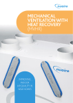
MRXBOX95-LH2 MECHANICAL SUPPLY & EXTRACT WITH HEAT RECOVERY
UP TO 95% EFFICIENT, SAP APPENDIX Q RECOGNISED.
LOFT MOUNTING DESIGN FOR LARGER HOUSES.
52
029 2085 8200
Nuaire Residential MVHR 1_Layout 1 12/08/2011 10:47 Page 53
MV H R
MR XB OX95- L H 2
TEC H NI C A L I NF O R MATI O N
B E NE F I T S
MRXBOX95-LH2 is designed to provide optimised balanced (supply and extract) mechanical ventilation with heat recovery. Tempered air is delivered into ‘living’ areas
whilst extracting moisture laden air from ‘wet’ areas, creating comfortable well ventilated homes. The unit has the facility to commission the supply and extract fans
independently on minimum speed (continuous background ventilation), boost control will control both fans to the same volume. The heat exchanger block can recover
up to 95% of the normally wasted heat.
MEETS BUILDING REGULATIONS
LIGHTWEIGHT
SAP Appendix Q recognised. Part F&L - England &
Wales. Scottish technical handbook (BRE398
referenced). Technical booklet K1998.
A one man lift for ease of install.
OPTIONAL REMOTE
FAIL INDICATOR
Quiet running unit, ensuring occupant acceptability.
MRXBOX95LH-RFI is
connected to the fan unit
via low voltage wiring.
To meet customer requirements on SAP scores
ensuring the reduction in emissions needed for
code level 3 and above (25% reduction).
CREATES A HEALTHIER ENVIRONMENT
DISCREET RUN MONITOR
High efficiency filters removes up to 95% of dust
particles.
Records units operational time.
LOW MAINTENANCE
PREVENTS CONDENSATION FROM LOFT
EXTREMELY LOW NOISE LEVELS
VERY HIGH EFFICIENCY
High quality components such as filters and EC
motors ensure lowest possible maintenance and
long life motors. Filter replacement typically every 5
years.
EASY TO USE
Well located controls for simple installation,
commissioning and use.
LOW POWER CONSUMPTION
OPTIONAL SUMMER BYPASS AVAILABLE
Reducing operating and the life cycle costs.
Provides cooling during warmer months.
MRXBOX95B-LH2.
COMPACT
Dedicated design ensured the most compact size for
duty on the market. The loft versions are specifically
designed to go through the smallest loft hatches.
5 YEAR WARRANTY
5 year parts and 1 year labour warranty guarantee
reduced life costs and peace of mind.
FLEXIBLE LOFT MOUNTING OPTIONS
REMOVABLE G4 FILTERS
Metal bracket
attached to unit
Washer Woodscrew
A. V. mount
Ceiling joist
Option 1. Mounted on roof joists
using four “L” shape metal brackets
and AV mounts on long sides of unit.
Side view example of an ‘L’
shaped fixing bracket and AV
mount attached to ceiling joist.
Option 2. Mounted on roof joists
using four “L” shape metal brackets
and AV mounts on short sides of unit.
Download specification from www.nuaire.co.uk/specifications
nuaire.co.uk
53
Nuaire Residential MVHR 1_Layout 1 12/08/2011 10:47 Page 54
MV H R
MR XB OX95B - L H 2
TEC H NI C A L I NF O R MATI O N
UNIT COMPONENTS
Filters, PCB and
Heat Exchanger Access
G4 removable filter.
Heat exchanger.
4 optional 150mm dia. knockout spigot
locations on rear of unit.
If required for use cut through the
acoustic foam round the circumference
of the knockout. (see figure above).
G4 removable filter.
Adjustment potentiometers and
indication lights.
Motor access.
4 x 125mm dia. spigots.
Panel not removable. Illustration purposes only.
DIMENSIONS (MM)
View from front 4 X 125mm spigots
Side view (controls)
4 alternative
150mm dia.
knockout spigots
on back of unit
430
Weight 21 Kg
Condensate
Drain
450
840
View from top
Side view (non controls)
21.5mm dia.
condensate
drain alternative
position
54
029 2085 8200
21.5mm dia.
condensate
drain alternative
position
Nuaire Residential MVHR 1_Layout 1 12/08/2011 10:47 Page 55
MV H R
MR XB OX95- L H 2
TEC H NI C A L I NF O R MATI O N
ELECTRICAL CONNECTION
Please note: the electrical connection of the unit must be be carried out
by a qualified electrician.
Ventilation controls
Electrical details:Voltage:
240V 1ph 50Hz
Consumption:
LH2 - 2.2 Amp
Fuse rating:
3 Amp
Boost
+ _
For commissioning
refer to user manual
Continuous
background
+ _ + _
Extract Supply Fan
Fan
Fan Failure
NOTE: This unit must be earthed.
L
L
N
FAN 2 SUPPLY
SUPPLY
SWL
N
FAN 1 SUPPLY
L
N
RED
YEL
WHI
BLU
RED
YEL
WHI
BLU
FAN 1 CTRL
FAIL
Connection to
Remote Fail
Indicator
FAN 2 CTRL
Fan
Connections
Connection to supply cord
230V IN
50Hz Mains
Detail of unit control on side panel.
The three core cable from the mains power supply should be connected
to a fixed wiring installation, via a fused isolator, in accordance with
current IEE wiring regulations.
Speed Control
Pots
Fan Failure
Indicator
Earth point
Note: Wiring is for reference
purposes only as the connections
above are factory fitted.
The unit is pre-wired with a
2 metre fly lead.
UNIT SERVING KITCHEN AND BATHROOM
MAINS
230V N
50Hz L
Room
Fuse 2A
light
Light
switch
(Double
Pole) Kitchen switch
Green/yellow
Blue
Brown
Black
3 Pole
isolator
Summer
bypass
switch
Supply cord
from unit
Grey (only used
on bypass unit)
UNIT SERVING KITCHEN AND TWO BATHROOMS
MAINS
230V N
50Hz L
Fuse 2A
Light
switches
(Double
Pole)
Room
lights
Kitchen switch
Download specification from www.nuaire.co.uk/specifications
Green/yellow
Blue
Brown
Black
3 Pole
isolator
Summer
bypass
switch
Supply cord
from unit
Grey (only used
on bypass unit)
nuaire.co.uk
55
Nuaire Residential MVHR 1_Layout 1 12/08/2011 10:47 Page 56
MV H R
MR XB OX95- L H 2
TEC H NI C A L I NF O R MATI O N
GENERAL ARRANGEMENT
OPTIONAL SUMMER BYPASS - MRXBOX95B-LH2
Filters, PCB and
Heat Exchanger Access
G4 removable filter.
Heat exchanger.
Three optional 150mm dia. knockout spigot
locations on rear of unit and one on the
side (non controls).
If required for use cut through the acoustic
foam round the circumference of the
knockout.
(see figure above)
G4 removable filter.
Adjustment potentiometers and
indication lights.
Motor access.
4 x 125mm dia. spigots.
Panel not removable. Illustration purposes only.
DIMENSIONS (MM)
Side view (controls)
View from front 3 X 125mm spigots
3 alternative
150mm dia.
knockout spigots
on back of unit
430
Weight 21 Kg
Condensate
Drain
450
840
View from top
Side view (non controls)
Alternative
150mm dia.
knockout
spigot
21.5mm dia.
condensate
drain alternative
position
56
029 2085 8200
21.5mm dia.
condensate
drain alternative
position
125mm dia.
spigot
Nuaire Residential MVHR 1_Layout 1 12/08/2011 10:47 Page 57
MV H R
MR XB OX95- L H 2
TEC H NI C A L I NF O R MATI O N
PERFORMANCE - MRXBOX95-LH2
Casing
MRXBOX95-LH2
700
ISO 5801 2007
AMCA 300
650
600
V
550
Type D
Air Density 1.2 kg/m3
500
Fan Static Pressure (Pa)
450
400
6
Code descriptions
350
300
5
MR-XBOX95-LH2
|
|
| | |
250
200
4
1
150
2
3 4 5
3
100
2
50
1
0
0
20
40
60
80
100
120
140
Air volume flow rate (l/s)
1. Multi-room supply and extract heat
recovery
2. Product range
3. Efficiency
4. Loft application
5. H2 = High 2 Model
SAP APPENDIX Q TEST RESULTS
Application
Specific fan
power (W/l/s)
Heat exchange
effIciency %
Energy Saving Trust Best
Practice Performance Compliant
Kitchen Plus 1 wet room
0.81
91
Yes
Kitchen Plus 2 wet rooms
0.77
91
Yes
Kitchen Plus 3 wet rooms
0.78
91
Yes
Kitchen Plus 4 wet room
0.86
91
Yes
Kitchen Plus 5 wet rooms
0.96
91
Yes
Kitchen Plus 6 wet rooms
1.09
90
No
MRXBOX95-LH2
E L E C T R IC A L & S OU N D
Curve
Maximum
power consumption
(Watts)
1
16
2
Sound Power Levels dB re 1pW
63
125
250
500
1K
2K
4K
8K
dBA
@3m
Open inlet
Open outlet
Breakout
36
40
40
33
38
38
34
39
36
24
38
30
22
32
21
19
30
21
20
29
20
23
30
18
13
22
14
30
Open inlet
Open outlet
Breakout
40
41
41
39
49
49
41
49
46
30
49
41
28
42
31
24
41
32
21
30
21
24
33
20
18
32
24
3
62
Open inlet
Open outlet
Breakout
43
50
50
42
53
52
54
59
56
38
60
52
37
52
41
31
52
43
30
42
33
33
34
30
29
42
34
4
106
Open inlet
Open outlet
Breakout
44
50
50
46
58
57
57
65
62
43
63
55
42
58
47
37
59
50
30
50
41
33
40
36
33
47
40
5
170
Open inlet
Open outlet
Breakout
46
51
51
48
61
60
58
70
67
52
74
66
48
64
53
42
64
55
30
56
47
33
48
44
36
55
47
6
277
Open inlet
Open outlet
Breakout
50
56
56
54
65
64
62
72
69
62
77
69
55
69
60
47
69
60
39
61
52
38
54
50
43
58
51
Hemisphical Free field dBA
The maximum power consumption shown above (Watts) is consumed on units running continuously,
not taking into account any heat recovery saving and based on SAP Appendix Q testing.
Download specification from www.nuaire.co.uk/specifications
nuaire.co.uk
57
Nuaire Residential MVHR 1_Layout 1 12/08/2011 10:47 Page 58
MV H R
MR XB OX95- L H 2
TEC H NI C A L I NF O R MATI O N
CO NSULTA NT S SP E CI F I C ATION
OPERATION
OPTIONAL SUMMER BYPASS - MRXBOX95B-LH2
The supply and extract ventilation unit shall be positioned as indicated on the
drawings and shall be in accordance with the particular fan schedule in the
specification.
The bypass damper opens when a 230V signal is applied to the unit (via a
manual switch, supplied). This opens the damper via an actuator. When the
switch signal is de-activated the unit returns to its original state (air through the
heat exchanger). Outside air supplied through the bypass is still filtered, so the
air quality is optimal, irrespective of the bypass setting (Open or closed).
The combined supply and extract with heat recovery unit, shall supply filtered
fresh air to each of the habitable rooms and vitiated air shall be extracted from
the wet areas e.g. bathroom, en-suite, w.c, kitchen, utility rooms, etc. The supply
air shall be pre-heated by the warm extract air via the integrated counter-flow
heat exchanger element. The extracted air shall also be filtered before it reaches
the heat exchanger block.
The ventilation unit shall vary its speed and therefore the ventilation rate, as it
receives signals from one of the following:
• Switched live signal from light / remote switches.
When signals are received, the fan shall alter its speed to adjustable, normal and
boost rates.
The unit shall have the facility to commission the supply and extract fans
independently on minimum speed (continuous background ventilation), boost
control will control both fans to the same volume, via inbuilt minimum and
maximum speed adjustment;. The fans shall have infinitely variable speed control.
MRXBOX95-LH2 - UNIT SPECIFICATION
The unit shall be fully insulated providing excellent thermal and acoustic
characteristics and shall be complete with a multi plate counter flow high
efficiency heat exchanger block, with a thermal efficiency of up to 95%. The heat
exchanger shall be protected by G4 grade filters on fresh air inlet and system
extract. The heat exchanger and filters shall be accessible via the top access
panel, enabling quick and easy maintenance.
The unit shall have low energy, high efficiency EC fan/motor assemblies with
sealed for life bearings, the impellers shall be backward curved centrifugal type.
The motors shall be suitable of an ambient temperature of 40ºC.
The unit shall be supplied complete with an insulated condensate drip tray and
21.5mm drain connection.
The unit shall be suitable for 150mm or 125mm circular ducting. Anti-vibration
mounts are supplied with each unit to prevent vibration being transmitted to
the ceiling timbers.
The breakout noise level and power requirements shall be as detailed by the unit
manufacturer and in accordance with the ventilation equipment schedule.
58
029 2085 8200
MRXBOX95-LH2 - CONTROL OPTIONS
All versions shall have the following functions integrally mounted within the fan
unit on a purpose made PCB, all such components pre-wired and factory fitted
by the manufacturer: • Independent control of background supply and extract flow rates.
• Single control of boost ventilation rates
• Run time monitor included
• Integral Fan failure indication.
• Integral S/L terminal for boost from remote switch, e.g. light switch.
OPTIONAL CONTROL
MRXBOX95LH-RFI Remote fail indicator.
Units shall be the MRXBOX95-LH2 as manufactured by Nuaire.