1
4 INSTALLATION
4.1
MOUNTING DETAILS
Currently SmartScan is for bench top use; other mounting arrangements including DIN rail
available on request.
4.2
OPTICAL CONNECTIONS
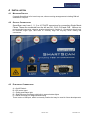
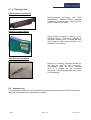
SmartScan may have 1, 2, 3 or 4 FC/ACP connectors for connecting Single Mode
Fibres. These are numbered from the left as CH1, CH2, CH3 and CH4. Observe the
recommended connector cleaning practice described in Section 6. Connectors should only
be fastened finger tight, take care to correctly align the key-way when mating the
connectors.
4.3
ELECTRICAL CONNECTIONS
A = On/Off Switch
B = DC power Input
C = Power and Status light
D = RJ45 Ethernet Connector with built-in network status lights
E = Serial connector for diagnostics/servicing
There is also a USB port, which is currently inactive but may be used in future developments
Page 6
30th Aril 2013
3100-3002 Iss E