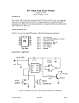
1
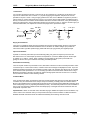
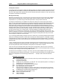
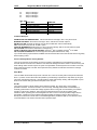
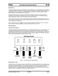
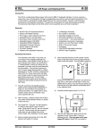
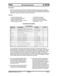
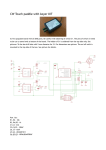
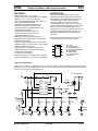
K1EL
K12
Single Chip Morse Code Keyer/Processor
FEATURES
DESCRIPTION
• Keyer speed range: 5 - 59 WPM
• HSCW: 1000, 1500, 2000, 3000, 4000 or 6000 lpm
• QRSS: 3, 6, 10, 12, 30, 60 second dits
• Non-Volatile Message Memory: 240 letters in six
slots with embedded commands.
• Dynamically allocated message memory
• Backspace supported on message entry
• Keying Modes: Bug, Ultimatic, Iambic A or B
• Serial Number Generation
• Audio Frequency keying mode (PTT)
• Adjustable Letter Spacing 25 to 75%
• Adjustable Weight 25 to 75 %
• Automatic letterspace mode (Autospace)
• Adjustable Keying Compensation 0 to 31 mSec
• Paddle swap command
• Beacon: Programmable interval: 1 to 99 seconds
• Sidetone Output: TTL Square wave, 100Ω output Z
• Adjustable Sidetone frequency
• Keying output: TTL, high true when keyed
• Optional Speed control potentiometer support
• Push-button user interface
• 22 easy to use commands
• Operating Voltage: 2.5-5.5 VDC, built in oscillator
• Power Consumption: <1 ma active, 1 µA standby
The K12 is a single chip Morse keyer with an
extended set of features that will be described in
this datasheet. It is implemented in a Microchip
PIC12F683 single chip microprocessor and
requires minimal components to construct a
powerful Morse keyer. The K12 has a rich set of
commands that are entered directly in Morse code.
When not in use it automatically goes into low
power and can be run off a single battery for many
months. All settings inside the K12 are stored in
EEPROM so that if power is removed they are
preserved.
Pin compatible with K10 and K10+ keyer ICs, but
requires a pull-up resistor from pin 1 to pin 4.
1
8
2
7
3
K12
4
Pin
Pin
Pin
Pin
Pin
Pin
Pin
Pin
6
5
1: VCC
2: Key/PTT Out
3: Sidetone/AF Out
4: Command Pushbutton
5: Dit Paddle
6: Dah Paddle
7: Switch Network
8: Ground
Top View
Typical Keyer Application
Figure 1 is a schematic of a complete K12 keyer. The switch resistor network, the MSG2-6 switches, and the rate
pot driving pin 7 provide optional features. Tie pin 7 to pin 1 if it is not used. The command push-button provides
access to command mode and message one.
To Transmitter
.1 µF
K12
1
2
3
100Ω
4
Vcc
K
4.7K
Gnd
8
7
Net
6
6
Tone Dah
5
Cmd
Dit
Key
L
.01 µF
4.7K
15K
3V
2N7000
Paddle
R
AF
S
.01 µF
47K
33K
27K
SPKR
39K
22K
5K
Load
Speed
CMD/
MSG1
K12 Keyer Datasheet
MSG2
MSG3
MSG4
10/29/2010
MSG5
MSG6
Page 1
K1EL
Single Chip Morse Code Keyer/Processor
K12
Construction
You can either purchase the K12 kit or a K12 keyer can be constructed on a small piece of perf-board. The
layout is not critical but be sure to include a .1 µF power supply bypass capacitor and place it as close as
possible to K12 pins 1 and 8. If using a supply greater than 3 volts, use an LM2936-3.3 regulator to provide 3
volts for the K12. Use the interface shown in Figure 3 if you wish to drive a small speaker. If installing the K12
directly in a transceiver, the sidetone audio should be fed into the receiver's audio chain, it may be necessary to
reduce the output level by using an attenuator network such as shown in Figure 4. Select R1 and R2 to give you
the desired attenuation, The capacitors round the sharp edges of the square wave output.
100Ω
Vcc
8Ω Spkr
R1
From K12
Pin 3
2N2222
From K12
Pin 3
Figure 3
.1µF
R2
To AF Input
.1µF
Figure 4
Keying Considerations
The K12 is not capable of directly keying a transmitter and requires a buffer between the keyer chip and the
transmitter. A 2N7000 FET transistor is utilized in the k12 kit which can handle voltages up to positive 60
volts. Most modern rigs utilize positive keying while older tube style rigs generally are negatively keyed.
Input Considerations
A paddle or command push-button input is activated by pulling it to ground. Pull-ups for pins 5 and 6 are
built into the K12 so no external pull-up resistors are required. Pin 4, however, does require an external pullup resistor (4.7 to 10KΩ). A shunt .001uF capacitor is recommended on all inputs to prevent RF from
getting into the K12 from your transmitter and causing unreliable operation.
Push-button Functionality
The K12 requires at least one push-button control, this switch is referred to as the command push-button and is
connected to pin 4. It serves two functions, command control and message record/playback control. Up to five
additional message push-buttons can be added to provide a total of six message slots. Be sure to use normally
open switches for the push-buttons. Pin 7 is an analog input which senses the switch network shown in Fig 1.
Message push-buttons 2 through 6 as well as an optional analog speed control all connect to Pin 7 as shown.
Use 5% tolerance resistors for the switching network.
Command Mode
If the command push-button is pressed and held, the K12 will respond after about two seconds with the letter R
in sidetone only. This means the K12 is ready to accept a command, you simply enter the command letter in
Morse on the paddles and the command will be executed. Some commands require additional information which
the K12 will prompt you for by outputting the letter E (for enter). All commands provide some sort of feedback to
tell you if the command was understood and executed properly. If an illegal command is entered the K12 will
respond with a question mark.
Important Note ! When in command mode, transmitter keying is disabled and replies are sent in sidetone only.
Thus in order to use command mode you must provide some way to hear the sidetone. If sidetone had been
disabled with the A command it will be re-enabled automatically when entering command mode.
K12 Keyer Datasheet
10/29/2010
Page 2
K1EL
Single Chip Morse Code Keyer/Processor
K12
K12 Command List
A
C
D
F
H
I
J
K
L
M
N
-
Select sidetone on or off
Set command speed in WPM
Decrement serial number
Select serial number 0/9 format
Set Fast/Slow AFK tail delay
Set Letter Spacing
Set Paddle sensitivity
Select keyer mode
Load message memory slot
Mute Transmit (CPO mode)
Load 4 digit serial number
O
Q
R
S
T
U
V
W
X
Y
Z
-
Set output keying format
Query current WPM speeds
Review message without transmitting
Set CW transmit speed in WPM
Key transmitter for tuning
Select Autospacing on/off
Set Keying compensation in mSec
Set Key Weight
Exchange Paddles
Analog input diagnostic
Select sidetone frequency
In the command descriptions below, the [n] or [nn] notation means that additional parameters must be entered
on the paddles after the command. A letter displayed in BOLD is something you enter, BOLD ITALIC is what
the K12 responds with. A [pb] means that the K12 will wait for you to press one of the message pushbuttons.
A - Sidetone enable is toggled when this command is entered. Toggle means if the sidetone was on when this
command was issued it will be turned off and vice versa. The K12 will acknowledge this command by responding
with an R. Note: If sidetone is disabled it will be re-enabled while in command mode.
C[nn]- This command is used to set the command Morse speed of the K12. The K12 can use different speeds
for command and transmit Morse speeds. Changes in transmit speed will not affect command speed. After the C
command is issued enter the speed in WPM. See the S command for details on entering Morse speeds.
D – Decrement serial number by 1, K12 responds with an R
F – Toggle serial number format for 0 and 9. K12 responds N for normal, A for 0 sent as T and 9 sent as N
H - Sets the transmit PTT hang delay time in AFK mode. You can select one of two delays; a fast delay which is
1.5 word space times and a slow delay which is 3 word space times. This is a toggle command. An S or L is the
K12’s response to this command (S=Short, L=Long).
I[nn] – The space between characters can be adjusted as a percentage. The range is 25% to 75%, 50% is
normal spacing with no adjustment. Less that 50 tightens spacing, greater than 50 loosens spacing.
J[nn] - This controls when the K12 will start looking for a new paddle press after sensing the current one. If
there is not enough delay the keyer will send unwanted dits or dahs, if there is too much delay it bogs you
down because you can't get ahead of the keyer. The default value is one dit time (50) and is adjustable in
percent of a dit time. Faster operators report a setting somewhat less than default is more pleasing. If the
paddle sensitivity is set to zero, both dit and dah paddle memories are disabled. The delay is
calculated with this formula:
DELAY_TIME = (nn×DIT_TIME)/50 where Switchpoint is a value between 01 and 99.
K – There are six different keying modes supported by the K12: Iambic mode A and B, Straight Key, Bug,
Ultimatic, Dit priority mode, and Dah priority mode. In either iambic mode, alternating dits and dahs are sent
while both paddles are held closed. In mode B an extra alternate dit or dah is sent after both paddles are
released. In straight key mode a dah paddle press will key the transmitter for as long as the paddle is
pressed. Use the swap command: X to choose either the left or right paddle Bug mode directly keys with the
dah paddle and generates dits automatically when the dit paddle is pressed. In Ultimatic mode when both
paddles are pressed the keyer will send a continuous stream of whichever paddle was last pressed. Dit and
dah priority mode will generate dits and dahs automatically in response to single paddle presses, but when
both paddles are pressed either dit or dah has priority.
When the K command is issued the current mode is sent, and by pressing the dah paddle the user can cycle
through the six modes: A (iambic A), B (iambic B), S (straight), V (bug), U (ultimatic), E (dit pri), T (dah pri).
Press the cmd PB to apply the selection. The K12 will leave straight and bug key mode and go to iambic A mode
for command entry but will return after the command is complete.
K12 Keyer Datasheet
10/29/2010
Page 3
K1EL
Single Chip Morse Code Keyer/Processor
K12
L [pb] – The L command is used to load the message memory slots. There is a detailed description of message
loading in the Message Functionality section.
M – Toggle transmit muting, useful for off line practice. K12 responds with R
N [nnnn] – The N command is used to load a 4 digit serial number. All four digits must be entered including
leading zeroes. The serial number is played by inserting a play message token /N into a message. The serial
number is automatically incremented after playing. See Embedded Command section for more details.
O – The K12 provides three different keying output modes. Normally sidetone is output on pin 3 and keying is
output on pin 2. In AFK keying mode Pin 2 acts as a PTT line and stays low for the entire keying interval while
sidetone is sent on pin 3. In External oscillator mode, pin 2 acts as PTT while pin 3 is asserted to key and
external tone oscillator. External oscillator mode is useful for HSCW operation.
Pin 2 Normal
Pin 3 Operation
Pin 2 AFK
Mode
Pin 3
Pin 2 External
Pin 3 Oscillator
Each time the O command is issued the keying mode will advance to a different mode. N signifies normal, A
signifies AFK, and X signifies external modes,
Q - This command is used to query the K12 about its current settings. After the command is issued the K12 will
respond with K12 commands and their settings are sent in the following format:
nn Fnn Snn Cnn Wnn Vnn Jnn Inn. The F value is the free message memory available.
You can stop the response any time after the first parameter is sent by pressing the command pushbutton.
R [pb] - You can review a message without transmitting with this command. After the R command is entered the
K12 will respond with an M. You then press the message button of the message you wish to play. The message
will be sent in sidetone only. If you try to play an empty slot the K12 will respond with MT. Embedded commands
will be sent as is without expansion.
S [nn]- The Morse sending speed is set with this command. The new value is entered directly in WPM in the
following manner. After the S command is issued the K12 will respond with a single E, you then directly enter the
speed. As a short cut, a T can be entered for zero. If the desired speed is a single digit, either enter the single
number, or send a zero or T first. i.e. 7 or 07 or T7 will all give you 7 WPM. Likewise, 2T can be entered for 20
WPM. If an illegal value is entered, the K12 will respond with a question mark, if the value is good the K12 will
respond with an R.
T - After a brief pause, this command will key the transmitter for tuning. The K12 will stay in tune mode until the
command push-button is pressed.
U - This command toggles autospace mode. When autospace is enabled the K12 will automatically insert proper
inter-letter space between letters. Each time the U command is issued the K12 will toggle between modes
responding with an A for autospace enabled an N for autospace disabled.
Here is how autospace works: If you pause for more than one dit time between a dit or dah the K12 will interpret
this as a letter-space and will not send the next dit or dah until the letter-space time has been met. The normal
letter-space is 3 dit spaces but this can be increased by using the F command. The K12 has a paddle event
memory so that you can enter dits or dahs during the inter-letter space and the K12 will send them as they were
entered. With a little practice, autospace will help you to send near perfect Morse.
V[nn] – Keying Compensation allows a fixed amount of time to be added to the length of all dits and dahs.
QSK keying on modern transceivers can cause shortening of these elements which is especially noticeable
at high speeds. The K12 allows the length of the elements to be increased uniformly to compensate for this.
The adjustments can be made in one-millisecond steps. The maximum adjustment is 31 mSecs. Key
compensation is very similar to Weighting in that any adjustment added to the dits and dahs is subtracted
K12 Keyer Datasheet
10/29/2010
Page 4
K1EL
Single Chip Morse Code Keyer/Processor
K12
from the spacing so the resulting speed is not changed. The difference between weighting and keying
compensation is that compensation is independent of speed, so if 10 mSec of key compensation is selected,
10 mSec will be always be added regardless of speed. So be careful at high speeds with large values of
keying compensation, dits and dahs may run together with no spacing at all.
Letter R without compensation
nn
Letter R with compensation
W[nn] – The keying weight can be adjusted in percentage from 25% to 75%. When set to 50 % the dit time
is equal to the inter-element time, which is normal. Values less than 50 reduce weighting while values
greater than 50 increase weighting. Note that weighting does not affect sending speed because any
increase in keyed time is subtracted from spacing time. Reduction in weighting results in a thinner sound
while increased weighting results in a heavier sound. Since weighting tracks speed, a given weighting will
sound the same at all speeds.
25 % weighting
50 % weighting
75 % weighting
X - This command will cause the K12 to exchange paddle Inputs (dit and dah). The K12 will always respond with
a letter R to signify that this command was accepted.
Y - Analog input diagnostic. This command is used to verify the correct operation of the switch network
connected to the analog input pin 7. The voltage divider network allows three switches and a potentiometer to
share a single pin on the K12. The K12 contains an analog to digital converter, which can accurately measure
the voltage on Pin 7 and determine which switch is activated.
After the Y command is issued, the analog input value on pin 7 will be sent in Morse in sidetone. Simply press a
push-button or enable the speed potentiometer to obtain a reading. For proper operation the input values must
fall within the following ranges:
No switch ............ 255 to 204
PB 5 ................... 169 to 157
PB 2 ................... 204 to 189
PB 6 ................... 156 to 139
PB 3 ................... 188 to 180
Speed Pot .......... 60 to 0
PB 4 ................... 179 to 170
Z - This command allows the sidetone frequency to be modified. After this command is entered the sidetone
oscillator will be turned on. Pressing the paddles will raise or lower the frequency. There are 13 possible
choices: 2000, 1333, 1000, 800, 666, 570, 500, 440, 400, 363, 333, 307, and 285 Hz. Pressing the command
push-button will end this command and store the new sidetone frequency. Due to the multi-threaded processing
architecture of the K12, continuous sidetone frequency selection is not possible.
Speed Potentiometer Functionality
The K12 supports the use of a potentiometer to set sending speed. The “speed pot”
is read using the K12’s analog input pin 7 which is shared with the message pushbuttons. Only one device, either a push-button or the speed pot, can be enabled at
a time. This is why the pot must be switched in and out of the circuit. Another
important reason is to reduce the power consumption in power down mode. Note
that the pot is optional, speed can also be set by either the S command or by the
Fast Speed Set feature described in the next section. To use the speed pot simply
press the pot enable button and the K12 will output dits at the current speed in
sidetone, just turn the knob to get the desired speed. The speed pot range is a
subset of the entire speed range of the K12, 10 to 40 WPM. The speed pot’s range
can be tailored by adjusting the value of the pot and/or adding series resistance.
Note that the absolute maximum speed pot setting is 50 WPM. A log taper pot is
recommended for improved linearity.
Vcc
15KΩ
To K10
Pin 7
5KΩ
Speed
Set PB
Figure 5
K12 Keyer Datasheet
10/29/2010
Page 5
K1EL
Single Chip Morse Code Keyer/Processor
K12
Fast Speed Set Feature
The sending speed can be quickly changed in 2 WPM increments by holding the command push-button and then
pressing either the dit or paddle. You must press the paddle before the normal command mode time-out occurs,
but once in fast change mode it will stay there until the command push-button is released. A dit is sent each time
the speed is incremented or decremented.
Message Functionality
Messages are loaded using the L command. After the command is issued the K12 will respond with an M after
which the desired message button must be pressed. When the K12 is ready to accept a new message, it will
respond with an I. If you wait too long the K12 will respond with a ? and you have to start over.
A message is entered directly on the paddles at a steady rate, making sure to leave proper space between
letters. To insert a word space simply pause for longer than a letter space and the K12 will respond with an E to
signify a word space insertion. When the message has been completely entered press the command pushbutton and the K12 will respond with an R to signify that the message was accepted and stored. If an error is
made while entering a message, press and hold the command push-button and the K12 will backspace through
the letters entered. When you reach the position you want, release the button and enter more letters. If the
message memory becomes full while entering a message, the K12 will stop further loading, respond with a F,
and return the K12 back to non-command mode. There are 236 letters in message memory that can be
distributed in any way between six message slots. The length of the individual message slots is not fixed. This
means, for example, you could have one message of 80 characters, one message with 5 characters, and a third
with 10 characters and still have 141 locations left to split among the remaining three slots. Keep in mind that
each word space occupies one memory location.
If you are having problems loading messages into the K12, make sure you are leaving adequate space between
letters and not sending much faster or slower than the currently set command speed. If, for example, you enter
an A followed by a T and end up with an W, you are not allowing enough space between letters. It’s a fine line
though because if you allow too much space the K12 will interpret that as a word space. Lowering the command
speed can help.
To play a message back simply press the desired message button and the message will be sent. If you want to
review the message without keying the transmitter, use the R command. To abort a message being sent, press
the command push-button and the transmission will stop after the current letter is complete.
There is a short cut for message loading. After pressing the command button, wait for the K12 to send an R,
release the command button and then press the desired message button. The K12 will respond with an I and you
can directly enter a message without entering the M command.
Commands can be embedded in a message. The format is the slash character DN (D and N sent together as
one letter) followed by the desired command letter. If you want to insert the DN prosign into a message but don’t
want it to be interpreted as a command simply enter DN twice.
Example: K1EL/1 would be entered as
K1EL//1
Embedded command table
/Bnn
/D
/Gn
/Hn
/Knn
/N
/P
/Q
/Snn
/Wnn
/1
/2
Set a beacon cycle time of nn seconds (nn=00 to 99). Put this at the beginning of a message
to set the beacon period.
Decrement serial number
Set Gap (n=0 to 5) Letterspace = (2+GAP) dits. This can be placed anywhere in a message. A
gap will stay in force until set back to zero.
Set HSCW speed. See table below for determining n.
Key transmitter for nn seconds (nn=00 to 99)
Play Serial Number with auto increment.
Pause and wait for paddle entry and then continue after one word space time. The pause is
ended three ways 1) paddle entry 2) Press a msg PB (2-6) or 3) Press the cmd PB to cancel.
Set QRSS speed. See table below for determining n.
Set a new sending speed (nn=WPM, 5 to 59)
Wait for nn seconds (nn=00 to 99)
Jump to message 1
Jump to message 2
K12 Keyer Datasheet
10/29/2010
Page 6
K1EL
Single Chip Morse Code Keyer/Processor
/3
/4
/5
/6
K12
Jump to message 3
Jump to message 4
Jump to message 5
Jump to message 6
Rate Table
n
HSCW Rate
0
1000 lpm (200 wpm)
1
1500 lpm (300 wpm)
2
2000 lpm (400 wpm)
3
3000 lpm (600 wpm)
4
4000 lpm (800 wpm)
5
6000 lpm (1200 wpm)
QRSS Rate
3 sec dit
6 sec dit
10 sec dit
12 sec dit
30 sec dit
60 sec dit
Command Examples
/B60BCON DE K1EL BEDFORD NH/1 will send this beacon message in slot 1 every 60 seconds
BCON DE K1EL/W60/4 will send this message in slot 4, wait 60 secs and then repeat it
UR RST IS /P QSL will pause to allow the user to enter the RST then resume automatically
/1EL /1 will continuously send EL at QRS 3 speed
/K05 K1EL BCON/W10/R will key down for 5 secs, send the message, wait 10 seconds and then repeat
CQ CQ CQ DE /1 will send the call loaded in message slot 1
st
nd
/H2CQ CQ DE K1EL K1EL K1EL/S15DE K1EL will send 1 part at 1500lpm and the 2 at 15 WPM
CQ CQ CQ DE K1/G2ISI/G0 will send message with extra space between ISI for clarity
Try to avoid inserting a space between a QRSS command and the start of text since this will cause a long delay
before anything is sent.
Preserve Settings/Restore Factory Defaults
The K12 can save the current settings. It’s done by pressing and holding the command button for about 4
seconds until the K12 sends a P in sidetone. This means the settings have been stored in internal memory and
those settings will be restored if power is cycled. If the pushbutton is held beyond the P for another 4 seconds,
the K12 will send a series of six dits. At that point the factory defaults are restored. Note that the message
contents are erased.
Sleep Mode
The K12 utilizes the automatic sleep mode of the PIC CPU. The K12 normally rests in sleep mode and draws
about 1 µA of DC current. When either the paddles or push-button(s) is pressed, the chip wakes up and goes
into active mode drawing less than 1 ma idle and about 10ma while actively sending. After the paddle or pushbutton is serviced the K12 goes back to sleep after a few seconds.
K12 Kit
The K12 kit consists of a single sided pc board, sidetone speaker, key output driver, and a multiple
pushbutton interface. The kit can be built in one of two ways, internally powered with on board battery or
externally powered with on board LDO voltage regulator. When running with on board battery, the sidetone
frequency must be set to 2000 Hz. This is gives the loudest audio level out of the low voltage audio
transducer. When operating with on board regulator the K12 is run at 5 volts and provides a higher drive to
the speaker. A simple circuit is provided to attenuate and filter the sidetone output to allow it to be fed
directly into a transceiver’s audio chain in embedded applications (PCB board pad A). This allows the K12’s
command sidetone to be heard in the transceiver’s speaker output.
K12 Keyer Datasheet
10/29/2010
Page 7
K1EL
Single Chip Morse Code Keyer/Processor
K12
K12 Kit Assembly
Parts Inventory
U1
U2
Q1
R1
R3
R2, 4
R5
R6
R7
R8
-
K12 8 pin DIP IC
LM2936Z 3.3V regulator TO92 *
2N7000 Transistor TO92
100Ω ¼ (brown black brown)
15KΩ ¼ watt (brown green orange)
4.7 KΩ ¼ watt (yellow violet red)
47KΩ ¼ watt (yellow violet orange)
39KΩ ¼ watt (orange white orange)
22KΩ ¼ w (red red orange)
33KΩ ¼ w (orange orange orange)
R9
C1, 2, 5 C3, 4 C7
C6
B1
S1
-
27KΩ ¼ w (red violet orange)
.01 µF ceramic capacitor 103
.001 uF ceramic capacitor 102
.01 µF ceramic disk capacitor 103 *
100 µF electrolytic cap (blue) *
Battery holder **
Mini speaker
8 Pin DIP Socket
PC board
* Non battery powered, ** Battery powered
PCB Assembly
Test Procedure
Install the resistors first, be careful to install
the correct values in R3, R5, R6, R7, R8 and
R9. Install the 8 pin DIP socket, locate the
index mark in the socket to match the PCB
silkscreen. Install a scrap resistor lead in J1.
Install U1, carefully aligning pin one as shown in
this diagram:
1
8
Install Capacitors C1, C2, C3, C4, C5.
Now install Q1. Carefully form the leads so
they will line up with the PCB holes in such a
way that the flat side of the TO92 package
lines up with the silk screen, solder in place.
K12-BAT: B1 battery clip.
K12-EXT: Install U2, C6, C7. Note: an
alternate regulator may be supplied for U2.
Install and solder the mini speaker. Align
polarity markers on the speaker and PCB.
Install the battery and you should hear one “R”
(di-dah-dit) in Morse from the speaker. Use a
piece of jumper wire to ground the L and/or R
points on the PCB and you should hear dits and
dahs. Ground the M1 point and you’ll hear an
R. If you ground M2, M3, M4, M5, or M6 the
keyer will send MT.
If you don’t get any of these tests to work
carefully check the board for miswires or solder
shorts. Refer to the images of the solder side
and silkscreen to aid in your debugging.
Now you can finish wiring up the paddle, keying,
and push button connections. The K12 can be
installed directly in your transceiver or in a
separate enclosure.
K12 PCB Silkscreen and Bottom Layer Images
K12 Keyer Datasheet
10/29/2010
Page 8
K1EL
Single Chip Morse Code Keyer/Processor
LM2936Z-3.3
7-15 VDC
In
V+
Gnd
C6
+
U2
.01µF
G
K12 Kit Schematic
K1EL - 10/26/2010
Out
C7
K12
+ B1
3V
Battery
CR2032
1µF
To Transmitter Key
Populate U2, C7, and C6 for external
or B1 for internal power
K
Q1
R4
4.7KΩ
C5
.01 µF
100V
2N7000
U1 K12
R3 - 15K
R2 - 4.7K
C2 .01 µF
1
2
3
4
Vcc
Gnd
8
Key
Paddle
L
7
Net
6
6
Tone Dah
5
Cmd
Dit
R
C3
.001 uF
C4
.001 uF
J1
R6
39K
R5
47K
R7
33K
R8
27K
S1
R9
22K
SPKR
R1
AF
CMD
M2
M3
M4
M5
M6
P
100
C1
.01µF
Audio
Output
5K
Load
Speed
CMD
MSG2
MSG3
MSG4
MSG5
MSG6
K12 Tutorial
We’ll start with power on: after a short initialization time the K12 will output the letter R to let you know it’s
ready. If you hold the dah paddle down while turning power on, the K12 will output the firmware version
letter (A-Z). On 1st time power up the K12 will be reset to factory defaults which are:
Operating WPM:15
Command WPM:15
Sidetone:2KHz
Weight:50%
KeyComp:0
Interchar Spacing:50%
SampleAdjust:50%
KeyMode:Iambic B
Sidetone:On
Autospace:Off
OutputMode:Normal
Serial Number:0001
Now press the paddle keys and the K12 will generate dits and dahs both in sidetone and keyed output. Let’s
K12 Keyer Datasheet
10/29/2010
Page 9
K1EL
Single Chip Morse Code Keyer/Processor
K12
enter a simple command to swap the paddles. Press the command pushbutton (CMD PB) until the K12
answers with an R. Then, without hesitation, enter an X on the paddles. The K12 will answer with an R
letting you know the command succeeded. If it did not understand the command or you are too late to enter
a command the K12 will respond with a question mark. To swap the paddles back enter the X command
again. Next let’s change the command entry speed. You’ll enter the C command followed by the desired
speed, let’s try 10 WPM. Press the CMD PB, wait for the R, and then enter C. The K12 will respond with an
E telling you it’s waiting for you to enter something. You then enter a 1 followed by a 0. Try it again but this
time use a T for the zero. This is a handy shortcut. The operating speed is set in the same manner using the
S command. Now try the ‘fast WPM’ feature: Press and hold the CMD PB while you tap the paddles. One
side increases the speed, the other decreases speed. There’s a two WPM change for each press, a dit is
echoed for each change. You can move very quickly by counting the dits up or down. Next we’ll change the
keying mode. Enter the K command and the K12 will tell you what mode it is currently in (see page 3). Press
the dah paddle to cycle through the six modes. Give each one a try to get familiar with how they work. Now
might be a good time to select the one you think you’ll be using. When you are done press the CMD PB to
get back to normal operation. The sample adjust command will allow you to tweak the paddle sensitivity to
home in on the way you want the paddles to respond. By setting sample adjust to zero you can disable the
dit and dah paddle memories. You can save your settings in internal EEPROM at any time by pressing the
CMD PB until the K12 responds with an R and then a P. The Weight, Keying compensation, and letterspace
commands adjust the way Morse is generated. If you are using a battery powered K12 kit the sidetone
should be left at 2 KHz, otherwise you can play around with sidetone frequency by using the Z command.
Press the paddles to adjust the sidetone frequency, hit CMD PB when done. Now let’s play with messages.
Review the procedure for message loading on page 6. The K12 has two great features associated with
messages. The first is backspace, if you make a mistake while entering a message just backspace to fix the
error. The second is non-fixed message slot sizes, if you only use two bytes in slot one, only two bytes of
message memory are used up, not an entire slot. Once you have mastered message loading you can tackle
some embedded commands. An easy one to start with is a speed change command. In slot one enter:
/S10SLOW /S25FAST. This message will play at two different speeds. Note that after playing this message
the operating speed will be left at 25 WPM. We can compose a beacon command easily: In msg slot 2
enter: /B60/K05 BCON DE K1EL NH/2 It will key down for 5 seconds, send BCON DE K1EL NH and repeat
this every 60 seconds. To cancel a beacon simply press the CMD PB, K12 will stop the loop and respond
with an X to let you know something was cancelled. Serial numbering is easy to use. First enter a starting
serial number with the PB CMD N. You need to enter all four digits including leading zeroes. Next select the
way you want the K12 to send 0s and 9s in a serial number. Use the CMD PB F command for this. To
compose a message that will play a serial number, enter: CQ DE K1EL/P UR NR/N QSL?/P in slot 3. This
message will send CQ and then pause to let you listen for a reply. If no reply, hit msg PB 3 to repeat the CQ.
If there was a reply enter the station’s callsign and the K12 will send the serial number and pause again. If
the station needs a repeat of the callsign press 2 to play this message in slot 2: UR NR /D/N QSL ? Since
the serial number is incremented after an /N command you need to pre-decrement it to send the original
number. The /P command is a three-way branch, 1st branch: paddle something to continue, 2nd branch: hit a
msg button (other than CMD PB), 3rd branch: hit the CMD PB to cancel the message. Since MSG1 = CMD
PB you can’t use slot one as a 2nd branch choice. The K12 supports two alternate sending rate modes. They
are selected by putting embedded commands in the message. QRSS is extremely slow CW for VLF work,
and HSCW is extremely fast CW typically used for QSOs via meteor scatter. Here are examples of each:
QRSS: /K10/ Q2EL/2 Keydown for 10 seconds followed by EL at QRSS6 rate, will repeat in slot 2
HSCW: /H3K1EL K1EL K1EL K1EL K1EL K1EL K1EL /1 The call is repeated in slot 1
There are three output modes. Normal mode is keying output on pin 2 and sidetone on pin 3. Mode two
allows you to run in audio frequency keyed mode. Pin 2 keys the transmitter while pin 3 provides a keyed
tone to feed into a microphone. Mode three is used mainly for HSCW, it allows you to use the K12 to key an
external crystal based tone oscillator.
The K12 keyer is fully guaranteed; if you are not satisfied please return the K12 for a full refund.
Questions will be handled by snail-mail or e-mail via these addresses:
Steven T. Elliott K1EL
43 Meadowcrest Drive
Bedford, NH 03110 USA
or e-mail: [email protected]
Watch the K1EL Website for latest updates and new product offerings: http://www.k1el.com
Revision History
Chip Rev A Original Release
Chip Rev D Fixes for leading zero in serial number and mixed QRSS and normal speeds in message.
K12 Keyer Datasheet
10/29/2010
Page 10