1
Preface
Thanks for choosing the E550 series universal low-power inverter produced by
Shenzhen Sunfar Electric Technologies Co., Ltd.
This Manual is the operating manual for E550 series universal low-power
inverters. It provides all relevant instructions and precautions for installation,
wiring, functional parameters, daily care and maintenance, fault diagnosis and
troubleshooting of E550 series inverters.
In order to use this series of inverters correctly, guarantee product's best performance and ensure safety of users and equipment, be sure to read this
manual carefully before using E550 series inverters. Improper use may cause abnormity and malfunction of the inverter, reduce its service life and even damage equipments and lead to personal injury and death, etc.
This user manual is delivered with the device. Please keep it properly for future
overhaul and maintenance.
Owing to constant improvement of products, all data may be changed without
further notice.
User Manual of E550 Series Universal Low-Power Inverter
Version V1.1
Revision Date: May 2013
Contents
1. ODUCT INTRODUCTION................................................................................ 1
1.1 DESCRIPTION OF INVERTER MODEL...............................................1
1.2 MODEL OF INVERTER SERIES.........................................................1
1.3 PRODUCT APPEARANCE AND NAME OF COMPONENTS...................1
1.4 PRODUCT TECHNICAL INDICATORS AND SPECIFICATIONS.............. 2
2. INVERTER INSTALLATION............................................................................5
2.1 ENVIRONMENTAL REQUIREMENTS.................................................5
2.2 INSTALLATION DIMENSION OF INVERTERS.....................................6
3. INVERTER WIRING..........................................................................................9
3.1 WIRING PRECAUTIONS...................................................................9
3.2 WIRING OF PERIPHERAL ELEMENTS.............................................10
3.3 BASIC WIRING..............................................................................12
3.4 WIRING OF MAIN LOOP TERMINAL.............................................. 13
3.5 WIRING OF CONTROL LOOP TERMINAL........................................14
4 . ERATING PANEL............................................................................................ 15
4.1 FUNCTION DESCRIPTION OF KEYS................................................15
4.2 PANEL OPERATING METHOD.........................................................16
4.3 LIST OF STATUS MONITORING PARAMETERS................................ 17
4.4 SIMPLE OPERATION OF THE INVERTER.........................................18
5. UNCTION PARAMETER TABLE.................................................................. 20
6. UNCTION DETAILS.........................................................................................30
6.1 BASIC RUNNING PARAMETER GROUP...........................................30
6.2 ANALOG INPUT OUTPUT PARAMETER GROUP...............................38
6.3 AUXILIARY RUNNING PARAMETER GROUP...................................47
6.4 MULTI-SPEED AND SENIOR RUNNING PARAMETER GROUP.......... 52
6.5 COMMUNICATION FUNCTIONAL PARAMETER GROUP...................59
6.6 PID PARAMETER GROUP..............................................................61
6.7 SPECIAL MACHINE PARAMETER GROUP....................................... 62
7. ULT DIAGNOSIS AND COUNTERMEASURES..........................................65
7.1 PROTECTION FUNCTION AND COUNTERMEASURES.....................65
7.2 FAULT RECORD QUERY................................................................66
7.3 FAULT RESET...............................................................................67
APPENDIX I: SUNFAR SELF-DEFINED COMMUNICATION PROTOCOL
.................................................................................................................................. 68
1.1 OVERVIEW...................................................................................68
1.2 BUS STRUCTURE AND PROTOCOL SPECIFICATION.......................68
1.3 DESCRIPTION OF FRAME FORMAT................................................75
1.4 EXAMPLE.....................................................................................80
APPENDIX II: MODBUS PROTOCOL SPECIFICATION.............................84
1.1 INTERPRETATION OF PROTOCOL FORMAT.....................................84
1.2 EXAMPLE.....................................................................................88
APPENDIX III: BRAKE RESISTOR SELECTION......................................... 90
Precautions I
Precautions
E550 series universal low-power inverters are applicable to general industrial
single-phase and three-phase AC asynchronous motors. If this inverter is used for
equipment which is failed and may cause personal injury (e.g. nuclear control
system, aviation system, safety equipment and instruments), please take care and
consult with the manufacturer; if it is used for dangerous equipment, that equipment
should be provided with safety protecting measures to prevent accident expansion in
the case of inverter failure. The inverter is produced under strict quality assurance
system. However, in order to protect your personal safety and equipment and
property safety, before using this inverter, please read this chapter carefully and
conduct transportation, installation, operation, commissioning and inspection
according to relevant requirements.
1. Precautions of unpacking inspection
When unpacking, please confirm if
(1) There is any damage during transportation and any components are damaged
or dropped.
(2) The model and specifications stated on the inverter nameplate is consistent
with your order. If there is any omission or damage, please contact your
supplier promptly.
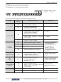
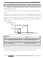
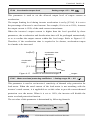
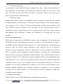
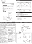
Nameplate of the inverter
On the left side of the inverter body, there is a nameplate marked with the model
and rated parameters of the inverter.
TYPE:
E550-2S0007
SOURCE:
1PH 220V 50/60Hz
OUTPUT:
1.9KVA 5.0A
SERIAL No.:
XXXXXXXXXX
Inverter model
变频器型号
Rated input voltage phase, voltage and frequency
额定输入电压相数、电压及频率
Rated output capacity and current
额定输出容量及电流
Product serial number
产品序列号
Bar code
条形码
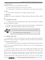
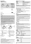
Label on the outer box
TYPE:
E550-2S0007
SOURCE:
1PH 220V 50/60Hz
NET WEIGHT:
KG
GROSS WEIGHT:
KG
VOLUME:
(mm)
SERIAL No.:
XXXXXXXXXX
Inverter model
变频器型号
Rated input voltage phase, voltage and frequency
额定输入电压相数、电压及频率
Net weight
净重
Gross weight
毛重
体积
Volume
序列号
Serial number
Bar code
条形码
E550 Series Universal Low-Power Inverter
Precautions II
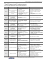
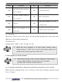
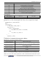
Weight and dimension
Model
Net weight
(KG)
Gross weight
(KG)
Outer box
dimension (mm)
E550-2S0004(B)
E550-2S0007(B)
E550-4T0007(B)
E550-4T0015(B)/E550-2S0015(B)
E550-4T0022(B)/E550-2S0022(B)
E550-4T0030(B)/E550-2S0030(B)
E550-4T0040(B)/E550-2S0040(B)
0.82
0.82
1.54
1.54
1.54
1.82
1.82
1.00
1.00
1.84
1.84
1.84
2.54
2.54
195×115×175
195×115×175
223×135×195
223×135×195
223×135×195
270×160×215
270×160×215
We have strict quality assurance system for the products in terms of manufacturing,
packing and transportation. In case of any careless omission, please contact us or
local agent immediately. We will address the problem at first time.
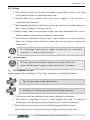
2. Safety precautions
In this manual, the wordings of “Danger” and “Caution” are defined as below.
Danger: Serious damage to the equipment or personal injuries may
be caused if operating without following requirements.
Caution: Moderate injuries or minor injuries of personnel and material
loss may be caused if operating without following requirements.
2.1 Installation
1. The inverter shall not be installed on combustibles
2. The frequency inverter shall not be installed at places with direct sunlight,
3. The frequency inverter of this series shall not be installed in the
environment of explosive gases, for fear of the danger of explosion.
4. No foreign matter is allowed to be dropped into the frequency inverter, for
fear of causing fires or injury.
5. During installation, the frequency inverter shall be installed at the place able
to bear its weight; otherwise, it may fall down or damage properties.
The inverter shall not be dismantled or modified without authorization.
E550 Series Universal Low-Power Inverter
Precautions III
2.2 Wiring
1. Wire diameter shall be selected according to applicable electric code, and
wiring shall be done by qualified technicians.
2. Wiring shall not be started unless the power supply of the inverter is
completely disconnected.
3. The grounding terminal of the inverter must be reliably grounded; otherwise,
there can be a danger of electric shock.
4. Before wiring, make sure the power supply has been disconnected for over 10
minutes; otherwise, there may be a danger of electric shock.
5. The electronic elements in the inverter is quite sensitive to static electricity,
hence no foreign articles shall be placed into the inverter or contact the
main board.
No alternating current power supply is allowed to be connected
onto the U, V, and W of the inverter.
2.3
Maintenance
Wiring, inspection and other maintenance work shall not be
done until the power supply is disconnected for 10 minutes.
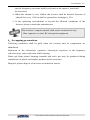
3. Precautions of use
In this manual, the wordings of “Tip” and “Attention” are defined as below:
Tip: To give some useful information.
Attention: To indicate any precautions during operation.
1. The inverter shall be installed in the place with good ventilation.
2. The motor’s temperature can be a little higher than that of industrial
frequency power during operation of the inverter, which is abnormal.
3. With long-term operation at low speed, the operation life of motor
can be affected due to the poorer heat dissipation effect. In this case,
E550 Series Universal Low-Power Inverter
Precautions IV
special frequency converter shall be selected or the motor’s load shall
be decreased.
4. When the altitude is over 1000m, the inverter shall be derated. Increase of
altitude for every 1500 m shall be ground for derating by 10%.
5. If the operating environment is beyond the allowed conditions of the
inverter, please consult the manufacturer.
The inverter’s output terminal shall not be connected to any
filter capacitor or other RC absorption equipment.
4.Scrapping precautions
Following attentions shall be paid when the inverter and its components are
abandoned.
Explosion of the electrolytic capacitor: electrolytic capacitor in the frequency
converter may cause explosion while burning.
Waste gas from plastic burning: harmful and toxic gas may be produced during
combustion of plastic and rubber products of the converter.
Disposal: please dispose of inverters as industrial wastes.
E550 Series Universal Low-Power Inverter
Product Introduction 1
1 Product introduction
1.1 Description of inverter model
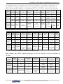
1.2 Model of inverter series
Inverter model
E550-2S0004(B)
E550-2S0007(B)
E550-2S0015(B)
E550-2S0022(B)
E550-2S0030(B)
E550-2S0040(B)
E550-4T0007(B)
E550-4T0015(B)
E550-4T0022(B)
E550-4T0030(B)
E550-4T0040(B)
Rated
capacity
(KVA)
1.1
1.9
2.9
3.8
5.3
6.3
1.6
3.0
3.6
5.0
6.3
Rated output
current
(A)
3.0
5.0
7.5
10.0
14.0
16.5
2.5
4.5
5.5
7.5
9.5
Adaptive motor
power
(KW)
0.4
0.75
1.5
2.2
3.0
4.0
0.75
1.5
2.2
3.0
4.0
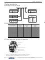
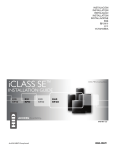
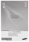
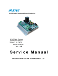
1.3 Product appearance and name of components
Operating
操作面板 panel
Housing
壳体
Control
loop cable inlet
控制回路电缆入口
Main loop cable inlet
主回路电缆入口
Bottom
installation hole
底部安装孔
底部导轨扣
Bottom guide rail fastener
Figure 1-1 Appearance and Part Name of Category I Inverters
Applicable models: E550-2S0004 (B) / E550-2S0007 (B)
E550 Series Universal Low-Power Inverter
Product Introduction 2
操作面板 panel
Operating
操作面板
Operating panel
Housing
壳体
Housing
壳体
Control loop cable
控制回路电缆入口
inlet
控制回路电缆入口
Control loop cable
inlet
Main
loop cable inlet
主回路电缆入口
Main loop cable
主回路电缆入口
Bottom
installation hole
底部安装孔
Bottom
guide rail fastener
底部导轨扣
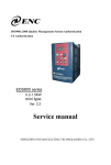
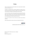
Figure 1-2 Appearance and Component
Name of Category Ⅱ Inverters
Applicable models:
E550-2S0015(B)~E550-2S0022(B)/
E550-4T0007(B)~E550-4T0022(B)
inlet
Bottom
Bottominstallation
installationhole
hole
底部安装孔
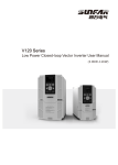
Figure 1-3 Appearance and Component
Name of Category III Inverters
Applicable models:
E550-2S0030(B)~E550-2S0040(B)/
E550-4T0030(B)~E550-4T0040(B)
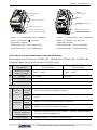
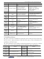
1.4 Product technical indicators and specifications
Power range of E550 series: 2S0004 (B) ~2S0040 (B) /4T0007 (B) ~4T0040 (B).
Input
Technical index and typical function of E550 series
Rated voltage,
Three phase (4T# series)
380V50/60Hz
frequency
Allowed variation
range of voltage
Output
Voltage
Frequency
Single phase (2S# series)
220V50/60Hz
300V ~ 460V
180V ~ 260V
0 ~ 380V
0~220V
0.0~1000Hz
Overload capacity
110%--long term; 150%--1 minute; 180%--2 second
Control mode
VVVF space voltage vector
Control Characteristics
Analog
Frequency terminal
input
Set
resolution Digital
setting
Frequency
precision
0.1% of the maximum output frequency
0.1Hz
Analog
input
Within 0.1% of the maximum output frequency
Digital
input
Within 0.1% of the set output frequency
V/F curve
(Voltage frequency
characteristics )
Torque increase
Reference frequency can be set within 5~1000Hz, and multi-node
V/F curve can be randomly set.
Manual setting: 0.0~20.0% of rated output.
E550 Series Universal Low-Power Inverter
Product Introduction 3
Automatic current
limiting and voltage
limiting
Automatically detect motor’s stator current and voltage and control
it within allowable range according to special algorithm, regardless
of any running process like acceleration, deceleration or static
running.
Under voltage
limiting during
running
Especially for users of low-grid voltage and frequently fluctuating
grid voltage. Even within the voltage range lower than allowable
value, the system can maintain longest running time according to
special algorithm and residual capacity distribution strategy.
Multispeed cont0rol
7-section programmable multispeed control and 5 kinds of running
modes available for selection
Optional built-in PID
controller
Internal integrated optimized PID controller, allowing for simple
closed-loop control.
RS485 communication
and linkage control
Ty p i c a l f u n c t i o n s
Analog input
Frequen
-cy
setting Digital input
Relay and
OC output
Output
signal
Analog
output
SUNFAR user-defined protocol or MODBUS protocol.
DC voltage 0-10V, and DC current 0-20mA (optional)
Operating panel setting, potentiometer setting, RS485 port setting,
UP/DW terminal control, and multiple combined setting with
analog input.
One channel OC output and One channel relay output (TA, TC),
with up to 16 kinds of optional meanings.
One channel 0-10V voltage signal, and upper and lower limit can
be set.
Automatic voltage
regulation running
Three kinds of voltage regulation modes including dynamic, static
and none are available for selection according to different
requirements, so as to achieve most stable running effect.
Setting of acceleration
and deceleration time
0.1~600.0Sec continues setting, and deceleration and acceleration
curve S type and liner mode are optional.
Timer
Running function
Display
Display
of
operation panel
Running
status
Alarm
content
One built-in timer
Setting of upper and lower limiting frequency, REV running
limiting, RS485 communication, and control of progress increase
and decrease of frequency, etc.
Output frequency, output current, output voltage, motor revolution,
set frequency, module temperature, analog input and output and
so on.
The nearest 4 times of fault records, five items of running
parameter records at the time of latest fault trip including, the
output frequency, output current, output voltage, DC voltage and
modular temperature.
Protection/alarm function
Over current, overvoltage, under voltage, overheat, short circuit,
internal memory fault, etc
Surrounding
temperature
Environment
Surrounding
humidity
Surrounding
environment
90% below (no frosting)
-10ºC to +40ºC (no freezing)
Indoor (Free of direct sunlight, corrosion, flammable gas, oil mist
and dusts)
E550 Series Universal Low-Power Inverter
Product Introduction 4
Altitude
Protecting
grade
Cooling
mode
Installation mode
Below 1000m
IP20
Forced air cooling
Rail type /wall-mounted
E550 Series Universal Low-Power Inverter
Inverter Installation
5
2. Inverter installation
2.1 Environmental requirements
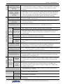
This series of inverters are wall-mounted products and shall be vertically installed
to facilitate air circulation and heat dissipation. Following attentions shall be paid
for selecting installation environments.
1.
2.
3.
4.
5.
6.
The ambient temperature shall be within -10℃-40℃.
High-temperature and humid places shall be avoided, and
the inverter shall be better placed in a place with
humidity lower than 90% and without frosting.
Direct sunshine should be avoided.
The inverter should be away from flammable, explosive
and corrosive gas and liquid.
The environment should be free of dust, floating fibers
and metal particles.
The installation surface should be solid without
ventilation.
The inverter should be away from electromagnetic
interference sources
If you have any special installation requirements, please contact us in advance.
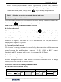
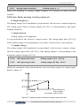
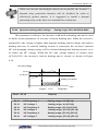
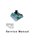
See Figure 2-1-A for installation spacing and distance requirement for single
inverter. Enough space should be leaved around the inverter. For installation of
multiple inverters, baffle plate should be applied between inverters to ensure good
heat dissipation, as shown in Figure 2-1-B.
50mm
50mm以上
b
Inverter
120mm以上
120mm above
风扇排气
Fan exhaust
变
频
器
50mm
50mm以上
b
导流隔板plate
Baffle
Inverter
变
频
器
! WARNING
1.Refer to the instruction manual before installation
and operation.
2.Do not connect AC power to output terminals UVW.
3.Do not remove any cover while applying power
and at least 10min. after disconnecting power.
4.Securely ground(earth) the equipment.
120mm以上
120mm above
Figure 2-1-A Installation Spacing Distance
Figure 2-1-B Installation of Multiple Inverters
E550 Series Universal Low-Power Inverter
Inverter Installation
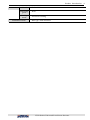
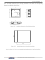
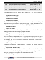
2.2 Installation dimension of inverters
2.2.1 Installation dimension of inverters
H1
H
W
W1
D
E550
Figure 2-2-A
Inverter Installation Dimension 1
Applicable models: E550-2S0004 (B) ~E550-2S0007 (B), shown in Figure 2-2-A
E550
H1
H
W
W1
D
2S0015
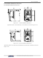
Figure 2-2-B
Inverter Installation Dimension 2
Applicable models: E550-2S0015(B)~2S0040(B)/E550-4T0007(B)~4T0040(B),as shown in
Figure 2-2-B.
E550 Series Universal Low-Power Inverter
6
Inverter Installation
7
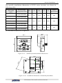
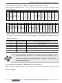
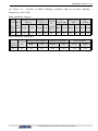
The specific installation dimensions of E550 series inverters are shown in
following table:
Inverter model
(three-phase
380V)
Inverter model
(single-phase 220V)
-
E550-2S0004(B)
-
E550-2S0007(B)
E550-4T0007(B)
-
E550-4T0015(B)
E550-2S0015(B)
E550-4T0022(B)
E550-2S0022(B)
E550-4T0030(B)
E550-2S0030(B)
E550-4T0040(B)
E550-2S0040(B)
W1
W
H1
H
D
Screw
specification
67.5
81.5
132.5
148
134.5
M4
86.5
101.5
147.5
165
154.5
M4
100
110
190
205
169.5
M5
2.2.2 Installation dimensions of optionals
41.1
28.8
60.7
68.7
17.6
Figure 2-2-C Small Keyboard Installation Dimension
36.7
25.5
58.7
62.2
16.4
17.6
20.7
Figure 2-2-D
Installation Dimension of Small Keyboard Base
E550 Series Universal Low-Power Inverter
Inverter Installation
8
Note: Assemble with M3 screws and pay attention to the whole site and opening
dimension within the dotted lines.
85
80
72
21.4
17.3
69
Installation Dimension of Small Keyboard Base
80.5
Figure 2-2-E
69.5
Figure 2-2-F
Opening Dimension of Small Keyboard Base
Note: See Figure 2-2-F for the recommended opening dimension of small keyboard base
E550 Series Universal Low-Power Inverter
Inverter Wiring 9
3. Inverter wiring
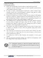
3.1 Wiring precautions
(1)
(2)
(3)
(4)
(5)
(6)
Make sure intermediate circuit breaker is connected between the
frequency inverter and power supply to avoid expanded accident when
the frequency inverter is faulty.
In order to reduce electromagnetic interference, please connect surge
absorber on the coil of electromagnetic contactor, relay and etc. in the
surrounding circuit of the frequency inverter.
Please use shielded wire of above 0.3mm² for the wiring of such analog
signals as frequency setting terminal AI and instrument loop (AO), etc.
The shielding layer shall be connected on the grounding terminal E of
the frequency inverter with wiring length less than 30m.
The stranded wire or shielded wire of above 0.75mm² shall be selected
for the wiring of input and output loop (X1-X4) of relay; and the
shielded layer shall be connected to the common port CM of control
terminals, with wiring length less than 50 m.
The control wire shall be separated from the power line of major loop;
it shall be at a distance of above 10cm for parallel wiring and vertical
for cross wiring.
The connecting wire between the inverter and the motor shall be less than
30m; and when it is longer than 30m, the carrier frequency of the inverter
shall be appropriately reduced.
(7)
All leading wires shall be fully fastened with terminals to ensure good
(8)
The pressurization of all the leading wires shall be in compliance with
the voltage class of the frequency inverter.
contact.
Absorption capacitor or other RC absorbers shall not be
installed at U, V and W output end of the frequency inverter,
as shown in figure 3-1.
E550 Series Universal Low-Power Inverter
Inverter Wiring 10
Motor
电
动机
U
Inverter
变
频器
M
V
W
RC
阻
容absorber
吸收装置
Figure 3-1 Forbidding connecting a RC absorber at the output terminal
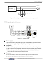
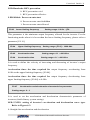
3.2 Wiring of peripheral elements
Braking
resistor
制动电阻
AC Power
ACsupply
电源
PP
PB
U
R/L1
V
S/L2
E550
T
Air switch
空气开关
Contactor
接触器
!
WARNING
1.Ref er t o the instruc ti on manual be fore ins ta llation
a nd ope ra ti on.
2.Do not conne ct AC power to out put te rmina ls U VW.
3.Do not r emove any cove r w hil e appl ying pow er
a nd at le as t 1 0min. afte r disconne cting pow er.
4.Securel y ground(e arth) the equi pme nt.
W
AC reactor
AC 电抗器
E550
电机
Motor
Figure 3-2 Inverter Wiring
Power supply
The inverter shall be provided with power in accordance with specification
of input power supply designated by this operating manual
Air switch
1) When the frequency inverter is maintained or not in use for a long time,
2) the air switch will separate the frequency inverter from the power supply;
3) When the input side of the frequency inverter has failures like short
circuit, the air switch can provide protection.
Contactor
It can conveniently control power-supply and power disconnection of
the inverter, and the power-on and power-off of the motor.
E550 Series Universal Low-Power Inverter
Inverter Wiring 11
AC reactor
1) To promote power factor;
2) To reduce harmonic input of the inverter against the grid;
3) Weaken influenced caused by unbalanced voltage of three-phase
power supply.
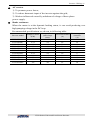
Brake resistance
When the motor is at the dynamic braking status, it can avoid producing over
high pumping voltage in the DC loop.
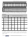
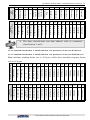
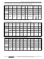
Recommended specifications are shown in following table:
Inverter model
Adaptive motor
(KW)
E550-2S0004
E550-2S0007
E550-2S0015
E550-2S0022
E550-2S0030
E550-2S0040
E550-4T0007
E550-4T0015
E550-4T0022
E550-4T0030
E550-4T0040
0.4
0.75
1.5
2.2
3.0
4.0
0.75
1.5
2.2
3.0
4.0
Wire specification
Electromagnetic
Air circuit breaker
(main loop)
contactor
(A)
2
(mm )
(A)
1.5
16
6
2.5
20
12
2.5
32
18
4.0
32
18
6.0
40
32
6.0
40
32
1.0
10
6
1.5
16
12
2.5
16
12
3.0
20
18
4.0
32
18
E550 Series Universal Low-Power Inverter
Inverter Wiring 12
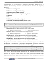
3.3 Basic wiring
Three-phase circuit breaker
Three-phase
三相电源
power supply
三相断路器
×
×
×
Programmable
可编程输入端子
input terminal
Motor
R
S
T
电动机
U
V
W
E
X1
Ta
X2
X3
X4
CM
Tc
M
~
To earth
接大地
Failure alarm output
故障报警输出
PP
To braking resistor
E
外接制动电阻
PB
Auxiliary
DC
24V supply
辅助直流电源
power
AO
Voltmeter
电压表(0~10V)
(0-10V)
GND
Open-circuit
0~10V(0~20mA)
Frequency
setting
频率设定
VS
collector output
OC 开路集电极输出
AI
GND
CM
Figure 3-3 Basic Wiring of Inverter
E550 Series Universal Low-Power Inverter
Inverter Wiring 13
3.4 Wiring of main loop terminal
Category II main loop terminal
Applicable models: E550-2S0004(B)~E550-2S0007(B)
L1
L2
PP
PB
E
U
Symbol
W
V
Function
DC side voltage positive
terminal
Braking resistor can be
connected between PP and PB
To grid single-phase AC 220V
power supply
To three-phase AC 220V motor
Earthing terminal
PP
PB
Earthing
大地
制动电阻
Braking
resistor
L1, L2
Motor
电动机
220Vsupply input
Power
电源输入
U, V, W
E
Category II main loop terminal
Applicable models: E550-2S00015 (B) ~E550-2S0022 (B) & E550-4T00007 (B)
~E550-4T0022 (B)
L1
R
L2
S
T
PP PB
U
V
W
Symbol
E
Function
PP
PB
Braking resistor
制动电阻
单相/三相
Single-phase/three-phase
电源输入
Power
supply input
Earthing
大地
Motor
电动机
L1
R
,
L2
S
,T
U, V, W
E
DC side voltage positive
terminal
Braking resistor can be
connected between PP and PB
To grid single-phase AC 220V
/three-phase 380V power
supply
To three-phase AC
220V/380V motor
Earthing terminal
Category III main loop terminal
Applicable models: E550-2S0030 (B)~E550-2S0040(B) &
E550-4T00030(B)~E550-4T0040(B)
Symbol
PP
PB
L1
R
L2
S
PP
T
E
U
V
W
PB
Braking
resistor
制动电阻
Earthing
大地
单相/三相
Single-phase/three-phase
Power 电源输入
supply input
Motor
电动机
L1 L2
,
,T
R S
U, V, W
E
Function
DC side voltage positive
terminal
Braking resistor can be
connected between PP and PB
To grid single-phase AC 220V
/three-phase 380V power supply
To three-phase AC 220V/380V
motor
Earthing terminal
E550 Series Universal Low-Power Inverter
Inverter Wiring 14
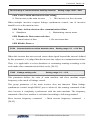
3.5 Wiring of control loop terminal
(1) Diagram of control loop terminal
input
→Voltage/current
jumper terminal
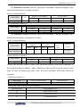
(2) Function description of control loop terminal
Type
Terminal
symbol
VS
Power supply
24V
AI
Analog input
GND
Terminal function
Remarks
Externally providing +10V
(0~20mA) power supply
-
External providing +24V
(0~50mA) power supply
(CM terminal is the power grand).
-
Voltage signal input terminal
(when jumper terminal is
connected to V terminal)
0~10V
Current signal input terminal
(when jumper terminal is connected
to A terminal)
0~20mA
Common port of analog input
signal (VS power grand)
-
X1
Multifunctional input terminal 1
X2
Multifunctional input terminal 2
X3
Multifunctional input terminal 3
X4
Multifunctional input terminal 4
Analog output
AO
Programmable voltage signal
output terminal (external
voltage meter (set by [F1.05]
Voltage signal output
0-10V
OC
output
OC
Programmable open-circuit
collector output, set by
parameter [F1.13]
Maximum load current
150mA and maximum
withstanding voltage
24V.
Programmable
output
TA
TC
TA-TC normally open;
Contact capacity:
When TA-TC is closed, effective
AC 250V, 1A resistive
when parameter [F1.14]
load
selects output.
Control
terminal
Communication
The specific function
of multifunctional
input terminal is to be
set by parameter
[F1.08] – [F1.11],
effective when the
terminal and CM end
is closed.
RS+
485 communication port
-
RS-
485 communication port
-
E550 Series Universal Low-Power Inverter
Operating Panel 15
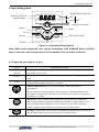
4 Operating panel
运行指示灯
Running
indicator
数码显示
Digital
display
Digital display data unit
数码显示数据单位
RUN
V
sec
Hz
%
A
rmp
MIN
Return
返 回
MAX
面板电位器
Panel potentiometer
移位
Shift
ESC
上 UP
升
Setting
设 置
SET
RUN
STOP
Run,
stop, restore
运行、停止、复位
下
降
Down
Figure 4-1 Operating Panel Sketch
Note: E550 series keyboard port can be compatible with SUNFAR E300 and E310
series, and other series keyboard is not compatible. Do not make confusion.
4.1 Function description of keys
Keys
Function Description
Digital
display
Display the current operating status parameters and setting parameters of
the frequency inverter.
A, Hz, V
Display the measurement unit corresponding to the main digital display
data.
RUN
Operating indicator, indicating the inverter is running, and there is output
voltage at the output terminals U, V and W.
Data modification key. It is used to modify functional code or
parameters.
At the status monitoring mode, if the frequency command channel is at
the digital setting mode ([F0.00]=0), press this key to directly modify the
frequency set value.
ESC
SET
Back key. At the normal monitoring mode, press this key to enter the
non-normal monitoring mode/monitoring parameter inquiry mode to see
the operating status parameters of the inverter. At any other operating
status, separately press this key to back to the previous status.
Set key. Confirm the current status or parameter (parameters are stored in
the internal memorizer) and enter the next function menu.
E550 Series Universal Low-Power Inverter
Operating Panel 16
RUN/STOP command key.
When the command channel selects control panel ([F0.02] =###0), this
key is effective. The key is a trigger key. When the inverter is at the stop
status, press this key to input stop command to stop running. At the
inverter fault status, this key is also used as the fault reset key.
RUN
STOP
Shift key. When modifying data with any data modification key, press this
key to select the data digit to be modified, and the selected digit will flash.
MIN
MAX
Panel potentiometer. When the inverter’s running frequency is set by the
potentiometer on the operating meter (F0.00=3), rotate the potentiometer
knob counterclockwise to decrease running frequency, and rotate it
clockwise to increase running frequency.
4.2 Panel operating method
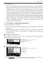
(1) Status parameter inquiry (example)
E550 Series Universal Low-Power Inverter
Operating Panel 17
(2) Parameter inquiry and modification (example)
Normal status monitoring
mode
Display: 45.0
Output frequency
SET
Parameter inquiry
Return
Display: F0.00
Function code
Select
inquired/modified
parameter item
ESC
Parameter inquiry
Display: F0.01
SET
Display: 45.0
Modify parameter
whennecessary
ESC
Parameter modification
Save modified
parameter
Parameter data
Display: 50.0
ESC
SET
Parameter save
Parameter data
Abandon modification
Parameter inquiry
Display: F0.01
Continue modifying other parameters or return
ESC
Function code
Function code
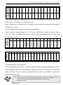
4.3 List of status monitoring parameters
Monitoring
code
d-00
d-01
d-02
d-03
d-04
d-05
d-06
d-07
d-08
d-09
d-10
d-11
d-12
d-13
d-14
d-15
d-16
d-17
Content
Inverter’s current output frequency
Inverter’s current output current
(effective value)
Inverter’s current output voltage
(effective value)
Motor revolution
Voltage at the DC terminal in the inverter
Inverter’s input AC voltage (effective value)
Set frequency
Analog input AI
Running liner speed
Set liner speed
Input terminal status
Module temperature
Analog output AO
Timer value
Reserve
Reserve
Reserve
Reserve
E550 Series Universal Low-Power Inverter
Unit
Hz
A
V
rpm
V
V
Hz
V
ºC
V
Operating Panel 18
d-18
d-19
d-20
d-21
d-22
d-23
d-24
d-25
d-26
d-27
d-28
d-29
d-30
d-31
Reserve
Reserve
Reserve
Reserve
Reserve
First fault record
Second fault record
Third fault record
Forth fault record
Output frequency at the time of recent fault
Output currency at the time of recent fault
Output voltage at the time of recent fault
DC voltage at the time of recent fault
Module temperature at the time of recent fault
Hz
A
V
V
4.4 Simple operation of the inverter
4.4.1 Initial setting
(1) Channel selection for frequency input ([F0.00])
Inverter’s initial setting varies from each other according to different models. When
the parameter is set to 0, the inverter’s frequency setting will be set through the
panel digit.
(2) Selection of running command input channel ([F0.02])
The inverter’s initial setting varies according to different models. When this
parameter is set to [F0.02] =###0, the inverter’s start and stop control will be
completed through
RUN
STOP
key on the operating panel.
4.4.2 Simple running
It is absolutely forbidden to connect the power cord to the
output U, V, W of the frequency inverter.
Three-phase circuit breaker
三相断路器
Three-phase
power
三相电源
supply
×
×
×
Motor
电动机
R
S
T
U
V
W
M
E
Earthing
接大地
Figure 4-2 Simple Running Wiring Diagram
E550 Series Universal Low-Power Inverter
Operating Panel 19
① Connect wires as per Figure 4-2;
② Switch on the power supply after confirming that the wires are connected
correctly, and the inverter will firstly display “P.oFF” and then “0”.
③ Confirm that the frequency setting channel is at the digit setting model ([F0.00]
= 0);
④ It is required to set parameter [F0.12] and [F0.13] according to the rated nameplate
data on the inverter’s dragging motor.
⑤ Press
RUN
STOP
key to start the inverter and the inverter will input 0 frequency,
displaying “0.0”.
⑥ Press Up of
key to increase set frequency, and the output frequency of the
inverter will increase and the motor revolution will also increase.
⑦ Check if the motor run normally. In case of any abnormity, stop running the motor
immediately and disconnect power supply. Do not run the motor until fault cause is
found.
⑧ Press Down on the
⑨ Press
RUN
STOP
key to decrease set frequency.
key again to stop running and cut off the power supply.
The default value of the carrier frequency is fixed (1.5-10 KHz).
If the motor is completely empty-load, slight oscillation may occur
sometimes in the operation under high carrier frequency. At this
time, please reduce the setting value of the carrier frequency.
(Parameter [F0.08]).
E550 Series Universal Low-Power Inverter
Functional Parameter Table 20
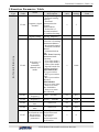
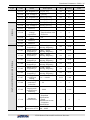
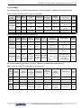
5 Function Parameter Table
Parameter Function
Type
Code
F0.00
F0.01
Basic running parameter group
F0.02
F0.03
F0.04
F0.05
F0.06
F0.07
Setting Range and Minimum Default
Description
unit
setting
0: Digital setting
1: External analog
quantity
2: External
Frequency input communication
1
3
channel
3:Panel
potentiometer
4: Selection of
external terminal
5:Combined setting
0.0Hz ~ Upper
Frequency
0.1
0.0
digital setting limiting frequency
LED Units:
Selection of running
command channel
0: Keyboard control
1: External terminal
control
2: communication
port
LED Tens: Running
command mode
selection
0: Two-line mode 1
Selection of
1: Two-line mode 2
running
2: Three-line mode
1
1000
command
3: Special mode for
channel and
terminal machine
mode
LED Hundreds:
REV prevention
0: REV prevention
void
1: REV prevention
effective
LED Kilobit:
Power-on auto start
0: Power-on auto
start forbidden
1: Power-on auto
start allowed
Lower limiting
0.0Hz ~ [F0.04]
0.1
0.0
frequency
Upper limiting
[F0.03] ~ 1000Hz
0.1
50.0
frequency
Acceleration
0.1 ~ 600.0 Sec
0.1
5.0
time
Name
Deceleration
time
0.1 ~ 600.0 Sec
0: Straight line
Acceleration and acceleration and
deceleration deceleration
characteristic 1: S Curve
parameter
acceleration and
deceleration
0.1
5.0
1
0
E550 Series Universal Low-Power Inverter
Modification
limit
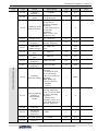
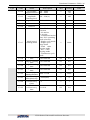
Functional Parameter Table 21
Parameter Function
Type
Code
F0.08
F0.09
F0.10
Setting Range and
Description
Name
Carrier
frequency
Modulation
mode
1.5 ~ 10.0kHz
0: Asynchronous
1: Synchronous
1: Only allowing to
rewrite F0.01
parameter and this
parameter
Parameter write
2: Only allowing to
and protection
rewrite this
parameter
Other values: All
parameters are
F0.11
Torque boost
F0.12
Basic running 5.0Hz ~ Upper
frequency
limiting frequency
F0.13
Maximum
25 ~ 250V/50 ~
output voltage 500V
F0.14
F0.15
F0.16
Jog acceleration
time
Jog deceleration
time
FWD jog
frequency
REV jog
frequency
0.0 ~ 20.0 (%)
Minimum Default
unit
setting
0.1
8.0
1
0
1
0
0.1
6.0
0.1
50.0
1
220/
440
0.1~ 600.0 S
0.1
5.0
0.1~ 600.0 S
0.1
5.0
0.0Hz~[F0.04]
0.1
10.0
0.0Hz~[F0.04]
0.1
10.0
F0.18
LED Units: running
direction
0: Consistent with
the set direction
Auxiliary
1: Reverse to the set
function setting direction
LED Tens: Jog
priority selection
0: Highest
1: Lowest
1
0000
F0.19
0: Output lower
limiting frequency
when it is lower than
Lower limiting
the lower limiting
frequency
frequency
functioning
1: Output zero
mode
frequency when it is
lower than the lower
limiting frequency
1
0
1
0
0.1
5.0
F0.17
Basic running parameter group
F0.20
Reserve
F0.21
Parameter
protection
password
F0.22
F0.23
0~9999
UP/DW speed 0.1~50.0Hz
Reserve
E550 Series Universal Low-Power Inverter
Modification
limit
×
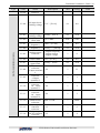
Functional Parameter Table 22
Parameter Function
Type
Code
F0.24
F1.00
F1.01
F1.02
F1.03
F1.04
Input and output parameter group
F1.05
F1.06
F1.07
F1.08
F1.09
F1.10
F1.11
F1.12
F1.13
F1.14
Setting Range and
Description
Name
Minimum Default
unit
setting
Modification
limit
Reserve
AI input lower
0.0 V ~ [F1.01]
limiting voltage
AI input upper
limiting voltage
AI input
filter time
Minimum set
frequency
Maximum set
frequency
0.1
0.0
[F1.00] ~ 10.0 V
0.1
10.0
0.01~1.00S
0.01
0.01
0.0Hz ~ [F1.04]
0.1
0.0
[F1.03] ~ [F0.04]
0.1
50.0
1
0
0: output frequency
Analog output
1: output current
selection
2: output voltage
AO output
0.0V ~ [F1.07]
lower limit
AO output
[F1.06] ~ 10.0V
upper limit
Function
selection
0~29
of input terminal
1
Function
selection
0~29
of input
terminal 2
Function
selection
0~29
Of input
terminal 3
Function
selection
0~29
Of input
terminal 4
Input channel
characteristic 0000~1111H
selection
OC output
function
0~15
selection
Relay output
TA/TC function 0~15
selection
0.1
0.0
0.1
10.0
1
11
×
1
1
×
1
2
×
1
3
1
0000
1
0
1
8
E550 Series Universal Low-Power Inverter
Functional Parameter Table 23
Parameter Function
Type
Code
F1.15
F1.16
F1.17
F1.18
Input output parameter group
F1.19
F1.20
F1.21
F1.22
F1.23
F1.24
F1.25
F1.26
F1.27
Name
OC and relay
output
characteristic
selection
Relay action
delay
Frequency
reaching
detecting
amplitude
FDT
( frequency
level) setting
FDT output
delay time
Overload alarm
level
Overload alarm
delay time
Setting Range and
Description
LED Units: OC
output selection
0: OC output
positive
characteristics
1: OC output
negative
characteristics
LED Tens: relay
output selection
0: relay output
positive
characteristics
(normally open)
1: relay output
negative
characteristics
(normally closed)
Minimum Default
unit
setting
1
0000
0.0S~5.0S
0.1
0
0.0 ~ 20.0Hz
0.1
5.0
0.0 ~[F0.04]
0.1
10.0
0.0 ~ 5.0Sec
0.1
2.0
50 ~200(%)
1
110
0.1
2.0
1
10
0.0 ~ 60.0 Sec
Reserve
Reserve
Batter number
of terminal 1~100
machine
Designated
1~[F1.26]
counting value
Final counting
[F1.25]~60000
value
1
5
1
100
Reserve
E550 Series Universal Low-Power Inverter
Modification
limit
×
×
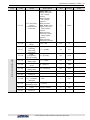
Functional Parameter Table 24
Parameter Function
Type
Code
F1.28
F1.29
F1.31
F2.00
F2.01
F2.02
Auxiliary running parameter group
F2.03
F2.04
F2.05
F2.06
F2.07
F2.08
Name
Frequency
input channel
combination
Setting Range and Minimum Default
Description
unit
setting
0: External voltage +
panel potentiometer
1: External
voltage+panel
potentiometer +
Digital setting
2:Communication +
external voltage
3: Communication
+ external voltage +
panel potentiometer
4:Communication +
digital-panel
potentiometer
5:Communication 1
0
external voltage
6:Communication +
external voltage panel potentiometer
7:External voltage
+ digital - panel
potentiometer
8:Panel
potentiometer Digital setting
9:UP/DW+
External voltage
10: UP/DW + panel
potentiometer +
external voltage
Modification
limit
Reserve
Start frequency 0.0 ~ 50.0Hz
Start frequency
0.0 ~ 20.0 Sec
duration
0: Deceleration stop
Stop mode
1: Free stop
Stop DC braking
0.0~[F0.04]
frequency
Stop DC braking
current
Stop DC braking
time
Acceleration
torque level
Motor overload
protecting
coefficient
Dynamic
braking
Initial
voltage (1)
F2.09
Reserve
F2.10
Reserve
0.1
1.0
0.1
0.0
1
0
0.1
3.0
0 ~ 100(%)
1
10
0.0 ~ 20.0 Sec
1
0.0
110 ~ 200(%)
1
170
50 ~ 110(%)
1
110
300 ~ 400V/600 ~
800V
1
370
740
E550 Series Universal Low-Power Inverter
×
×
Functional Parameter Table 25
Parameter Function
Type
Code
F2.11
F2.12
F2.13
F2.14
F2.15
Setting Range and
Description
Name
V/F frequency 1 0.0~[F2.13]
V/F voltage 1
V/F voltage 2
Continued
V/F voltage 3
F2.17
Reserve
F2.19
F2.20
[F2.12]~[F2.16]
Automatic
voltage
regulation
Pairs of motor
poles
0.1
1
0
0.1
0.0
1
0
0.0
[F2.14]~[F0.13]
1
0
0: Void
1: Deceleration void
2: Effective
1
0
1~16
1
2
0.1
35.0
0.1
15.0
0.1
3.0
Reserve
Multispeed and senior running parameter group
F2.21
Reserve
F3.00
Multi-speed
frequency 1
0.0Hz ~ Upper
limiting frequency
F3.01
Multi-speed
frequency 2
F3.02
Multi-speed
frequency 3
0.0Hz ~ upper
limiting frequency
0.0Hz ~ upper
limiting frequency
F3.03
Multi-speed
frequency 4
0.0Hz ~ upper
limiting frequency
0.1
20.0
F3.04
Multi-speed
frequency 5
0.0Hz ~ upper
limiting frequency
0.1
25.0
F3.05
Multi-speed
frequency 6
0.0 Hz~ upper
limiting frequency
0.0 Hz~ upper
limiting frequency
0.1
30.0
0.1
35.0
0.01
1.00
0 ~ 22
1
0
0 ~ 9999
1
1700
1
0
1
200/
400
F3.06
F3.07
F3.08
F3.09
F3.10
F3.11
Modification
limit
0.0
0.1
V/F frequency 3 [F2.13]~[F0.12]
F2.16
F2.18
0~[F2.14]
V/F frequency 2 [F2.11]~[F2.15]
Minimum Default
unit
setting
Multi-speed
frequency 7
Liner speed
coefficient
setting
Monitoring
parameter
selection
Parameter
inquiry and
modification
authority
0.01 ~ 100.00
0: No action
1: Standard
initialization
2: Fault
elimination record
3: Complete
initialization
Under voltage 180 ~ 230V /
protection level 360 ~ 460V
Parameter
initialization
E550 Series Universal Low-Power Inverter
×
Functional Parameter Table 26
Parameter Function
Type
Code
F3.12
F3.13
F3.14
Setting Range and
Description
Overvoltage 350 ~ 400V /
suppression level 700 ~ 800V
Current
amplitude
150 ~ 250(%)
limiting level
Name
Program version 1200 ~ 1299
F3.15
Reserve
F3.16
Reserve
F3.17
F3.18
F3.19
F3.20
F3.21
F3.22
F3.23
F3.24
F3.25
Units: PLC action
selection
0: No action
1: Action
2: Conditional action
Tens: PLC operating
mode selection
Multi-speed 0: Single cycle mode
running mode 1: Single cycle
stop mode
2: Final value
keeping mode
3: Set value
keeping mode
4: Continuous cycle
mode
Stage 1 running
0.0S~6000.0S
time
Stage 2 running
0.0S~6000.0S
time
Stage 3 running
0.0S~6000.0S
time
Stage 4 running
time
PLC multi-speed
running direction
PLC running
scheduled stop
Fault
self-recovery
times
Fault
self-recovery
time
0.0S~6000.0S
Minimum Default
unit
setting
360/
1
720
1
180
1
1200
1
0000
0.1
0.0
0.1
0.0
0.1
0.0
0.1
0.0
0000~1111H
1
0000
0~9999(min)
1
0
0~5
1
3
0.1
2.0
0.0~60.0
E550 Series Universal Low-Power Inverter
Modification
limit
Functional Parameter Table 27
Parameter Function
Type
Code
F3.26
F3.27
F3.28
F3.29
F3.30
F3.31
F3.32
F3.34
parameter group
F4.00
Setting Range and
Description
LED Units:
function setting
0: Swing frequency
function closed
1: Swing frequency
function effective
2: Swing frequency
Swing frequency
function
running setting
conditionally
effective
LED Tens: Center
frequency setting
0: Digital setting
1: Frequency
channel selection
Swing frequency
0.0~50.0%
amplitude
Kick frequency
0.0~80.0%
amplitude
Name
Triangular wave
0.1~300.0 S
descending time
Triangular wave
0.1~300.0 S
ascending time
Swing frequency
Center
0.0~[F0.04]
frequency
setting
Minimum Default
unit
setting
1
0000
0.1
10.0
0.1
0
0.1
1.0
0.1
1.0
0.1
0.0
1
0114
Modification
limit
Reserve
LED Units: Baud
rate selection
0: Reserve 1: 1200
bps
2: 2400 bps 3: 4800
bps
4: 9600 bps
5: 19200 bps
LED Tens: Data
format selection
Communication 0: No check
1: Even parity check
setting
2: Odd parity check
LED Hundreds:
protocol selection
0: SUNFAR
self-defined protocol
1: MODBUS
communication
protocol
LED Kilobit:
Reserve
F4.01
Local address 0 ~ 30
1
1
F4.02
Local response
0 ~ 1000ms
delay
1
5
E550 Series Universal Low-Power Inverter
×
Functional Parameter Table 28
Parameter Function
Type
Code
F4.03
F4.04
F4.05
Setting Range and Minimum Default
Description
unit
setting
LED Units: Inverter
main/slave setting
0: This inverter is a
slave machine
1: This inverter is a
main machine
LED Tens: Selection
of action after
communication failure
Setting of
communication 0: Stop
1
0010
1: Maintaining
auxiliary
function (1)
current status
LED Hundreds:
Data return
selection
0: Data normal
return
1: No data return
LED Kilobit:
Reserve
Communication
overtime detection 0.1 ~ 10.0 Sec
0.1
1.0
time(1)
Linkage setting
0.1 ~ 10.0
0.1
1.0
ratio (1)
Name
F4.06
F4.10
Reserve
F5.00
PID function
selection
F5.01
F5.02
F5.03
0: PID closed
1: PID enabled
0: PID Digital
setting
PID set channel
1: frequency input
channel setting
PID digital
0.0%~100.0%
setting
Units:
0: Void
PID feed
forward
1: Feed forward
enabling
setting ( frequency
input channel )
PID
1
0
1
0
0.1
0.0
1
0
1.000
F5.04
Reserve
F5.05
PID feedback
correction
0~2.000
0.001
F5.06
Ratio grain
0.0~10.0
0.1
1.0
F5.07
Integral time
0.01~10.00
0.01
0.20
F5.08
F5.09
F5.10
F5.11
Derivative time 0.0~10.00
PID adjustment
0.0~100.0%
frequency range
Breakage
0.0~50.0%
detection value
Breakage
detection delay 0.1~10.0Sec
time
0.01
0.0
0.1
100.0
0.1
5.0
0.1
5.0
E550 Series Universal Low-Power Inverter
Modification
limit
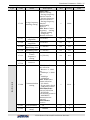
Functional Parameter Table 29
Parameter Function
Type
Code
F5.12
F5.22
F6.00
Setting Range and
Description
Name
Minimum Default
unit
setting
Reserve
Cutting function
0: Drag 1: Cut
selection
1
0
F6.01
Cutting length 0.100~2.000
0.001
0.700
F6.02
Correction of
liner speed
coefficient
0.100~10.000
0.001
1.000
Special function
F6.03
Start delay
0.01~10.00
0.01
3.00
F6.04
Stop delay
0.01~10.00
0.01
4.00
F6.05
Reserve
F6.06
F6.07
F6.08
F6.09
F6.10
F6.11
Modification
limit
Liner cutting
0~2
operating mode
1
0
0~60.0S
0.1
5.0
Backward time 0~60.0S
0.1
4.0
1
99
1
98
1
120
Forward time
High-frequency
relay
[F6.10]~100%
Start frequency
High-frequency
relay
0~[F6.09]
Disconnection
frequency 1
High-frequency
relay
100~200%
Disconnection
frequency 2
Note: (1) E550 series standard model does not has this function, and only some
derived models have such function.
E550 Series Universal Low-Power Inverter
Functional Details 30
6 Function details
6.1 Basic running parameter group
F0.00 Selection of frequency input channel/mode
Setting range: 0 ~ 5
It is used to select setting channel/mode of inverter’s running frequency.
0: Digital setting
The inverter’s set frequency is set by parameter [F0.01].
1: External analog quantity
The running frequency is set by external input voltage signal (0~10V) or current
signal (0~20mA); for relevant characteristics, please refer to parameter [F1.00]
and [F1.01].
2: External communication
To receive frequency setting commands of upper computer or main inverter
through serial RS485 port.
3: panel potentiometer
The running frequency is set by the potentiometer on the operating panel.
4: External terminal selection
The frequency input channel
is confirmed by external multifunctional terminal
(the selection of functional terminals is confirmed by the parameter [F1.08] ~
[F1.11]).
Frequency setting
channel selection 2
Frequency setting
channel selection 1
0
0
0
1
1
0
1
1
Frequency setting channel
Digital setting
External input signal
(0~10V/0~20mA)
RS485 port
panel potentiometer
Note: It is “1” when the terminal and CM is engaged.
5: Combined setting
It is selected by [F1.28] group parameters.
F0.01 Frequency digital setting Setting range: 0.0 Hz ~upper limiting frequency
E550 Series Universal Low-Power Inverter
Functional Details 31
When frequency input channel selects digital setting ([F0.00] = 0), inverter’s
output frequency is determined by this value. When the operating panel is at the
normal monitoring status, simply press
F0.02
key to modify this parameter.
Selection of running command channel and mode
Setting range:
0000 ~ 1132
This functional parameter is used to select inverter’s running command channel and
functions of
RUN
STOP
key (fratile decimal system setting)
LED Units: running command channel selection
0: Keyboard control
The inverter’s running command is controlled by
RUN
STOP
key on the keyboard. In
this mode, the status of external control terminal X1~X4 (FWD running function)
can influence inverter’s output phase sequence. When the external terminals
X1~X4 (FWD running function) is connected to CM, the inverter’s output phase
sequence is negative, and when X1~X4 is disconnected with Cm, the inverter’s
output phase sequence is positive.
1: External terminal control
The inverter’s running command is controlled by the connection and disconnection
status between the multifunctional terminals X1~X4 (FWD or REV control
function) and CM terminal, and its mode is determined by LED tens.
2: Serial communication port
Inverter’s running command receives commands of upper commuter or main
inverter through serial port. When the local inverter is set as the slave in linkage
control, this mode should be selected as well.
LED Tens: selection of running command mode
0: Two-line mode1 (default mode)
command
Terminal
status
Stop command
FEW command
REV command
FW
FWD
FWD
FWD
REV
REV
REV
REV
CM
CM
CM
CM
E550 Series Universal Low-Power Inverter
Functional Details 32
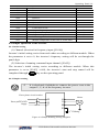
Two-line mode requires selecting one input terminal X1~X4 as forward control
temrinal FWD and the other input terminal X1~X4 as reverse control terminal
REV (refer to parameter [F1.08]~[F1.11]).
1: Two-line mode 2
command
Stop
Terminal
status
Running
FWD
REV
FWD
FWD
REV
REV
CM
CM
CM
CM
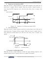
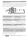
2: Three-line mode
Three-line control mode requires selecting one input terminal (X1~X4) as forward
control terminal FWD, one input terminal (X1~X4) as three-line running control
terminal SW1, and one input terminal (X1~X4) as reverse control model REV
(refer to parameter [F1.08]~[F1.11]). Parameter [F1.08]~[F1.11] is used to select
any one from input terminals X1-X4.
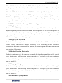
Switch function is described as below:
1. SW1 (three-line running control terminal) -inverter stop trigger switch
2. SW2 (FWD) - FEW trigger switch
3. SW3 (REV) - REV trigger switch
Output输出
frequency
频率
SW1
X?
SW2
FWD
时间
Time
SW3
REV
CM
SW1
SW2
Figure 6-1 Wiring Diagram
in Three-line Control Mode
SW3
Figure
6-2 Frequency Output
Diagram in Three-line Control
Mode
3: Special mode for terminal machine:
This function is only applicable to special occasions such as terminal machine. X1
is used as the approach switch counting and stop signal, and X2 is start signal.
E550 Series Universal Low-Power Inverter
Functional Details 33
LED Hundreds: REV prevention
0: REV prevention void
1: REV prevention effective
LED Kilobit: Power-on auto start
0: Power-on auto start forbidden
1: Power-on auto start allowed
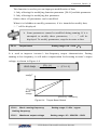
F0.03 Lower limiting frequency
Setting range: 0.0 Hz ~ [F0.
This parameter is the minimum output frequency allowed for the inverter. For the
functioning mode when it is lower than the lower limiting frequency, please refer to
parameter [F0.19].
F0.04
Upper limiting frequency Setting range: [F0.3] ~ 1000.0Hz
F0.05
Acceleration time
F0.06
Acceleration time
Setting range: 0.1 ~ 600.0Sec
Setting range: 0.1 ~ 600.0Sec
It is used to define the velocity of increasing and decreasing of inverter’s output
frequency.
Acceleration time: the time required for output frequency accelerating from
0.0Hz to the upper limiting frequency [F0.04].
Acceleration time: the time required for output frequency decelerating from
upper limiting frequency [F0.04] to 0.0Hz.
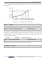
F0.07
Acceleration and deceleration characteristics parameter
Setting range: 0 ~ 1
It is used to set the acceleration and deceleration characteristic parameter of
inverters (fratile binary system setting).
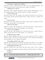
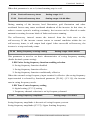
LED UNITS: setting of inverter’s acceleration and deceleration curve type.
Refer to Figure 6-3.
0: Straight line acceleration and deceleration
E550 Series Universal Low-Power Inverter
Functional Details 34
The inverter’s output frequency increases or decreases at fixed speed. For most loads, this
mode can be selected.
1: S curve acceleration and deceleration
The inverter’s output frequency increases or decreases at varying speed. This function is
mainly to reduce noise and ventilation at acceleration and deceleration and reduce load impact
at start and stop.
Output
输出频率(Hz)
frequency
Straight
line
直线
Curve
S 曲线
Curve
Time
时间(Sec)
Figure 6-3 Acceleration and Deceleration Curve
F0.08
Carrier frequency
Setting range: 1.5 ~ 10.0 KHz
This parameter is to determine the switch frequency of inverter’s internal
power module.
The carrier frequency mainly influences the audio noise and heat effect during
running. When mute running is required, it is applicable to appropriately increase
the value of the carrier frequency, but the maximum load allowable for the inverter
may be somewhat reduced, accompanied by somewhat increase of interference of
the inverter to the outside world. For the circumstances where the motor wire is too
long, it may lead to leaking current between motor wires and between the wire and
the ground. When the ambient temperature is too high and the motor load is too
high, or the inverter is failed due to above reasons, it is suggested to appropriately
decrease the carrier frequency to improve thermal characteristics of the inverter.
F0.09
Modulation mode
Setting range: 0 ~ 1
This function is for selection of modulation mode.
0: Asynchronous modulation mode.
1: Synchronous modulation mode.
F0.10
Parameter write protection
Setting range:0 ~ 9999
E550 Series Universal Low-Power Inverter
Functional Details 35
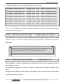
This function is used to prevent improper modification of data.
1: Only allowing for modifying function parameter [F0.01] and this parameter.
2: Only allowing for modifying this parameter.
Other values: all parameters can be modified.
When it is forbidden to modify parameters, if it is intended to modify data,
“- -” will be displayed.
¾ Some parameters cannot be modified during running. If it is
attempted to modify these parameters, “ - - ” will be
displayed. To modify parameters, stop the inverter at first.
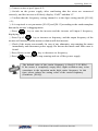
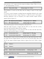
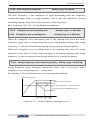
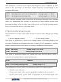
F0.11
Setting range: 0.0 ~ 20.0(%)
Torque boost
It is used to improve inverter’s low-frequency torque characteristics. During
running at low frequency, it will make compensation for boosting inverter’s output
voltage, as shown in Figure 6-4.
Boost
提 升 voltage
电压 =
[F 0 .11 ]
100
× [F 0 .1 3 ]
电压
Voltage
[F0.13]
[F0.11]
Boost
提升
voltage
电压
[F0.12]
频率
Frequency
Figure 6-4 Torque Boost Sketch
F0.12
Basic running frequency
Setting range: 5. 0Hz ~ upper
limiting frequency
F0.13
Maximum output voltage
Setting range: 25 ~ 250V/50 ~ 500V
E550 Series Universal Low-Power Inverter
Functional Details 36
The basic running frequency is the minimum frequency at the maximum voltage of
inverter output. It is generally the motor’s rated frequency.
The maximum output voltage is the output voltage corresponding to the inverter
output basic running frequency, and it is the motor’s rated voltage.
The two items of function parameters need to be set according to motor parameter,
and do not need any modification unless in special cases.
F0.14
Job acceleration time
Setting range: 0.1 ~600.0Sec
F0.15
Job deceleration time
Setting range: 0.1 ~600.0Sec
The transit acceleration and deceleration time between initial running frequency
and jog frequency.
F0.16
FWD jog frequency
Setting range: 0.0Hz ~[F0.04]
F0.17
REV jog frequency
Setting range: 0.0Hz~[F0.04]
Jog running is a special running mode of the inverter. Within the effect period of
jog signals, the inverter runs at the frequency set by this parameter.
No matter the inverter is initially stopped or running, it can receive jog signals.
F0.18
Setting of auxiliary functions
Setting range: 0000 ~ 0011
LED UNITS: Running direction
0: Consistent with the set direction
1: Reverse with the set direction
LED Tens: Jog priority selection
0: Jog priority highest
1. Jog priority lowest
If the jog priority is set to the highest, the pripirty of each freqeuncy source
is as below:
Priority level
Priority
Set frequency source
High
1
Jog frequency (jog running effective)
2
External terminal selection multi-speed frequency
3
Selection of frequency setting channel
([F0.00] parameter)
Low
E550 Series Universal Low-Power Inverter
Functional Details 37
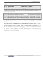
F0.19 Lower limiting frequency functioning mode
Setting range: 0000 ~ 0001
0: Output lower limiting frequency [F0.03] when it is lower than the lower
limiting frequency [F0.03]
1: Output zero frequency when it is lower than the lower limiting frequency
[F0.03]
This parameter is used to set hysteresis to avoid fluctuation around the set
frequency zero point. When the set frequency is lower than f(f=lower limiting
frequency -2Hz), the inverter runs at zero frequency. When the set frequency is
higher than the lower limiting frequency, the inverter runs at the set frequency.
Refer to Figure 6-5.
Actual set
frequency
实际设定频率
F[0.04]
F[0.03]
2Hz
F[0.04] Original
set frequency
原始设定频率
Figure 6-5 Sketch of the Function of Lower limiting frequency
F0.20
Reserve
F0.21
Parameter password protection
Setting range: 0000 ~ 9999
F0.22
UP/DW speed
Setting range: 0.1~50.0Hz
When [F0.00]=5, [F1.28]=9 or 10, and input terminal selects UP or DW function,
frequency can be set through external terminals. This parameter is used to set the
increasing and decreasing speed of the frequency set by external terminal.
E550 Series Universal Low-Power Inverter
Functional Details 38
6.2 analog input output parameter group
The function parameter group [F1.00] ~ [F1.01 defines the
upper and lower limit of external input signal as the frequency
setting signal. E550 series inverters allow for inputting analog
voltage signal and analog current signal; the analog current
signal 0-20mA is corresponding to the voltage signal 0-10V.
F1.00
AI input lower limiting voltage
Setting range: 0.0V ~ [F1.01]
F1.01
AI input upper limiting voltage
Setting range: [F1.00] ~ 10.0 V
[F1.00] and [F1.01] defines AI range of analog input channel, which shall be set according
to actual conditions of access signal.
F1.02
AI input filter time
Setting range: 0.01 ~ 1.00Sec
When external analog input quantity is subject to filter processing to effectively
eliminate interfering signals, if it is set to large value, the interfering capability is
strong but it will slow down response speed to setting signals.
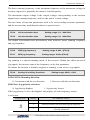
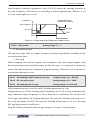
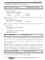
F1.03
Minimum set frequency
Setting range: 0.0Hz ~ [F1.04]
F1.04
Maximum set frequency
Setting range: [F1.03] ~ [F0.04]
The corresponding relationship between the analog input quantity and set
frequency is shown in Figure 6-6.
频率
Frequency
输出频率
Output
frequency
[F1. 04]
[F1. 03]
[F1.00]
[F1.01]
电压
Voltage
Figure 6-6 Corresponding relationship sketch of analog
input quantity and set frequency
E550 Series Universal Low-Power Inverter
Functional Details 39
F1.05
Analog output selection
Setting range: 0 ~ 2
Select the meaning of analog output terminal AO (setting of fratile decimal
system).
LED Units: Define meaning of analog output AO
0: output frequency
The analog output (AO) amplitude is proportional to the inverter’s output frequency.
The setting upper limit of analog output ([F1.07]) is corresponding to the upper
limiting frequency.
1: output current
Analog output (AO) amplitude
It is proportional to the inverter’s output current. The setting upper limit ([F1.07])
of the analog output is corresponding to two times of the inverter’s rated current.
2: Output voltage
The analog output (AO) amplitude is proportional to the inverter’s output voltage.
And the setting upper limit ([F1.07]) of the analog output is corresponding to the
maximum output voltage ([F0.13]).
F1.06
AO output lower limit
Setting range: 0.0 V ~ [F1.07]
F1.07
AO output upper limit
Setting range: [F1.06] ~ 10.0 V
Define the maximum value and minimum value of analog output AO output signal.
Refer to figure 6-7.
AO
[F1.07]
[F1.06]
0
1
2
Upper limiting上限频率
frequency
Output
frequency
输出 频率
Rated current
Output
voltage
额定 电流
输出 电流
Max./rated
voltage
current
最大 /额定
电压 Output
输出 电压
Figure 6-7 Analog output content of analog output terminal
E550 Series Universal Low-Power Inverter
Functional Details 40
F1.08
Function selection for input terminal 1
Setting range: 0 ~ 29
F1.09
Function selection for input terminal 2
Setting range: 0 ~ 29
F1.10
Function selection for input terminal 3
Setting range: 0 ~ 29
F1.11
Function selection for input terminal 4
Setting range: 0 ~ 29
Function definition of switch quantity input terminal X1~X4, which is described
as below:
0: control terminal in idle
1: Multi-speed control 1
2: Multi-speed control 2
3: Multi-speed control 3
The combination of multi-speed control terminals can be used to select multi-speed
output frequency. The frequency setting at each stage is to be determined by the
multi-speed control parameter functional group ([F3.00]~[F3.06]).
4: FWD jog control
5: REV jog control
When the external terminal of running command channel selection is effective, this
parameter can define the input terminal of external jog signals.
6: Frequency set channel selection 1
7: Frequency set channel selection 2
When the frequency input channel is set to be external terminal selection (F0.00=4),
the frequency set channel of the inverter will be determined by the status of these
two terminals, and for its corresponding relationship, please refer to description of
parameter [F0.00].
8: Free stop control
If terminal corresponding to this parameter is engaged, the inverter will lock
output.
9: Three-line running control
When the running command terminal combination mode is set to three-line mode,
the external terminal defined by this parameter is inverter stop trigger switch. See
functional code [F0.02] for the three-line control mode in details.
10: DC braking control
E550 Series Universal Low-Power Inverter
Functional Details 41
At the inverter stop status, if the terminal defined by this parameter is engaged,
when the output frequency is lower than the DC braking initial frequency, the DC
braking function will be enabled until the terminal is disconnected. See description
of [F2.03] ~[F2.05] for relevant parameters of DC braking.
11: FWD control
12: REV control
13: Fault reset
When the inverter is at the faulty status, engaging the terminal set by parameter can
clear inverter’s fault.
14: Reserve
15: Reserve
16: External fault input
When the terminal set by this parameter is engaged, it indicates that the external
equipment is faulty. At this time, in order to ensure safety of the equipment, the
inverter will lock the input and displays the external fault signal Fu.16.
17: Disconnection input
When the terminal set by this parameter is engaged, it indicates disconnection fault
of external equipments. At this time, in order to guarantee equipment safety, the
inverter will lock output, and displays the external fault signal Fu.17.
18: PLC effective
When the programmable PLC running condition [F3.17] is selected to be effective,
the external terminal defined by this parameter can enable effecting and cut-off of
PLC operation.
19: Swing frequency running effective
When the swinging frequency function condition is selected to be effective ([F3.26]
=XXX1), the external terminal defined by this parameter can enable effecting and
cut-off of swing frequency running.
20: UP
21: DW
The running frequency of the inverter can be set through external terminals, hence
allowing for remote frequency setting. When the terminal is effective, the set
frequency increases or decreases at set speed. When the terminal is void, the set
frequency is maintained unchanged. When the two terminals are effective
E550 Series Universal Low-Power Inverter
Functional Details 42
simultaneously, the set frequency is maintained unchanged. When the UP is
effective, the frequency increases and when DW is effective, the frequency
decreases.
22: Internal counting clock
23: Internal counting clock clearing
24: Reciprocating running effective
25: Terminal machine running battering effective
26: Reserve
27: Reserve
28: Splitting machine infrared signal
29: Splitting machine approaching switch signal
F1.12
Selection of input channel characteristics Setting range: 0000~ 1111H
It is used to select characteristics of external digital input:
LED UNITS: Define characteristics of X1 input channel
0: positive characteristics
1: negative characteristics
LED Tens: Define characteristics of X2 input channel
0: positive characteristic
1: negative characteristic
LED Hundreds: Define characteristics of X3 input channel
0: positive characteristic
1: negative characteristic
LED Kilobits: Define characteristics of X4 input channel
0: positive characteristic
1: negative characteristic
The positive characteristic is effective when the terminal is engaged and void when
the terminal is disconnected. The negative characteristic is effective when the
terminal is disconnected and void when the terminal is engaged.
F1.13
Output terminal OC function selection
Setting range: 0 ~ 15
F1.14
Relay output TA/TC function selection
Setting range: 0 ~ 15
It is used to define the contents indicated by the collector open-circuit output
terminal OC and relay output contact. See Figure 6-8 for the internal wiring
diagram of the collector open-circuit output terminal. When the function is set to be
E550 Series Universal Low-Power Inverter
Functional Details 43
effective, the output is at low level, and when the function is void, the output is at
the high-resistance status.
Relay contact output: when the output function is set to be effective, the normally
open contact TA-TC is connected.
D
R
1
2
Figure 6-8 internal circuit of OC output terminal
For connecting external inductive elements (e.g. relay coil),
freewheel diode D must to be connected in parallel.
0: Inverter is running
When the inverter is running, it outputs effective signals, and when the inverter is
at stop, it outputs void signals.
1: Frequency reaching
When the inverter’s output frequency is approaching the set frequency within
certain range (which is defined by parameter [F1.17]), it outputs effective signals,
otherwise, it outputs void signals.
Port output
端口输出
Resistor
Resistor
高阻
高阻
[F1.17]
Frequency
频率
Set frequency
设定频率
Output frequency
输出频率
Output
输出频率frequency
Time
时间
Figure 6-9 Frequency reaching signal
E550 Series Universal Low-Power Inverter
Functional Details 44
2: Frequency level detection (FDT)
When the inverter’s output frequency exceeds FDT frequency level, after the set
delay time, it outputs effective signals. When the inverter’s output frequency is
lower than the FDT frequency level, after the same delay time, it outputs void
signals.
Output 输出端口
terminal
High高resistor
阻
Frequency
频率
High
高resistor
阻
Output frequency
输出频率
[F1.18]
FDT
FDT level
水平
[F1.19]
Figure 6-10
t
[F1.19]
Frequency Level Detection Signal (FDT)
3: Overload detection
When the inverter’s output current exceeds the overload alarm level, after the set
alarm delay time, it outputs effective signals. When the inverter’s output current is
lower than the overload alarm level, after the same delay time, it outputs void
signals.
Out put
Alarm level
报 警水平
[F1. 20]
端口
输出
Port
output
High 高
Resistor
阻
[F 1.2 1]
High
高阻
Resistor
[F1 .2 1]
时间
Time
Figure 6-11 Overload Alarm
4: Frequency reaching upper limit
When the inverter’s output frequency reaches the upper limiting frequency, this
terminal outputs effective signals; otherwise, it outputs void signals.
E550 Series Universal Low-Power Inverter
Functional Details 45
5: Frequency reaching lower limiting
When the inverter’s output frequency reaches the lower limiting frequency, this
terminal outputs effective signals; otherwise, it outputs void signals.
6: Running at zero speed
When the inverter’s running command is effective and the output frequency is at 0,
this terminal outputs effective signals; otherwise, it outputs void signals.
7: Under voltage stop
When the inverter’s DC side voltage is lower than the specified value, the inverter
stops running, and this terminal outputs effective signals; otherwise, it outputs void
signals.
8: Inverter fault
When the inverter stops running due to fault, it outputs effective signals; and when
the inverter runs normally, it is at void status.
9: Disconnection fault
When the inverter stops running due to disconnection fault, it outputs effective
signals; and when the inverter runs normally, it is at void status.
10: PLC cycle completion
When the inverter stops running due to disconnection fault, it outputs effective
signals; and when the inverter runs normally, it is at void status.
11: High-frequency output
When the output frequency reaches the set action frequency [F6.09], it outputs
effective signals, and when the output frequency is lower than the disconnecting
action frequency [F6.10], it outputs void signals.
12: Reaching specified count value
When the internal clock count reaches the specified count value [F1.25], it outputs
effective signals, and outputs void signals when the next time of pulse is reaching.
13: Reaching final value cycle
When the internal clock count reaches the final count value [F1.26], it outputs
effective signals, and outputs void signals when the next time of pulse is reaching.
14: Reserve
15: Reserve
F1. 15
OC and relay output characteristics
Setting range: 0000 ~ 0011
E550 Series Universal Low-Power Inverter
Functional Details 46
Select polarity of OC output and relay output according to digits. When it is set to
“1”, the output polarity is reverse.
F1. 16
Relay action delay
Setting range: 0.0 ~ 5.0Sec
This parameter is used to set the delay time for change of status of relay output
signals
It is used to set the frequency reaching detection amplitude defined by the output
terminal. When the inverter’s output frequency is within the positive and negative
detection amplitude of the set frequency, the output terminal outputs effective
signals. Refer to Figure 6-9.
F1.18
FDT (frequency level) setting
Setting range: 0.0 ~ 1000 Hz
F1.19
FDT output delay time
Setting range: 0.0 ~ 5.0Sec
This parameter group is used to set frequency detection level.
When the output frequency is higher than the FDT set value, after the set delay
time, the output terminal outputs effective signals.
When the output frequency is lower than the FDT set value, after the same delay
time, the output terminal outputs void signals.
F1.20
Overload alarm level
Setting range: 50 ~ 200(%)
F1.21
Overload alarm delay time
Setting range: 0.0 ~ 60.0Sec
This parameter is used to set the overload alarm level and alarm delay time. When
the output current is higher than the set value of [F1.20], afte the delay time set by
[F1.21], the output terminal outputs effective signals (low level). Refer to figure
6-10.
F1.22
Reserve
F1.23
Reserve
F1.24
Batter number of terminal machine
Setting range: 1~100
F1.25
Specified count value
Setting range: 1~[F1.26]
E550 Series Universal Low-Power Inverter
Functional Details 47
F1.26
Initial count value
F1.27
Reserve
F1.28
Setting range: [F1.25]~60000
Frequency input channel combination
Setting range: 0~10
This parameter is only effective when the frequency input channel is set to
combined setting.
The inverter’s set frequency is determined by the liner combination of multiple
frequency input channel. See following table for the defined combination mode. By
means of combined setting, the inverter’s frequency output can be controlled by
multiple channels.
Set
value
Set
value
Combination mode
Combined setting
0
External voltage setting + panel
setting
1
External voltage setting + panel
setting + digital setting
2
Communication setting + external
voltage setting
3
Communication setting + external
voltage setting+panel setting
4
Communication setting - panel
setting + digital setting
5
Communication setting - external
voltage setting
6
Serial setting + external voltage
setting - panel setting
7
8
Panel setting - digital setting
9
10
UP/DW frequency + panel setting
+ external voltage setting
External voltage setting panel setting + digital setting
UP/DW frequency +external
voltage setting
6.3 Auxiliary running parameter group
F2.00 Start frequency
Setting range: 0.0 ~ 50.0Hz
F2.01 Start frequency duration
Setting range: 0.0 ~ 20.0Sec
This functional parameter group is used to define characteristics relevant with start
mode. See Figure 6-12.
For the system with large inertia, heavy load and high requirements of start torque,
the start frequency can effectively overcome the problem of difficulty start. The
E550 Series Universal Low-Power Inverter
Functional Details 48
start frequency duration (parameter code [F2.01])) means the running duration at
the start frequency, and can be set according to actual requirements. When it is set
to 0, the start frequency is void.
Deceleration
stop
无 直流 制动
without
DC
braking
减速
停机
Frequency
频率
设定 频率
Set frequency
Free stop
[F2. 01]
[F2 .00]
自 由停 机
Time
时间
Start
启动
Figure 6-12 Start and Stop Frequency Output Curve
F2.02 Stop mode
Setting range: 0 ~ 1
0: Deceleration stop
The inverter stops after its output frequency decreases gradually according to the
set acceleration time.
1: Free stop
When stopping, the inverter outputs zero frequency and locks output signals, and
the motor rotates freely and then stops. At the free stop, it is required to restart the
motor after the motor has completed stopped running. Otherwise, over current or
overvoltage fault may occur.
F2.03 DC braking initial frequency at stop
Setting range: 0.0 ~ [F0.04]
F2.04 DC current at stop
Setting range: 0.0 ~ 100%
F2.05 DC braking time at stop
Setting range: 0 ~20.0 Sec.
This parameter group is used to set DC braking parameters at stop.
During the process of DC braking initial frequency ([F2.03]) at stop setting inverter
stop, when the output frequency is lower than the set parameter, the inverter will
lock output and enable DC braking function. The stop DC braking action time is to
be set by parameter [F2.05]. The stop DC braking action time is set to 0, the stop
DC braking function is ineffective.
Stop DC braking current means the percentage of inverter’s rated current.
E550 Series Universal Low-Power Inverter
Functional Details 49
F2.06 Acceleration torque level
Setting range: 110 ~ 200(%)
This parameter is used to set the allowed output level of torque current at
acceleration.
The torque limiting level during inverter acceleration is set by [F2.06]. It is set to
the percentage of inverter’s rated current. For example, if it is set to 150%, it means
the output current is 150% of the rated current at maximum.
When the inverter’s output current is higher than the level specified by these
parameters, the acceleration and deceleration time will be prolonged automatically
so as to confine the output current within this level range. Refer to Figure 6-13.
Therefore, if the acceleration time is required to be shorter, acceleration torque
level needs to be increased.
Frequency
频 率
Acceleration time
加 速 时 间 调 整
adjustment
Acceleration
torque
加速力 矩
Time
时 间
[ F 2 .0 6 ]
Time
Figure 6-13
时 间
Sketch of acceleration torque and braking torque
F2.07 Motor overload protecting coefficient \ Setting range: 50 ~ 110 (%)
This parameter is used to set inverter’s sensitivity of thermal relay protection for
load motor. When the rated current of the load motor is not matching with the
inverter’s rated current, it is applicable to set this value to provide correct thermal
protection over the motor. When it is set to 110%, the inverter will disable the
motor overload protection function.
The set value of this parameter is determined by following formula.
[ F2.07]=
Motor
curren
电
机额rated
定电流
t
× 100%
变 频器rated
额 定输
出 电流
Inverter
outpour
current
E550 Series Universal Low-Power Inverter
Functional Details 50
When one inverter and multiple motors run in parallel, the inverter’s
thermal relay protection function will be disabled. In order to
effectively protect motors, it is suggested to install a thermal
protecting relay at the inlet wire terminal for each motor.
F2.08 Dynamic braking initial voltage
Setting range: 300~400V/600~800V
This parameter is effective for inverters with built-in braking unit and is used
to define action parameters of inverter’s built-in braking unit. When the inverter’s
internal DC side voltage is higher than dynamic braking initial voltage, the built-in
braking unit acts. If external braking resistor is connected, the inverter’s internal
DC side pumping voltage energy will be released through the braking resistor so as
to reduce the DC voltage. When the DC side voltage reduces to certain value
([F2.08]-50V), the inverter’s built-in braking unit is closed, as shown in Figure
6-14.
直流侧
DC side
voltage
电压
[F2.08]
[F2.08]-50V
Braking unit action
制动单元动作
Time
时间
Figure 6-14
F2.09 ~ F2.10
Dynamic
Reserve
F2.11
V/F frequency 1
F2.12
V/F voltage 1
Setting range: 0.0~[F2.13]
Setting range: 0.0~[F2.14]
F2.13
V/F frequency 2
Setting range: [F2.11]~[F2.15]
F2.14
V/F voltage 2
Setting range: [F2.12]~[F2.16]
F2.15
V/F frequency 3
Setting range: [F2.13]~[F0.12]
F2.16
V/F voltage 3
Setting range: [F2.14]~[F0.13]
E550 Series Universal Low-Power Inverter
Functional Details 51
6-15. This functional parameter group is used to flexibly set user desired V/F curve.
See figure 6-15.
电压
Voltage
F[0.13]
[F2.16]
[F2.14]
[F2.12]
[F0.11]
频率
[F2.13] [F2.15] [F0.12] Frequency
[F2.11]
Figure 6-15
F2.17
F2.18
Setting of V/F Customized
Reserve
Automatic voltage regulation
Setting range: 0~2
The automatic voltage regulation function is for protecting inverter’s voltage from
fluctuating with input voltage fluctuation. When the grid voltage varies greatly and
it desired that the motor has comparatively stable stator voltage and current, this
function should be enabled.
0:Void
F2.19
1:Effective
Pairs of motor polarity
2: Deceleration void
Setting range: 1~16
This parameter is mainly used to calculate motor revolution.
F2.20~F2.21
Reserve
E550 Series Universal Low-Power Inverter
Functional Details 52
6.4 Multi-speed and senior running parameter group
F3.00 Multi-speed frequency 1 Setting range: 0.0Hz ~ Upper limiting frequency
F3.01 Multi-speed frequency 2 Setting range: 0.0Hz ~ Upper limiting frequency
F3.02 Multi-speed frequency 3 Setting range: 0.0Hz ~ Upper limiting frequency
F3.03 Multi-speed frequency 4 Setting range: 0.0Hz ~ Upper limiting frequency
F3.04 Multi-speed frequency 5 Setting range: 0.0Hz ~ Upper limiting frequency
F3.05 Multi-speed frequency 6
Setting range: 0.0Hz ~ Upper limiting frequency
F3.06 Multi-speed frequency 7 Setting range: 0.0Hz ~ Upper limiting frequency
It is to set terminals with this parameter function code to control multi-speed
running output frequency.
F3.07
Liner speed coefficient setting
Setting range:0.01 ~ 100.00
This parameter is used to set the running liner speed and display value of liner
speed. It can be also used to display other physical quantity proportional to output
frequency.
Running
liner speed (d-8)
F3.07 X×Output
frequency (d-0)
运行线速度(d-8)
= =F3.07
输出频率(d-0)
Set liner speed (d-9) = F3.07 X Set frequency (d-6)
设定线速度(d-9)
= F3.07 × 设定频率(d-6)
F3.08
Monitoring parameter selection
Setting range: 0 ~ 22
This parameter is used to determine the display contents on the operating panel at
the monitoring status.
The monitoring parameter selection is used to determine the display content on the
LED.
The physical quantity corresponding to the display data can be referred to the status
monitoring parameter table.
E550 Series Universal Low-Power Inverter
Functional Details 53
F3.09 Parameter inquiry and modification authority
Setting range: 0 ~ 9999
This parameter is the check code for obtaining authority of inquiring and modifying
some internal parameters.
F3.10
Parameter initialization
Setting range: 0 ~ 9
It is used to change inverter’s parameters into default value.
0: No action
1: Standard initialization: (All parameters in F0~F6 except F0.00, F0.02,
F0.05, F0.06, F0.08, F0.11, F0.13 and F3.14 are restored to the default settings)
2: Clearing fault records
3: Complete initialization: (all parameters in F0~F6 group except for F3.14
is restored to default settings and fault records are cleared).
F3.11 Under voltage protection level
Setting range: 180 ~230V/360 ~460V
This parameter specifies allowable lower limiting voltage at the DC side when the
inverter works normally. For some occasions with low grid, it is applicable to
appropriately reduce under voltage protection level so as to ensure normal
operation of the inverter.
Note: when the grid voltage is too low, the motor’s output torque will reduce.
For occasions with constant power load and constant torque load, excessive low
grid voltage will cause incease of inverter input current, hence leading to reduction
of inverter operation reliablity.
F3.12 Overvoltage limiting action level Setting range: 350 ~400V/700 ~800V
This parameter specifies the threshold value of voltage stall protection during
motor decelration. When the pumping voltage at the internal DC side of the
inverter caused by deceleration has exceeded this value, the decerlation time will be
automatically prolonged. See figure 6-16.
E550 Series Universal Low-Power Inverter
Functional Details 54
Frequency
频 率
Deceleration time adjustment
减 速 时 间 调 整
Time
时 间
DC voltage
直 流 电 压
[F 3 .1 2 ]
Time
时 间
Figure 6-16 Voltage Stall Protection during Deceleration
Setting range: 150 ~ 250(%)
F3.13 Current amplitude limiting level
This parameter specifies maximum current allowed to be output by the inverter,
which is expressed by the percentage of rated current of the inverter. No watter
what working status (acceleration, deceleration and steady running) the inverter is
at, when the inverter’s output current exceeds the value specified by this parameter,
the inverter will adjust the output frequency to control the current within the
specified range to avoid over current tripping.
Inverter’s control software version number is read only.
F3.15 ~F3.16 Reserve
F3.17 Multi-speed running mode
Setting range: 0000~0042H
Setting of basic characteristics of multi-speed running (fratile decimal system
setting)
LED UNITS: Simple PLC action selection
0: Simple PLC void
1: Simple PLC effective
2: Simple PLC conditionally effective
E550 Series Universal Low-Power Inverter
Functional Details 55
When LED Units is selected to 1 (PLC effective), after the inverter has started, at
the frequency channel priority allowed status, the inverter will enter the simple
PLC running status.
When the LED Units is selected to 2 (PLC conditionally effective), when external
PLC input terminal is effective (PLC input terminal is selected by parameter
[F1.08] ~ [F1.11]), the inverter will run at the simple PLC mode; when the
external input terminal is void, the inverter will automatically enter the frequency
setting mode with lower priority.
LED Tens: Selection of simple PLC running mode
0: Single cycle mode
The inverter will firstly runs at the set frequency of the first-section speed, and
outputs frequency at each speed according to setting time. If the set running time is
0 at certain section of speed, it will skip over this speed section. The inverter will
stop output after end of one cycle, and will not start the next cycle unless the
effective running command is input again.
1: Single cycle stop mode
The basic running way is the same as the mode 0, and the difference is that the
inverter firstly reduces the output frequency to 0 according to the specified
acceleration time after completion of running at certain speed, and then outputs the
next section of frequency.
2: Mode of keeping final value
The basic running way is the same as the mode 0. After the completion of the single
cycle, the inverter will not stop after completion of a single cycle and continues
running at the last speed for which the time is not set to zero. Other process is the
same as model 1.
3: Keeping setting value mode
The basic running way is the same as the mode 0. After the completion of the single
cycle, the inverter will not stop after completion of a single cycle and continues
running at the last speed for which the time is not set to zero. Other process is the
same as model 1.
4: Continuous cycling mode
E550 Series Universal Low-Power Inverter
Functional Details 56
The basic running way is the same as the mode 0. The inverter will start cycling
from the first speed after completion of one cycle.
The inverter runs in a cycle of 8 different speeds. That is to say, after completion of
running at the 8th speed, it will start running in a cycle from the first speed.
F3.18
Stage 1 running time
Setting range: 0.0 ~ 6000 Sec
F3.19
Stage 2 running time
Setting range: 0.0 ~ 6000 Sec
F3.20
Stage 3 running time
Setting range: 0.0 ~ 6000 Sec
F3.21
Stage 4 running time
Setting range: 0.0 ~ 6000 Sec
[F3.18]~[F3.21]
Multi-speed frequency 1~4 running time
Note: the running time at different stage means the time from the end time of
previous stage to the end time of the current stage, including the acceleration
time or deceleration time for running to the current stage frequency.
F3.22 PLC multi-stage running direction
Setting range: 0000 ~1111H
Define PLC multi-speed running direction (fratile binary system setting)
PLC running direction setting.
LED UNITS: Stage 1 direction selection
0: FEW
1: REV
LED Tens: Stage 2 direction selection
0: FEW
1: REV
LED Hundreds: Stage 3 direction selection
0: FEW
1: REV
LED Kilobit: Stage 4 direction selection
0: FEW
F3.23 PLC running timer
1: REV
Setting range: 0 ~9999Min
When programmable multi-speed running function is selected, this parameter can
be used to set programmable multi-speed running time. When the set time is
reached, it will automatically stop. For restoring running, it is required to input stop
command before the start command.
E550 Series Universal Low-Power Inverter
Functional Details 57
When this parameter is set to 0, timed running stop is void.
F3.24 Fault self-recovery times
Setting range: 0~5
F3.25 Fault self-recovery time
Setting range: 0.0~60.0Sec
During running of the inverter, load fluctuation, grid fluctuation and other
accidental factors may cause accidental shutdown of the inverter. At this time, in
order to ensure system’s working continuity, the inverter can be allowed to make
automatic resetting for some kinds of faults and restore running.
The self-recovery interval means the interval from the fault start to the
self-recovery. If the inverter cannot restore to normal condition within the set
self-recovery times, it will output fault signal. After successful self-recovery, the
inverter is at stop and ready status.
F3.26 Swing frequency running setting
Setting range: 0000~0012H
This parameter is used to set basic characteristics of swing frequency running
(fratile decimal system setting)
LED Units: Swing frequency function enabling selection
0: Swing frequency function disabled
1: Swing frequency function effective
2: Swing frequency function conditionally effective
When the external swing frequency input terminal is effective (the swing frequency
input terminal is selected by functional parameter [F1.08] ~ [F1.11]), the inverter
runs in swing frequency mode.
LED Tens: Center frequency setting
0: digital setting, [F3.31] setting
1: Frequency channel selection is set by frequency channel.
F3.27
Swing frequency amplitude
Setting range: 0.0~50.0%
Swing frequency amplitude is the ratio of swing frequency extent.
Swing frequency amplitude=[F3.27]×Upper limiting frequency
E550 Series Universal Low-Power Inverter
Functional Details 58
F3.28 Kick frequency amplitude
Setting range: 0.0~80.0%
The kick frequency is the amplitude of rapid descending after the frequency
reaches the upper limit of swing frequency and is also the amplitude of rapid
ascending after the frequency reaches the lower limit frequency.
Kick frequency =[F3.28] × Swing frequency amplitude
F3.29 Triangular wave descending time
Setting range: 0.1~300.0Sec
F3.30 Triangular wave ascending time
Setting range: 0.1~300.0Sec
When the triangular wave descending time is the running time from the swing
frequency upper limit to swing frequency lower limit during running at the swing
frequency, i.e. the decceleration time during runing cycle at swing frequency.
When the triangular wave ascending time is the running time from the swing
frequency lower limit to swing frequency upper limit during running at the swing
frequency, i.e. the acceleration time during runing cycle at swing frequency.
F3.31 Swing frequency center frequency setting Setting range: 0.0~[F0.04]
Swing frequency center frequency means the center value of inverter’s output
frequency at the swing frequency
runing status.
See Figure 6-17 for detailed process of swing frequency running
Running frequency
Kick frequency [F3.28]
Swing frequency center frequency
Swing frequency amplitude [F3.27]
[F3.29]
Figure 6-17
[F3.30]
Time
Swing Frequency Runing Process
E550 Series Universal Low-Power Inverter
Functional Details 59
6.5 Communication functional parameter group
F4.00 Communication setting
Setting range: 0000 ~ 0125
This parameter is used to set characteristics relevant with communication (fratile
decimal system setting)
LED Units: Baud rate selection
0: Reserve
1: 1200bps
2: 2400bps
3: 4800bps
4: 9600bps
5: 19200bps
When serial port communication is adopted, the communication parties must have
the same baud rate.
LED Tens: Data format selection
0: No check
1: Even check
2: Odd check
When serial port communication is adopted, the communication parties must have
the same baud rate.
LED Hundreds: Protocol selection
0: RS485 protocol
1: MODBUS communication protocol
LED Kilobit: Reserve
F4.01 Local address
Setting range: 0 ~ 30
The local address set for communication of this inverter is only effective when this
inverter is used as the slave machine. During communication, this inverter only
sends back response frame for data frames corresponding to the local address, and
receives command.
With the SUNFAR self-defined protocol, the address 31 is the broadcasting address,
and 0 represents the broadcasting address in the case of MODBUS communication.
For broadcasting data, the slave machine executes command but does not give
feedback of corresponding data (see the appendix of communication protocol).
F4.02 Local response delay
Setting range: 0 ~ 1000 ms
The waiting time till sending response data frame after the local inverter has
correctly received information code of the upper computer.
E550 Series Universal Low-Power Inverter
Functional Details 60
F4.03 Setting of communication auxiliary function Setting range: 0000 ~ 0011
LED UNITS: Main and slave inverter setting
0: This inverter is the main inverter
1: This inverter is a slave inverter
When multiple inverters requires linkage synchronous control, one of inverters
should be set as the main inverter.
LED Tens: Action selection after communication failure
0: Shutdown
1:
Maintaining current status
LED Hundreds: Data return selection
0: Normal return of data
1: Do not return data
LED Kilobit: Reserve
F4.04 Communication overtime detection time Setting range: 0.1 ~ 10.0 Sec
When this inverter has not received correct data signal beyond the interval defined
by this parameter, it is judged that the inverter has subject to communication failure.
Then, it is appliciable to select shutdown or continuing running according to the
work mode after communication failure set by [F4.03].
F4.05 Linkage setting ratio
Setting range: 0.1 ~ 10.0
This parameter defines the ratio of main machine and slave machine output
frequency at the mode of linkage control.
This group parameter of the main inverter does not function. When linkage
synchronous control trough RS485 port is achieved, the running command of the
slave inverter is completely synchronous with the main machine. The frequency
command of the slave machine is calculated according to following method:
Slave inverter frequency command
= Main inverter frequency command
[F4.05]
E550 Series Universal Low-Power Inverter
×
Functional Details 61
6.6 PID parameter group
PID control is subject to calculation of ratio, integral and differential according to
the difference between the feedback value the controlled system and the target
value, so as to adjust the inverter’s output frequency and maintain the controlled
system stable with the target signals. The principle is shown in Figure 6-18.
1 1
Ti S
Target value
目标值
+
Controlled
Td*S+1
Feedback
反馈值
被控系统
system
P
value
Figure 6-18
F5.00 PID function selection
0: PID function disabled
PID Function Sketch
Setting range: 0 ~ 1
1: PID function enabled
F5.01 PID setting channel
Setting range: 0 ~ 1
It is used to select the setting channel of the PID target value.
0: Digital setting by [F5.02]
1: frequency input channel
setting
PID’s set target value is a relative value. The setting 100% is corresponding to
F5.02 PID digital setting
Setting range: 0.0~100.0%
100% of feedback system of the controlled system.
The base value of this parameter is the system’s maximum feedback signal.
F5.04 Reserve
F5.03 PID feed forward enabling
0: Feed forward function disabled
Setting range: 0000~0001H
1: Feed forward function enabled
System’s response speed at start can be increasd.
It is parameter group of inner PID controlled
E550 Series Universal Low-Power Inverter
Functional Details 62
This parameter is used to set the upper limit frequency to be a adjusted by PID,
which is the percentage of maximum output frequency corresponding to the
maximum PID value.
F5.10
Breakage detection lower limiting value
Setting range: 0.0 ~50.0%
F5.11
Breakage detection delay time
Setting range: 0.1 ~10.0Sec
If the system’s feedback value is less than the breakage detection lower limiting
value, it is deemed that the system is at the break ge status and the system starts
detecting breakage. After the delay time, if the system is still at the breakage status,
then it is deemed that there is a breakage fault.
6.7 Special machine parameter group
This parameter is used to select if this inverter is used for cutter dragging or cutting
control.
0: As the dragging control
1: As the cutting control
This group of parameters is effective for cutting control. The cutting length is the
set value of required wood length in the unit of meter. [F6.02] parameter is used for
length correction which will be done according to mechanical characteristics.
F6.03 Start delay
Setting range:: 0.01~10.00
F6.04 Stop delay
Setting range: 0.01~10.00
This group of parameters defines the cutting start delay and stop delay, which is
related to the length of the first plate and last plate.
F6.05
Reserve
F6.06 Liner cutting running mode
Setting range: 0 ~2
This parameter is used to select if it is needed to enable liner cutter function.
0: Disable cutter function
1: Liner cutter mode 1(this mode is applicable to high-speed wire mode)
2: Liner cutter mode 2 (this mode is applicable to the medium-speed wire
E550 Series Universal Low-Power Inverter
Functional Details 63
mode)
F6.07
Forward time
F6.08
Return time
Setting range: 0~60.0Sec
Setting range: 0~60.0Sec
This group of parameters defines the forward and backward time in the next cycle
in the reciprocating mode.
F6.09 High-frequency relay start frequency
Setting range: [F6.10]~100%
F6.10 High-frequency relay disconnection frequency 1 Setting range: 0~[F6.09]
F6.11 High-frequency relay disconnection frequency 2 Setting range: 100~200%
This group of parameters is used to set the conditions for engaging or disengaging
high-frequency relay.
When the inverter’s output frequency is higher than the frequency set by [F6.09]*,
the high-frequency relay is engaged. When it is lower than the frequency set by
[F6.10], the high-frequency relay is disengaged. In the liner cutting mode 2, when
the inverter’s output frequency is higher than frequency set by [F6.11], the
high-frequency relay is disengaged.
E550 Series Universal Low-Power Inverter
Fault Diagnosis and Countermeasures 65
7 Fault Diagnosis and Countermeasures
7.1 Protection Function and Countermeasures
Fault Code
Fault Description
Possible Reasons
Solutions
Fu.01
1. The acceleration time is
too short.
Over current occurs 2. Start the rotating
in inverter
motor directly.
acceleration running 3. The torque boost is preset
process
as too large.
4. The network voltage is
too low.
1. Extend acceleration time.
2. Restart the motor after stop
3. Reduce voltage of torque
boost.
4. Check the network voltage
duce power.
Fu.02
Over current occurs
The acceleration time is
in inverter
deceleration
too short.
running process
Increase the acceleration time
Fu.03
Over current occurs 1. Load changes suddenly
in inverter running 2. The network voltage is
or stop condition
too low.
1. Reduce the load fluctuation.
2. Check the power voltage.
Fu.04
Overvoltage occurs 1. The input voltage is too
1. Check the power.
high.
in inverter
2. Lower the setting of
acceleration
2. Put the power on and
acceleration torque level.
off frequently.
running process
Fu.05
Overvoltage occurs 1.The acceleration time is
too short.
in inverter
deceleration
2.The input voltage is
running process
abnormal.
1. Extend the acceleration time.
2. Check the power voltage.
3. Install braking resistor or
reselect braking resistor.
Fu.06
1. The power voltage is
Overvoltage occurs
abnormal.
in inverter running
2. There is energy feedback
process
load.
1. Check the power voltage.
2. Install the braking unit and
braking resistor or reselect
braking resistor.
Fu.07
Overvoltage occurs
The power voltage is
in inverter stop
abnormal.
condition
Check the power voltage.
Fu.08
Under-voltage
occurs in inverter
running process
Fu.09
~Fu.11
Reserve
1. The power voltage is
abnormal.
2.There is starting operation
of heavy load in network.
1. Check the power voltage.
2. Supply power separately.
Fu.12
1. The load is too large.
2. The acceleration time is
too short.
Inverter overload 3.The torque boost is too
high.
4. The network voltage is
too low.
1. Reduce load or change a
larger capacity inverter.
2. Extend the acceleration time.
3. Reduce the voltage of
torque boost.
4. Check the network voltage.
Fu.13
1. The load is too large.
2. The acceleration time is
too short.
3. The protection factor
4. Setting is too small.
4. The torque boost is too
1. Reduce load.
2. Extend the acceleration time.
3. Increase the overload
protection factor of motor.
4. Reduce torque boost.
Motor overload
E550 Series Universal Low-Power Inverter
Fault Diagnosis and Countermeasures 66
Fault Code
Fault Description
Possible Reasons
Solutions
high.
Fu.14
1.Air duct obstruction
2.The environment
Inverter overheat
temperature is too high.
3. The fan is damaged.
Fu.15
Reserve
Fu.16
External equipment
fault
Fu.17
~Fu.19
Reserve
Fu.20
Current detection
error
Fu.21
The exterior fault input
terminal is ineffective.
1. Check the exterior equipment.
2. Disconnect the external
fault input terminal.
The current detection
devices or circuit is
damaged.
1. Check socket line.
2.Ask for manufacturers’
assistance.
Temperature sensor The temperature sensor is
fault
off-line.
Fu.22
Reserve
Fu.23
PID feedback
off-line
Fu.24
~Fu.39
Reserve
Fu.40
Internal data
EEPROM error
1.Clean air duct or improve
ventilation condition.
3.Improve the ventilation
condition and reduce the
carrier frequency.
3. Change fan.
1. Check socket line.
2. Ask for manufacturers’
assistance.
1 The feedback signal is lost.
1. Check line.
2. The setting of off-line
2. Reduce threshold value of
detection threshold value is
off-line detection.
not appropriate.
The read-write errors of
control parameters
Ask for manufacturers’
assistance.
7.2 Fault Record Query
The series of inverters recorded the recent fault code occurred in the last four times
and the inverter output parameters of the last fault; query of these information will
contribute to find fault causes.
The fault information and condition monitoring parameters are stored in a unified
manner; please refer to the keyboard operation method to query information.
Monitoring
project
Monitoring
project
content
d-23
The first fault record
d-28
d-24
The second fault record
d-29
d-25
The third fault record
d-30
content
The output current of the last
fault recently
The output voltage of the
last fault recently
The direct voltage of the last
fault recently
E550 Series Universal Low-Power Inverter
Fault Diagnosis and Countermeasures 67
Monitoring
project
d-26
d-27
Monitoring
project
content
The fourth fault record
d-31
content
The module temperature of
the last fault recently
The output frequency of
the last fault recently
7.3 Fault Reset
¾ The fault causes must be identified and removed completely
prior to reset, otherwise it may cause permanent damage to the
inverter.
¾ If the inverter can’t be reset or fault occurs after reset, it’s
necessary to find out causes, otherwise continuous reset will
damage the inverter.
¾ The protection actions of overload and overheat should be
delayed for 5 minutes when reset.
To recover to the normal operation when the inverter fault occurs, it’s optional to
choose any of the following operations.
Method I: Press
RUN
STOP
key when displaying fault code.
Method II: Disconnect after closure of external multi-function terminals X1~X4
(fault reset) and CM.
Method III: Send the fault reset command via RS485 interface.
Method IV: Cut off power supply.
E550 Series Universal Low-Power Inverter
SUNFAR Self-Defined Communication Protocol 68
Appendix I: SUNFAR Self-defined Communication Protocol
1.1 Overview
E550 model provides standard RS485 communication port, so users can realize
centralized monitoring (send running command, set inverter running parameters and
read inverter working status) by PC/PLC to meet specific application requirements.
The protocol content of the appendix is designed to achieve the above functions.
1.1.1 Protocol Content
The serial communication protocol defines the transmitted information content and
applicable format in the serial communication protocol, including: main machine
polling (or broadcast) format; main machine encoding method; the content includes
the function code of the required action, data transmission and error checking, etc.
The slave machine response also employs the same structure; the content includes
action confirmation, feedback data and error checking, etc. If slave machine goes
wrong or fails to complete the required actions of man machine when receiving
information, a fault message will be organized and sent to the main machine as
response.
1.1.2 Application Scope
1. Applicable products
The series of SUNFAR inverters, e.g. C300 series, C320 series, the E550 series,
E380 series, etc. can be compatible with the communication protocols of the other
brands of inverters.
2. Applicable methods
(1) Inverter is accessed to the PC/PLC control network with “One main machine
and multiple slave machines” and RS485 bus.
(2) Inverter is accessed to the "Point-to-point" PC/PL monitoring background
furnished with RS485 / RS232 interface (conversion interface).
1.2 Bus Structure and Protocol Specification
1.2.1 Bus Structure
1. Physical layer
Standard RS485 bus
E550 Series Universal Low-Power Inverter
SUNFAR Self-Defined Communication Protocol 69
2. Transmission mode
Asynchronous serial and half-duplex transmission mode. Either main machine or
slave machine can send data at the same time, while the other one can receive data
only. The data will be sent frame by frame in message format in the process of
serial asynchronous communication.
3. Topology mode
Single main station system is compatible with 32 stations at most with one station
for main machine and the other 31 stations for slave machine. The setting range of
slave address is 0-30, while 31(1FH) is the broadcast communication address. The
slave address must be unique in the network. In fact, point-to-point mode is
identified as special applications case of topology mode with “One main machine
and multiple slave machines”, namely the condition of existing only one slave
machine.
1.2.2 Protocol Specification
E550 series is applicable to MODBUS (please refer to Appendix II for details) and
SUNFAR custom communication protocol, which is to be described as follows:
SUNFAR custom communication protocol is a serial master-slave communication
protocol, only one device (main machine) in the network can set up protocol
(named as query/command), while the other devices (slave machine) can provide
data to response query/command of main machine or operate the corresponding
actions in line with query/command of main machine. Here, main machine refers to
personal computer (PC), industrial personal computer (IPC) or programmable logic
controller (PLC), etc., while slave machine refers to the inverter. Main machine can
separately access some slave machine and send broadcast message to all slave
machine. As for query/command for separate access sent by main machine, slave
machine should feedback one message (named as response); as for broadcast
message sent by main machine, it’s not necessary for slave machine to make any
feedback to main machine.
1. Communication setting
F4.00=X0XX, select SUNFAR custom communication protocol.
E550 Series Universal Low-Power Inverter
SUNFAR Self-Defined Communication Protocol 70
2.Data structure
Available in three types of data transmission formats:
(1) 1-bit start bit, 8-bit data bit, 1-bit stop bit, no check.
(2) 1-bit start bit, 8-bit data bit, 1-bit stop bit, even parity check (factory
settings).
(3) 1-bit start bit, 8-bit data bit, 1-bit stop bit, odd parity check.
3.Baud rate
Available in five types of Baud rates: 1200bps, 2400 bps, 4800 bps, 9600 bps, 19200
bps.
4.Communication mode
(1) Adopt point-to-point communication mode with main machine for polling
and slave machine for response.
(2) Employ inverter keyboard to set up inverter serial interface communication
parameters, including local address, Baud rate and data format.
¾ The main machine must be preset with the same Baud
rate and data format with the inverter.
5.Communication rules
(1) More than 5 bytes of start interval time between data frames should be
guaranteed and only messages in compliance with the specified start interval time
is valid after being identified.
(2) The main machine connection waiting time and maximum response time of
inverter are 8 bytes transmission time; if timeout occurs, it will be determined as
communication fault.
(3) If the inverter fails to receive any message after detecting time from
communication timeout (function code: F4.04), it’s identified as off-line fault, and
then the inverter determines operating status of slave machine in line with setting
content set by communication aid function (function code: F4.03). (In case of
receiving message from main station in the period, it’s necessary to make control
E550 Series Universal Low-Power Inverter
SUNFAR Self-Defined Communication Protocol 71
based on control word of new message).
1.2.3 Message structure
The frame size of each message is between 11 and 18 bytes (depend on data format)
and the character type can be ASC II code and hexadecimal value.
Data representation rules: hexadecimal, high-order first and then low-order, shown
as below:
(1) The ASC II code of data 3800H is expressed as the following:
10
11
12
Setting Data
Setting Data
Setting Data
Data value (hexadecimal)
9
Setting Data
Data location
33
38
30
30
(2) The hexadecimal value of data 3800H is expressed as the following (invalid
bit is filled with hexadecimal “0”):
10
11
12
Setting Data
Setting Data
Setting Data
Data value (hexadecimal)
9
Setting Data
Data location
00
00
38
00
1. Command frame of main machine
11
12
13
Data area
14
15
16
Checksum
Command area Address area
10
Check area
E550 Series Universal Low-Power Inverter
17
Frame end
9
Checksum
8
Checksum
Data
classification
Operation
command
Operation
command
Command
classification
Slave address
Define
Slave address
Frame header
Sending
sequence
Station
address
7
Checksum
6
Setting Data
5
Setting Data
4
Setting Data
3
Setting Data
2
Data address
1
Data address
0
0DH
SUNFAR Self-Defined Communication Protocol 72
2.Response frame of slave machine
General description of data definition in data frame
9
10
11
12
13
14
15
16
Running data
Running data
Running data
Checksum
Checksum
Checksum
Checksum
Address
area
Data area
Check area
17
Frame end
8
Data address
Define
Station address Response area
7
Running data
6
Data address
5
Status feedback
4
Data classification
3
Status feedback
Slave address
Frame header
Sending sequence
2
Slave address
1
Slave machine
response
0
0DH
(1) Frame header
The communication protocol specifies that “2AH” (refers to ASC II code of
character “*”) and “5AH” are valid frame header. When frame header is “2AH”, all
data following frame header is default as ASC II character; when frame header is
“5AH”, all data following frame header is default as hexadecimal value and the
redundant invalid bytes are filled with “0”. Independent “2AH” or “5AH” cannot
be identified as valid frame header, a waiting time of more than 5 transmission
bytes must be guaranteed in advance, which is considered as the starting condition
of forming one frame data.
(2) Slave address
The setting range of inverter local address is 0 ~ 30 and 31(1FH) is broadcast
communication address.
(3) Command classification
Command classification exists in the data frame sent by main machine, which is
used to define tasks of the frame data to be completed. Frame size varies based on
different command classification. Command classification is defined as below:
Data
Operation
0
Read status and feature information of slave machine
1
Read running parameters of slave machine
2
Read function code parameters
Modify function code parameters in inverter RAM area and to be lost
after power down (Not to be saved)
Send control command
3
4
E550 Series Universal Low-Power Inverter
SUNFAR Self-Defined Communication Protocol 73
Data
Operation
Modify function code parameters in inverter EPROM area and to be
saved after power down
5
6~F
Reserve
The upper machine transmits operation command to slave machine, which exists in
all types of data frame (main machine send the 4th and 5th bit). The operation
command is defined as below:
(4) Operation command
Data
Data
Operation
00H
Invalid command
Operation
10H
Set running frequency of slave machine
01H
FWD running start
11H
Frequency setting of tape running
in FWD running start
02H
REV running start
12H
Frequency setting of tape running
in REV running start
03H
Stop
13H
Frequency setting of tape running
in stop condition
…
…
…
…
20H
Fault reset of slave machine
30H
Reserve
21H
Emergent stop of slave
machine
31H
Reserve
¾ If don't need to send operation command, please send
invalid command "00H".
(5) Slave machine response
The response of slave machine to data sent by main machine is mainly used to
feedback implementation of slave machine to command frame of main machine,
which exists in all types of data frame. The slave machine response is defined as
below:
Data
Meaning
Data
Meaning
1
The received data range is over
ranging
Slave machine running forbids
modifying data
3
Data modification is forbidden
by password
Try to read-write reserve/hidden
5
Reserve
0
Slave machine
normal operation
2
4
receives
data,
E550 Series Universal Low-Power Inverter
SUNFAR Self-Defined Communication Protocol 74
Data
Meaning
Data
Meaning
When transmitting data in ASC
II code, illegal ASC II
character exists.
parameters
6
The specified parameter code
or address are illegal
(over ranging)
7
8
Illegal command classification
or operation command
9~F
Reserve
¾ When the data of response byte of slave machine is "6-8",
the response frame size is 11 bytes.
The frame format is shown as below:
5
6
Slave address
Slave machine
response
0
0
Checksum
Station address
Command / Response
area
7
8
9
Check area
10
Frame end
4
Checksum
3
Checksum
2
Checksum
1
Slave address
Definition
Frame header
Slave machine
response
0
0DH
(6) Status feedback
The basic running status of slave machine responded from slave machine to main
machine exists in all types of data frame (Slave machine responds the 4th and 5th
bit).
Data
Operation
Data
Operation
The direct voltage of slave
00H
10H
Reserve
11H
In FWD acceleration process
12H
In REV acceleration process
13H
Instant stop and restart
machine is not ready
In FWD running of slave
01H
machine
In REV running of slave
02H
machine
03H
Slave machine stop
E550 Series Universal Low-Power Inverter
SUNFAR Self-Defined Communication Protocol 75
Data
Operation
Data
Operation
In FWD inching running of
04H
14H
FWD deceleration
15H
REV deceleration
slave machine
In REV inching running of
05H
slave machine
The slave machine is in DC
06H
Reserve
16H
braking status
The slave machine is in
20H
21H
Instant stop of slave machine
fault status
(7) Checksum
The sum of ASC II code value (ASC II code format)/hexadecimal value from slave
address to setting data/running data.
(8) Frame end
Hexadecimal “0DH” is ASC II code of “CR”.
¾ When the slave machine is in fault status, namely status
feedback data is "20H", the 7th and 8th data (data address) of
feedback data frame represents fault code.
1.3 Description of frame format
¾ When frame header, frame end and checksum in data frame
sent by main machine are abnormal, slave machine
possibly fails to make normal response.
1.3.1 Command classification 0- Read status and feature information of slave machine
Main machine sending frame size is 14 bytes, while slave machine response frame
size is 18 types.
E550 Series Universal Low-Power Inverter
SUNFAR Self-Defined Communication Protocol 76
1
2
3
6
14
15
16
17
Frame end
13
Checksum
12
Frame end
11
13
Checksum
10
12
Checksum
9
11
Checksum
8
0
10
Checksum
7
0
9
Checksum
6
8
Checksum
5
7
Feature
information
Feature
information
Feature
information
Feature
information
Feature
information
Feature
information
Data
classification
Slave machine
response
Slave address
4
Status feedback
3
0
Status feedback
2
Slave address
Frame header
Slave machine
response
1
5
Data
classificati
on
Operation
command
Operation
command
Slave
address
Slave
address
Frame
header
Sent by main
machine
0
4
Checksum
0
Note: In accordance with different data classification value in the frame
sent by main machine, the slave machine will feedback different feature
information.
Data classification
(Sent by main
Feature information (Slave machine response )
machine)
6
7
Read
0
model
information of
slave machine
Read
1
8
9
10
11
12
0
Power
Power
Power
Power
Reserve
Reserve
Reserve
Reserve
Reserve
Reserve
Reserve
Reserve
#
#
#
#
Reserve
Reserve
Reserve
Reserve
#
#
#
#
Voltage
class
series
information of
slave machine
Read
2
program
version of slave
machine
Main
3
Read operation
Main
machine
information of
machine
frequen-
slave machine
control
cy
setting
4
~
Reserve
#
#
F
For example: If the data classification value in the frame sent by main machine is 0,
the feedback information of slave machine is 400015, which means that 4
represents voltage class – 380V; 0 is feature information value; 0015 represents
power – 1.5kw.
E550 Series Universal Low-Power Inverter
SUNFAR Self-Defined Communication Protocol 77
1.3.2 Command classification 1- Read running parameters of slave machine
Main machine sending frame size is 14 bytes, while slave machine response frame
size is 18 types.
Operation
command
Data
subitem
Data
subitem
6
8
1
2
3
4
5
9 10
11
12
12
13
13
14
15
16 17
Frame end
Running
data
Running
data
Running
data
Running
data
Data
subitem
Data
subitem
Status
feedback
Status
feedback
Slave
machine
response
Slave
address
Slave
address
Frame
header
Slave machine
response
0
7
11
Checksum
Operation
command
0
10
Frame end
1
9
Checksum
8
Checksum
7
Checksum
6
Checksum
5
Checksum
4
Checksum
3
Checksum
2
Slave
address
Frame
header
Sent by main
machine
0
1
Slave
address
0
Data subitem: is corresponding to number of monitoring parameter items of the
inverter; as for E550 series inverter, the number of monitoring parameter items is
shown as below:
Monitoring
item
Data subitem
Slave machine response data
d.0
00
output frequency
d.1
01
output voltage
... ...
... ...
... ...
d-31
31
The module temperature of the last fault recently
¾ The monitoring parameter of inverter refers to Chapter 4 of
E550 series inverter operation manual: Article 4.3 List of status
monitoring parameter.
1.3.3 Command classification 2- Read function code parameters
Main machine sending frame size is 14 bytes, while slave machine response frame
size is 18 types.
E550 Series Universal Low-Power Inverter
Checksum
Frame end
Checksum
Checksum
Checksum
Checksum
Frame end
Checksum
Parameter data
Parameter data
Setting data
Setting data
Checksum
Checksum
Checksum
Checksum
Frame end
Setting data
Setting data
Setting data
Setting data
Checksum
Checksum
Checksum
Checksum
Frame end
Data address
Slave address
Slave address
Frame header
Slave address
Slave machine
response
Frame header
Sent by main machine
E550 Series Universal Low-Power Inverter
Checksum
Checksum
setting Data
7
Data address
Setting Data
Status feedback
6
Data address
4
Status feedback
Data address
5
Data address
17
Data classification
16
Data classification
15
Operation command
14
5
Parameter data
Status feedback
17
13
Operation command
16
12
Slave address
15
11
Slave machine
response
14
10
3
Parameter data
Operation
command
Status feedback
Slave machine
response
13
9
2
Data address
Slave address
Slave address
Slave address
12
8
1
Data address
Slave address
Frame header
Slave machine
response
11
7
0
Data address
Frame header
2
10
6
or
17
Data
classification
4
Operation
command
3
9
5
3
16
Data classification
2
Sent by
main
machine
1
8
4
3
15
9
1
2
1
0
14
13
12
8
0
2
3
4
5
7
11
13
6
10
12
10
11
9
7
8
6
5
0
SUNFAR Self-Defined Communication Protocol 78
¾ The data classification and data address refer to command
classification 3 and 5.
1.3.4 Command classification 3- Modify function code parameters in inverter RAM area.
1.3.5 Command classification 5- Modify function code parameters in inverter EPROM area
Main machine sending frame size is 18 bytes, while slave machine response frame
size is 18 types.
SUNFAR Self-Defined Communication Protocol 79
Definition of data classification:
Data
Function
code block classificati
on
F0
F1
F2
F3
F4
F5
F6
F7
F8
F9
FC
FE
FF
FH
FL
FP
0
1
2
3
4
5
6
7
8
9
A
B
C
D
E
F
The relative address of function code, e.g. the data address of F0.08, F1.08, F2.08
and F#.08 is 8, but data classification varies.
Note: When slave machine fails to complete main machine command, the feedback
setting data is 0000.
1.3.6 Command classification 4- Send control command
Main machine sending frame size is 15 bytes, while slave machine response frame
size is 18 types. In normal operation of inverter, the type of frame data is applicable
to maximum extent.
13
14
13
14
Frame end
Checksum
Frame end
12
Checksum
17
11
Checksum
16
10
Checksum
15
9
Running data
Checksum
12
Checksum
Checksum
11
Checksum
10
Running data
8
Monitoring
item
Monitoring
item
Slave address
Status
feedback
Status
feedback
Slave machine
response
machine
0
7
9
Setting data
6
Setting data
5
8
Running data
Operation
command
4
2
7
Running data
Slave address
3
1
6
Setting data
Slave address
4
0
5
Setting data
4
Operation
command
3
Slave address
2
Frame header
1
Frame header
Sent by main
machine
0
The setting data in the frame sent by main machine is the set frequency sent from
main machine to slave machine.
The running data in the slave machine response frame is running parameter sent by
main machine, which is determined by setting content of monitoring item (function
code: [F3.08]) in inverter functional parameter list, and slave machine responds the
item monitoring value.
¾ The inverter functional parameter list refers to Chapter 5 of
E550 series inverter operation manual: Functional
parameter list.
E550 Series Universal Low-Power Inverter
SUNFAR Self-Defined Communication Protocol 80
1.4 Example
1.4.1 Read status and feature information of slave machine (Command classification 0)
Data setting: Read model of slave machine
Sent by Frame Slave Command Operation
Data
Data
main
type
command classificat
subitem
-ion
machine header address
Number
1
2
1
2
1
2
of bits
2A
30 30
30
30 31
5A
00 00
00
00 01
Example
Descriptio Frame Address No. 0
-n
header 00
command
Start
Checksum
Frame
end
4
1
30 31
0D
38 31
00 00
00
00 00
0D
00 01
Hexadecimal Frame
No data classification accumulation
end
30
30 30
Data feedback: the model is 2S0004.
Slave
Data
Frame Slave
Slave Status
Feature
machine
classificheader address response feedback
information
response
ation
Number
1
2
1
2
1
6
of bits
32 30 30
2A
30 30
30
30 33
30
30 30 34
Example
02 00 00
5A
00 00
00
00 03
00
00 00 04
Checksum
Frame
end
4
1
30 32
34 39
0D
00 00
00 09
0D
Slave
02-voltage
Hexadecimal
No.0
Slave
machine No data
class -2S
accumulation or Frame
Descriptio Frame slave machine
in
stop classific-n
decimal
end
header machine receives
04
power
-
conditio- ation
accumulation
response data
0.4KW
n
1.4.2 Read running parameters of slave machine (Command classification 1)
Data setting: read d-6(current set frequency).
Sent
by
Frame
main
header
machine
No. of
1
bits
Exp.
Slave
address
CommanData
d
Operating
classificaticlassificat- command
on
ion
Data
subitem
Checksum
Frame
end
2
1
2
1
2
4
1
2A
30 30
31
30 30
30
30 36
30 31 38 37
0D
5A
00 00
01
00 00
00
No. 1
Invalid d parameter
Descri- Frame
ption header Address 00 command command
group
00 06
00 00 00 07
0D
d
parameter
number
Hexadecimal
accumulation
Frame
end
E550 Series Universal Low-Power Inverter
SUNFAR Self-Defined Communication Protocol 81
Data feedback: Return to set frequency of 50.0Hz.
Slave
machiFrame
ne
header
response
No. of
1
bits
2A
Slave
Slave
Status
Display
address response feedback parameter
Data
subitem
2
1
2
1
2
30 30
30
30 33
30
30 36
Exp.
Operating
Data
Checksu- Frame
m
end
4
4
1
30 31
46 34
00 00
01 F4
30 32
36 34
0D
00 00
00
00 03
00
00 06
0D
00 FE
No.0
Slave
Hexadeci
Slave
No data
Set
slave
mal
Frame
machine machine d parameter
Descri- Frame
classificat- frequency
ption header machine receives in stop
group
accumulat- end
ion
50.0Hz
responscondition
ion
data
e
5A
00 00
1.4.3 Read function code parameters (Command classification 2)
Data setting: Read [F0.08] parameter
Sent by
Frame Slave
main
header address
machine
Number of
1
2
bits
2A
30 30
5A
00 00
Example
Descriptio- Frame Address
n
header
00
Command
type
Operating
command
1
Data
classification
2
1
Data
address
Checksum
Frame
end
2
4
1
30 31
0D
38 41
00 00
02
00 00
00
00 08
0D
00 0A
HexadecimF
al
Frame
No.2
Invalid control F parameter
parameteaccumulati- end
command
command
group
r number
on
32
30 30
30
30 38
Data feedback: Carrier wave frequency [F0.08]=8.0KHz.
Slave
Frame Slave Slave Status
Data
Data Return
machine
header address response feedback classification subitem data
response
Number of
1
2
1
2
1
2
4
bits
Example
2A
30 30
30
30 33
30
30 38
5A
00 00
00
00 03
00
00 08
No.0
Slave
Slave
F0
Description Frame slave machine machine parameter
header machine receives in stop
group
response data condition
30 30
35 30
00 00
00 50
Checksum
4
30 32
35 30
00 00
00 5B
Frame
end
1
0D
0D
Return
Hexadecimal Frame
F0.08 data is
accumulation end
8.0KHz
E550 Series Universal Low-Power Inverter
SUNFAR Self-Defined Communication Protocol 82
1.4.4 Modify function code parameters in inverter RAM area (Command classification 3)
Data setting: modify digital set frequency [F0.01] = 50.0Hz, stop without storage.
Sent by
Frame Slave
main
header address
machine
Number
1
2
of bits
Command Operating
type
command
Data
classification
Data
subitem
setting Checksu- Frame
Data
m
end
1
2
1
2
4
4
2A
30 30
33
30 30
30
30 31
30 31
46 34
30 32
35 46
0D
5A
00 00
03
00 00
00
00 01
00 00
01 F4
00 00
00 F9
0D
Example
Descripti- Frame Address
on
header
00
No.3
command
Invalid
control
command
1
Hexadecset
F0.01
imal Frame
Paramet-e Frequen-c
accumul- end
y 50.0Hz
r
ation
F0
parameter
group
Data feedback: Correct data setting.
Slave
machine Frame
respons- header
e
Number
1
of bits
Slave
address
Slave
response
2
1
2A
30 30
30
5A
00 00
00
Data
Status
Data
classificatfeedback
address
ion
2
Slave
No.0 slave
machine
Descript- Frame
machine
ion
header
receives
response
data
Checksum
Frame
end
4
4
1
2
30 32
0D
35 46
00 00
00 03
00
00 01
0D
00 F9
Slave
HexadecimF0
machine
Setting
al
Frame
parameter F0.01
in stop
data50.0Hz accumulati- end
group
condition
on
30 33
Exp.
1
Setting
data
30
30 31
46 34
00 00
01 F4
30 31
1.4.5 Send control command (Command classification 4)
Data setting: Set FWD running frequency of No. 0 inverter of slave machine as
10.0Hz.
Sent by
main
machine
Number of
bits
Frame
header
Slave address
Command
type
Operating
command
Setting data
Checksum
Frame
end
1
2
1
2
4
4
1
2A
30 30
34
31 31
30 30
36 34
30 31
43 30
0D
5A
00 00
04
00 11
00 00
00 64
00 00
00 79
0D
No. 4
command
FWD tape
frequency
setting
set frequency
10.0Hz
Example
Descriptio- Frame
n
header
Address 00
Hexadecimal Frame
accumulation end
E550 Series Universal Low-Power Inverter
SUNFAR Self-Defined Communication Protocol 83
Data feedback: No. 0 inverter receives data in normal condition.
Slave
machine
response
Number of
bits
Frame
header
Slave
address
Status
feedback
Slave
response
1
2
1
2
1
2
2A
30 30
30
30 31
30
30 30
5A
00 00
00
Frame
header
No.0 slave
machine
response
Slave
machine
receives
data
Example
Description
Monitoring
item
0
Opera
Chec- Frame
ting
ksum end
data
4
4
30 30 30 32
36 34 34 42
1
0D
00 00 00 00
0D
00 64 00 65
Hexa
Succe
FWD
deciCurrent
ssful
running
mal Frame
Fixed
displayed
data
of slave
end
accu
Data monitoringdSettin
machinmulati
0
-g
e
-on
00 01
00
00 00
1.4.6 Modify EPROM parameters (Command classification 5)
Data sending: Modify torque boost [F0.11]=6.0, stop and store.
Main
machine
sending
Number of
bits
Frame
header
OperatiData
ng
Slave CommaData
classificaddress nd type commasubitem
ation
nd
1
2
1
2
1
2
2A
30 30
35
30 31
30
30 41
5A
00 00
05
00 01
00
00 0B
Example
Description
Frame
header
FWD
F0
F0.11
running
Address Commaof slave Paramet- Paramet00
nd #5
er
machin- er group
e
setting
Checksum
Data
4
4
30 30
33 43
00 00
00 3C
30 32
36 44
00 00
00 4D
Frame
end
1
0D
0D
HexadeciData
mal
Frame
setting accumulat- end
ion
Data feedback: Slave machine receives data normally.
Slave
Frame
machine
header
response
Number of
1
bits
Data
Slave
Slave
Status
Data
classificaaddress response feedback
address
tion
setting
Frame
Checksum
Data
end
2
1
2
1
2
4
4
1
2A
30 30
30
30 31
30
30 41
30 30
33 43
30 32
36 38
0D
5A
00 00
00
00 01
00
00 0B
00 00
00 3C
Example
Descriptio- Frame
n
header
FWD
Slave
No.0
F0
machine running
slave
Parametemachine receives of slave
r group
machine
data
response
F0.11
00 00
0D
00 48
HexadeciSuccessfmal
Frame
ul data
accumulati- end
setting
on
E550 Series Universal Low-Power Inverter
MODBUS Protocol 84
Appendix II: MODBUS Protocol Specification
1. Communication setting
F4.00=X1XX, select MODBUS RTU protocol;
Note: X represents that the bit is arbitrary number.
2. Communication function
Complete communication between upper machine and inverter, including
sending operation command to inverter, setting running frequency, rewriting
function code parameter, reading running status of inverter, monitoring
parameter, fault message and function code parameter.
3. Protocol format
MODBUS RTU format
ADU
>3.5
character
transmission
interval
Slave
machine
address
Functi
on
code
Data
CRC
check
>3.5 character
transmission
interval
PDU
1.1 Interpretation of protocol format
1. Slave address
0 is broadcast address and the slave address can be set as 1-30.
2. PDU part
(1) Function code 03: Read functional parameters, running status,
monitoring parameter and fault message of multiple inverters, and 6 inverter
parameters with continuous address at most in one time.
Sent by main machine:
PDU PART
03
Data length(Byte)
1
Register initial address
High
Low
1
1
Number of registers
High
Low
1
1
Slave machine response:
PDU PART
03
Data length(Byte)
1
Number of reading
(2*Number of registers)
1
bytes
Reading content
2*Number of registers
E550 Series Universal Low-Power Inverter
MODBUS Protocol 85
(2) Function code 06: Rewrite operation command, running frequency and
functional parameter of single inverter.
Sent by main machine:
PDU PART
06
Data length(Byte)
1
Register initial address
Register data
High
Low
High
Low
1
1
1
1
Slave machine response:
PDU PART
06
Data length(Byte)
1
Register initial address
Register data
High
Low
High
Low
1
1
1
1
(3) Function code 10: Rewrite operation command, running frequency and
functional parameter of multiple inverters.
Sent by main machine:
PDU PART
10
Data length(Byte)
1
Register initial
address
Number of
registers
High
Low
High
Low
Content
byte
count
1
1
1
1
1
Register
content
2*Number
of registers
Slave machine response:
PDU PART
10
Data length(Byte)
1
Register initial address
High
Low
1
1
Number of registers
High
Low
1
1
Notice: the inverter starts to store data from the register with lowest address to
that with the highest address, and 6 function codes can be saved at most in one
time; in case of identifying some error, the slave machine will make objection
response.
Objection response:
PDU PART
0x80+Function code
Objection code
Data length(Byte)
1
1
Objection code indicates error category:
Objection code
Corresponding error
01
Illegal function code
02
Illegal data address
03
Overhanging data
E550 Series Universal Low-Power Inverter
MODBUS Protocol 86
Objection code
Corresponding error
04
Invalid operation of slave machine
20
Too much read-write parameters
21
Reserve read-write, implicit parameter
22
Slave machine running forbids modifying data
23
Data modification is protected by password
24
Failure in read-write parameter
CRC CHECK:
CRC CHECK
CRC Low
CRC High
Data length(Byte)
1
1
CRC CHECK function is shown as below:
unsigned int crc_chk_value(unsigned char *data_value, unsigned char length)
{
unsigned int crc_value=0xFFFF;
int i;
while(length--)
{ crc_value^=*data_value++;
for(i=0;i<8;i++)
{ if(crc_value&0x0001)
crc_value=( crc_value>>1)^0xA001;
else
crc_value= crc_value>>1;
}
}
return(crc_value);
}
3. Definition of communication parameter address
Distribution of inverter parameter address
Register implication
Register address space
Functional parameter(1)
High is the number of function code group, while low is mark
number of function code, e.g. F1.11, the register address is F10B.
Monitoring parameter
High is 0xD0 and low is monitoring mark number, e.g. d-12, the
register address is D00C
command(2)
0x1001
Frequency setting
0x1002
Inverter status(3)
0x2000
Fault message(4)
0x2001
Operation
Note: (1) The frequent writing of function code parameters in the EEPROM will
reduce its service life. Some parameters in the communication mode don’t need
E550 Series Universal Low-Power Inverter
MODBUS Protocol 87
to store, but to modify the RAM value. When writing the functional parameter
of RAM, just change “F” to “0” in the high address of the register, e.g. when
writing the RAM value of F1.11, its register address should be 010 B, but the
expression method of the register address cannot be used to read the functional
parameters of the frequency inverter.
(2) Operation command corresponding to operation command code:
Operation command code
0x0000
Operation command
Invalid command
0x0001
FWD running start
0x0002
REV running start
0x0003
0x0004
Stop
FWD inching of slave machine
0x0005
REV inching of slave machine
0x0006
Inching running stops
0x0020
Fault reset of slave machine
(3) Inverter status:
Inverter status code
Indication
0x0000
The direct voltage of slave machine is not ready
0x0001
In FWD running of slave machine
0x0002
In REV running of slave machine
0x0003
Slave machine stops
0x0004
In FWD inching running of slave machine
0x0005
In REV inching running of slave machine
0x0011
In FWD acceleration
0x0012
In REV acceleration
0x0013
Instant stop and restart
0x0014
FWD deceleration
0x0015
REV deceleration
0x0016
Slave machine stays in DC braking condition
0x0020
Slave machine stays in fault condition
(4) The high fault message code is 0, while low is corresponding to the rear
mark number of inverter fault code-Fu., e.g. if the fault message code is 0x000C,
it represents that inverter fault code is Fu.12.
E550 Series Universal Low-Power Inverter
MODBUS Protocol 88
1.2 Example
(1). Start 1# inverter in FWD running condition
Main machine request:
Slave
Register initial address
machin Function
-e
code
High
Low
address
01
06
10
01
Register data
CRC CHECK
High
Low
Low
High
00
01
1D
0A
Slave machine response: inverter in FWD running condition responds the same
data with main machine request.
(2). Set inverter running frequency as 50.0Hz
Main machine request:
Slave
Register initial address
machin- Function
code
e
High
Low
address
01
06
10
02
Register data
CRC CHECK
High
Low
Low
High
01
F4
2C
DD
Slave machine response: inverter in 50.0Hz running condition responds the
same data with main machine request.
(3). Read current running frequency, output current, inverter response frequency
50.0Hz and output current 1.1A of inverter.
Main machine request:
Slave
Register initial address
Function
machine
code
High
Low
address
01
03
D0
00
Number of registers
CRC CHECK
High
Low
Low
High
00
02
FC
CB
Slave machine response:
Slave
Function Number of
machine
code reading bytes
address
01
03
04
1st register data
2nd register data
High
Low
High
Low
Low
High
01
F4
00
0B
FB
FA
E550 Series Universal Low-Power Inverter
CRC CHECK
MODBUS Protocol 89
(4). Start 1 # inverter in FWD running condition and set inverter running
frequency as 40. 0Hz.
Main machine request:
Slave
Register initial
machi Funct
address
-ne -ion
addre code High
Low
-ss
01
10
10
01
Number of
1st
2nd register
CRC
Number
registers
register data
data
CHECK
of
content
High Low
High Low High Low Low High
bytes
00
02
04
00
01
01
90
AF
9F
Slave machine response:
Slave
Register initial address
Function
machine
code
High
Low
address
01
10
10
01
Number of registers
CRC CHECK
High
Low
Low
High
00
02
14
C8
E550 Series Universal Low-Power Inverter
MODBUS Protocol 90
Appendix III: Brake resistor selection
In running process of inverter, in case that controlled motor speed falls too fast
or motor load shakes too fast, the electromotive force will charge inverter
internal capacitance through inverter in reverse direction, therefore, voltage at
two ends of power module will be boosted to damage inverter possibly. The
inverter internal control will be suppressed based on loading condition; in case
of brake performance failing to meet customer requirements, it’s necessary to
connect with external brake resistor to realize immediate release of energy. The
external brake resistor belongs to energy-consumption brake mode, which will
consume all energy on power brake resistor. Therefore, selection of power and
resistance value of brake resistor must be reasonable. The following content
refers to introducing brake resistor power and resistance value recommended to
be employed for SUNFAR inverter. Based on loading condition, user can
modify value properly in line with the range specified by SUNFAR inverter.
Inverter
Applicable
Brake resistor
model
motor (KW)
power (KW)
Brake
resistance
value (Ω)
Braking
torque (%)
E550-2S0004
0.4
0.1
150
100
E550-2S0007
0.75
0.1
100
100
E550-2S0015
1.5
0.2
70
100
E550-2S0022
2.2
0.2
50
100
E550-2S0030
3.0
0.4
40
100
E550-2S0040
4.0
0.4
35
100
E550-4T0007
0.75
0.1
400
100
E550-4T0015
1.5
0.2
300
100
E550-4T0022
2.2
0.4
200
100
E550-4T0030
3.0
0.4
150
100
E550-4T0040
4.0
0.5
125
100
E550 Series Universal Low-Power Inverter
MODBUS Protocol 91
The above configuration is to realize 100% braking torque, it’s necessary to
select value in actual use based on braking condition. In case of weak braking,
please reduce brake resistance properly and increase brake resistance power class in
proportion.
The brake resistance power is the estimated value in working
condition of brake resistance interval; when continuous working
time of brake resistance is longer (more than 5s), it’s necessary to
properly increase power class of brake resistance under the
condition of same resistance value.
E550 Series Universal Low-Power Inverter