1
USER'S MANUAL
ELEVATOR CONTROL PANEL
VARIABLE SPEED
CJ1M PROCESSOR
CONTROL TECHNIQUE SP
JVF-5000 SERIES
CODE B44-07
JVF-5000 CT AN
VERSION 3.3
TABLE OF CONTENT
1.
LCD USE (JRT-LCD): ..................................................................................................................................................... 1-1
1.1.
1.2.
2.
KEYBOARD: ..............................................................................................................................................................1-1
MENUS: ....................................................................................................................................................................1-2
1.2.1. Monitoring menu: ...................................................................................................................................... 1-2
1.2.2. Register Access menu: ............................................................................................................................... 1-3
1.2.3. Active faults list menu: ............................................................................................................................... 1-5
1.2.4. Construction mode menu: .......................................................................................................................... 1-6
1.2.5. Recording floor position menu: .................................................................................................................. 1-6
1.2.6. Elevator options menu: .............................................................................................................................. 1-7
1.2.7. Password menu: ........................................................................................................................................ 1-8
USE OF THE PROGRAMMING CONSOLE (PRO01 OU PRO27): ............................................................................. 2-1
2.1.
2.2.
2.3.
PROGRAMMING CONSOLE CONNECTION:.....................................................................................................................2-1
2.1.1. On the CJ1M PLC: .................................................................................................................................... 2-1
2.1.2. On the CPM2C PLC: ................................................................................................................................. 2-1
VISUALISING AND MODIFYING A DM (ELEVATOR CONFIGURATION): ...........................................................................2-2
CONSULTING THE ALARMS: .......................................................................................................................................2-2
3.
TEMPORARY START-UP :............................................................................................................................................ 3-1
4.
MECHANICAL EQUIPMENT INSTALLATION : ....................................................................................................... 4-1
5.
FINAL START-UP : ......................................................................................................................................................... 5-1
6.
CONTROLLER TYPE: ................................................................................................................................................... 6-1
6.1.
6.2.
6.3.
6.4.
6.5.
7.
TWO CAR GROOP CONTROLLER (WITHOUT DISPATCHER): ............................................................................................6-1
GOUP CONTROLLER (WITH DISPATCHER): ...................................................................................................................6-1
CLOCK SETTING ON DISPATCHER WITH OPERATOR SCREEN: .........................................................................................6-3
CALL DISPATCH CONFIGURATION, USING THE OPERATOR SCREEN: ...............................................................................6-4
PEAK HOURS SETTINGS: .............................................................................................................................................6-6
INSTALLATION OF MECHANICAL EQUIPMENT: .................................................................................................. 7-1
7.1.
PROCEDURE FOR INSTALLATION OF MAGNETIC SWITHES PROVIDED BY AUTOMATISATION JRT .........7-1
7.2.
DISTANCES INSTALLATION OF MECHANICAL OR MAGNETIC SWITCHES TO EXTREME LEVELS: .........7-4
7.2.1. Necessary limit for 200 FPM and less : ...................................................................................................... 7-5
7.2.2. Necessary limit for 250 FPM : ................................................................................................................... 7-6
7.2.3. Necessary limit for 300 FPM : ................................................................................................................... 7-7
7.2.4. Necessary limit for 350 FPM : ................................................................................................................... 7-8
7.2.5. Necessary limit for 400 FPM : ................................................................................................................... 7-9
7.2.6. Necessary limit for 500 FPM : ................................................................................................................. 7-11
7.2.7. Necessary limit for 700 FPM : ................................................................................................................. 7-12
7.2.8. Necessary limit for 750 FPM : ................................................................................................................. 7-14
7.2.9. Necessary limit for 1000 FPM : ............................................................................................................... 7-15
INSTALLATION OF THE PERFORATED TAPE (REDUNDANCY ENCODER) OR OF THE STANDARD TAPE AND THE
REDUNDACY ENCODER ON THE GOVERNOR, MOTOR SHAFT OR THE SHEAVE: .............................................................. 7-17
7.3.1. Installation of the perforated tape (redundancy encoder) :........................................................................ 7-18
7.3.2. Installation of the standard tape selector and the redundancy encoder: .................................................... 7-18
7.1.1.1. If Automatisation JRT provides the magnetic switches: .......................................................................................... 7-2
7.3.
7.3.2.1. Installation of the governor redundancy encoder: ................................................................................................. 7-19
7.3.2.2. Installation of the redundancy encoder on the motor shaft: ................................................................................... 7-19
7.3.2.3. Installation of the redundancy encoder on the sheave : ......................................................................................... 7-19
7.3.3.
7.3.4.
8.
Installation of the "Door Zone" and bar code magnets at each floor: ........................................................ 7-20
Magnets installation with guide locating magnets DZO et P1 à P5 (IP1200-TP1) : ................................... 7-22
OPERATION PRINCIPLE FOR ELEVATOR ZONING AND LEVELLING:............................................................. 8-1
8.1.1.
Calibration of the 2 encoders by the POSI1000 positioning system : ........................................................... 8-1
8.1.1.1. Steps to follow when the temporary start-up without the redundancy encoder installed:........................................... 8-1
8.1.1.2. Procedure to calibrate the encoders when the both encoders are installed: ............................................................... 8-2
8.1.2.
8.1.3.
Recording floor positions :......................................................................................................................... 8-5
Error detection threshold between the positioning encoder and the redundancy encoder: ........................... 8-7
8.1.3.1. Start-up temporarily without encoder redundancy: ................................................................................................. 8-7
8.1.3.2. When the two encoders are installed (positioning and redundancy): ........................................................................ 8-7
8.1.4.
8.2.
8.3.
8.4.
8.5.
9.
Programming the number of holes to change the position indicator + parameters for the position
differences according to the "POSITION ADVENCER" speed: ................................................................... 8-8
HIGH SPEED COUNTER VERIFICATION : ..................................................................................................................... 8-10
CORRECTING FLOOR POSITIONS MANUALLY: ............................................................................................................. 8-10
8.3.1. Correction to be applied depending on the direction of travel: .................................................................. 8-11
8.3.2. Steps to correct the floor position:............................................................................................................ 8-12
ADJUSTING ACCESS TRAVEL LIMITS (XIN): ............................................................................................................... 8-13
DETECTING FLOORS HAVING A PROBLEM WITH THE BAR CODE MAGNETS: .................................................................. 8-13
CONTROL TECHNIQUES UNIDRIVE SP DRIVE AND POSITIONING SYSTEM START-UP: ............................. 9-1
9.1.
9.2.
9.3.
9.4.
9.5.
CONNECTIONS: .........................................................................................................................................................9-1
9.1.1. Isolation transformer connections: ............................................................................................................. 9-1
9.1.2. Encoder connections:................................................................................................................................. 9-1
9.1.3. Motor connections: .................................................................................................................................... 9-1
FUNCTIONING OF THE VARIABLE SPEED DRIVE: ...........................................................................................................9-2
9.2.1. Drive keyboard operation: ......................................................................................................................... 9-2
9.2.2. Modifying a drive parameter:..................................................................................................................... 9-3
9.2.3. Drive parameter backup: ........................................................................................................................... 9-3
9.2.4. Accessing the error messages list: .............................................................................................................. 9-4
PROGRAMMING OF THE ENCODER AND MOTOR PARAMETERS:......................................................................................9-5
9.3.1. Encoder parameters: ................................................................................................................................. 9-6
9.3.2. Motor parameters:..................................................................................................................................... 9-6
PROGRAMMING THE ENCODER PHASE ANGLE AND MOTOR “AUTOTUNE”: .....................................................................9-7
9.4.1. "Trip TunE" fault during the "Autotune": ................................................................................................... 9-8
9.4.2. "Trip TunE1" fault during the "Autotune": ................................................................................................. 9-8
9.4.3. "Trip TunE2" fault during the "Autotune": ................................................................................................. 9-8
9.4.4. Rotation test, the elevator goes down when the PCH signal is activated:..................................................... 9-8
9.4.5. Summary of the "Autotune": ....................................................................................................................... 9-9
9.4.6. Encoder verification: ............................................................................................................................... 9-10
9.4.7. Marking of the encoder’s position: ........................................................................................................... 9-10
9.4.8. Encoder Replacement: ............................................................................................................................. 9-10
9.4.9. Drive ENC2 fault:.................................................................................................................................... 9-10
9.4.10. Drive ENC7 fault:.................................................................................................................................... 9-10
9.4.11. Drive ENC10 fault: .................................................................................................................................. 9-11
ADJUSTING THE INSPECTION SPEED AND VERIFICATION OF MOTOR ROTATION: ........................................ 9-11
9.5.1. Installation and access to inspection speed: ............................................................................................. 9-11
9.5.1.1. Without software POSI1000 ................................................................................................................................ 9-11
9.5.1.2. With software POSI1000..................................................................................................................................... 9-11
9.6.
TRAVELLING AND LEVELING ADJUSTEMENT, SIMULATION MODE.............................................................. 9-13
9.6.1.
9.6.2.
9.6.3.
Adjusting the brake/calibrating the POSI1000 speed analog output: ......................................................... 9-13
Relevelling speed:.................................................................................................................................... 9-14
High speed travel: ................................................................................................................................... 9-15
9.6.3.1.
9.6.3.2.
9.6.3.3.
9.6.3.4.
9.7.
3 modes of operation (Energy saver, Normal, Performance) : ............................................................................... 9-15
Modifying the standard acceleration / deceleration times: ..................................................................................... 9-16
Basic parameters to generate a speed pattern: ....................................................................................................... 9-17
Adjusting the rounding up factors and the final stops: .......................................................................................... 9-18
9.6.4. Optimising the parameters “Simulation mode”: ....................................................................................... 9-23
9.6.5. Last travel analysis performed by the "Oscilloscope": .............................................................................. 9-25
PROGRAMMING THE SPEED DRIVE GAINS: ................................................................................................................. 9-27
9.7.1. Speed drive gain: ..................................................................................................................................... 9-27
9.8.
9.9.
9.10.
9.11.
9.12.
9.13.
9.7.2. Speed drive current gain (Nervous or loud motor): ................................................................................... 9-28
ADJUSTING THE TIMERS AT ELEVATOR START IN AUTOMATIC MODE: ......................................................................... 9-28
PRE-LOAD TORQUE AT BRAKE OPENING AND LOAD WEIGHING DEVICE: ........................................................... 9-29
9.9.1. Controls without load weight system: ....................................................................................................... 9-29
9.9.2. Controls with Micelect load weight system or equivalent: ......................................................................... 9-29
9.9.3. Acceleration and deceleration ramps for gearless elevators equipped with a load weight systems: ............ 9-32
ADJUSTING THE FLOOR STOP PRECISION: .................................................................................................................. 9-33
PROTECTIONS :................................................................................................................................................... 9-34
9.11.1. Overspeed detected by the drive: .............................................................................................................. 9-34
9.11.2. Positioning system POSI1000 “Speed Error” protection adjustment : ...................................................... 9-35
9.11.3. Motor overload pattern:........................................................................................................................... 9-35
9.11.4. Emergency deceleration ramp:................................................................................................................. 9-35
SMARTCARD (0.30): ................................................................................................................................................ 9-37
9.12.1. Saving the smartcard: .............................................................................................................................. 9-37
9.12.2. Changing the drive parameters from the smartcard: ................................................................................. 9-38
FULL LOAD ATTEMPTS: ........................................................................................................................................ 9-38
10. EMERGENCY STOP SWITCHES TO EXTREME LEVELS: .................................................................................... 10-1
10.1.
10.2.
ACTIVATION OF SPEED CAPTURE MODE : .................................................................................................................. 10-3
ADJUSTMENT OF THRESHOLD TRIP IN FUNCTION OF SPEED CAPTURED: ............................................... 10-3
10.2.1. Speed captured at the point of activation limits......................................................................................... 10-4
10.2.2. Analysis of captured speed ....................................................................................................................... 10-4
10.2.2.1. Speed threshold for level activation “1” (Emergency deceleration ramp) DM 1906 : ............................................. 10-5
10.2.2.2. Speed threshold for activation level “2” (Emergency deceleration ramp + brake applied) DM1907 : ...................... 10-5
10.2.2.3. Speed threshold for activation level “3” (Emergency deceleration ramp + break applied + emergency break applied
(rope gripper)) DM1908 :................................................................................................................................................... 10-6
10.2.3. Test procedure for the emergency slowdown ............................................................................................ 10-6
10.2.3.1. Test procedure for normal slowdown limit at the at the bottom of the building: ..................................................... 10-7
10.2.3.2. Test procedure for normal slowdown limit at the top of the building: .................................................................... 10-7
10.3.
10.2.4. Automatic reset on the first level: ............................................................................................................. 10-8
EMERGENCY BRAKE (ROPE-GRIPPER) : ...................................................................................................................... 10-8
11. ELEVATOR TESTING PROCEDURES....................................................................................................................... 11-1
11.1.
11.2.
11.3.
11.4.
11.5.
GOVERNOR OVERSPEED TEST 125 % :
...................................................................................................................... 11-1
11.1.1. Test by opening the brake manually : ....................................................................................................... 11-1
11.1.2. Test with the drive: .................................................................................................................................. 11-1
TEST BRAKE PAD 125% ........................................................................................................................................... 11-2
UNINTENDED CAR MOVEMENT PROTECTION ............................................................................................................. 11-2
11.3.1. Down direction, with 125% of the rated load............................................................................................ 11-2
11.3.2. Up direction with no load......................................................................................................................... 11-3
BUFFER TEST: ......................................................................................................................................................... 11-4
11.4.1. To perform a buffer test at the top floor .................................................................................................... 11-4
11.4.2. To perform a buffer test at the bottom floor .............................................................................................. 11-4
TEST ETSD EMERGENCY TERMINAL STOPPING DEVICE: ......................................................................................... 11-5
11.5.1. Elevators going at maximum speeds from 225 to 300 FPM : ..................................................................... 11-5
11.5.2. Elevators going at maximum speeds of 350 FPM: .................................................................................... 11-6
11.5.3. Elevators going at maximum speeds between 400 and 750 FPM: .............................................................. 11-6
11.5.4. Elevators going at maximum speeds of 1000 FPM:................................................................................... 11-7
12. INTERNAL FUNCTIONS AND CONTROLLER CONFIGURATION: ..................................................................... 12-9
12.1.
12.2.
12.3.
12.4.
12.5.
MODIFYING THE DM WITH THE LCD: ...................................................................................................................... 12-9
MODIFYING THE DM WITH THE PROGRAMMING TOOL: .............................................................................................. 12-9
MODIFYING THE DM OR THE OPERATING TIME WITH THE OPERATOR SCREEN FOR THE GENERAL FUNCTIONING
SECTION: .............................................................................................................................................................. 12-10
12.3.1. Time changing of certain timer with the screen operator: ....................................................................... 12-11
CONTROL OF DOORS : ............................................................................................................................................ 12-14
VARIABLE SPEED DRIVE : ...................................................................................................................................... 12-15
12.6.
12.7.
12.8.
12.9.
12.10.
12.11.
12.12.
12.13.
12.14.
12.15.
12.16.
12.17.
12.18.
12.19.
12.20.
12.21.
12.22.
12.23.
BRAKE : ............................................................................................................................................................. 12-15
CALLS : ............................................................................................................................................................... 12-16
GONG: .................................................................................................................................................................. 12-16
POSITION INDICATOR + SU/SD DIRECTION : ........................................................................................................... 12-16
FIRE RECALL :................................................................................................................................................... 12-17
EMERGENCY POWER OPERATION : .............................................................................................................. 12-17
PRIORITY SERVICE (BLUE CODE AND FREE CAR): .................................................................................................... 12-18
POSITIONING/SPEED/BOTTOM SWITCHES : .......................................................................................................... 12-18
VARIOUS : .......................................................................................................................................................... 12-19
SUPPLEMENT POSI1000 : ................................................................................................................................... 12-20
RETURN TO SIMPLEX AND DUPLEX CONTROLLER PARKING : .................................................................................... 12-21
HOME PARKING FOR TWO-CAR GROUP CONTROLLERS DUPLEX:................................................................................ 12-22
HOME PARKING FOR GROUP CONTROLLER WITH OPERATOR SCREEN: ....................................................................... 12-23
12.18.1. Opened doors parking for groups with dispatcher: ................................................................................. 12-25
12.18.2. Opened doors parking for simplex elevators:.......................................................................................... 12-26
12.18.3. Parking floors: ...................................................................................................................................... 12-26
UP PEAK PERIOD (OPTIONAL) FOR GROUP CONTROLLER (WITH SEPARATE DISPATCH): ............................................... 12-29
DOWN PEAK PERIOD (OPTIONAL) FOR GROUP CONTROLLER (WITH SEPARATE DISPATCH): ......................................... 12-29
NEXT CAR UP (FOR GROUP CONTROLLER WITH SEPARATE DISPATCH ONLY):............................................................. 12-29
UP PEAK PERIOD FOR A TWO-CAR GROUP CONTROLLER (WITHOUT SEPARATE DISPATCH): ......................................... 12-29
DOWN PEAK PERIOD FOR TWO-CAR GROUP (WITHOUT SEPARATE DISPATCH): ........................................................... 12-30
13. SYMBOLS LISTING : ................................................................................................................................................... 13-1
14. MAINTENANCE : ......................................................................................................................................................... 14-1
14.1.
14.2.
14.3.
14.4.
14.5.
14.6.
14.7.
14.8.
ALARMS AND FAULTS :............................................................................................................................................ 14-1
14.1.1. Alarms and status list: ............................................................................................................................. 14-1
14.1.2. Visualization of the alarms in the CJ1M PLC controller: .......................................................................... 14-1
14.1.3. Automatic erasing of the alarms:.............................................................................................................. 14-2
14.1.4. Look up the drive alarms and faults: ........................................................................................................ 14-2
OMRON PLC BATTERY REPLACEMENT : ..................................................................................................................... 14-2
MOELLER PLC BATTERY REMPLACEMENT (POSII1000 (CPU PS4-341)) : .............................................................. 14-3
INPUT/OUTPUT MODULES: ....................................................................................................................................... 14-4
14.4.1. Reading inputs and outputs on modules of more than 16 inputs or outputs: ............................................... 14-5
PEAK VOLTAGE PROTECTION: .................................................................................................................................. 14-8
ALARMS DESCRIPTION : ......................................................................................................................................... 14-10
POSITIONING SYSTEM TROUBLESHOOTING GUIDE : .................................................................................................... 14-1
14.7.1. The "HB" output has stopped blinking or the "refu" output is continually activated:.................................. 14-1
14.7.2. The car speed exceeded the threshold :..................................................................................................... 14-2
14.7.3. Stop on excessive gap between positionning and redundancy encoders: .................................................... 14-2
14.7.4. Positionning system remplacement battery: .............................................................................................. 14-4
14.7.5. Processor local outputs problem (only with CPU PS-341 (Moeller)) : ...................................................... 14-4
14.7.6. Extension local outputs problem (faulty or missing) (only with CPU PS-341 (Moeller)) : .......................... 14-4
14.7.7. Memory module in fault (only with CPU PS-341 (Moeller)) : ................................................................... 14-4
14.7.8. Lost of operation data, complete re-initiating required : ........................................................................... 14-4
14.7.9. The speed exceeded 150 FPM when traveling in inspection mode : ........................................................... 14-5
14.7.10. The elevator was stopped using the deceleration ramp : ........................................................................... 14-6
THE POSI1000 "CLE" OUTPUT DID NOT ACTIVATE : ...................................................................................... 14-7
15. UPLOAD/DOWNLOAD PARAMETERS OF THE POSITIONING SYSTEM ........................................................... 15-8
15.1.
UPLOAD AND DOWLOAD OPERATION PARAMETERS .................................................................................................... 15-8
15.2.
15.1.1. Saving operation parameters(UPLOAD) .................................................................................................. 15-8
15.1.2. Operation parameters transfer (DOWNLOAD) ........................................................................................ 15-9
UPLOAD AND DOWLOAD ALL PARAMETERS ........................................................................................................... 15-11
15.2.1. Saving all parameters (UPLOAD) .......................................................................................................... 15-11
15.2.2. All parameters transfer (DOWNLOAD).................................................................................................. 15-13
16. DRIVE CONTROL TECHNIQUES SP (MENU PARAMETERS 0): .......................................................................... 16-1
APPENDIX A: SEQUENCE DESCRIPTION ........................................................................................................................ A-1
APPENDIX B: ILC3 WEIGHING DEVICE .......................................................................................................................... B-1
APPENDIX C: LCD MONITOR INSTRUCTIONS ............................................................................................................. C-1
APPENDIX G : BRAKE RELEASE UNIT : .........................................................................................................................G-1
NOTES AND PRECAUTIONS
The controller must be installed by competent people who possess the suitable training and cards for
the installation of elevator controllers;
The controller’s power supply must come from a fuse switch supplied by others. The fuses value must
respect the electrical code;
It is necessary to install a separate conductive element to ground the controller in the mechanical
room. To know the size of the conductive element, check the electrical code. An indirect grounding
(e.g. water pipes) may cause intermittent troubles and electrical noises may occur;
Please note the controller comes with a one (1) year guarantee, effective on the day of billing. An
improper use of the controller, an incorrect connection or the disregard of the user’s manual may void
the guarantee. Also note that only the components are guaranteed;
In case of an incorrect connection, the controller is protected by TVS which can short-circuit. Verify
the functioning and replace them if needed.
Allow enough space between the resistor bank, located on top of the controller, and the machine room
ceiling for the dynamic braking resistor may be from 4,000 to 30,000 watts (see drawings).
Operating conditions:
The 3 phases entry voltage may vary of more or less 10 %;
A 60HZ frequency is standard, a 50HZ frequency is available on special order;
The operating temperature is 0 to 45°C;
The relative humidity is 95 %;
Do not install the NEMA 1 standard enclosure in a dusty environment or where there is risk of water
infiltration. Other types of enclosures are available upon request (NEMA 4, 12 etc.);
Please contact Automatisation JRT Inc. if the motor is installed at 50 ft. or more from the controller;
CSA approval.
General information :
JVF-5000 series controllers were developed for a quick and easy installation and operation. The
controllers hold functions of internal self-diagnosis which allow for an easy maintenance. Furtermore,
several functions are programmable by the user. Thus, it is very important to read thoroughly the
manual, for a quick and secure installation. Please note this controller cannot operate without an encoder.
General features:
Number of floors: 64
Maximum number of cars: 12
1. LCD USE (JRT-LCD):
This section is a summary of the supervision utility. Refer to appendix C for a complete description.
The LCD lets you visualize the state of the elevator controller (floor, speed in FPM, perforated tape
position, alarms, etc.), modify the plc’s configuration registers and also to record car calls and hall calls
from a distance. The utility offers the possibility to have the information displayed in French or English.
The utility is provided with different light-emitting diodes "LED". The "POWER" LED indicates that the
utility is power supplied. The "LED2" blinks to indicate that the program is functioning normally.
Though, if the "LED2" stays on or off at all times, the program is not in an operational, you must reset
the power.
When the elevator is in trouble, the screen of the "LCD" utility will blink to warn the user.
1.1.
KEYBOARD:
The "UP/DOWN" keys allow access to the main menus or sub-menus. They also allow changing
the value of a parameter.
The "LEFT/RIGHT" keys allow placing the cursor on the parameter to modify.
The "ENTER" key allows access to a sub-menu. It also allows saving of a new value.
The "ESC" allows to return to the main menus or to cancel a parameter modification.
1-1
1.2.
MENUS:
The "LCD" utility contains differents menus available to the users.
To access a menu:
Press "ESC" to access to the menus list.
Press on the "UP/DOWN" keys to select a menu.
Press "ENTER" to access the menu.
The "LCD" utility has a protection that locks the menus where it is possible to modify a value
or a parameter. In order to access to these menus, the user must enter the password. See
section "1.2.7 Password Menu" (The LCD is locked after three hours of inactivity).
1.2.1.
Monitoring menu:
The "Monitoring" menu shows, in actual time, the elevator’s status data. This
information may be used during the temporary and final start-up. At a start-up or after
2 hours of keyboard inactivity, the following screen will appear:
1-2
IN AUTOMATIC
PI=12
P=1234
S=1234
PS0 ACC0 STP
Presented informations:
PI. = Floor where the elevator is located.
AUTOMATIC = Actual status of the elevator (See next page for the complete list).
POSI. = Actual position of the perforated tape (only if the controller has a perforated
tape).
SPD. = Elevator actual speed in FPM (only if the controller has perforated tape).
If the elevator is traction, the last line is for the drive.
PSX = Preset speed X. PS0 = Preset speed 0 (see the drawings at the drive
page).
ACCX = Accel or decel X. ACC1 = Accel 1 (see the drawings at the drive
page).
FOW = Forward, REV = Reverse, STP = Stop.
If "Soft-Start", the last line is for the "Soft-Start":
STOP = The elevator don’t moves.
RUN = The elevator is moving.
Up to speed = The elevator reach the maximum speed.
If there is more than one status in the PLC, the "LCD" will display at the second
all the status.
When the elevator controller is in floor position upload cycle, the "LCD" displays
"DM483" at the position "PI.=". It is possible to see if the number of door zone
magnets (DZO) is the same as the number of floors.
1.2.2.
Register Access menu:
This menu allows reading and writing in one of the PLC’s register. The "DM"
registers are used to configure the elevator.
1-3
Press "ESC" to go back to the previous menu.
Press "UP/DOWN" keys to select the main menu "REGISTERS ACCES".
Press "ENTER".
Register type selection:
Press "UP/DOWN" to select a register.
Press "ENTER" to save.
or
Press "ESC" to go back to the previous menu.
Choice of registers:
DM, CH, HR and AR (for CJ1M PLC).
REGISTER TYPE ?
->DM
Register number selection:
Press on the "LEFT/RIGHT" keys to place the cursor on the number to modify.
Press on the "UP/DOWN" keys to modify the number.
Press "ENTER" to save and to go to the next menu.
Press "ESC" to go back to the previous menu.
REGISTER NUMBER
->DM0000
Register Value:
The register value is shown in hexadecimal and binary formats.
1-4
Press "ENTER" to modify the selected register value.
Press "ESC" to go back to the previous menu.
DM0000 = 0001
0000000000000001
15 ^ 8 4 0
ENTER = CHG
Modifying the register value:
Press on the "LEFT/RIGHT" keys to place the cursor on the number to modify.
Press on the "UP/DOWN" to modify the number.
Press "ENTER" to save and to go back to the previous menu and visualize de new
value.
Press "ESC" to return to the previous menu.
->DM0000
OLD = 0001
NEW = 1234
1.2.3.
Active faults list menu:
REPLACE OMRON
CPU BATTERY
HR8001
ENTER->ERASE
This menu allows visualising the different alarms in the elevator controller. The
utility "LCD" displays "NO ALARM" when the elevator controller has no more
alarms. Press on the "UP/DOWN" keys to scroll the alarms.
1-5
Visualizing the alarms:
Press "ESC" to return to the previous menu.
Press "UP/DOWN" keys to select the main menu "ALARMS & CPU I/O
CHECKING".
Press "ENTER".
Press "UP/DOWN" keys to select the sub menu "ACTIVE FAULTS LIST".
Press "ENTER".
To erase the alarms:
Press the "ENTER" keys, the LCD will shows an other windows to make a
confirmation.
1.2.4.
Construction mode menu:
The Construction mode disables temporarily certain detections to facilitate the
elevator car construction in Inspection mode. As soon as the elevator controller is
placed in Automatic mode and that a call has been placed, the Construction mode will
be deactivated automatically and all signals will be in function.
The elevator controller must be in Inspection mode.
Press "ESC" to return to the previous menu.
Press "UP/DOWN" keys to select the main menu "OPERATION MODE".
Press "ENTER".
Press "UP/DOWN" keys to select the sub menu "CONSTRUCTION MODE".
Press "ENTER".
Press "UP" to activate the Construction mode.
1.2.5.
Recording floor position menu:
This menu allows launching a function that registers floors when the controller uses a
perforated tape or an encoder on the governor for the floor positioning. Refer to
section 8.1.2.
The elevator controller must be in Inspection mode.
Press "ESC" to return to the previous menu.
Press "UP/DOWN" keys to select the main menu "ELEVATOR & LCD
SETTINGS".
1-6
Press "ENTER".
Press "UP/DOWN" keys to select the sub menu "RECORDING FLOORS
POSITION".
Press "ENTER".
Press "UP" to activate.
When the elevator controller is in a floor position registering cycle, the "LCD"
utility displays what is in "DM483" where is says "IND=" on the screen. It is
impossible to know if the number of magnets, door zone (DZO), is the same than
the number of floors.
1.2.6.
Elevator options menu:
This section contains all elevator control parameters. The parameters are separated by
sections. Some sections will be hidden according to the controller type and option.
Refer to appendix C for a complete description.
Press "ESC" to return to the previous menu.
Press "UP/DOWN" keys to select the main menu "ELEVATOR & LCD
SETTINGS".
Press "ENTER".
Press "UP/DOWN" keys to select the sub menu "ELEVATOR OPTIONS";
Press "ENTER".
Press "UP/DOWN" keys to select the good option menu.
Press "ENTER".
Press "UP/DOWN" keys to select the good parameter.
To modify an option:
Press on "LEFT/RIGHT" keys to edit the parameter.
Press on "LEFT/RIGHT" keys to change the digit to modify.
Press on "UP/DOWN" keys to change the number.
Press on "ENTER" to save the new value and exit edition mode.
Press on "ESC" key to exit without saving.
Repeat for all parameters that you want to change.
1-7
1.2.7.
Password menu:
This menu allows entering a password to unlock the parameters modification menus.
The password is "1234". After 2 hours of keyboard inactivity, the "LCD" utility will
be locked again.
PASSWORD :
1234
Press "ESC" to return to the previous menu.
Press "UP/DOWN" keys to select the main menu "PASSWORD".
Press "ENTER".
Entering the password:
Press on the "LEFT/RIGHT" keys to place the cursor on the number to modify.
Press on the "UP/DOWN" keys to modify the number.
Press "ENTER" to save.
or
Press "ESC" to return to the previous menu.
1-8
2. USE OF THE PROGRAMMING CONSOLE (PRO01 OU PRO27):
The programming console, as the LCD utility, allows access to the visualisation and modification
registers. It is also possible, under the supervision of Automatisation JRT Inc., to modify or add a
programming sequence.
2.1.
PROGRAMMING CONSOLE CONNECTION:
The programming console is connected on the peripheral port "PERIPHERAL" of the PLC.
Always leave the key on the console in "MONITOR" mode.
For example if the peripheral port is already used by the LDC supervision, do not forget to
reconnect it once it’s done. The switches must also be put back as they were.
2.1.1.
On the CJ1M PLC:
Open the "SW SETTING AND BATTERY" door located on top of the
communication port and put the switch "4" at "OFF". The console will only display
hyphens if the switch"4" is not "OFF" (RIGHT).
2.1.2.
On the CPM2C PLC:
Open the door on top of the "CN1" connector to access the communication port. Put
the switches "SW1" and "SW2" at "OFF".
2-1
2.2.
VISUALISING AND MODIFYING A DM (ELEVATOR CONFIGURATION):
For example, to access register 492, you must do as followed:
CLR MONTR 3
DM 492 MONTR
Screen =
DM492
0000
DM492
1234
To modify a register, do as followed:
CHG 1234 WRITE
Screen =
To return to the beginning:
CLR CLR
2.3.
CONSULTING THE ALARMS:
CLR MONTR 3
SHIFT CH/*DM HR 80 MONTR SHIFT MONTR
HR80
0000000001000000
Bit15
Bit0
Screen =
Thus, only the HR8006 alarm is activated. Do to visualise le HR81:
HR81
0000010010000000
Bit15
Bit0
Screen =
Thus, HR8107 are HR8110 are activated.
Do to see the other registers.
REFER TO SECTION 14.6 FOR THE ALARMS DESCRIPTION.
2-2
3. TEMPORARY START-UP :
A.
Install jumpers between the following terminals :
"J0" and "J1" (emergency brake circuit);
"J1A" and "J1" (emergency brake circuit);
"J1" and "J6" (hoistway access line);
"J6" and "J9" if there is no car top inspection box;
"J9" and "PP" (hall doors closed);
"J9" and "PC" (car door closed);
"J9" and "HDL" (hall doors locked if manual doors or motorised cam);
"PCH" and "LTT" (extreme high limit in inspection);
"J9" and "J10" (car stop) and special emergency stop, PH2;
"J10" and "LNH" (normal up limit);
"J10" and "LNB" (normal down limit);
B.
Controller without isolation transformer: Supply the controller directly from main switch (L1, L2,
L3).
Remove the 3 fuses in the main switch and measure the voltage firsts.
Controller with isolation transformer:
Supply the drive isolation transformer with connections by choosing approriate TAP and the
primary and the secondary. The transformer output voltage should not be higher than 230Vac for
a drive at 230Vac and 460Vac for drive at 460Vac. Put "XO" terminal to ground.
Measure the voltage at the transformer secondary before connecting to the controller.
C.
Connect the motor, the encoder and the temperature sensor as the drawing and as specified at
chapter 9.1.2 and 9.1.3
D.
Measure:
Controller power voltage (see drawings)
120 volts AC between "J" and "N", "JC" and "N".
24 VDC between "+A" and "COM", "+AC" and "COM", "+GR" and "COM", ("+DC" and
"COM") (internal voltage), "+24V" and "COM" (tape selector or governor encoder voltage).
3-1
E.
The PLC "POWER" and "RUN" green lights must be on at all time.
F.
CONSTRUCTION MODE:
The "construction" mode deactivates temporarily certain detections to facilitate the elevator car
construction in "inspection" mode. As soon as the elevator controller is placed in "automatic"
mode and that a call has been placed, the "construction" mode will be deactivated automatically
and all signals will be in function.
The elevator controller must be in "inspection" mode
With the controller’s LCD screen:
Press "ESC" to return to the previous menu.
Press "UP/DOWN" keys to select the main menu "OPERATION MODE".
Press "ENTER".
Press "UP/DOWN" keys to select the sub menu "CONSTRUCTION MODE".
Press "ENTER".
Press "UP" to activate the Construction mode.
With the programming console (CQM1-PRO01):
Put the value 0001 in DM 249 to activate the mode (see section 2).
Deactivated Circuits:
Brake contact supervision.
Motor temperature "THM".
Generator signals "GEN1, GEN2".
Switches supervision "LRH, LRH1, LRB, LRB1, SLH, SLH1, SLB, and SLB1".
Motor overload alarm de surcharge for speed reduction (Only the drive protects the motor).
Bar code inputs "P1, P2, and P3... "
The fire signals are completely deactivated.
Car overload signal "LW2".
All the alarms buzzer outputs are deactivated.
G.
At this point of the procedure, please verify:
3-2
PLC inputs which must be activated:
+A, +DC, PC, PP, GTS, LNH, LNB, J, SW6, RDY, SR.
HDL (locked hall door contact if manual door or motorised cam).
The relays:
ISR must not be activated.
R5 must be activated.
BRK must be activated.
The alarms:
To erase des alarms (3 ways):
H.
Hold the « MANUAL RESET » button, located on the controller inspection board, for 2.5
seconds. This action reset the controller if every conditions are good and clear the alarms.
Activate the "MAINTENANCE" switch 4 times in a row.
By using the LCD, erase the alarms and then consult the alarms list to check that there are no
more. (Section 1.2.3 for use of the LCD).
To move in inspection mode:
Controller inspection:
Put the hall and car doors derivation switches at the position "STOP".
Put a jumper between the terminals +A" and "ISR". Put the inspection switch at the position
“INSPECTION”. Press on the buttons “UP” or “DOWN” of the “JRT-INT-02” card to move the
elevator.
Top of the car inspection or remote control:
Do not connect the terminal "ISR". The signal corresponding to “ISR” must be turned off.
Connect the button “UP” and “DOWN” with your remote between the terminals “+A” and
“PCH” and “+A” and “PCB”.
I.
Set DM2112 at 0 to deactivate the error dection between both encoders (section 8.1.3.1). Proceed
to the variable speed drive described in Chapter 9 to 9.5 inclusive.
J.
Calibrate of the motor encoder (, sections 8.1.1 à 8.1.1.1) before carrying any personnel during
elevator construction.
K.
Adjust the uncontrolled speed detection threshold in inspection mode. It is pre-adjusted during
3-3
fabrication at 150 FPM. For a quicker detection and stoppage of the elevator in case of
emergency, place the threshold at 30 FPM faster than the programmed inspection speed.
(Controller inspection is limited at 50 FPM)
Use the ”JRT-LCD” screen and modify the register value ”DM2119”.
L.
Make the temporary brake adjustement.
Refer to the controller schematics to determine what the brake supply is. If the controller is built
with a digital brake unit adjusts the parameters below, otherwise jump to the next point,
Move the elevator in inspection mode and measure the voltage across the terminals "FR1" and
"FR2". Ajust the picking and holding voltage with the following register:
Use the ”JRT-LCD” screen and modify the register value.
DM0950 : Inital voltage to magnetize the brake just enough to begin to slide. Example 30 volts
DM0951 : Picking voltage. Example 110 volts
DM0952 : Holding voltage. Example 65 volts
DM0953 : Time taken from initial to maximum voltage ( 0.1 sec.). Example 20 pour 2.0 sec
When stopped, the brake must be fully appied after 0.6 seconds. Change the DM47 to ensure
that the drive retains the elevator.
WARNING
PLC inputs are designed to operate at 24VDC. DANGER: Never apply 120VAC for it may cause
severe damage to the inputs.
On reception of the controller, the COM terminal is grounded.
3-4
4. MECHANICAL EQUIPMENT INSTALLATION :
A.
Installing the mechanical or magnetic slow down limits switches and the emergency speed
limiting switches, (section 7.1 and 7.2).
B.
Installing the tape selector, (section 7.3).
C.
Proceed with the rest of the mechanical and electrical installation of the elevator.
4-1
5. FINAL START-UP :
D.
Proceed to final encoder calibration and learning the position of floors, see sections 8.1.1 et 8.1.2.
E.
Move the elevator in down direction and verify if tthe position indicator change correctly. If not
see section 8.1.1.2.
F.
Proceed with section 9.6 "Drive startup".
G.
If the motor has a temperature switch, it must be connected according to the schematic. If the
motor does not have a temperature switch deactivate the option by putting DM0183 at 1234.
H.
Proceed to final ajustement of the brake.
Refer to the controller schematics to determine what the brake supply is. If the controller is built
with a digital brake unit adjusts the parameters below, otherwise jump to the next point,
Use the ”JRT-LCD” screen and modify the register value.
DM0950 : Inital voltage to magnetize the brake just enough to begin to slide. Example 30 volts
DM0951 : Picking voltage. Example 110 volts
DM0952 : Holding voltage. Example 65 volts
DM0953 : Time taken from initial to maximum voltage ( 0.1 sec.). Example 20 pour 2.0 sec
If the monitoring system is installed, get the menu "Elevator configuration Brake"
5-1
When stopped, the brake must be fully appied after 0.6 seconds. Change the DM47 to
ensure that the drive retains the elevator.
I.
Proceed adjustement of the brake monitoring circuit (section 11.3).
Note, brake monitoring is deactivated in inspection and maintenance mode.
J.
Place the elevator maintance mode with the switch in the controller.
K.
Set the inspection switch in NORMAL position. It will be possible to place car calls without the
doors opened. Remove the slowndown mechanical limit jumpers from terminals. Optimize the
movements along the 3 types of curves: Economiy, Normal and Performance (section 9.6). See
sections 9.7 for adjustement of gains.
L.
When the drive and performance adjustement is done, proceed to emergency deceleration
adjustement (section 9.11.4).
M.
Calibrating the emergency terminal stopping device (section 10).
N.
Place all the BYPASS switches in OFF position and proceed to the door operator adjustement.
O.
Proceed in two steps to adjust the floor levels :
Adjust the accuracy of the floor level (section 9.10)
When the floor stops are constant empty and full load, the positionning system can correct the
position of each floor individually. See section 8.3.
5-2
P.
Adjust the setpoint of pre-load torque and the weight limits LW1, LW2, LW3 (section 9.9).
Q.
Make the other adjustments descriveb in Chapter 12.
R.
Adjust the travel limits in access (XIN) section 8.4.
S.
Perform tests of section 11.
The alarms:
To erase des alarms (3 ways):
Hold the « MANUAL RESET » button, located on the controller inspection board, for 2.5
seconds. This action reset the controller if every conditions are good and clear the alarms.
Activate the "MAINTENANCE" switch 4 times in a row.
By using the LCD, erase the alarms and then consult the alarms list to check that there are no
more. (Section 1.2.3 for use of the LCD).
T.
Backup the Posi1000 setting. See section 15.
U.
If the controller has a batteries unit to lift the brake in emergency case, read the appendix G to
setup and test the batteries unit.
WARNING
PLC inputs are designed to operate at 24VDC. DANGER: Never apply 120VAC for it may cause
severe damage to the inputs.
On reception of the controller, the COM terminal is grounded.
5-3
6. CONTROLLER TYPE:
6.1.
TWO CAR GROOP CONTROLLER (WITHOUT DISPATCHER):
A main switch is required for each controller. There is no need for a separate power supply for
the group itself.
There is a PLC in each controller; as soon as the two PLC’s are connected together through their
RS232 port or the CanBus network, they automatically become a group and start dispatching hall
calls to one another. If the communication link is broken, they start working as two separate
controllers. Therefore, you do not have to connect both controllers together during building
construction.
That type of controller provides continuous dispatch back up service. This means that as soon as
one of the controllers is turned off, looses power, or becomes in trouble, the other one takes over
all hall calls without clearing any of them.
Two car group (duplex) connection:
You must connect to both controllers:
The common supply to the group: +GR, COM;
The entire hall calls: BU, 2U, 3U, etc.2D, 3D, etc.;
Phase 1 fire services, if there are any: RFP, TSTP, TSTD, FS, ALT, FMR, FH, INCG;
Emergency generator services if there is:GEN1, GEN2, LAU, UG1, UG2, A1M;
After that, connect both PLCs together with the communication port RS232 by using the cable
supplied with the controllers or with the CanBus network (CH1,CL1,RET1 et SHD)
CONTROLLER
#1
BU, 2U, 3U, ETC.
2D, 3D, 4D, ETC.
RFP, TSTP, TSTD, FS, ALT, FMR, FH, INCG
GEN1, GEN2, LAU, UG1, UG2, A1M
+GR, COM
COMMUNICATION RS232 or
CanBus (CH1,CL1, RET1 et SHD)
CONTROLLER
#2
Since each controller has its own CPU, if some changes are made to a timer or to a
programmed function described at chapter 12, they must be made in both controllers.
6.2.
GOUP CONTROLLER (WITH DISPATCHER):
A main switch is required for each controller: #1, #2, #3, etc. A separate 120VAC power supply
is required for the dispatcher.
6-1
Each simplex controller has its own CPU, which automatically changes to group mode, when
connected to the group network. At that moment, the group dispatches hall calls to each
controllers according to a sophisticated algorithm.
The program contained in the group is designed to operate in simplex, duplex, triplex (…) modes.
The transition between these modes is automatic.
Each simplex controller has a back up sequence in case the group is not present. Each controller
takes over certain hall calls (according to predetermined areas depending on the project) and
takes over every car call. That sequence is controlled by each elevator’s CPU and the OK signals
of each controller.
Example:
In the case of a nine-storied triplex, the controller #1 could take over hall calls for the floors 1 to
3; controller #2 those for the floors number 4 to 6, controller #3 those for the floors number 7 to
9 and each controller takes over all car calls. Controller #1 receives signals OK2 and OK3,
which confirms that both elevators are present, and functioning, same thing for the other
controllers. Controller #2 receives signals OK1 and OK3 and controller #3 receives signal OK1
and OK2. If controller #2 is absent, controller #1 will take over the hall calls for the floors
number 1 to 6 and controller #3 will take over those for the floors number 7 to 9. If controllers #2
and #3 are absents, controller #1 will take over all hall calls, etc.
Group connection:
Connect to all controllers:
Terminals "COM" and "+GR";
Phase 1 fire services: RFP, TSTP, TSTD, FS, ALT, FMR, FH, INCG;
Emergency generator services if there are any: GEN1, GEN2;
Hall calls: BU, 2D, 2U, etc. only if the controllers using the RS485 communication;
Presence signals between the controllers: OK1, OK2, OK3, etc.;
RS485 communication cables (2 shielded pairs): TX+, TX-, RX+, RX, and SHD.
or
CanBus Communication (1 shielded pair + 1 x 18AWG) : CH1, CL1, RET1, SHD
Connection to the dispatcher:
Connect the following signals on the dispatcher:
All hall calls: BU, 2U, 3U, etc. and 2D, 3D, etc.;
Fire services if there are any: RFP, TSTP, TSTD, FS, ALT, FMR, INCG, FH;
6-2
Emergency generator services if there are any: GEN1, GEN2, UG1, UG2, UG3, etc;
RS485 communication cables (2 shielded pairs): TX+, TX-, RX+, RX, and SHD.
TX+
TX+
TX+
TX+
TX+
TX-
TX-
TX-
TX-
TX-
RX+
RX+
RX+
RX+
RX+
RX-
RX-
RX-
RX-
RX-
ELV. #2
ELV. #3
ELV. #4
DISPATCHER ELV. #1
or
CanBus Communication (1 shielded pair + 1 x 18AWG) : CH1, CL1, RET1, SHD
SHD
SHD
SHD
SHD
CL1
CL1
CL1
CL1
CL1
CH1
CH1
CH1
CH1
CH1
RET1
RET1
RET1
RET1
RET1
GROUP
ELE. #1
ELE. #2
ELE. #3
ELE. #4
Since all controllers have their own CPU, if there is a modification of the timers, or if there is a
programming of the functions described in chapter 12, it must be done on all controllers. If the
system has an operator screen, it is possible to carry out, from that screen, the timer modifications
and the programming of the specified functions simultaneously on all controllers (Please refer to
the operator screen manual).
6.3.
CLOCK SETTING ON DISPATCHER WITH OPERATOR SCREEN:
The dispatcher has a real-time clock; however, it does not add or subtract an hour automatically
when spring or fall comes. It is primarily used for the rush hour variations grid. Thus, it is
important to make sure the clock is set at the right time.
To modify time
Move the mouse cursor on the clock menu and click on the left mouse button.
6-3
Move the cursor on "MODIFY", and click on the left mouse button. From then on, the data
boxes are accessible.
Move the cursor on the box to modify. Enter the new data. Repeat this procedure for each data
that needs to be modified.
Move the cursor on "SAVE" and click on the left mouse button to send the newly set time to
the dispatcher. The message "SUCCESS" should appear, if it is not the case, save again.
Windows automatically determines the day of the week.
To exit the window without modifying the parameters, click on one of the two buttons shown
below.
or
6.4.
CALL DISPATCH CONFIGURATION, USING THE OPERATOR SCREEN:
If the elevator group includes an autonomous dispatcher managing hall calls dispatch, this menu
is accessible:
Move the cursor over the "SINE WAVE" button, and click on the left mouse button.
Move the cursor on the "DISPATCHER" option and click on the left mouse button.
6-4
This window allows modifying some of the dispatcher’s parameters.
Dispatch of calls:
Car calls consideration for dispatching (0-10s):
When two elevators are moving in the same direction, this parameter gives priority to the
elevator that has a car call at the same level of the hall call. The hall call should be given to the
elevator that has a car call at the same level, but if the elevator is to far from the hall call level
compared to the other elevator, the dispatcher will optimise the waiting time and will give the
hall call to the best elevator.
This parameter should be adjusted according to the number of floors, the speed and the
number of elevators in the group. Factory setup at 5 seconds.
Time gain before removing a call (0-15s):
The dispatcher computes the waiting time for every new hall call and the ones previously
registered. When an interesting time reduction is computed, the hall call will be transferred to
another elevator. According to the elevators speed, this parameter can be increased if required.
If that parameter is too low, hall calls will switch from a car to another rapidly and
continuously.
Factory setup at 5 seconds.
Hall calls quantity for detection of low traffic level:
This register sets a hall call minimal threshold before indicating a low traffic period.
Parameter modification:
To upload current parameters from the dispatcher, move the mouse cursor over the
"READ"button and click on the left mouse button.
Move the cursor on the box containing the value to modify and click the left mouse button.
Enter the new value.
6-5
Repeat these two steps for each parameter to modify.
Saving the parameters in the dispatcher:
Move the cursor on the "SAVE" button and click the left mouse button. When the transfer is
done, the message "SUCCESS" should appear, if it’s not the case, save again.
To exit the window without modifying the parameters, move the cursor on one of the buttons
shown below and click on the left mouse button:
or
6.5.
PEAK HOURS SETTINGS:
There are two ways to manage peak hours; there is the automatic way and the manual way. In the
automatic mode, the dispatcher uses certain parameters previously received to detect and manage
peak hours. In the manual mode, the user specifies at which time and for how long peak hours
will be effective.
Move the mouse cursor over the "SINE WAVE" button and press the left mouse button.
Slide the mouse cursor on the menu "Peak Hour Settings".
Wait for the menu on the right to appear.
Slide the mouse cursor to the right to select the desired mode and click the left mouse button
to access the selected menu.
6-6
Observation Criteria for automatic peak hours detection:
This window has a toll bar offering 2 choices to the user.
Selecting the peak period to modify:
Move the cursor on the text corresponding to the requested peak period, and click on the left
mouse button. A list of the modifiable parameters will appear with the current values.
Parameter modifications:
Move the mouse cursor on the box containing the value to modify and click on the left mouse
button. Enter the new value with the keyboard. Repeat for all parameters to modify.
Saving modified parameters:
Move the mouse cursor on the "SAVE" button and press the left mouse button. When the transfer
is done, the message "SUCCESS" should appear. If it’s not the case, save again.
"Up peak" and "Down peak" parameters are transferred at the same time.
To exit the window without modifying the parameters, move the mouse cursor on one of the
following buttons and press the left mouse button:
6-7
or
"Up peak" parameters description:
Minimum operation time of the period with automatic detection:
As soon as an up peak period is detected, this parameter sets the minimum operation time.
When that delay is expired, if the building traffic doesn’t require the peak period, the group
will return in normal mode.
Level 1 to 4 separately, number of up hall calls answered >= entered value; Up peak
The dispatcher counts answered up calls for the 4 first levels of the building. If the value of 1
of these counters becomes equal or higher of the registered value, an up peak period will be
initiated.
When the time interval has expired, the counters are reset and the cycle restarts.
Example:
If the dispatcher counts more than 5 up calls at floor 3 in a period of 3 minutes, an up peak
period is initiated for 33 minutes.
If car calls quantity (level 5, 6, 7...) >= entered value; observed peak of car calls:
The dispatcher determines which elevators are located in the first 4 levels of the building and
are in up direction.
The dispatcher counts up all car calls of the elevators of levels 5, 6, 7 and more.
If the number of car calls becomes equal or higher to the entered value, a car call peak is
observed. When the observed number of peak periods reaches a threshold (following
parameter: number of car calls peak >= entered value), an up peak period will be triggered for
the time mentioned above.
When the time interval has expired, the number of car calls peak counter is reset and the cycle
restarts.
Number of car calls peak >= entered value; up peak:
This parameter fixes a threshold for the car calls peak before triggering an up peak period (see
previous parameter)
Example:
For a group of 4 elevators, if the elevators are at:
#1 = 1st floor
#2 = 7th floor
6-8
#3 = 5th floor
#4 = 4th floor
Only the car calls from floors 5 and up of elevators #1 and #4 are accumulated. When the
count of car calls equals 3, an up peak is observed and when the counts is observed 3 times
within 3 minutes, and up peak period is triggered for 33 minutes.
If the total amount of car calls (car 1, 2, 3, ect.) >= entered value; up peak extended
When an up peak period has been triggered and the minimal operation time has expired, the
system returns in normal mode. However, the dispatcher counts all car calls of each elevators
and if the count is equal or higher to the entered value, the up peak period will be extended.
The peak period will no longer be extended as soon as one elevator is free or if the number of
car calls is lower than the entered value.
Example:
Entered value = 0, up peak period extended until one elevator has stopped and doesn’t have
any car call.
Down peak parameters description:
Minimum operation time when automatic triggering:
As soon as a down peak period is detected, this parameter sets the minimum operation time.
6-9
When that delay has expired, if the building traffic no longer requires a peak period, the group
will return in Normal mode.
Time base for answered down hall calls counters at each floor (minutes):
This parameter sets up the observation time interval of each answered down call counters at
each floor.
When the time interval has expired, the counters are reset and the cycle restarts (see next
parameter).
For each level, the number of answered down hall calls >= to the entered value; down peak
The dispatcher counts answered down calls for each level. If one of the counters becomes
equal or higher to the entered value, a down peak period will be triggered.
The counters are reset each time the time interval base for answered down hall calls has
expired.
Example:
If 5 down calls at floor 6 are answered in 3 minutes, a down peak period will be triggered.
The dispatcher will park the elevators as followed:
Priority 1
level 6
Priority 2
level 7
Priority 3
level 5
For the down peak operation time
Registered number of down hall calls >= entered value; down peak
The dispatcher counts the number of down hall calls registered in the building during the
observation time.
If the counted value reaches the entered value, a down peak period is triggered.
The dispatcher will distribute parking priorities in order to place the cars in an escalator
position.
Observation time interval (minutes):
This parameter represents the allowed time interval to the different counters to reach the peak
periods triggering thresholds.
When the entered value has expired, the counters are reset and the cycle restarts.
Automatic triggering authorization:
6-10
To authorize the dispatcher to trigger automatically peak periods, put a check mark in the
small square on the right.
Move the mouse cursor on the right square and click to make appear the check mark and click
another time to remove it.
Don’t forget to save before leaving the window.
Peak hours manual triggering:
For the manual peak hour control, two-time grids available. They can be used, to enter every day
of the week, three peak activation times. The first grid regards up peaks, where as the second grid
regards down peaks.
Operation:
The grey time slots represent unused periods. The white ones contain the peak period starting
times.
Selection of the time slots to enter a triggering time:
Move the mouse cursor on the button showing a check mark "SELECTION" and press on the
left mouse button. At this moment, the mouse cursor becomes a check mark.
Move the mouse cursor on grey time slot that corresponds to the desired time of day and click
on the left mouse button. The time slot will become white and empty. Repeat this operation for
6-11
each desired slot.
If you press on the left mouse button on a white slot, it will become grey.
When the selection is done, place the mouse cursor on the "SELECTION" button and press on
the left mouse button to come back to the normal cursor.
Entering a triggering hour:
Move the mouse cursor on a white slot and press on the left mouse button to be able to modify
the hour.
The "COPY/PASTE" option is possible (right mouse button).
Peak period operation time modification:
There are 21 possibilities for the triggering of an up peak period and the same for the down
peak period. The operation time is the same for all 21 possibilities.
Move the mouse cursor over the up or down arrows on the right of the black case showing the
actual operation time.
The number increases or decreases each time you click on the left mouse button.
Saving of the grids:
Move the mouse cursor on the "SAVE" button and press on the left mouse button. A
"SUCCESS" message should appear. If not, save again.
To exit the window without transferring the grids to the dispatcher, move the mouse cursor on
the "CLOSE" button.
6-12
7. INSTALLATION OF MECHANICAL EQUIPMENT:
7.1.
PROCEDURE FOR INSTALLATION OF MAGNETIC SWITHES PROVIDED BY
AUTOMATISATION JRT
This section explains the mechanical installation of Schmersal’s memory switches (bistable
switches) sold by Automatisation JRT. If the system of switches is provided by other, use the
installation instructions provided by the latter and proceed to the next section.
The next section shows the distance required between the cabin floor and extremes floors for
each switch based on the contract speed. Place the elevator at the distance mentioned in the table
and position the magnetic switch so that it will be just activated.
Installation of Schmersal’s magnetic switches BN310-RZ
The top switches should have their connecting cables above the switch box (the middle of the
hoistway).
The bottom switches should have their connecting cables under the switch box (the middle of
the hoistway).
IMPORTANT
After magnetic memory switches installation, if the magnetic switches “LNH” and “LNB” are
in use, manually move a magnet to indicate to the switch the elevator is inside the permitted
travel area.
Magnet
Magnet
Move the elevator in inspection mode from bottom to top or from top to bottom so that the
memories are placed correctly. There may be some limits LRHx, SLHx, LRBxx and SLBx that
must be moved during final adjustments. They are still core values, because it depends on the
deceleration curves you've adjusted.
7-1
7.1.1.1. If Automatisation JRT provides the magnetic switches:
7-2
7-3
7.2.
DISTANCES INSTALLATION OF MECHANICAL OR MAGNETIC SWITCHES TO
EXTREME LEVELS:
Here are the necessary limits depending on the contract speed from the top of the shaft to the
bottom. The X indicates that this limit must be installed:
Speed (FPM)
Name
LEH
LNH
SLH
LRH
SLH1
LRH1
LRH2
200 250 300 350 400 500 700 750 1000
X
X
X
-
X
X
X
X
-
X
X
X
X
-
X
X
X
X
X
-
X
X
X
X
X
X
-
X
X
X
X
X
X
-
X
X
X
X
X
X
-
X
X
X
X
X
X
-
X
X
X
X
X
X
X
X
X
X
X
X
X
X
X
X
X
X
X
X
X
X
X
X
X
X
X
X
X
X
X
X
X
X
X
X
X
X
X
X
X
X
X
X
X
X
X
X
X
X
X
X
X
X
↕
LRB2
LRB1
SLB1
LRB
SLB
LNB
LEB
7-4
7.2.1.
Necessary limit for 200 FPM and less :
LEH
Top extreme limit
LNH
Top normal limit
LRH
Emergency decelleration
Car
Name
LEH
LNH
LRH
Function
Function
Top extreme
limit
Top normal limit
Normal up slowdown limit
Distance in inches
3 inches above the floor
1 inch above the floor
20 inches above the floor
↕
LRB
LNB
LEB
Normal down slowdown limit
Normal down limit
Bottom extreme limit
20 inches under the floor
1 inch under the floor
3 inches under the floor
The top extreme limit “LEH” must be activated when the car is 3 to 4 inches above
the upper floor of the building. This switch must be mechanical type only.
The top normal limit “LNH” must be activated when the car is 1 to 2 inches above
the upper floor of the building. This switch must be mechanical type or magnetic as
provided by the system.
The normal up slowdown limit “LRH” must be activated when the car is 20 inches
before the car is at level at the upper floor of the building. This switch must be
mechanical type or magnetic as provided by the system.
LOWER LIMITS MUST BE INSTALLED IN ORDER TO REVERSE SAME
DISTANCES THEREFORE: LRB →LNB →LEB
Always ensure that the normal stops to extreme levels are not made by the normal
limits LNH-LNB.
7-5
7.2.2.
Necessary limit for 250 FPM :
LEH
Top extreme limit
LNH
Top normal limit
SLH
Speed limiting device
LRH
Emergency decelleration
Car
Nom
LEH
LNH
SLH
LRH
Function
Top extreme limit
Top normal limit
Emergency stop device
Normal up slowdown limit
Distance in inches (feet)
3 inches above the floor
1 inch above the floor
14 inches under the floor
24 inches (2’) under the floor
Normal down slowdown limit
Emergency stop device
Normal down limit
Down extreme limit
24 inches (2’) above the floor
14 inches above the floor
1 inch under the floor
3 inches under the floor
↕
LRB
SLB
LNB
LEB
The top extreme limit “LEH” must be activated when the car is 3 to 4 inches above
the upper floor of the building. This switch must be mechanical type only.
The top normal limit “LNH” must be activated when the car is 1 to 2 inches above
the upper floor of the building. This switch must be mechanical type or magnetic as
provided by the system.
The emergency stop device limit “SLH” must be activated 14 inches before the car is
at leve at the upper floor of the building. This switch must be mechanical type or
magnetic as provided by the system.
The normal up slowdown limit “LRH” must be activated 24 inches (2 feet) before
the car is at level at the upper floor of the building. This switch must be mechanical
type or magnetic as provided by the system.
LOWER LIMITS MUST BE INSTALLED IN ORDER TO REVERSE SAME
7-6
DISTANCES THEREFORE: LRB → SLB →LNB →LEB
Always ensure that the normal stops to extreme levels are not made by the normal
limits LNH-LNB.
7.2.3.
Necessary limit for 300 FPM :
LEH
Top extreme limit
LNH
Top normal limit
SLH
Speed limiting device
LRH
Emergency decelleration
Car
Nom
LEH
LNH
SLH
LRH
Description
Top extreme limit
Top normal limit
Emergency stop device
Normal up slowdown limit
Distance in inches (feet)
3 inches above the floor
1 inch above the floor
18 inches under the floor
36 inches (3') under the floor
Normal down slowdown limit
Emergency stop device
Normal down limit
Down extreme limit
36 inches (3') above the floor
18 inches above the floor
1 inch under the floor
3 inches under the floor
↕
LRB
SLB
LNB
LEB
The top extreme limit “LEH” must be activated when the car is 3 to 4 inches above
the upper floor of the building. This switch must be mechanical type only.
The top normal limit “LNH” must be activated when the car is 1 to 2 inches above
the upper floor of the building. This switch must be mechanical type or magnetic as
provided by the system.
The emergency stop device limit “SLH” must be activated 18 inches before the car is
at level at the upper floor of the building. This switch must be mechanical type or
magnetic as provided by the system.
7-7
The normal up slowdown limit “LRH” must be activated 36 inches (3 feet) before
the car is at level at the upper floor of the building. This switch must be mechanical
type or magnetic as provided by the system.
LOWER LIMITS MUST BE INSTALLED IN ORDER TO REVERSE SAME
DISTANCES THEREFORE: LRB → SLB →LNB →LEB
Always ensure that the normal stops to extreme levels are not made by the normal
limits LNH-LNB.
7.2.4.
Necessary limit for 350 FPM :
LEH
Top extreme limit
LNH
Top normail limit
SLH
Speed limiting limit
LRH
Speed limiting limit
LRH1
Emergency decelleration
Car
Nom
LEH
LNH
SLH
LRH
LRH1
Description
Top extreme limit
Top normal limit
Emergency stop device
Emergency stop device
Normal up slowdown limit
Distance in inches (feet)
3 inches above the floor
1 inch above the floor
18 inches under the floor
36 inches (3') under the floor
60 inches (5') under the floor
Normal down slowdown limit
Emergency stop device
Emergency stop device
Normal down limit
Down extreme limit
60 inches (5') above the floor
36 inches (3') above the floor
18 inches above the floor
1 inch under the floor
3 inches under the floor
↕
LRB1
LRB
SLB
LNB
LEB
The top extreme limit “LEH” must be activated when the car is 3 to 4 inches above
7-8
the upper floor of the building. This switch must be mechanical type only.
The top normal limit “LNH” must be activated when the car is 1 to 2 inches above
the upper floor of the building. This switch must be mechanical type or magnetic as
provided by the system.
The emergency stop device limit “SLH” must be activated 18 inches before the car is
at level at the upper floor of the building. This switch must be mechanical type or
magnetic as provided by the system.
The normal up slowdown limit “LRH” must be activated 36 inches (3 feet) before
the car is at level at the upper floor of the building. This switch must be mechanical
type or magnetic as provided by the system.
The normal up slowdown limit1 “LRH1” must be activated 60 inches (5 feet) before
the car is at level at the upper floor of the building. This switch must be mechanical
type or magnetic as provided by the system.
LOWER LIMITS MUST BE INSTALLED IN ORDER TO REVERSE SAME
DISTANCES THEREFORE:
LRB1 → LRB → SLB →LNB →LEB
Always ensure that the normal stops to extreme levels are not made by the normal
limits LNH-LNB.
7.2.5.
Necessary limit for 400 FPM :
LEH
Top extreme limit
LNH
Top normal limit
SLH
Speed limiting limit
LRH
Speed limiting limit
SLH1
Speed limiting limit
LRH1
Emergency decelleration
Car
Nom
Description
7-9
Distance in inches (feet)
LEH
LNH
SLH
LRH
SLH1
LRH1
Top extreme limit
Top normal limit
Emergency stop device
Emergency stop device
Emergency stop device
Normal up slowdown limit
3 inches above the floor
1 inch above the floor
24 inches (2’) under the floor
30 inches under the floor
36 inches (3') under the floor
66 inches under the floor
Normal down slowdown limit
Emergency stop device
Emergency stop device
Emergency stop device
Normal down limit
Down extreme limit
66 inches above the floor
36 inches (3') above the floor
30 inches above the floor
24 inches (2’) above the floor
1 inch under the floor
3 inches under the floor
↕
LRB1
SLB1
LRB
SLB
LNB
LEB
The top extreme limit “LEH” must be activated when the car is 3 to 4 inches above
the upper floor of the building. This switch must be mechanical type only.
The top normal limit “LNH” must be activated when the car is 1 to 2 inches above
the upper floor of the building. This switch must be mechanical type or magnetic as
provided by the system.
The emergency stop device limit “SLH” must be activated 24 inches (2 feet) before
the car is at level at the upper floor of the building. This switch must be mechanical
type or magnetic as provided by the system.
The normal up slowdown limit “LRH” must be activated 30 inches before the car is
at level at the upper floor of the building. This switch must be mechanical type or
magnetic as provided by the system.
The emergency stop device limit “SLH1” must be activated 36 inches (3 feet) before
the car is at level at the upper floor of the building. This switch must be mechanical
type or magnetic as provided by the system.
The normal up slowdown limit1 “LRH1” must be activated 66 inches before the car
is at the same level then the upper floor of the building. This switch must be
mechanical type or magnetic as provided by the system.
LOWER LIMITS MUST BE INSTALLED IN ORDER TO REVERSE SAME
DISTANCES THEREFORE:
LRB1 → SLB1 → LRB → SLB →LNB →LEB
Always ensure that the normal stops to extreme levels are not made by the normal
limits LNH-LNB.
7-10
7.2.6.
Necessary limit for 500 FPM :
LEH
Top extreme limit
LNH
Top normal limit
SLH
Speed limiting limit
LRH
Speed limiting limit
SLH1
Speed limiting limit
LRH1
Emergency decelleration
Car
Nom
LEH
LNH
SLH
LRH
SLH1
LRH1
Description
Top extreme limit
Top normal limit
Emergency stop device
Emergency stop device
Emergency stop device
Normal up slowdown limit
Distance in inches (feet)
3 inches above the floor
1 inch above the floor
36 inches (3') under the floor
48 inches (4') under the floor
96 inches (8') under the floor
132 inches (11') under the floor
Normal down slowdown limit
Emergency stop device
Emergency stop device
Emergency stop device
Normal down limit
Down extreme limit
132 inches (11') above the floor
96 inches (8') above the floor
48 inches (4') above the floor
36 inches (3') above the floor
1 inch under the floor
3 inches under the floor
↕
LRB1
SLB1
LRB
SLB
LNB
LEB
The top extreme limit “LEH” must be activated when the car is 3 to 4 inches above
the upper floor of the building. This switch must be mechanical type only.
The top normal limit “LNH” must be activated when the car is 1 to 2 inches above
the upper floor of the building. This switch must be mechanical type or magnetic as
provided by the system.
7-11
The emergency stop device limit “SLH” must be activated 36 inches (3 feet) before
the car is at level at the upper floor of the building. This switch must be mechanical
type or magnetic as provided by the system.
The normal up slowdown limit “LRH” must be activated 48 inches (4 feet) before
the car is at level at the upper floor of the building. This switch must be mechanical
type or magnetic as provided by the system.
The emergency stop device limit “SLH1” must be activated 96 inches (8 feet) before
the car is at level at the upper floor of the building. This switch must be mechanical
type or magnetic as provided by the system.
The normal up slowdown limit1 “LRH1” must be activated 132 inches (11 feet)
before the car is at level at the upper floor of the building. This switch must be
mechanical type or magnetic as provided by the system.
LOWER LIMITS MUST BE INSTALLED IN ORDER TO REVERSE SAME
DISTANCES THEREFORE:
LRB1 → SLB1 → LRB → SLB →LNB →LEB
Always ensure that the normal stops to extreme levels are not made by the normal
limits LNH-LNB.
7.2.7.
Necessary limit for 700 FPM :
LEH
Top extreme limit
LNH
Top normal limit
SLH
Speed limiting limit
LRH
Speed limiting limit
SLH1
Speed limiting limit
LRH1
Emergency decelleration
Car
Nom
Description
7-12
Distance in inches (feet)
LEH
LNH
SLH
LRH
SLH1
LRH1
Top extreme limit
Top normal limit
Emergency stop device
Emergency stop device
Emergency stop device
Normal up slowdown limit
3 inches above the floor
1 inch above the floor
60 inches (5') under the floor
72 inches (6') under the floor
144 inches (12') under the floor
216 inches (18') under the floor
Normal down slowdown limit
Emergency stop device
Emergency stop device
Emergency stop device
Normal down limit
Down extreme limit
216 inches (18') above the floor
144 inches (12') above the floor
72 inches (6') above the floor
60 inches (5') above the floor
1 inch under the floor
3 inches under the floor
↕
LRB1
SLB1
LRB
SLB
LNB
LEB
The top extreme limit “LEH” must be activated when the car is 3 to 4 inches above
the upper floor of the building. This switch must be mechanical type only.
The top normal limit “LNH” must be activated when the car is 1 to 2 inches above
the upper floor of the building. This switch must be mechanical type or magnetic as
provided by the system.
The emergency stop device limit “SLH” must be activated 60 inches (5 feet) before
the car is at the same level then the upper floor of the building. This switch must be
mechanical type or magnetic as provided by the system.
The normal up slowdown limit “LRH” must be activated 72 inches (6 feet) before
the car is at level at the upper floor of the building. This switch must be mechanical
type or magnetic as provided by the system.
The emergency stop device limit “SLH1” must be activated 144 inches (12 feet)
before the car is at level at the upper floor of the building. This switch must be
mechanical type or magnetic as provided by the system.
The normal up slowdown limit1 “LRH1” must be activated 216 inches (18 feet)
before the car is at level at the upper floor of the building. This switch must be
mechanical type or magnetic as provided by the system.
LOWER LIMITS MUST BE INSTALLED IN ORDER TO REVERSE SAME
DISTANCES THEREFORE:
LRB1 → SLB1 → LRB → SLB →LNB →LEB
Always ensure that the normal stops to extreme levels are not made by the normal
limits LNH-LNB.
7-13
7.2.8.
Necessary limit for 750 FPM :
LEH
Top extreme limit
LNH
Top normal limit
SLH
Speed limiting limit
LRH
Speed limiting limit
SLH1
Speed limiting limit
LRH1
Emergency decelleration
Car
Nom
LEH
LNH
SLH
LRH
SLH1
LRH1
Description
Top extreme limit
Top normal limit
Emergency stop device
Emergency stop device
Emergency stop device
Normal up slowdown limit
Distance in inches (feet)
3 inches above the floor
1 inch above the floor
72 inches (6') under the floor
96 inches (8') under the floor
156 inches (13') under the floor
240 inches (20') under the floor
Normal down slowdown limit
Emergency stop device
Emergency stop device
Emergency stop device
Normal down limit
Down extreme limit
240 inches (20') above the floor
156 inches (13') above the floor
96 inches (8') above the floor
72 inches (6') above the floor
1 inch under the floor
3 inches under the floor
↕
LRB1
SLB1
LRB
SLB
LNB
LEB
The top extreme limit “LEH” must be activated when the car is 3 to 4 inches above
the upper floor of the building. This switch must be mechanical type only.
The top normal limit “LNH” must be activated when the car is 1 to 2 inches above
the upper floor of the building. This switch must be mechanical type or magnetic as
provided by the system.
The emergency stop device limit “SLH” must be activated 72 inches (6 feet) before
7-14
the car is at the same level then the upper floor of the building. This switch must be
mechanical type or magnetic as provided by the system.
The normal up slowdown limit “LRH” must be activated 96 inches (8 feet) before
the car is at level at the upper floor of the building. This switch must be mechanical
type or magnetic as provided by the system.
The emergency stop device limit “SLH1” must be activated 156 inches (13 feet)
before the car is at level at the upper floor of the building. This switch must be
mechanical type or magnetic as provided by the system.
The normal up slowdown limit1 “LRH1” must be activated 240 inches (20 feet)
before the car is at level at the upper floor of the building. This switch must be
mechanical type or magnetic as provided by the system.
LOWER LIMITS MUST BE INSTALLED IN ORDER TO REVERSE SAME
DISTANCES THEREFORE:
LRB1 → SLB1 → LRB → SLB →LNB →LEB
Always ensure that the normal stops to extreme levels are not made by the normal
limits LNH-LNB.
7.2.9.
Necessary limit for 1000 FPM :
LEH
Top extreme limit
LNH
Top normal limit
SLH
Speed limiting limit
LRH
Speed limiting limit
SLH1
Speed limiting limit
LRH1
Speed limiting limit
LRH2
Emergency decelleration
Car
7-15
Nom
LEH
LNH
SLH
LRH
SLH1
LRH1
LRH2
Description
Top extreme limit
Top normal limit
Emergency stop device
Emergency stop device
Emergency stop device
Emergency stop device
Normal up slowdown limit
Distance in inches (feet)
3 inches above the floor
1 inch above the floor
96 inches (8') under the floor
156 inches (13') under the floor
216 inches (18') under the floor
300 inches (25') under the floor
420 inches (35') under the floor
Normal down slowdown limit
Emergency stop device
Emergency stop device
Emergency stop device
Emergency stop device
Normal down limit
Down extreme limit
420 inches (35') above the floor
300 inches (25') above the floor
216 inches (18') above the floor
156 inches (13') above the floor
96 inches (8') above the floor
1 inch under the floor
3 inches under the floor
↕
LRB2
LRB1
SLB1
LRB
SLB
LNB
LEB
The top extreme limit “LEH” must be activated when the car is 3 to 4 inches above
the upper floor of the building. This switch must be mechanical type only.
The top normal limit “LNH” must be activated when the car is 1 to 2 inches above
the upper floor of the building. This switch must be mechanical type or magnetic as
provided by the system.
The emergency stop device limit “SLH” must be activated 96 inches (8 feet) before
the car is at the same level then the upper floor of the building. This switch must be
mechanical type or magnetic as provided by the system.
The normal up slowdown limit “LRH” must be activated 156 inches (13 feet) before
the car is at level at the upper floor of the building. This switch must be mechanical
type or magnetic as provided by the system.
The emergency stop device limit “SLH1” must be activated 216 inches (18 feet)
before the car is at level at the upper floor of the building. This switch must be
mechanical type or magnetic as provided by the system.
The normal up slowdown limit1 “LRH1” must be activated 300 inches (25 feet)
before the car is at level at the upper floor of the building. This switch must be
mechanical type or magnetic as provided by the system.
The normal up slowdown limit2 “LRH2” must be activated 420 inches (35 feet)
before the car is at level at the upper floor of the building. This switch must be
mechanical type or magnetic as provided by the system.
7-16
LOWER LIMITS MUST BE INSTALLED IN ORDER TO REVERSE SAME
DISTANCES THEREFORE:
LRB2 →LRB1 → SLB1 → LRB → SLB →LNB →LEB
Always ensure that the normal stops to extreme levels are not made by the normal
limits LNH-LNB.
7.3.
INSTALLATION OF THE PERFORATED TAPE (REDUNDANCY ENCODER) OR OF
THE STANDARD TAPE AND THE REDUNDACY ENCODER ON THE GOVERNOR,
MOTOR SHAFT OR THE SHEAVE:
The steel tape is installed in the hoistway and is composed of two rows of magnets. If the tape is
a perforated tape, the last one will work as the redundancy encoder to the position encoder
(continue to section 7.3.1). Contrariwise, if the tape is a standard tape, redundancy encoder must
be installed on the governor, or the motor shaft or the sheave (continue to section 7.3.2).
7-17
7.3.1.
Installation of the perforated tape (redundancy encoder) :
This type of controller uses a second encoder to validate the position of the main
encoder. When the positioning error between the two encoders will reach a maximum
level the elevator stops.
A steel tape is installed in the hoistway and is composed of two rows of magnets
separated by a column of holes in the middle. The left column is used to indicate the
door zone and to allow the operation of the levelling circuit. The center column (the
holes) will work as redundancy encoder for the positioning system and the right
column will permit the binary code to the car’s positioning self-correction. The head
containing the magnetic sensor is installed on the roof of the cabin.
7.3.2.
Installation of the standard tape selector and the redundancy encoder:
This type of controller uses a second encoder to validate the position of the main
encoder. When the positioning error between the two encoders will reach a maximum
level the elevator stops.
Tape selector:
A steel tape is installed in the hoistway and is composed of two rows of magnets. The
left column is used to indicate the door zone and to allow the operation of the
levelling circuit. The right column will permit the binary code to the car’s positioning
self-correction. The head containing the magnetic sensor is installed on the roof of the
cabin.
7-18
P1 (Nord)
P1 ( Code binaire 1)
LU ( Nivelage montée)
LU (Nord)
P2 ( Code binaire 2)
DZO1 ( Zone porte)
DZO (Nord)
P3 ( Code binaire 4)
DZO ( Zone porte)
P4 ( Code binaire 8)
LD (Nord)
LD ( Nivelage descente)
P5 ( Code binaire 16)
7.3.2.1. Installation of the governor redundancy encoder:
The encoder has 50 pulses per turn when it is installed at the center of the
12 inches governor’s wheel or 70 pulses per turn on 16 inches governor’s,
which corresponds to the same resolution as the perforated tape (3/16").
SHAFT
7.3.2.2. Installation of the redundancy encoder on the motor shaft:
In some cases, the governor speed is not replaced, so no rotating shaft. It
is possible to install the encoder on the same motor shaft as the encoder
motor. The number of pulses of the encoder will be determined by the
speed of rotation of the engine.
7.3.2.3. Installation of the redundancy encoder on the sheave :
A more robust encoder with a small wheel rests on the side of the main
drive wheel. This method works if there is not too much oil from the
lifting cables (see with Automatisation JRT Inc.).
7-19
Connection:
Turn off the power and install the encoder on the shaft located in the center of the
encoder.
Once this is done, connect the wire provided when the delivery with a connector
DB9 on the encoder. Pass the encoder wire inside the same pipeline then the
governor’s dry contact or with the encoder’s motor.
Never put the encoder cable with the motor wires or the controller supply wires.
Connect the wires between terminals HT1, HT2, +24 and COM.
7.3.3.
Installation of the "Door Zone" and bar code magnets at each floor:
The tape reader on the top of the car, in addition to the 2 door zones sensors, has 4 or
5 sensors that let you confirm the exact floor at each stop.
A 12 inches “NORTH” magnet must be installed in each floor. Four sensors operate
using this magnet: LU sensor for up levelling, LD sensor for down levelling and
DZO-DZO1 sensors for door zoning.
The sensors “LU” et “LD” can be moved inside the sensing. These were placed at the
factory, but it is possible to move to a better fit at levelling the floor.
Place the car exactly at the same level than the floor. Place the magnets on the tape so
that the DZO and DZO1 are activated but not LU and LD, this means centered
between LU and LD. If the controller was supplied with the magnet guide (IP1200TP1), see the following point for the car positioning.
The table below shows how to install the magnets and includes legend for a bar code
up to 31 floors.
7-20
Magnets required for binary
code
Binary
code
Level
1
2
3
4
5
6
7
8
9
10
11
12
13
14
15
16
17
18
19
20
21
22
23
24
25
26
27
28
29
30
31
P1
P2
P3
P4
P5
Nbr.
Length
(inches)
1
3
1
3
2
3
1
3
2
3
2
3
3
3
1
3
2
3
2
3
3
3
2
3
3
3
3
3
4
3
1
3
2
3
2
3
3
3
2
3
3
3
3
3
4
3
2
3
3
3
3
3
4
3
3
3
4
3
4
3
5
3
: Detectors should be activated as well as the DELs in the junction box.
The bar code is a protection since the B44-00 code.
P1, P2, P3, P4, P5 = sensors located in the tape selector.
North magnets need to be used. The binary code is only validated when sensors are
switched on and the elevator is centered to the floor (DZO = ON, LU = OFF, LD =
OFF). These magnets allow correcting the elevator’s position. The right position of
these magnets is important.
WARNING
For group or triplex, if the elevator does not go to the lower floors, the bar code will
have to start at the same level than the car calls.
Example: Car calls to the elevator B start from the third floor, 3Z. The bar code
starts at level 3, where only P1 and P2 are activated.
7-21
7.3.4.
Magnets installation with guide locating magnets DZO et P1 à P5
(IP1200-TP1) :
Automatisation JRT inc. has developed a guide that allows you to locate rapidly the
magnets of the doors zones (DZO) and the magnets of the binaries codes (P1 to P5).
Procedure:
Position the elevator even to the floor.
Position the row guide as shown in figure 1.
Lower the car and position the magnet guide supplied as in figure 2.
Position the JRT template under the magnet as in figure 3.
Stick the magnet DZO in the reserved space of the JRT template.
Stick the magnets P1 to P5 for the binary code according to the selected floor, the
template indicates which magnet to stick according to the selected floor. Example:
for the 1st floor, only the magnet P1 has to be stuck. For the 3rd floor, the magnets
P1 and P2 must be stuck.
7-22
8. OPERATION PRINCIPLE FOR ELEVATOR ZONING AND LEVELLING:
8.1.1.
Calibration of the 2 encoders by the POSI1000 positioning system :
The positioning module POSI1000 needs to measure a distance accurate enough to
define conversion factor pulse encoder for a sixteenth of an inch. This conversion
factor is very important to the speed selection according to the distance travel.
The calibration may be done as soon as the elevator moves in inspection, even if the
second redundancy encoder is not installed. Only the motor encoder will be
calibrated. The calibration should be redone later when both encoders will be
installed.
The detection of speed greater than 150 FPM in inspection will be operational during
the construction. This calibration may be redone many times without problems in
different installation levels.
It must always verify the rotation direction from the encoder or encoders before
executing the calibration sequence.
Using the LCD screen, access the menu “REGISTER ACCESS" and view the
contents of the register “DM5800”. This register contains the gross position of the
positioning encoder.
Move the elevator going up and the content of the register DM5800 should go up. If it
decrements, stop the elevator and it will be necessary to cross signals from the
encoder positioning.
8.1.1.1. Steps to follow when the temporary start-up without the
redundancy encoder installed:
Technique used for calibration during construction:
Place a piece of tape on one of the towing cables to a convenient place to
access, because you need to run the machinery to move the tape about 6
feet. Then you need to measure the travel distance. You must enter the
measured value.
1-
Identify a physical marker of departure and place a piece of tape on one
of the cables in the face of the benchmark. Go to menu “ELEVATOR &
LCD SETTING” “POSI1000 ENCODERS CALIB.”
“ACTIVATE THE CALIBRATION MODE MODE” (DM2050 =
1234). From that moment, one output from POSI1000 module identified
“LRN” will start flashing. The LCD screen will show the satus “ENC.
CALIBRATION”.
2-
Move the elevator going up on a distance about 6 to 7 feet and stop just
before the the end of the tape disappears under the floor.
3-
Measure the distance between the starting mark and the finishing mark.
8-1
You can also place a wire and cut the length corresponding to the
movement performed.
Example:
Distance traveled =
63in + 7/8
So, 7/8 =
0.875 + 63in
Distance in sixteenth = 63.875in * 16
= 63.875 in
= 1022 sixteenth
Caution for wiring 2 in 1. The length of the wire is half the actual displacement.
4-
Go to menu “ELEVATOR & LCD SETTING” “POSI1000
ENCODERS CALIB.” “DISTANCE COVERED” (DM2111). Enter
the distance in 1/16 inch. So, for the example above, the amount was
1022 (1/16).
When the distance was recorded, the output module POSI1000 “LRN”
will stop flashing. The POSI1000 may now calculate the elevator real
speed and detect a speed greater than 150 FPM in inspection mode.
Verification to make after the calibration:
Back to the LCD monitoring screen, move the elevator in inspection and observe the elevator
real speed. The posted speed should be very close to the speed required. If there was a
miscalculation or bad value entry, conversion factor is wrong. The elevator will probably fall
in an uncontrolled speed alarm.
You'll need to reset the conversion factor and reset the calibration sequence.
To reset:
Enter in the registry DM 2053 the value “5432”.
8.1.1.2. Procedure to calibrate the encoders when the both encoders
are installed:
It must always verify the rotation direction from the encoder or
encoders before executing the calibration sequence.
The software POSI1000 allows seeing entries from both encoders and the
meaning of the accounts of each of them:
Go to menu "Positioning system current state":
8-2
Using the screen JRT-LCD, will view the contents of the register DM
5800 in the main processor. Move the elevator going up. The counts
should increase for both encoders. If this is not the case cross signals of
the encoder counts in the opposite direction. When the counts of both
encoders are increasing in amount but it is ready for adjustment.
If ever you have no computer with software installed at this time,
disconnect connector JRT-LCD the peripheral port of the primary
controller and plug it into the peripheral port of the processor
POSI1000. Enter in the registry DM5802 to see the position of the
encoder redundancy. Cross the signals necessary.
For elevator up to 12 floors, measure the distance between 2 floors
using a measure tape and convert sixteenth of an inch the value
obtained. For elevators that have more than 12 floors, measuring the
distance between three floors for more precision.
8-3
Example:
Distance between floor 9 feet 8 in 3/8
#1 et #2 equal:
So, 3/8 =
0.375 + 8 in + (9 * 12 in)
Distance in sixteenth = 116.375 in * 16
= 116.375 in
= 1862 sixteenth
If the magnets “DZO” have been installed, the elevator cabin floor
can be considered equal to the floor level where the signals LU/LD
are disabled and the signals “DZO and DZO1” are activated. If the
plan of the building gives the distances between floors, it is not
necessary to measure the distance between floors one by one.
1- Move position and the elevator inspections centered in the leveler to
a reference level (car floor = floor level). In this example, the floor
#1 serves as a reference.
2- Go to menu “ELEVATOR & LCD SETTING” “POSI1000
ENCODERS CALIB” “ACTIVATE THE CALIBRATION
MODE” (DM2050 = 1234). From this moment, one output of
POSI1000 module identified “Floor App./Calib.” will start flashing.
The JRT-LCD will display “ENC. CALIBRATION”.
3- Move up the elevator inspection of one or more levels and stop the
most accurate centered in the leveller (car floor = floor level). It is
possible to move around the floor up and down for accuracy. When
the elevator is positioned as accurate as possible, proceed to the next
step.
4- Go to menu “ELEVATOR & LCD SETTING” “POSI1000
ENCODERS CALIB” “DISTANCE COVERED” (DM2111).
Enter the distance in 1 / 16 inch. So, for the example above, the
amount was 1862 (1/16).
When the distance was recorded, output module POSI1000 “Floor
App./Calib.” will stop flashing. The POSI1000 now knows the real
distance between each floor of the building.
8-4
Verification to make after the drive adjustment:
1- Return to the supervision of the LCD screen and observe the actual
speed of the elevator during a trip to inspection. The displayed speed
should be very close to the speed required. If there was a
miscalculation or bad value entered, the conversion factor is wrong.
The elevator will probably fall in speed alarm control. In that case, the
encoders calibration need to be reset and redo.
To reset:
Enter in the registry DM 2053 the value “5432”.
2- A comparison of the precision obtained between the processor and the
monitoring screen connected to the main processor to access the
menu: “REGISTER ACCESS” and see the value contained in the
register “DM518”.
Example:
DM518 = 0045
(45 counts for 1 sixteenth of an inch.)
This value should be equal to the value displayed in the software POSI1000 in
the menu: “Positioning current state” more or less 1 or 2 units. Example: DM
518 = 45, resolution displayed POSI1000 = 45,37.
If there is a difference of more than 2 between the two processors, redo the
encoders calibration. The window showing the counts of both encoders also
shows the conversion ratio for the encoder redundancy.
If encoder redundancy is a perforated tape, the conversion factor obtained after
the calibration should be very close “1875”. (12 inches / 64 count / feet). If the
value is not close of this value, check the shielding of signals HT1 and HT2.
Repeat calibration.
The calibration is completed it remains to verify the actual speed using a
tachometer. You can adjust if necessary by changing the parameter "
0.02MOTOR MAXIMUM SPEED ".
8.1.2.
Recording floor positions :
The calibration of the two encoders must be done before executing the recording
sequence of floors.
Turn the switch "INSPECTION" on the control to position "INSPECTION". Replace
the bypass door switch in position "STOP" and the inspection switch on top of the
elevator at the position "NORMAL".
From that moment it must be possible to move the elevator with the buttons "Up /
Down" on the control.
8-5
Recording floor positions:
Ensure that the magnets of 12 in (door zoning) are installed on each floor as
described in 7.3.3.
The elevator control must be set to "INSPECTION" controller and it will be
possible to use the buttons on the controller to move the elevator. If the building is
very high, set the elevator in top of car "INSPECTION" mode. You will be able
to temporarily install a wire on the "PCH" terminal, only while recording floor
positions.
Get off the elevator at the lowest level until the normal bottom limit "LNB" stops
the elevator. Temporarily set a jumper to bypass the limit "LNB" and get the car 3
inches below the bottom floor and remove the jumper. From that moment on, the
sensor "LU" must be activated and the input "LNB" must be off.
Go to menu “ELEVATOR & LCD SETTING” "RECORDING FLOOR
POSITION" and activate the learning mode.
From that moment, the JRT-LCD display “FLOOR RECORDING” in the status
bar. The output “Floor App." of positioning system POSI1000 will flash. The
inspection speed is temporarily reduced to 15 FPM for greater precision floor.
The outputs of the positioning module POSI1000 "CURRENT FLOOR" 32, 16, 8,
4, 2 and 1 indicate the level of the floor which has just been registered.
The screen JRT-LCD will display the number of floor that has been registered.
As each floor is recorded, the register is increased by 1. So at the end of the
learning floors, the value must match the number of floors that the elevator serves.
If the elevator stops at floors above and the output is still flashing, this indicates
that one or more floors have not been registered. Check the position of the upper
and lower normal limits. Cycler feeding and reset.
Temporarily set a jumper to bypass the limit (LNB). Temporarily set a jumper to
bypass the limit (LNH).
Raise the car for inspection until the extreme high limit stops the elevator. The
cabin should be about 6 inches above than the door area of the upper bearing.
The POSI1000 positioning system must show the total number of floors when
the car stops at the normal upper limit (LNH).
If the output “Floor App.” of the positioning system POSI1000 still flashes, it
means that a floor has not been registered. Move in inspection and verify the
magnets "DZO" on each floor and start over.
At this time, the position of each level was recorded. Move the elevator inspection
and observe the position indicator "decrease" or "increase" according to the position
8-6
of the car.
If the position indicator indicates the elevator to level "0" when the car reaches the
highest level of the building, this indicates that the last level has not been registered.
Check upper and lower normal limits and start learning the floor.
The menu: "Positionning system current state" from software POSI1000 should
indicate “Yes” at floor positions learning completed.
8.1.3.
Error detection threshold between the positioning encoder and the
redundancy encoder:
The positioning system POSI1000 compares the position of the two encoders. When
the margin of error tolerated wrote in the register “DM2112” is reached at five times
in the same trip, the elevator control will be automatically stopped by the emergency
deceleration ramp.
8.1.3.1. Start-up temporarily without encoder redundancy:
During the temporary start-up, this protection must be disabled to move
the elevator.
Deactivation of the protection:
Using the LCD screen, access the registry “DM2112” and change it to
"0000". This tells the processor POSI1000 to disable protection.
8.1.3.2. When the two encoders are installed (positioning and
redundancy):
When the two encoders are installed and calibrated, the register
“DM2112” is used to tell the module positioning the tolerance between 1
to 12 inches. If this tolerance is exceeded on 5 occasions during the same
trip, the elevator will be shut down with the emergency deceleration
ramp. Deposits of oil or misalignment of encoders can cause intermittent
stops if this protection is adjusted too tight.
An error code will be generated when the positioning module will stop
the elevator on a problem of comparison between the two position
encoders or perforated tape. (Refer to section 14.7).
Adjustment:
To begin the trials of travel, start with a tolerance of 3 inches.
Using the LCD screen, write in the registry “DM2112” “0003” for 3
inches. Connect the cable supplied with the controller connector
“DB9” POSI1000 in the controller and the DB9 port of the computer.
Run the program POSI1000.exe by making a “double click” on the
icon to start the program.
8-7
Select option : « Positionning system current state » :
This window displays the software POSI1000 current statements of
positioning module. The line "Error margin obtained between both
encoders during last travel" contains the number of times that tolerance
was exceeded during the last trip made.
Place the car calls in maintenance. Although arrivals to the floor are
not fully finalized, the encoders should follow. After some travel, it
will be possible to determine the maximum error.
The margin of error should remain « 0 ».
In this example, the tolerance 3 inches was exceeded 0 time during the
same trip. The risks of intermittent problems are minimized. When one
of the two encoders will default, the positioning system will detect it
easily.
8.1.4.
Programming the number of holes to change the position indicator +
8-8
parameters for the position differences according to the "POSITION
ADVENCER" speed:
This section was previously adjusted to the factory at Automatisation JRT Inc.
In general, the indicator position changes at the beginning of the deceleration before
the arrival floor. This distance is 12 inches for every 50 FPM.
So if the contract speed is 250 FPM, the distance for the change of the position
indicator will be 250/50 = 5 feet X 12 = 60 in.
The technicians at Automatisation JRT address special cases, such as a distance
between 2 floors shorter than 5 feet, by working directly in the CPU software.
Modifying the number of holes for changing the internal position indicator:
When the distance in inches was determined, as explained above, proceed as follows
to include the number of holes for the change of the indicator.
Number of holes = Number of inches specified *16
12
Go to menu "REGISTERS ACCESS" and record the number of holes calculated in
“DM132”.
Numbers holes may be amended anytime once cabin is arrested.
IMPORTANT
The position indicator in the elevator does not necessarily change at the same time
as the gong of arrival.
Elevator 350 FPM and more:
Elevators going at 350 FPM and above must be able to advance the car position
according to the actual speed. This is intended give the right information to the people
waiting on each floor, who could think the elevator passed by their floor without
stopping.
Moreover, the hall call dispatcher will not dispatch call to an elevator going too fast,
thus making it physically impossible for it to stop at the requested floor.
Example :
An elevator going at 750 FPM needs approximately 31 feet to stop. The "POSITION
ADVENCER" system will shift up to 3 floors ahead compared to the elevator’s
actual position.
8-9
Settings to adjust system “POSITION ADVENCER”:
DM0359 : Minimum interval (in 1/10 seconds) between floor changes in car and at
the landing (0.4 second).
DM0360 : Threshold speed (in FPM) to shift one floor ahead (320 FPM).
DM0361 : Threshold speed (in FPM) to shift two floors ahead (470 FPM).
DM0362 : Threshold speed (in FPM) to shift three floors ahead (610 FRM).
To change any of these registers, do the same way as changing DM132.
8.2.
HIGH SPEED COUNTER VERIFICATION :
The PLC register "DM490" shows the actual elevator position in holes from the "LNB" limit
switch.
At each floor stop, the recorded floor position is downloaded in the high-speed counter.
Count Loss:
When the elevator will move in levelling, the position will decrease or increase slowly.
Upon arrival to the floor, pay attention to the value that will be returned to the registry after 2
seconds.
If the value changes by more than 2 counts, it appears that counts are lost or or that the recorded
floor position is incorrect.
Record the entire floor positions another time. If the problem persists, verify the connection of
the both encoders. Check the installation of encoders.
8.3.
CORRECTING FLOOR POSITIONS MANUALLY:
At the final start-up, just before gluing the magnets of the barcode, it is possible to change the
final position of one or more floors, specifically using the supplied software POSI1000.
Connect the cable supplied with the controller connector DB9 “POSI1000” in the controller
and the DB9 port of the computer. Run the program POSI1000.exe by making a “double
click” on the icon to start the program.
Select option: “CORRECTING FLOORS POSITION MANUALLY”.
8-10
When executing the floor position recording sequence, the positioning system finds the center
of the DZO 12 inches magnet. The center of the magnet should correspond to the exact
position required for the car floor to be levelled with the landing floor.
In order to facilitate correction of position so that the floors are as aligned as possible, the
positioning system provides a menu to adjust the position of each floor individually.
8.3.1.
Correction to be applied depending on the direction of travel:
It may be that all the stops to the floor in up direction, the elevator is above or under
the floor at every floors. It depends on where the motor encoder is installed and the
condition of the gearbox. The positioning system can apply a correction based on the
direction of travel.
In the upper right corner of the window, two small buttons used to move the final
position of the stop at the floor of plus or minus a few sixteenths of an inch.
These two adjustments do not affect the position of the floors recorded content in the
POSI1000 system memory. This value is added to the distance. In this way, the
position of the car with the door open can be set very precisely equal to the floor.
Often useful with gear machine to compensate the position error created by the
gear system.
8-11
Example #1 :
In up direction, if the car is higher than the floor by 1/8 of an inch, select {-2} in the
"up travel" section. (The processor simulates a DZO magnet moved 2/16 of an inch
down.)
Example #2 :
In down direction, if the car is lower than the floor by 3/16 of an inch, select {+3} in
the "down travel" section. (The processor simulates a DZO magnet moved 3/16 of an
inch up.)
Press "SAVE" to implement and maintain the corrections in the system memory.
8.3.2.
Steps to correct the floor position:
This function changes the position recorded during the floors recording position.
Each floor can be changed individually.
Must specify the floor, the position must be changed.
Move the mouse cursor on the little inverted triangle to the right of the parameter
« 1 » (In this example, the right of the number 4). Click once and a submenu will
appear. By keeping the left button of mouse down towards the small vertical slide,
or climb down to see appear the desired level.
Click once on the figure corresponding to the desired level and it will become dark
blue. The numbers correspond to all the magnets “DZO” from the bottom of the
building.
It must specify the direction of the correction.
Move the mouse cursor on the little inverted triangle to the right of the parameter
« 2 » (In this example, the right of option "Plus"). Click once and a submenu will
appear. Click once on the word "Plus" or "Minus”.
It must specify the number of sixteenth to add or subtract.
Move the mouse cursor on the little inverted triangle to the right of the parameter
« 2 » (In this example, the right of the number 1). Click once and a submenu will
appear. Click once on the number corresponding to the number of sixteenth to
correct.
Example #1 :
If the car stops higher than floor #3 by 1/16 of an inch, choose {3} in the "floor to
change" section then select {Minus} and {1} in the correction value.
8-12
Example #2 :
If the car stops lower than floor #5 by 1/8 of an inch, choose {5} in the "floor to
change" section then select {Plus} and {2} in the correction value.
How to apply the correction to the floor selected?
Click once on the button “Apply Changes”. At that time, the system will add or
subtract positioning correction.
To see the last change that was made, click once on the button "Last modification".
If the position of more than ½ inch must be corrected, move the magnet and repeat a full
cycle of the learning position of floors.
8.4.
ADJUSTING ACCESS TRAVEL LIMITS (XIN):
Access
Floor
TZ
DM 256
DM 255
Floor
BZ
Access
The controller can limit the in access travel at the top and bottom floors. This avoids installing
mechanical limits.
DM 255 : Number of holes limiting the travel zone at the bottom floor of the building (16
holes/ft).
DM 256 : Number of holes limiting the travel zone at the top floor of the building (16
holes/ft).
8.5.
DETECTING FLOORS HAVING A PROBLEM WITH THE BAR CODE MAGNETS:
Elevator controllers including a POSI1000 positioning system memorizes which floors were
corrected by the bar code reader. It keeps in its memory the last 10 levels that were modified.
This tool can be very useful to locate at which floor a problem occurs.
Example of a problem with a magnet 18 Z.
DM2960
DM2961
DM2962
Level as the elevator arrives
(Bz, 2z, 3z…)
to answer a call.
18 Z
20 Z
18 Z
8-13
DM2970
DM2971
DM2972
Level confirmed by the bar
code reader
(p1, p2, p3 p4, p5)
16 Z
22 Z
16 Z
DM2963
DM2964
DM2965
DM2966
DM2967
DM2968
DM2969
15 Z
18 Z
13 Z
0
0
0
0
DM2973
DM2974
DM2975
DM2976
DM2977
DM2978
DM2979
17 Z
16 Z
15Z
0
0
0
0
In this example, each time the elevator stops at 18Z, the bar code reader corrects the position at
16Z. When the elevator will go to another floor, the bar code reader will correct the position of 2
floors.
In examining the binary code (p1 ... p5) of 18Z and 16Z on the previous page, you can see that
the sensor "P2" is missing in 18 Z.
Move the elevator inspection 18Z and correct the problem with the sensor or the magnet
misplaced. Once corrected, clear the list complete as following:
Erasing History abnormalities barcode reader:
Go to menu "REGISTER ACCESS" and write “1234” in the register “DM2940”.
The entire list is erased from this moment.
8-14
9. CONTROL TECHNIQUES UNIDRIVE SP DRIVE AND POSITIONING SYSTEM START-UP:
The permanent magnet motor is a synchronous speed motor, meaning the motor rotates at the same
speed as the rotating field.
9.1.
CONNECTIONS:
9.1.1.
Isolation transformer connections:
If your elevator control package includes an isolation transformer, maintain the drive
input voltage between 5 to 10 Volts around the drive supply voltage. Example: 450 to
470 Volts for 460 Volts drive input. Select the appropriate transformer taps at the
primary side.
For safety reasons, the terminal "X0" must be grounded.
Refer to section 9.1.3 (Motor connections).
9.1.2.
Encoder connections:
The current UNIDRIVE SP drive program requires the installation of an encoder to
operate. The encoder’s multi-wire conductor must be isolated in a pipe in order to
eliminate any electrical interference on power lines. This conductor must be shielded.
The shield is connected on the "ESHD" terminal in the elevator controller. Connect
the encoder as indicated in the drawings supplied with the controller.
Care must be taken for the encoder alignment on the motor shaft. Vibrations will
cause ripples in the speed regulations and reduce the encoder life.
9.1.3.
Motor connections:
Connect the motor leads to terminals or on power contactor T1, T2, and T3 in the
controller.
Refer to the motor nameplate for the appropriate voltage connection.
If the motor has a temperature switch, it must be connected according to the
schematic.
If the motor does not have a temperature switch deactivate the option by putting
DM0183 at 1234.
WARNING
The grounding conductors must be connected as followed:
9-1
Isolation transformer
X1
Elevator control
X2
H1
Drive
X0
H2
Motor
H3
X3
Earth ground wire
from building electric
power input
9.2.
Earth ground
wire
FUNCTIONING OF THE VARIABLE SPEED DRIVE:
9.2.1.
Drive keyboard operation:
Status
█████████
███████████ ██
█
██
███████████ ██
███████████ ██
Parameter name
Parameter value
(Blinks when in
edit mode)
███
Help
Forward/Backwards
Mode
Stop/Reset
Start
The left and right arrows allow access to the main menus or to position the cursor on
the number to modify in edit mode. The "Control Techniques" drive has 23 menus
from 0 to 22. The menu 0 is a summary of all the other menus and it was build for the
elevator controller.
The up and down arrows give access to the principal menus’ sub-menus (parameters)
or give access to the parameters of the selected sub-menu. They also allow changing a
parameter value in edit mode.
9-2
Example:
Parameter 3.02, the 3 represents the menu and 02 represents the parameter of menu
3. To have access, press the up and down arrows.
The key "M" allows alternating between the visualizing mode and the edit mode to
modify a parameter.
The keys "Start" and "Forward/Backwards" are not used.
The key "Help" allows to show help info on a selected parameter. When the info is
displayed, the up and down arrows allows to scroll through the text.
The key "Stop/Reset" allows resetting the drive. It will also be used for saving
purposes, as describes later on.
9.2.2.
Modifying a drive parameter:
Use the following sequence is to modify a drive parameter:
Use the left and right arrows to find the desired menu (example "0").
Use the up and down arrows to find the parameter to modify (example "0.45") and
press the key "M" to switch to edit mode. The parameter value must be blinking.
Press again on the key "M" to exit the Edit mode without making any
modification.
When the parameter to modify contains several options, use the up and down
arrows to select an option (example "SC.EnDat"). If the parameter is a numeric
value, use the left and right arrows to position the cursor on the number to modify
(example "0070") and use the up and down arrows to change the value.
Once the value is correct, press the key "Mode" to save the new value and exit the
Edit mode.
9.2.3.
Drive parameter backup:
Do the following sequence to save permanently the values:
9-3
Enter 1000 in the parameter 0.00:
0.00
1000
Frequency
reference
Using the left and right arrows, find the menu "0.yy";
Using the up and down arrows, find the parameter "0.00" and press "M" to enter
the Edit mode.
Using the left and right arrows, place the cursor on the number to modify.
Using the up and down arrows, change the value of the number and enter 1000.
Press "M" to save the modifications and exit the Edit mode.
Press the red "Stop/Reset" button. The value 1000 becomes 0 and the parameters
are saved.
9.2.4.
Accessing the error messages list:
The "UNIDRIVE SP" variable speed drive indicates two classes of events: faults and
alarms.
Faults:
When a fault occurs, the drive stops and the brake drops. The screen light will blink.
The word "Trip" will appear in the top left corner of the screen and the fault will
appear in the top right corner of the screen. The fault description will appear in the
bottom lines of the screen.
To erase faults:
First of all, the fault must be corrected before it is erase from the drive’s memory.
Then press the red "Stop Reset" button.
9-4
Trip
EnC2
Encodeur wire break
trip
The content of parameters 10.20 to 10.29 indicates the 10 most recent faults, 10.20
being the last one to occur.
To visualize the faults:
10.21
EnC2
Trip 1
For the complete fault description, see the UNIDRIVE SP drive user’s manual.
Alarms:
Contrarily to faults, alarms do not trigger a stop and do not stop the drive from
starting. Any active alarm will appear on the operating screen. The message will be
erased automatically when the alarm disappears.
For a complete alarm description, see the UNIDRIVE SP drive user’s manual.
9.3.
PROGRAMMING OF THE ENCODER AND MOTOR PARAMETERS:
These parameters have been programmed by Automatisation JRT inc. However, these parameters
will have to be changed for a best elevator performance.
9-5
9.3.1.
Encoder parameters:
0.50 DRIVE ENCODER TYPE:
This parameter contains the type of encoder that is used. For almost all gearless
motors, the type of encoder is SC.ENDAT (check with the controller’s schematic).
Then, the encoder counts should be visible in parameter 0.52
0.51 DRIVE ENCODER SUPPLY VOLTAGE:
This parameter is the encoder power source put 5V.
0.53 NUMBER OF ENCODER LINES PER REVOLUTION
This parameter contains the number of cycles per encoder revolution, indicate 2048.
9.3.2.
Motor parameters:
The following parameters can be obtained by reading the motor nameplate:
0.42 NUMBER OF MOTOR POLES:
This parameter contains the number of motor poles.
Number of poles = 120 Degrees X frequency Hz = 120 Degrees X 19Hz = 24 poles
RPM motor
95
Leroy-Semor (Z1 to Z4) = 16 poles
Leroy-Semor (Z6 to Z10) = 32 poles
Wittur = 16 poles
Magil (MAG05) = 66 poles
Imperial (522, 525) = 20 poles
0.44 RATED VOLTAGE:
This parameter contains the motor voltage (Example: 420 Volts)
0.46 MOTOR RATED CURRENT:
This parameter contains the motor current indicated on the motor nameplate or on the
data sheet given by the motor supplier (Example: 6.6 AMP).
0.48 MOTOR LOAD RPM/RATED SPEED:
This parameter contains the motor speed indicated on the motor nameplate (Example:
95 RPM).
9-6
0.02 MOTOR MAXIMUM SPEED:
This parameter contains the maximum motor speed allowed by the drive. (Example:
105 RPM)
Begin with the value of parameter 0.48 +10% (Example: 95Rpm X 1.10 = 105 Rpm)
9.4.
PROGRAMMING THE ENCODER PHASE ANGLE AND MOTOR “AUTOTUNE”:
This allows phasing the motor and encoder. The motor must absolutely be in free wheel or with
a balanced load to carry out this test.
It is important to check the encoder and motor parameters before doing the "Autotune".
In case of emergency, always be ready to turn off the main power supply switch during the
drive’s first trials.
0.40 AUTOTUNE:
This parameter, when set to one, will allow at the next activation, to calculate the dephasing angle
between the motor and the encoder. However, if it is set to 2, it will allow calculating the
dephasing angle, the motor resistance, the motor inductance and the motor current gains. This
"Auto tune" is gentler to the motor than the first one and the motor will rotate a maximum of two
turns.
The motor cannot be coupled to the elevator. It must be in free wheel or with a balanced load.
If the motor is not in free wheel, distribute 50% of the maximum load in the car. Place the
elevator in the middle of the hoistway. Cut the power and open the brake manually. Carry out the
balanced load test by turning the motor shaft manually. Adjust the counterweight if necessary.
When the elevator is balanced correctly, it is possible to proceed to the Autotune # 2.
0.40
2
Autotune
Put "2" in the parameter 0.40, place the elevator in controller inspection mode, use a jumper
between +A and PCH or control inspection (put a jumper between +A and ISR to activate control
9-7
inspection) press ▲or▼ on the control inspection circuit and hold it until parameter 0.40
indicates 0. The test is now complete. The dephasing value will be in parameter "0.43" and the
current gains will be in parameters "0.38" and "0.39". Save in the drive.
The brake must open correctly to carry out quality "Autotunes".
9.4.1.
"Trip TunE" fault during the "Autotune":
The "Autotune" has been stopped before being completed. Check the jumper between
+A and PCH or PCB. Check if the controller is in trouble; see the LCD and the
manual’s alarms section. Redo the "Autotune".
9.4.2.
"Trip TunE1" fault during the "Autotune":
The motor or the encoder is not turning, or the drive is not receiving pluses. Check
the brake opening. Check the encoder cabling. Redo the "Autotune".
9.4.3.
"Trip TunE2" fault during the "Autotune":
The motor and the encoder are not turning in the same way. Inverse 2 motor phases
on the contactor. Redo the "Autotune".
9.4.4.
Rotation test, the elevator goes down when the PCH signal is activated:
If the elevator goes down when the PCH signal is activated, inverse the value of
parameter "0.59". If it’s "ON" put it "OFF" and vice-versa.
9-8
9.4.5.
Summary of the "Autotune":
9-9
9.4.6.
Encoder verification:
Make the motor turn, note the value of parameter "0.52" (DRIVE ENCODER
POSITION), cut the controller’s power and wait for the drive to shut down. Put back
the power supply and go to parameter "0.52".
If the value is the same, continue the installation.
Although, if the value is different, cross the A and B signals on the terminals
(EAEB et EA/EB/). Then cross 2 phases of the motor and redo the Autotune.
9.4.7.
Marking of the encoder’s position:
After having done Autotune, it is important to mark the encoder’s position in relation
to the motor. This will permit an easier and faster replacement of the encoder.
Enter the phase angle value between the motor and the encoder, parameter "0.43",
to keep it in the controller.
Make a retraceable mark between a mobile part and a stable part of the motor. For
example between a brake pad and the disk or the brake drum. When the marking is
done, do not move the elevator and note the parameter "0.52" (Drive encoder
position). Write down this number (0-65536) on a card and fix it on the motor.
9.4.8.
Encoder Replacement:
If the position marking has been done as described in the previous section, the
replacement will be easy if done by following the steps
Although if the marks are not retraceable or if the value of parameter " 0.52 " has
not been kept, another " Autotune " will be required without the motor being
coupled to the elevator. It will have to be free wheel or with a balanced load.
Move the motor manually to position the marks, between the mobile and the stable
parts of the motor, one on the other.
Install the new encoder on the motor shaft and look at the parameter "0.52" (Drive
encoder position). Turn the encoder shaft until the displayed value matches the one
at the installation. At this time, tighten the encoder rotor on the motor shaft.
The elevator is ready to start again. Try to move it in up or down direction in
inspection, to verify the speeds and the stability of the elevator at starting.
9.4.9.
Drive ENC2 fault:
Check the encoder cabling and power supply. The drive does not detect the encoder.
9.4.10.
Drive ENC7 fault:
It is impossible to do the "Autotune" when the speed drive is power supplied and that
9-10
the ENC7 fault instantly appears, the problem has to be solved. If there is no
communication between the encoder and the speed drive, check the power supply and
the encoder connections. Check if the encoder type is "SC.ENDAT" in parameter
"0.50". If the distance between the encoder and the controller is more than 46 meters
(150 ft), it can cause a loss of voltage in the encoder cable. To solve temporary this
problem, modify parameter "0.51" (DRIVE ENCODER SUPPLY VOLTAGE) to 8V
(for 8 volts).
Note: The encoder "SC.ENDAT"operates at 5 volts +/- 5 %, a maximum of 5.25
volts. If the voltage is higher than that, contact Automatisation JRT inc. because a
modification is needed. Two solutions are possible; enlarge the wiring of the
encoder cable to a calibre of 20 or install an interface to increase the encoder
voltage to 5 volts).
9.4.11.
Drive ENC10 fault:
Check the encoder cabling. Make sure that the encoder rotor is well fixed and that it
doesn’t turn according to the motor rotor. Check if the dephasing value "0.43" has
been modified. Redo the Autotune.
9.5.
ADJUSTING THE INSPECTION SPEED
ROTATION:
9.5.1.
AND
VERIFICATION OF
MOTOR
Installation and access to inspection speed:
There are two ways to modify the operation parameters for travels in inspection
mode:
9.5.1.1. Without software POSI1000
Go to JRT-LCD menu "REGISTER ACCESS" and change the
following registers:
DM2116: Inspection speed in FPM.
DM2117: Acceleration time value of 0-> 40 for 0 to 4.0 seconds.
DM2118: Acceleration time value of 2-> 20 for 0.2 to 2.0 seconds.
9.5.1.2. With software POSI1000
Install the software provided by JRT on a laptop or on the monitoring
computer installed in the machine room. Once it is installed, launch the
program by clicking the icon.
Select the menu "Inspection mode parameters".
9-11
The acceleration time is between 0.2 and 4 seconds from 0 FPM until
the desired speed.
Program an inspection base speed of 60 FPM
The deceleration time is between 2 and 0.2 seconds of the desired
speed to 0 FPM.
Connect the necessary inputs in order to be able to move the car in
inspection mode and supply the power.
If the POSI1000 output "HB" has stopped blinking, visualize the faults
windows on the positioning system and reset the faults before
continuing (refer to section 14.7.1).
Move up the car in inspection mode and measure the car’s real speed
in FPM with a tachometer.
Select the function 0.02 " MAXIMUN SPEED ".
This parameter indicates the contract motor speed in RPM to the drive.
Example:
RPM at " MAXIMUN SPEED " of 350 FPM = 169RPM
Real speed from the hand tachometer (FPM) = 58 FPM
Programmed speed (FPM.) = 60 FPM
9-12
Speed to program (RPM) = Speed to write in the drive
Speed to program
=
60FPM X 169 rpm =174,8 RPM
58 FPM
Use the arrow keys and enter the value 174,8 RPM.
Press "M"
When the value of the function " MAXIMUN SPEED " is adjusted, the
speeds in FPM which will be programmed will be respected. It is
possible to re-adjust this parameter if necessary when the full speed
can be achieved.
The test of motor rotation is complete, return to Section 3
"TEMPORARY START-UP" to continue installation.
9.6.
TRAVELLING AND LEVELING ADJUSTEMENT, SIMULATION MODE
Connect the wire provided to the DB9 connector in the controller and to the DB9 port of the
computer. Launch the program Posi1000.exe by clicking the icon to start the program.
9.6.1.
Adjusting the brake/calibrating the POSI1000 speed analog output:
Before the adjustment speed, analog output + / - 10 volt system POSI1000 can be
adjusted to get any rotation at the opening of the brake or stop at a floor levelling.
This adjustment should be verified as needed if the elevator has a hard time stopping
after a floor levelling.
This option can be very useful for the adjustments of voltage operation of the brake
to the opening and closing.
Procedure for verification and adjustment:
Place the elevator in "INSPECTION CONTROL" mode by using the switch in the
controller.
Access menu "REGISTERS ACCESS" and write the value “1234” in the
“DM0283”. From that moment, when the buttons inspection "UP" or "DOWN"
will be pressed, the brake will open and the drive will retain the load.
There will probably “ROLL BACK”, but after the speed should be “ZERO”. To
adjust only the voltage of the brake, do not read the rest of this section.
If a small rotation up or down is observed, it is possible to correct the output to
eliminate this rotation.
9-13
DM2110: Correction value between 2000 and 2012.
2000 2001 2002 2003 2004 2005 2006 2007 2008 2009 2010 2011 2012
-6
-5
-4
-3
-2
-1
0
+1
+2
+3
+4
+5
+6
If the elevator goes up slowly, change to a negative correction. Write the value
2004 to begin in the DM2110.
If the elevator goes down slowly, change to a positive correction. Write the value
2008 to begin in the DM2110.
The value 2006 represents no correction.
Press “UP” or “DOWN”buttons again and observe the result. Repeat as necessary
until there is almost no rotation.
When control returns to normal, the DM283 is reset.
9.6.2.
Relevelling speed:
Using the mouse, select the menu "Relevelling parameters":
A relevelling speed is necessary after stopping floor. If the drive is not calibrated or
deceleration is very fast, the elevator can pass through to the floor. When a large load
is input into the car, the cables stretch. In these conditions, the positioning system
brings back the elevator to the floor.
This speed is at about 7 FPM and time and acceleration/deceleration is 0.2 seconds.
There is no rounding up factor.
9-14
Gearless elevator:
This type of elevator has sometimes difficulty to relevelling when the car is full load.
If the speed of the relevelling is permanently high, the elevator will not be able to
stop precisely at floor. The positioning system has a specific gain during floor
relevelling.
DM2122:
Speed gain in function of the position error 0 to 40.
Start with “0010” as gain. As the value increases, the elevator should return quickly
centered to the floor. This gain increases the relevelling speed to take off the load and
falls as the elevator approaches the position of the floor.
9.6.3.
High speed travel:
Select the menu with the mouse " Positionning system operation mode and
parameters ":
The positioning module does not work using predetermined speed, but it evaluates
based on the distance to the maximum speed can be achieved depending on the type
of trajectories that are programmed.
9.6.3.1. 3 modes of operation (Energy saver, Normal, Performance) :
The positioning module offers the possibility to have a speed limit of
travel for each mode. The basic acceleration/deceleration time for each
mode can be also different.
Moreover, each mode may have its own travel pattern.
The Energy Saver mode is automatically selected when the elevator
9-15
receives the signal from the generator building "GEN1".
When the elevator is back on normal power, the POSI1000 switches back
to the Normal mode.
In groups duplex and more, when the system switches to up or down peak
mode, it is possible to allow the controller to switch to "Performance"
mode during the peak period is activated.
To the transition to the "Performance" mode, enter "1234" in the register
"DM2054". Enter "0000" to avoid that the controller switches on its own
to the Performance mode.
Once the peak period is over, the POSI1000 will switch back to the
Normal mode.
To change the operation mode, click "Modify":
Move the cursor on the square next to the operation mode desired and
click. The small square will turn yellow. Click "Save" to activate. Click
"Cancel" to exit.
9.6.3.2. Modifying the standard acceleration / deceleration times:
To begin, make adjustments in "Normal" mode and when it will be well
adjusted, copy the settings in other modes of operation.
No matter which operation mode is currently in function, it is always
possible to modify the parameters of the 3 modes. According to the
contract speed, if only one pattern is necessary for a building, just copy
the same parameters in all three modes. To access the parameters of each
mode, click one of the 3 buttons in the menu.
9-16
9.6.3.3. Basic parameters to generate a speed pattern:
The pattern generated by the positioning module does so according to a
global accel/decel time, which begins at 0 ft/min and ends at contract
speed. If, in one mode, the maximum speed is below the contract speed, a
fraction of the accel time written will be considered.
The programmed accel/decel times affect the comfort and the floor to
floor travel time.
To modify these parameters, click in the rectangle with the parameter to
modify. Write the correct data. Click "Data transfer" once to transfer the
parameters to the positioning module.
The following table suggests basic accel/decel times according to the
contract speed. Increase or decrease the time to reach the performance
desired.
Contract speed:
1000 ft/min
750 ft/min
700 ft/min
500 ft/min
400 ft/min
350 ft/min
300 ft/min
250 ft/min
9-17
Suggested Accel/Decel
times for first attempts:
6.0 s
4.5 s
4.4 s
3.8 s
3.4 s
3.0 s
2.8 s
2.2 s
9.6.3.4. Adjusting the rounding up factors and the final stops:
Once the basic accel/decal times are programmed, indicate to the
positioning module the general shape of the travel pattern. The shape of
the pattern in deceleration will depend on the elevator’s capacity and the
contract speed. For speeds of 500 FPM and above, an approach and a
levelling speed should be considered.
Factors are adjusted in the factory district by type of control and speed of
the elevator. Generally, it is possible to modify the factors district
gradually making real travel.
It is possible to switch to simulation mode to test other rounding up
factors. To enter simulation mode, stop the elevator and put the controller
in "inspection" mode. Then, select the menu "Operation mode and
trajectory generator parameters”. Then switch to the "Simulation" mode
by clicking on the "Modify" button.
Move the cursor on the button “Simulation mode” and click the left
button. Then put in yellow the operating mode to be changed. Click the
“Save” button to save the change.
The window closes and the message "POSI1000 simulation mode" should
appear in the "Current Status".
The travel profile is divided into five sections. Access each of the sections
to modify each parameter.
9-18
To access a section, move the mouse cursor above the button of the
section 1 and click with the left button.
Section 1: Acceleration start parameters:
This parameter represents the rounding up factor at the beginning of the
acceleration. The value of 50% is recommended to begin the attempts. In
the performance mode, reduce some of this factor to decrease the floor to
floor travel time. A fast acceleration can be felt if the factor is reducing
too much.
To change the setting, click the white box with the parameter to modify.
Enter the correct data and click the “Save” button to transfer the
parameter to the positioning module.
Section 2: Operating parameters at the end of the acceleration:
This parameter represents the rounding up factor at the end of the
acceleration. The value 50% is recommended to begin the attempts. . In
the performance mode, reduce some of this factor to decrease the floor to
9-19
floor travel time. A shock can be felt if the factor is reducing too much.
To change the setting, click the white box with the parameter to modify.
Enter the correct data and click the “Save” button to transfer the
parameter to the positioning module.
Section 3: Constant speed travel parameters:
This parameter indicates to the positioning module the distance to respect,
at minimum constant speed, when choosing a speed to reach for a travel,
according to the rounding up factor. For a better control of the load, there
must always be a short constant speed period to stabilise the elevator
before decelerating. For freight elevators, or with 3500 lbs and more,
increase this parameter until the speed stabilises at the end of the
acceleration (see oscilloscope).
In energy saver mode, increase the distance at constant speed to ease the
operation of the building generator. If you enter 1, the positioning module
may increase the distance slightly by following the drive "RESPONSE”.
To change the setting, click the white box with the parameter to modify.
Enter the correct data and click the “Save” button to transfer the
parameter to the positioning module.
9-20
Section 4: Operation parameters at the beginning of the deceleration:
The first parameter represents the rounding up factor at the beginning of
deceleration. The value 50% is recommended to begin the attempts. . In
the performance mode, reduce some of this factor to decrease the floor to
floor travel time. A shock can be felt if the factor is reducing too much.
The second parameter represents the drive response time and the elevator
inertia time. The value "150" is recommended to begin the attempts. The
positioning module must expect a 0.150 second delay when changing the
speed command. POSI1000 must always anticipate this delay in order to
obtain a precise floor stop.
If precision problems occur when stopping on the floor, ensure that this
factor is not too high.
Moreover, if the elevator drags to stop at the floor or pass through the
floor, but your deceleration curve is perfect, change the second parameter.
By increasing the value, the Posi1000 anticipate further the deceleration
and the elevator will be longer in approach speed.
IMPORTANT!
When the calibration of the drive is optimal driver (section 9.6) it will be
possible to reduce this parameter.
To modify the parameter, click the white rectangle with the parameter
to modify. Enter the correct data. Click "Save" to transfer the
parameter to the positioning module.
9-21
Section 5: Operating parameters at the end of the deceleration:
The positioning module POSI1000 allows great flexibility in floor stops
adjusments.
Decel and scurve % (default: 48) :
This parameter represents the rounding up factor at the end of the
deceleration. The value of 48% is recommended to allow a better
continuity in the linear portion and in the floor approach.
Approach speed (default: 7) :
This parameter represents the approach speed, or the load stabilisation
speed before final floor stop. An approach speed is not necessary for
elevators going at 350 FPM and less. Put this parameter equal to the
final approach speed (parameter D).
For 500 FPM and more elevators, a short intermediate speed will
probably be necessary, to allow the drive to compensate the error
before entering the final floor stop phase. Example: For 700 FPM
elevator, a 25 FPM approach speed should be considered.
Time before final floor stop for the approach speed (defect : 7) :
This parameter represents the time before the floor stop where the
speed should equal the approach speed. The positioning system
calculates from the delay programmed the distance before the final
floor stop where the speed should equal the approach speed.
9-22
This time should be around 0.6 second to 1.5 seconds if not used, set
this time equal to the parameter "E".
Final approach speed (default : 3) :
This parameter represents the final approach speed before the floor
stop. . This speed is required for all the elevators. 3 to 5 FPM is
generally sufficient. This speed stabilises the load in movement before
the final floor stop.
If the elevator decelerates faster than normal, its speed will be
maintained equal to the final approach speed until the final stop
transition point.
Time before floor stop for the final approach speed (default : 2):
This parameter represents the time before the floor stop where the
speed should be equal to the final approach speed. The positioning
system calculates, from the delay programmed, the distance before the
final stop where the speed should equal the final approach speed. This
delay should be about 0.4 second to 1.0 seconds.
When the elevator arrives at this precise point, the positioning system
switches to the floor position control mode during the final portion.
This mode change allows to place the car precisely at the floor.
IMPORTANT
Before you spend a lot of time to find rounding up factors and approach
speeds, check the actual speed of the elevator with a tachometer and
adjust if necessary the report RPM motor/ft/mi, refer to the end of
section 9.5.
To modify a parameter, click the white rectangle of the parameter to
modify. Enter the correct data. Click "Save" to transfer the parameter
to the positioning module.
to the next section to simulate travels using the new parameters.
9.6.4.
Optimising the parameters “Simulation mode”:
The simulation mode is used to determine the profile best suited for an elevator.
Every time the factors in section 1 to 5 are modified, verify the results before
attempting with passengers in the car.To be able to carry out commute simulations,
stop the elevator and switch it to inspection mode. Then, select the menu "Operation
mode and trajectory generator parameters". It is now necessary to switch to the
simulation mode. To do so, click "Modify".
9-23
Click the button "Simulation mode". Then click the operation mode to modify. Click
"Save" to save the modification.
The window will close and the message "POSI1000 in simulation mode" should
appear in the section "Current state". To access the simulation window, click
"Generate trajectory" once. The following window will appear:
Click in the rectangle and write the distance to travel (in 1/10 in) during the
simulation. Then, click "Generate trajectory". Generate trajectories with different
distances to see the performances of the system according to the rounding up factors
already programmed.
Correct the 5 sections if necessary and simulate again to visualize the changes. Do not
forget to simulate travels in the 3 modes “Energy saver/Normal/Performance”.
9-24
This window allows to see the results of the parameters contained in the 5 sections of
the operation mode in use. This simulation gives a rather precise estimate of the time
required to travel the programmed distance.
Whenever you move the mouse, red horizontal and vertical lines will appear at the tip
of the cursor. The speed and the time will show. Hence, it is possible to point
anywhere on the green pattern and know instantly the speed and the time passed.
To activate the "ZOOM", click the button with the magnifying glass on it. Move the
magnifying glass wherever you need it in the screen. Every time the zoom button is
pressed, the ratio will change. To exit the zoom, click the X in the top right corner
once.
If one part of the pattern generated does not follow correctly the preceding or the
following segment, modify the parameter of the section corresponding to this section
then generate the pattern again.
Generating the pattern of the building’s median floor allows to see if the floor-floor
travel time and the door opening time respect the contract specifications. This
simulation tool is highly performing to improve the comfort while offering low travel
times.
To go back to the previous screen, press "Previous menu".
9.6.5.
Last travel analysis performed by the "Oscilloscope":
The POSI1000 software allows to visualise the actual speed pattern of the last travel
performed when the system is in normal mode and that car calls are accepted.
To access the oscilloscope window, select the menu "Operation mode and trajectory
generator parameters". Click the button "Oscilloscope".
A window similar to the simulation window will open. The green pattern "1"
represents the speed command. The pink pattern "2" represents the actual speed
recalculated from the motor encoder. The following graphics show different
situations and probable causes to correct.
9-25
In this picture the parameters 0.07 Speed Control P gain and 0.08 Speed Control P
gain are too low. The drive takes too much time to follow the command. The pink
pattern "2" at the end of the acceleration and the beginning of the deceleration shows
the problem.
Plus, the time parameter to reach the final approach speed is too high. Reduce the
delay and put 48% as the rounding up factor at the end of the deceleration.
9-26
Increase the parameter 0.08 Speed Control I gain because the speed takes too much
time to reach the command. Plus, the time parameter to reach the final approach
speed is too high. Reduce the delay and put 47 or 48% as the rounding up factor at the
end of the deceleration.
When travels are made correctly and accurately, it is possible to save these settings
to a file and transfer this file to other controllers in the same group to save time
(refer to section 15.1).
9.7.
PROGRAMMING THE SPEED DRIVE GAINS:
Automatisation JRT Inc has programmed these parameters. However they can be modified in
order to obtained optimum elevator performances.
9.7.1.
Speed drive gain:
The UNIDRIVE SP drive has proportional gain, integral gain and differential gain
(Kp1, Ki1 and Kd1).
As the following table:
Parameter
0.07
Description
Value and explication
Speed controller P gain 1
(Kp1).
Proportional
9-27
0.5000 (1/rad s-1): generally between 0.1000 and
0.8000 per step of 0.05. If the value is too low, the
speed will not be constant(See param. 0.10 on the
drive). If it is too high, there will be vibrations in the
motor and its noise will be louder.
Parameter
Description
Value and explication
Speed controller I gain 1 (Kil).
0.08
Integral
0.9
Speed controller D gain 1
(Kd1).
Differential
9.7.2.
4.000 (1/rad): generally between 1 and 8 per step of
0.5 or 1. If the value is too low, there will be an
important speed fault during speed changes, for
example at the end of the deceleration (see param.
3.03 on the drive).
Also the elevator will have an important "ROLL
BACK". It can be raised of about 5 to diminish that
effect. If it is too high, there will be vibrations in the
motor and its noise will be louder.
0.1200 (sec): generally between 0.06 and 0.25 per
step of 0.02, deletes the "Overshoots" and the
"Undershoot". If the value is too high, there will be
some IMPORTANT vibrations in the motor and its
noise will be louder. It is rarely necessary to change
it.Tracking delay in the Posi1000 software must be
increase if this parameter is changed for an higher
value.
Speed drive current gain (Nervous or loud motor):
The Unidrive SP drive has two current gains, one is proportional and the other is
integral. They are the "0.38" and "0.39" parameters. These gains are calculated during
the "Autotune". But, they can be lowered down to 200 for both gains (lower down by
scales 0f 300). Gains that are too high can cause a vibration and excessive noise in the
motor.
9.8.
ADJUSTING THE TIMERS AT ELEVATOR START IN AUTOMATIC MODE:
PLC internal registers allowing to improve the elevator’s behaviour at brake opening.
DM0390: Delay before activating the contactor "M" and the drive at door closing (0.1 second).
The controller will activate the contactor "M" as soon as the car door contact "PC" activates
during door closing. Subsequently, the drive will be activated before the hall door contact "PP".
To save time, the controller is equipped with a timer that activates the contactor "M" before the
car door contact. This way, the motor magnetisation delay will not delay the elevator start.
This delay should not be too short, because the contactor will activate in advance and, during a
levelling, it will activate/deactivate for no reason.
The delay cannot be inferior to 1.5 sec. if the delay is too long, the effect on the time saved at the
start will be lost. This delay should be around 2 sec.
ZERO speed delay at start (before and after brake opening):
DM0076 (0.1s): Allowed delay to open the brake completely before the elevator start.
The DM0076 delay must be long enough to be sure the brake did not make any friction when the
drive will accelerate the car and not too long to delayed the elvevator start.
9-28
9.9.
PRE-LOAD TORQUE AT BRAKE OPENING AND LOAD WEIGHING DEVICE:
The positioning system is designed to receive a 0-10 volts or 0-20ma proportional signal, which
comes from a load weighing device. The POSI1000 software allows to adjust the minimum and
maximum threshold of the pre-load torque. It is still possible to get a permanent negative torque
even if the elevator does not have a weighing device.
Refer to the documentation provided with the load weight system calibration.
Run the software and select the menu "Pre-load torque at brake opening". The following window
will appear:
The parameter "1" represents the most positive pre-load torque required to eliminate the rollback
at brake opening with a full load. For a gearless machine, the value will be around 60%, however
a gear machine will be around 30%.
The parameter "2" represents the most negative pre-load torque required to eliminate the rollback
at brake opening with an empty car. Subsequently, the positioning module does an interpolation
to determine which value is applied to the drive according to load in the car. For a gearless
machine, the value will be around 40%, however a gear machine will be around 20%.
To modify a parameter, click the rectangle and enter the new value. Click "Save" to transfer the
parameters. Click "Read" to see the current values.
9.9.1.
Controls without load weight system:
The POSI1000 always sees an empty car. So, only the parameter 2 will be used.
9.9.2.
Controls with Micelect load weight system or equivalent:
When the load weight system is well calibrated, 0 volt is sent at the POSI1000 input
with empty car. When the elevator is overload (LW2), near 10 volts will be sent to
9-29
the POSI1000 input ( PL+ et PL- ).
Adjustment:
Get the parameter 0.12 « current magnitude ». With an empty car, place a call in
down direction and get the polarity of the current when the car is at constant speed.
If the polarity is negative, change the parameter 7.13 « Input 2 invert » =
OFF. Now the parameter 0.33 is negative with an empty car and will be
positif with a full load car. This parameter is the percentage of the preload
torque applied when the brake will be lifted.
If the polarity is positive, change the parameter 7.13 « Input 2 invert » =
ON. Now the parameter 0.33 is positive with an empty car and will be
negative with a full load car. This parameter is the percentage of the preload
torque applied when the brake will be lifted.
Parameter 4.24 must be 100% (normally adjusted)
Parameter 0.34 must be 0 (normally adjusted)
Parameter 7.12 must be 1.0 (normally adjusted)
Save the drive’s parameters
Empty car, on the Micelect module change R1 alarm and put a value higher than
the R3 alarm to turn off the automatic "reset".
Make a "TARE" on Micelect module to display 0 lbs.
Do car calls in maintenance mode and modify parameter "2" up to all rollback is
removed at each start. When the parameter 2 is well adjusted, go to next step.
Add 2000 lbs or a graeter known load and adjust “Dcor” parameter in the Micelect
module to display the real weight.
Do car calls in maintenance mode and modify parameter "1" up to all rollback is
removed at each start. When parameter "1" is well adjusted, it is finished.
On the Micelect module, put back R1 alarm value to the previous value smaller
than R3 alarm to re-activate the automatic "reset".
WARNING
Every time you save the parameters, the load pattern, represented by the two
parameters, will be applied at each level of the building.
When the pre-load torque works fine with different loads, then the weight limits can
be adjusted. The system POSI1000 sends to the main processor the percent of weight
9-30
in the car. Start monitoring software. If you see the % of load in the car, then the
weight limits are modifiable using LCD or the computer.
If your monitoring system is not installed, select the menu of the LCD "ACCESS
TO REGISTERS" and change the following registers:
DM 370: Maximum capacity of the elevator (lbs).
DM 372: Maximum capacity programmed to relay "R3" in the load weight system
(lbs).
DM 374 : Percentage load for alarm "LW3" (Door delay extended to the main
floor).
DM 375 : Percentage load for alarm "LW1" (Bypass hall calls and answer car
calls).
DM 376 : Percentage load for alarm "LW2" (Overload car, keep the door open).
If your monitoring system is functional , select the menu "Elevators
configuration" "General" "Weight Limit"
9-31
9.9.3.
Acceleration and deceleration ramps for gearless elevators equipped
with a load weight systems:
The elevators equipped with a load weight system 0-20 ma or 0-10 volts giving an
accurate reading of the weight in the car allows the positioning system to stretch the
acceleration time if required. This option helps the motor to develop enough torque to
accelerate the elevator without triggering overload. When the load exceeds the
balance car weight (car balanced at 40%), the inertia effect is felt much more
compared to a gear elevator.
Adjusting to do at the end of the start-up when the load system and and the preload torque are well adjusted:
Enter the time of acceleration / deceleration as mentioned in the previous table.
Ensure that the calibration of the load weight system is well done during high
speed travels. Measure the voltage between terminals PL + and PL-. Either, 0 volts
for an empty car and around 9.5 volts for a full load car.
Balance the car by adding 40% or 50% of capacity in the car to start and gradually
increase. The measure should be around 3 to 4.5 volts. If there is an anormal noise
from the transformer and the drive reach the current limit, the positioning system
will increase the acceleration time.
If the drive has no problem moving the elevator, it is possible to reduce the gain not
to overstretch the ramps.
DM2121: Gain between 0-15 to increase the time according to the positive pre-load
torque. Example for a gain of 8.2.
Calculation of maximum time will be added to the ramps according to the gain:
DM 2121 * 0.001 * positive pre-load torque at full load car obtained during the
attempts (see menu "Preload torque instruction on break opening" on Posi1000
software).
82 * 0.001 * 60 % = 4.92 seconds of time added to the normal acceleration.
In this example, when the car is full load, 60% of motor rated current is required to
removed the rollback at the brake opening.
With the gain of 8.2, the acceleration/deceleration time will increase by 4.92 seconds
when the car is full load.
The acceleration/deceleration ramp times are limited to 9.9 seconds. More the preload torque increases, more the ramps increase. When the car is full load, fine the
good gain that will accelerate the car properly. When the load in the car goes back
below 40%, the ramps will be equal to their programmed values.
9-32
9.10. ADJUSTING THE FLOOR STOP PRECISION:
The parameter "C" represents the distance necessary to match the speed command to the
approach speed. The parameter "E" represents the distance necessary to match the speed
command to the final approach speed.
When the elevator enters the zone indicated by the parameter "C", a special algorithm operates to
compensate the speed command according to the speed error observed. This technique allows to
correct the elevator speed in order to achieve a precise floor stop.
To be able to place the elevator precisely at the floor, a position loop "PI" is necessary. This
position loop will automatically be used when the elevator speed will become inferior to the
minimum speed allowed.
The position loop brings the elevator to the floor, regardless of the speed, but according to the
distance left between the floor and the car’s actual position.
Speed requirements for activation of the loop position:
DM2107:
Minimum speed allowed before activation loop position (in tenths of feet per
minute). Set in the factory at “0012” for 1.2 FPM.
Values range between 0.1 and 10 FPM or "0001" to "0100".
The minimum allowable speed should not exceed the final approach speed.
Position loop parameters:
Proportional gain (DM 2108) :
The proportional gain will allow to bring the car precisely at the floor. If the gain is too high,
the car will oscillate near the floor. This parameter should already be set to 0.9 whether
"0009". To modify the parameter, proceed to the same steps as when changing the minimum
speed allowed.
9-33
Integral gain (DM 2109) :
The integral gain allow to improve or to slowdown the rapidity of the position error correction.
This parameter can be used or not, according to the type of speed regulator in the drive. The
minimum integral gain is 10ms. This parameter should already be set to 0.45 sec whether
"0045". To modify the parameter, proceed to the same steps as when changing the minimum
speed allowed.
Modify the position loop gains if necessary.
If a vibration is felt during the final stop positioning; see section 9.7.
Delay before applying the brake at floor stop:
DM0046: Delay before the brake drops when approaching a floor. This delay is comprised
between 0 and 1.5 seconds. The time begins when the sensors "LU" or "LD" is deactivated (½ in
from the precise floor position). Start with "0011" for 1.1 second.
This delay cannot be too short, because the position loop will not have time to position the car
precisely.
Delay before deactivating the drive at floor stop:
Automatic mode:
DM0047: This delay should generally be at 1.1 sec. "0011". The time begins when the brake
starts to drop. Increase if necessary. This delay cannot be too short, for the brake must have
enough time to drop before deactivating the drive.
Inspection mode:
DM0147: This delay generally is set to 1.5 sec ("0015"). The time begins when the brake
starts to drop. Increase if necessary for the safety of the technicians on the car top. This delay
cannot be too short, for the brake must have enough time to drop before deactivating the drive.
9.11. PROTECTIONS :
9.11.1.
Overspeed detected by the drive:
0.55 OVER-SPEED THRESHOLD
This parameter sets the motor rotation overspeed in RPM. By default if the value is 0,
the drive apply 120%
Example:
120 % X 1175 RPM = 1410 RPM (Default if it set to 0)
So, if the elevator speed exceeds 1410 RPM., the drive will trip after the overspeed
time and display the "O.SPd" message. The elevator controller will apply the brake
9-34
automatically.
9.11.2.
Positioning system POSI1000 “Speed Error” protection adjustment :
The POSI1000 is in constant communication with the Omron PLC. The 2 parameters
to modify are in the DM registers. Normally, the delay and the error percentage
should be equal to those in the drive.
DM2104: Activation threshold on “Speed Error” in FPM.
DM2105: Delay before stop on “Speed Error” in tenths of a second (between 0.3
and 3 seconds).
9.11.3.
Motor overload pattern:
0.45 THERMAL TIME CONSTANT(Default 80):
Allows setting the motor overload pattern
Higher is the value longer will be time allowed by the drive to protect the motor and
activated the fault “OVERLOAD”. This fault turns ON as soon as the overload
accumulator 4.19 reaches 75%.
9.11.4.
Emergency deceleration ramp:
The positioning system POSI1000 has a fast decel ramp used in emergency situations.
This ramp allows to decelerate the elevator as fast as possible at a speed of 10 FPM
and to bring the elevator as close to a floor as possible without locking the passengers
inside the car. This situation may occur on an encoder signal loss or when
approaching an extreme floor in excessive speed.
The deceleration time that will be programmed must not push the drive to its limit
during the slowdown (braking). When the car is on full load, the drive must have
9-35
enough current available to stop the elevator without being put out of order.
Adjustment with 90% load in the car:
DM2120 :
Deceleration time from Vmax (contract speed) to 10 FPM. Comprised
between 0.5 to 3 seconds.
Elevator 200 à 350 FPM : start with « 0007 » 0.7 second
Elevator 400 à 500 FPM : start with « 0015 » 1.5 seconds
Elevator + 500 FPM : start with « 0023 » 2.3 seconds
Emergency deceleration ramp attempts:
Control delivered before Mai 2010
Put the elevator “MAINTENANCE”. Go to menu “ACCESS TO
REGISTERS” write in the register “DM0602” the value “1234”. Place a car call in
up or down direction to reach full speed.
Once the elevator reaches the maximum speed, press “ENTER” at JRT-LCD.
Put the elevator “MAINTENANCE”. Go to menu “ACCESS TO
REGISTERS” and write in the register “DM0602” the value “1234”. Place a car
call in up or down direction to reach full speed. 4.5 seconds after leaving the floor,
the emergency ramp will be initiated.
Result:
When the emergency deceleration ramp is initiated, the output “REFU” light up
permanently.
The register “DM0605” indicates the travel performed between Vmax and 10
FPM in inches. Example, “0120” = 120 inches were traveled during the
deceleration.
This distance will position the first slowdown limit met when arriving at an
extreme floor.
Once the elevator is stopped at the floor, cycle 4 times the maintenance switch to
reset the fault.
Repeat to reduce the speed as fast as possible. Once the deceleration time is
correct, note the distance traveled.
Make sure to keep a safety cushion if this parameter is adjusted on an empty car.
The drive may activate in overload if the ramp is too fast.
The first slowdown limits (Example “LRH1” and “LRB1” for an elevator of 350
9-36
FPM) will have to be activated arround this distance from the floor.
9.12. SMARTCARD (0.30):
There is a smart card behind the Unidrive SP drive’s operator screen. It allows, for example, to
copy data from one drive to the other, in the case of a duplex or group. This saves time and
avoids forgetting one or many parameters. So, once the first elevator is adjusted, the card allows
to transfer all of the parameters modified to the other drives. It is, however, necessary to carry out
again the Autotune, since some parameters may differ.
If the data copy of one elevator to another is done after the "Autotune", take note of the
parameters "0.38", "0.39" (current gain) and "0.43" (dephasing angle), copy the data and
reset the original values of those 3 parameters.
9.12.1.
Saving the smartcard:
0.30
Prog
Smartcard Param.
cloning
Use the left and right arrows to find the menu "0.yy".
Use the up and down arrows to find the parameter "0.30" and press "M" to enter
the edit mode.
Use the up and down arrows to select "Prog".
Press "M" to save the new value and exit the edit mode.
Press the red button "Stop/Reset", the word "Prog" becomes "None" and the
parameters are saved in the smartcard. (The letters CC will blink during access to
the card).
9-37
9.12.2.
Changing the drive parameters from the smartcard:
0.30
Read
Smartcard Param.
cloning
Use the left and right arrows to find the menu "0.yy".
Use the up and down arrows to find the parameter "0.30" and press "M" to enter
the edit mode.
Use the up and down arrows to select "Read".
Press "M" to save the new value and exit the edit mode.
Press the red button "Stop/Reset", the word "Read" becomes "None" and the
parameters are saved in the smartcard. (The letters CC will blink during access to
the card).
For more explanation on the smartcard, go to the parameter "0.30" in the drive
manual.
9.13. FULL LOAD ATTEMPTS:
Run the car full load at the top and bottom of the hoistway in leveling speed. This will allow to
verify if the drive is well calibrated at low speed.
9-38
10. EMERGENCY STOP SWITCHES TO EXTREME LEVELS:
Elevator controllers including a POSI1000 positioning system are equipped with emergency terminal
stopping devices. All terminal limit switches are used to supervise the car deceleration at terminal floor.
These terminal switches are placed to operate during the deceleration curve.
During the start up, the elevator must be adjusted in the middle of the hoistway because the switches
speed capture mode was not performed yet. When the car performances are reached, the switches speed
capture mode has to be performed before going to bottom or top floor full speed.
Contract speed verification in FPM:
In the middle of the hoistway, make calls to reach the contract speed. Observe the actual speed on the
display «JRT-LCD» panel installed. Also use a hand tachometer to measure the real car speed.
Modify the appropriate parameter "0.02 « MAXIMUM REFERENCE CLAMP" if the speed is
not the desired one.
Basic verifications needed before moving to capture mode:
During installation, magnetic switches have an unknown state. You will need to move the car in
inspection mode between the bottom and the second floor and the switches will close or open
according to the movement. Do the same thing at the top floor. When the car is in the middle of the
hoistway, the PLC inputs “SLB (all speed), LRB (all speed), LRB1(>= 350FPM), SLB1(>=
400FPM), LRB2(>= 750FPM), SLH (all speed), LRH (all speed), LRH1(>= 350FPM), SLH1(>=
400FPM), , LRH2(>= 750FPM)” must be activated.
Remove the jumpers from the terminals “SLB, SLB1, LRB, LRB1, LRB2, SLH, SLH1, LRH, LRH1,
LRH2”.
In inspection, move the car from the second to the bottom floor. During the movement, observe the
switches operation order. The switches should open according to the schematic previous. Correct if
required.
10-1
LEH
High over travel
LNH
High final limit
SLH
Contract speed >= 250FPM
LRH
Anytime
SLH1
Contract speed >= 400FPM
LRH1
Contract speed >= 350FPM
LRH2
Contract speed >= 1000FPM
Car
Repeat the same test at the bottom of the building.
When all the switches operate correctly, activate the « MAINTENANCE » switch in the controller.
If the “PERFORMANCE” mode is used in this building, take the software POSI1000 and place the
positioning system in the “PERFORMANCE” mode before making the learning speeds. (To change
the mode see section 9.6.3)
At this time, it is important to check the emergency deceleration ramp time actually programmed.
DM2120: Deceleration time of maximum speed at 10 FPM during an emergency decelertation.
Adjustable between 0.5 and 3.0 sec. (5-30)
For elevator speed up 300 FPM, you can put the time as 0007.
For elevator speed up 350 to 400 FPM, you can put the time as 0011.
For elevator speed up 500 FPM and more, you can begin the time as 0015.
IF THE DRIVE IS NOT CAPABLE (DRIVE TRIPS OVERCURRENT)
OF BREAKING FAST ENOUGH, INCREASE A LITTLE BIT THE TIME.
NOTE:
For more detail on the emergency deceleration ramp, see 0.
10-2
10.1. ACTIVATION OF SPEED CAPTURE MODE :
Put the elevator in “MAINTENANCE” mode.
Use the screen “JRT-LCD” and type “1234” or “0001” in the register DM 1903.
At this time, the processor is in speed capture mode. The "GROUP/FSET" output should
blink. The processor will keep the maximum speed seen when "SLB, SLB1, LRB, LRB1,
SLH, SLH1, LRH, LRH1" switches are reached.
The learning mode will be turned off automatically when two calls will have been answered at
top and bottom floors in "MAINTENANCE" mode. Enter car calls to top and bottom floors.
When the "GROUP/FSET" output will stop blinking, proceed to the next step.
10.2. ADJUSTMENT OF THRESHOLD TRIP IN FUNCTION OF SPEED CAPTURED:
There are three levels of intervention possible to stop the elevator in case of emergency:
1st Level
DM1906: The processor adds a first error margin between 10 and 100 FPM. An emergency
deceleration will automatically be initiated as soon as the speed exceeds the margin. Start out
with a 30 FPM activation threshold.
The first switches reached the top and bottom are considered only by the first level. In other
words, neither second level or third level is applied by the switch farthest from the floor.
2nd Level (added on Level 1)
DM1907: The processor adds a second error margin above the first one. The range is between
0 and 150 FPM. An emergency decel ramp + normal brake drop are immediately initiated
when the elevator speed exceeds the margin. Start out with a 50 FPM activation threshold.
Start with a threshold at 50 FPM.
3rd Level (added on Level 1 + Level 2)
DM1908: The processor adds a third tolerance over the second between 0 and 70 FPM. Once
the speed exceeds the third level, a normal up slowdown limit plus stop in the brake plus the
emergency break will be immediately initiated.
10-3
Start with a threshold at 30 FPM.
10.2.1.
Speed captured at the point of activation limits
The following DM show to which speed the elevator touch each limit.
DM1911: Velocity on activation point of the limit “SLB” in FPM.
DM1912: Velocity on activation point of the limit “LRB” in FPM.
DM1913: Velocity on activation point of the limit “SLB1” in FPM.
DM1914: Velocity on activation point of the limit “LRB1” in FPM.
DM1915: Velocity on activation point of the limit “LRB2” in FPM.
DM1916: Velocity on activation point of the limit “SLH” in FPM.
DM1917: Velocity on activation point of the limit “LRH” in FPM.
DM1918: Velocity on activation point of the limit “SLH1” in FPM.
DM1919: Velocity on activation point of the limit “LRH1” in FPM.
DM1920: Velocity on activation point of the limit “LRH2” in FPM.
10.2.2.
Analysis of captured speed
The speed captured from the firsts switches at the extreme floor (for example the
limits “LRB1” and “LRH1” for the elevators from 350 to 750 FPM) should be about
50 FPM less than the contract speed.
Example: with a contract speed of 350 FPM the speed captured should be about 300
FPM.
If those captured speeds are not around 50 FPM less than contract speed, you
should go to move those switches and restart the capture mode.
Those 2 switches are very important to slow down the car if the position is out of
step at the final floors without passing over the floor position.
The other switches should be cut at lower speeds uniformly.
Example: Contract speed 400 FPM
“LRB1” and “LRH1” about 350 FPM.
“SLB1” and “SLH1” = about 275 FPM.
“LRB” and “LRH” = about 200 FPM.
10-4
“SLB” and “SLH” = about 125 FPM.
When the elevator stops, the processor calculates the threshold values for the 3
activation levels.
10.2.2.1. Speed threshold for level
deceleration ramp) DM 1906 :
activation
“1”
(Emergency
DM1921: Maximum speed allowed on “SLB” in FPM.
DM1922: Maximum speed allowed on “LRB” in FPM.
DM1923: Maximum speed allowed on “SLB1” in FPM.
DM1924: Maximum speed allowed on “LRB1” in FPM.
DM1925: Maximum speed allowed on “LRB2” in FPM.
DM1926: Maximum speed allowed on “SLH” in FPM.
DM1927: Maximum speed allowed on “LRH” in FPM.
DM1928: Maximum speed allowed on “SLH1” in FPM.
DM1929: Maximum speed allowed on “LRH1” in FPM.
DM1930: Maximum speed allowed on “LRH2” in FPM.
10.2.2.2. Speed threshold for activation level “2”
deceleration ramp + brake applied) DM1907 :
(Emergency
DM1931: Maximum speed allowed on “SLB” in FPM.
DM1932: Maximum speed allowed on “LRB” in FPM.
DM1933: Maximum speed allowed on “SLB1” in FPM.
DM1934: Maximum speed allowed on “LRB1” in FPM.
DM1936: Maximum speed allowed on “SLH” in FPM.
DM1937: Maximum speed allowed on “LRH” in FPM.
DM1938: Maximum speed allowed on “SLH1” in FPM.
DM1939: Maximum speed allowed on “LRH1” in FPM.
10-5
10.2.2.3. Speed threshold for activation level “3” (Emergency
deceleration ramp + break applied + emergency break applied
(rope gripper)) DM1908 :
DM1941: Maximum speed allowed on “SLB” in FPM.
DM1942: Maximum speed allowed on “LRB” in FPM.
DM1943: Maximum speed allowed on “SLB1” in FPM.
DM1944: Maximum speed allowed on “LRB1” in FPM.
DM1946: Maximum speed allowed on “SLH” in FPM.
DM1947: Maximum speed allowed on “LRH” in FPM.
DM1948: Maximum speed allowed on “SLH1” in FPM.
DM1949: Maximum speed allowed on “LRH1” in FPM.
In “AUTOMATIC” or “MAINTENANCE” mode, if the actual speed of the car
exceeds the speed threshold, the car will stop immediately based on the seriousness of
the situation.
The processor memorizes which switch stopped the elevator.
See alarms list at JRT-LCD.
10.2.3.
Test procedure for the emergency slowdown
Before sending the car full speed at top or bottom floor, the system must be verified.
Place calls so the elevator moves and when the elevator is in the middle of the
hoistway disconnect one switch at the time and you should see the deceleration ramp
or the brake activate. Then, you can change the deceleration time, if needed. Repeat
the same test with all the switches, one after another.
When all the switches are working, the objectif of the first limits reached (for
example “LRB1” and “LRH1" for elevators between 350 and 750 FPM) are normally
used to slow down the car if the car is out of step. The brake should not apply. The
elevator will restart alone.
For test effect, the current position of control must be corrupt and the position
indicator will display the wrong floor.
The controls A-9300 and more have DM0026 or the JRT-LCD menu option to force
a specific level manually.
JRT-LCD menu:
“ELEVATOR & LCD SETTING” “ELEVATOR OPTIONS” “ENCODER
10-6
/BAR CODE/PERFOR.TAPE” “FORCE NEW LEVEL MANUALLY 2-TOP”
If your control is older, position the elevator at the level requested by the test and
modifies the barcode P1, P2, P3. The elevator position will change after a relevelling. To perform a re-levelling, put the controller in inspection control and move
the elevator in down direction about 2 inches. Return in normal and the elevator will
get at the floor the position will be corruped.
10.2.3.1. Test procedure for normal slowdown limit at the at the
bottom of the building:
Put the elevator in “MAINTENANCE” mode and place a call to the
2nd.floor. Once the elevator is stopped, send the elevator to the floor 5
with one of the methods previously described. The position will change to
the 5th level on display JRT-LCD in the control. The processor POSI1000
should indicate the position 5.
32
16
8
4
2
X
1
X
Flash
Now that the position is corrupted in the PLC control and in the
positionning PLC, make a call to the bottom floor and the elevator should
slowdown when the first limit detects a problem. The threshold level 2
should be high enough to allow that the elevator decelerates without brake
activation. If the brake applied, see the threshold level 2 and increase it.
In the worst case, move the second speed limit to capture the speed lower.
If elevator responds well in the bottom, make the test on the top of the
building.
10.2.3.2. Test procedure for normal slowdown limit at the top of the
building:
Put the elevator in “MAINTENANCE” mode and place a call to the 5th
floor. Once the elevator is stopped, send the elevator to the floor 2 with
one of the methods previously described. The position will change to the
2nd floor on display JRT-LCD in the control. The processor POSI1000
should indicate the position 2.
32
16
8
4
2
1
X
Flash
Now that the position is corrupted in the PLC control and in the
positioning PLC, make a call to the top floor and the elevator should
10-7


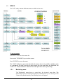
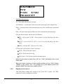
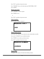
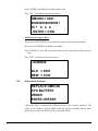

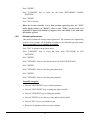

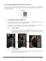


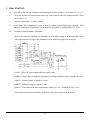


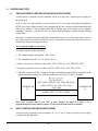
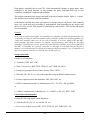

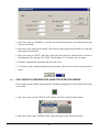
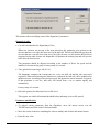
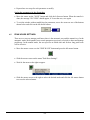
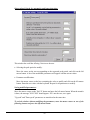

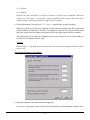
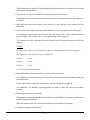
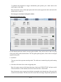
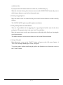
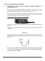
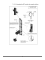
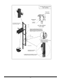
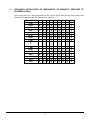

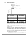

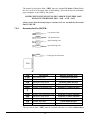
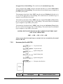
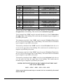
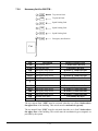
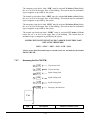

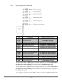
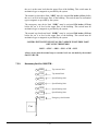
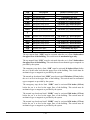
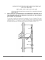
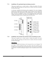

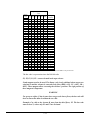
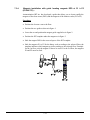
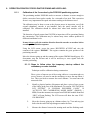
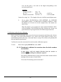

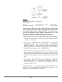
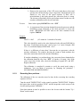
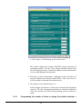

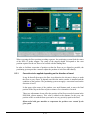

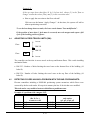
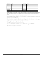
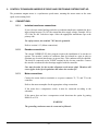


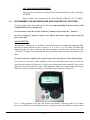
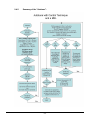
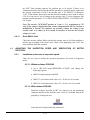
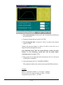


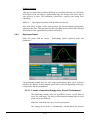
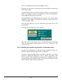

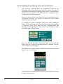
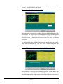

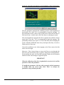
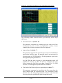


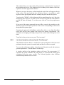
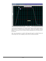

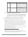


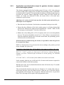
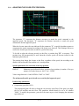
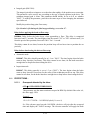
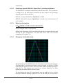
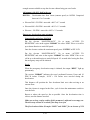

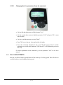
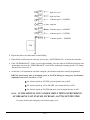
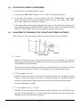
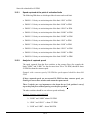
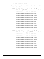


![CASBEE柏[戸建]LR1(PDF形式:1044KB)](http://vs1.manualzilla.com/store/data/006612808_2-5ed36873bbd1c6f331cc4a945d355d8b-150x150.png)