1
USER’S MANUAL
JVF-4000-10 ANG
VARIABLE FREQUENCY
ELEVATOR CONTROLLER
CJ1M PROCESSOR
VARIABLE SPEED DRIVE
CONTROL TECHNIQUES SP OR KEB
JVF-4000 SERIES
CODE B44-07
VERSION JVF-4000_CT/KEB_A_10-4.6
TABLE OF CONTENT
1.
LCD USE (JRT-LCD): ............................................................................................................................................................ 1-1
1.1.
1.2.
2.
KEYBOARD: ................................................................................................................................................................... 1-1
MENUS: .......................................................................................................................................................................... 1-2
1.2.1. Monitoring menu: ............................................................................................................................................ 1-3
1.2.2. Register Access menu: ..................................................................................................................................... 1-4
1.2.3. Active faults list menu: ..................................................................................................................................... 1-6
1.2.4. Construction mode menu: ................................................................................................................................ 1-6
1.2.5. Recording floor position menu: ....................................................................................................................... 1-7
1.2.6. Elevator options menu: .................................................................................................................................... 1-7
1.2.7. Password menu: ............................................................................................................................................... 1-8
USE OF THE PROGRAMMING CONSOLE (PRO01 OU PRO27): ................................................................................. 2-1
2.1.
2.2.
2.3.
PROGRAMMING CONSOLE CONNECTION: ........................................................................................................................ 2-1
2.1.1. On the CJ1M PLC: .......................................................................................................................................... 2-1
2.1.2. On the CPM2C PLC: ....................................................................................................................................... 2-1
VISUALISING AND MODIFYING A DM (ELEVATOR CONFIGURATION): ............................................................................. 2-2
CONSULTING THE ALARMS: ............................................................................................................................................ 2-2
3.
TEMPORARY START-UP: ................................................................................................................................................... 3-1
4.
FINAL START-UP: ................................................................................................................................................................. 4-1
5.
CONTROLLER TYPE: .......................................................................................................................................................... 5-1
5.1.
5.2.
5.3.
5.4.
5.5.
6.
OPERATION PRINCIPLE FOR CAR ZONING AND LEVELLING: ............................................................................. 6-1
6.1.
6.2.
6.3.
6.4.
6.5.
7.
TWO CAR GROOP CONTROLLER (WITHOUT DISPATCHER):............................................................................................... 5-1
GOUP CONTROLLER (WITH DISPATCHER): ...................................................................................................................... 5-1
CLOCK SETTING ON DISPATCHER WITH OPERATOR SCREEN: ........................................................................................... 5-3
CALL DISPATCH CONFIGURATION, USING THE OPERATOR SCREEN:................................................................................. 5-4
PEAK HOURS SETTINGS:.................................................................................................................................................. 5-6
WITH A STANDARD TAPE SELECTOR (ZONING BY MAGNET PULSES): (IP8300 BIN4 W10): ............................................ 6-1
USING A PERFORATED TAPE OR A ENCODER ON THE GOVERNOR: ................................................................................... 6-5
6.2.1. Installation of the perforated tape: .................................................................................................................. 6-5
6.2.2. Installation of the standard tape selector and the governor encoder: ............................................................. 6-6
6.2.3. Installation of the "Door Zone" and bar code magnets at each floor .............................................................. 6-7
6.2.4. Magnets installation with IP1200-TP1 guide: ................................................................................................. 6-9
6.2.5. High speed counter verification:.................................................................................................................... 6-10
6.2.6. Recording of floors position: ......................................................................................................................... 6-11
6.2.7. Programming the number of holes for slowdown: ......................................................................................... 6-12
VERIFICATION OF THE HIGH SPEED COUNTER (COUNT LOSS): ...................................................................................... 6-13
DETECTING FLOORS HAVING A PROBLEM WITH THE BAR CODE MAGNETS: ................................................................... 6-14
HOISTWAY ACCESS TRAVEL ADJUSTMENT: .................................................................................................................. 6-15
6.5.1. With performed tape or encoder installed on the governor : ......................................................................... 6-15
6.5.2. With Standard tape: ....................................................................................................................................... 6-16
CONTROL TECHNIQUES UNIDRIVE SP DRIVE START-UP: ..................................................................................... 7-1
7.1.
7.2.
CONNECTIONS: ............................................................................................................................................................... 7-1
7.1.1. Isolation transformer connections: .................................................................................................................. 7-1
7.1.2. Encoder connections:....................................................................................................................................... 7-1
7.1.3. Motor connections: .......................................................................................................................................... 7-1
FUNCTIONNING OF THE DRIVE: ....................................................................................................................................... 7-2
7.2.1. Drive keyboard operation: ............................................................................................................................... 7-2
7.2.2. Modifying a drive parameter: .......................................................................................................................... 7-3
7.3.
7.4.
7.5.
7.6.
7.2.3. Drive parameter backup: ................................................................................................................................. 7-3
7.2.4. Accessing the error messages list: ................................................................................................................... 7-4
PROGRAMMING OF THE ENCODER AND MOTOR PARAMETERS: ........................................................................................ 7-6
7.3.1. Encoder parameters: ....................................................................................................................................... 7-6
7.3.2. Motor parameters: ........................................................................................................................................... 7-6
PROGRAMMING THE ENCODER PHASE ANGLE AND MOTOR “AUTOTUNE”: ...................................................................... 7-7
7.4.1. "Trip TunE" fault during the "Autotune": ........................................................................................................ 7-8
7.4.2. "Trip TunE1" fault during the "Autotune": ...................................................................................................... 7-8
7.4.3. "Trip TunE2" fault during the "Autotune": ...................................................................................................... 7-8
7.4.4. Rotation test, the elevator goes down when the PCH signal is activated: ....................................................... 7-8
7.4.5. Summary of the "Autotune": ............................................................................................................................ 7-9
7.4.6. Encoder verification: ..................................................................................................................................... 7-10
7.4.7. Marking of the encoder’s position: ................................................................................................................ 7-10
7.4.8. Encoder Replacement: ................................................................................................................................... 7-10
7.4.9. Drive ENC2 fault: .......................................................................................................................................... 7-10
7.4.10. Drive ENC7 fault: .......................................................................................................................................... 7-11
7.4.11. Drive ENC10 fault: ........................................................................................................................................ 7-11
PROGRAMMING THE SPEED DRIVE GAINS:..................................................................................................................... 7-11
7.5.1. Speed drive gain: ........................................................................................................................................... 7-11
7.5.2. Speed drive current gain (Nervous or loud motor): ....................................................................................... 7-12
SPEED, ACCELERATION/DECELERATION PARAMETERS PROGRAMMING: ....................................................................... 7-12
7.6.1. Programming of operations speeds: .............................................................................................................. 7-12
7.6.2. Rounding up factors (S-Curves): ................................................................................................................... 7-13
7.6.3. Accelerations and decelerations: ................................................................................................................... 7-13
7.6.4. Adjustments to obtain comfortable starts and stops: ..................................................................................... 7-14
7.6.5. Pre-load torque command ("PRELOAD TORQUE"): ................................................................................... 7-14
7.6.5.1. No weighing system with a fixed command: .................................................................................................... 7-15
7.6.5.2. Weighing system with linear output signal: ...................................................................................................... 7-15
7.7.
7.8.
8.
7.6.6. Speed deviation problem detection compared to real speed:......................................................................... 7-17
SMARTCARD (0.30): ..................................................................................................................................................... 7-18
7.7.1. Saving the smartcard: .................................................................................................................................... 7-18
7.7.2. Changing the drive parameters from the smartcard:..................................................................................... 7-19
OVER SPEED TEST 125%: ............................................................................................................................................. 7-19
7.8.1. Parameters modification to reach 125% with elevator of more than 200FPM: ............................................ 7-20
KEB VARIABLE SPEED DRIVE START UP: .................................................................................................................... 8-1
8.1.
8.2.
8.3.
8.4.
8.5.
8.6.
CONNECTIONS: ............................................................................................................................................................... 8-1
8.1.1. Isolation transformer connecting: ................................................................................................................... 8-1
8.1.2. Encoder connecting: ........................................................................................................................................ 8-1
8.1.3. Motor connecting:............................................................................................................................................ 8-1
PROGRAMMING DRIVE FUNCTIONING:....................................................................................................................... 8-2
8.2.1. Drive keypad operation: .................................................................................................................................. 8-2
8.2.2. Drive parameter modification: ........................................................................................................................ 8-3
8.2.3. Saving the parameter in the drive: ................................................................................................................... 8-4
8.2.4. Access to the fault message list: ....................................................................................................................... 8-4
ENCODER AND MOTOR PARAMETERS PROGRAMMING: ................................................................................................... 8-5
8.3.1. Encoder parameters: ....................................................................................................................................... 8-6
8.3.2. Motor Parameters:........................................................................................................................................... 8-7
8.3.3. Elevator parameters programming: ................................................................................................................ 8-8
PROGRAMMING OF THE ENCODER PHASE ANGLE AND MOTOR “AUTOTUNE”: ................................................................. 8-8
8.4.1. Rotation test, the elevator goes down when the PCH signal is activated: ..................................................... 8-10
8.4.2. E.EnCC drive fault: ....................................................................................................................................... 8-10
PROGRAMMING OF THE VARIABLE SPEED DRIVE GAINS: ............................................................................................... 8-10
8.5.1. Variable speed drive gain: ............................................................................................................................. 8-10
8.5.2. Drive current gain(Nervous our noisy motor): .............................................................................................. 8-11
SPEED PARAMETERS PROGRAMMING, ACCELERATION/DECELERATION: ....................................................................... 8-11
8.6.1.
8.6.2.
8.6.3.
8.6.4.
8.6.5.
Operations speed programming: ................................................................................................................... 8-11
Roundup factors (S-Curves): ......................................................................................................................... 8-12
Accelerations and decelerations: ................................................................................................................... 8-12
Adjustments to obtain comfortable starts and stops: ..................................................................................... 8-12
Preload torque command ("PRELOAD TORQUE"): .................................................................................... 8-13
8.6.5.1. No weighing system with a fixed command: .................................................................................................... 8-13
8.6.5.2. Weighing system with linear output signal: ...................................................................................................... 8-13
8.7.
9.
8.6.6. Speed deviation problem detection compared to real speed:......................................................................... 8-15
125% GOVERNOR OVERSPEED TEST: ............................................................................................................................ 8-15
8.7.1. Parameters modification to reach 125 % with an elevator of more than 200 FPM: ..................................... 8-16
SLOWDOWN NORMAL LIMITS ADJUSTMENT AND EMERGENCY TERMINAL STOPPING DEVICE
SYSTEM FOR TOP AND BOTTOM FLOORS:.................................................................................................................. 9-1
9.1.
NORMAL AND SLOWDOWN LIMIT SWITCHES INSTALLATION FOR ELEVATORS 200FPM OR LESS: ................. 9-1
9.1.1. Elevator using magnets tape slector: ............................................................................................................... 9-1
9.1.2. Elevator with perforated tape or encoder installed on the governor:.............................................................. 9-2
9.1.3. Schmersal magnetic switch installation supplied by Automatisation JRT Inc. ................................................ 9-3
9.1.4. Normal slowdown limit position correction for perforated tape or governor encoder: .................................. 9-6
9.1.5. “UCM” aditional processor for contract speed elevators 150 FPM or less: .................................................. 9-7
9.1.6. “UCM” processor faults for contract speed elevators 150 FPM or less: ....................................................... 9-7
9.1.7. “NTSD” aditional processor for contract speed elevators 200 FPM: ............................................................ 9-7
9.1.8. “NTSD” processor faults for contract speed elevators 200 FPM: .................................................................. 9-8
9.1.8.1. Fault codes indicator using “NTSD” processor outputs: ..................................................................................... 9-8
9.1.8.2. Using the LCD in the controller to access “NTSD” processor fault codes:......................................................... 9-9
9.2.
9.1.9. “NTSD” processor with independent position feedbacks:............................................................................. 9-11
NORMAL AND SLOWDOWN LIMIT SWITCHES INSTALLATION FOR ELEVATORS WITH CONTRACT SPEED
HIER THAN 200FPM: ................................................................................................................................................ 9-13
9.2.1. Elevator contract speed from 201 fpm to 250 fpm: ........................................................................................ 9-13
9.2.2. Elevator contract speed from 251 FPM to 400 FPM..................................................................................... 9-15
9.2.3. Schmersal magnetic switch installation supplied by Automatisation JRT Inc. .............................................. 9-18
9.2.4. Normal slowdown limit position correction for perforated tape or governor encoder: ................................ 9-23
9.2.5. “NTSD” aditional processor for contract speed elevators greater than 200 FPM:...................................... 9-24
9.2.6. “NTSD” processor faults for contract speed elevators greater than 200 FPM: ........................................... 9-24
9.2.6.1. Fault codes indicator using “NTSD” processor outputs: ................................................................................... 9-24
9.2.6.2. Using the LCD in the controller to access “NTSD” processor fault codes:....................................................... 9-25
9.2.7.
9.2.8.
“ETSD” aditional processor for contract speed elevators greater than 200 FPM: ...................................... 9-27
“ETSD” processor faults for contract speed elevators greater than 200 FPM: ........................................... 9-27
9.2.8.1. Fault codes indicator using “ETSD” processor outputs: ................................................................................... 9-27
9.2.8.2. Using the LCD in the controller to access “ETSD” processor fault codes: ....................................................... 9-28
9.2.9. “NTSD” processor independent position feedbacks: .................................................................................... 9-30
9.2.10. “ETSD” Emergency terminal stopping devices parameters: ........................................................................ 9-32
9.2.11. ETSD Emergency terminal stopping device test procedure:.......................................................................... 9-34
10. UNCONTROLLED SPEED DETECTION CIRCUIT ADJUSTMENT FOR 200 FPM ELEVATORS: ...................... 10-1
11. EMERGENCY BRAKE, GTS RELAY CIRCUIT AND BUFFER TEST: ...................................................................... 11-1
11.1. ASCENDING CAR OVERSPEED PROTECTION .................................................................................................................. 11-2
11.2. 125% TEST FOR EACH BRAKE PAD................................................................................................................................ 11-3
11.2.1. If normal and emergency brakes drops at every car stops (drum brake)....................................................... 11-3
11.2.2. If emergency brakes drops in emergency case only (disk brake). .................................................................. 11-4
11.3. UNINTENDED CAR MOVEMENT PROTECTION ................................................................................................................ 11-5
11.3.1. Down direction, with 125% of the rated load ................................................................................................ 11-5
11.3.2. Up direction with no load .............................................................................................................................. 11-6
11.4. BUFFER TEST WITH PERFORATED TAPE OF ENCODER: ................................................................................................... 11-7
11.4.1. To perform a buffer test at the top floor: ....................................................................................................... 11-7
11.4.2. To perform a buffer test at the bottom floor: ................................................................................................. 11-7
11.4.3. Restarting the elevator:.................................................................................................................................. 11-8
12. INTERNAL FUNCTIONS AND CONTROLLER CONFIGURATION: ........................................................................ 12-9
12.1. MODIFYING THE DM WITH THE LCD: .......................................................................................................................... 12-9
12.2. MODIFYING THE DM WITH THE PROGRAMMING TOOL: ................................................................................................ 12-9
12.3. MODIFYING THE DM OR THE OPERATING TIME WITH THE OPERATOR SCREEN FOR THE GENERAL FUNCTIONING
SECTION: .....................................................................................................................................................................12-10
12.3.1. Time changing of certain timer with the screen operator: ........................................................................... 12-11
12.4. CONTROL OF DOORS: ...................................................................................................................................................12-14
12.5. VARIABLE SPEED DRIVE: .............................................................................................................................................12-15
12.6. BRAKE: .......................................................................................................................................................................12-15
12.7. FLOOR CALLS: .............................................................................................................................................................12-15
12.8. GONG: .........................................................................................................................................................................12-15
12.9. POSITION INDICATOR + SU/SD DIRECTION: ................................................................................................................12-16
12.10. EMERGENCY RECALL: .................................................................................................................................................12-16
12.11. EMERGENCY POWER OPERATION: ................................................................................................................................12-17
12.12. PRIORITY SERVICE (BLUE CODE AND FREE CAR): ........................................................................................................12-17
12.13. POSITIONNING/SPEED/BOTTOM SWITCHES: ..................................................................................................................12-17
12.14. VARIOUS: ....................................................................................................................................................................12-18
12.15. RETURN TO SIMPLEX AND DUPLEX CONTROLLER PARKING: ........................................................................................12-18
12.16. HOME PARKING FOR TWO-CAR GROUP CONTROLLERS DUPLEX:...................................................................................12-18
12.17. HOME PARKING FOR GROUP CONTROLLER WITH OPERATOR SCREEN: ..........................................................................12-20
12.17.1. Opened doors parking for groups with dispatcher: ..................................................................................... 12-22
12.17.2. Opened doors parking for simplex elevators: .............................................................................................. 12-23
12.17.3. Parking floors: ............................................................................................................................................. 12-23
12.18. UP PEAK PERIOD (OPTIONAL) FOR GROUP CONTROLLER (WITH SEPARATE DISPATCH): ................................................12-26
12.19. DOWN PEAK PERIOD (OPTIONAL) FOR GROUP CONTROLLER (WITH SEPARATE DISPATCH): ..........................................12-26
12.20. NEXT CAR UP (FOR GROUP CONTROLLER WITH SEPARATE DISPATCH ONLY):...............................................................12-26
12.21. UP PEAK PERIOD FOR A TWO-CAR GROUP CONTROLLER (WITHOUT SEPARATE DISPATCH): ..........................................12-26
12.22. DOWN PEAK PERIOD FOR TWO-CAR GROUP (WITHOUT SEPARATE DISPATCH): .............................................................12-27
13. SYMBOLS LISTING: ........................................................................................................................................................... 13-1
14. MAINTENANCE: .................................................................................................................................................................. 14-1
14.1. ALARMS AND FAULTS: ................................................................................................................................................. 14-1
14.1.1. Alarms and status list: ................................................................................................................................... 14-1
14.1.2. Visualization of the alarms in the CJ1M PLC controller: ............................................................................. 14-1
14.1.3. Automatic erasing of the alarms: ................................................................................................................... 14-2
14.1.4. Look up the drive alarms and faults: ............................................................................................................. 14-2
14.1.5. « UCM », « NTSD » and « ETSD » processors fault list access:................................................................... 14-2
14.1.5.1.
14.1.5.2.
14.1.5.3.
14.1.5.4.
« UCM » processor faults for contract speed elevators 150FPM or less : ......................................................... 14-3
« NTSD » processor faults for contract speed elevators 200 FPM : .................................................................. 14-4
« NTSD » processor faults for contract speed elevators greater than 200 FPM : .............................................. 14-6
« ETSD » processor faults for contract speed elevators greater than 200 FPM : .............................................. 14-7
14.2. PLC BATTERY REPLACEMENT: ....................................................................................................................................14-10
14.3. INPUT/OUTPUT MODULES: ...........................................................................................................................................14-11
14.3.1. Reading inputs and outputs on modules of more than 16 inputs or outputs: ............................................... 14-12
14.4. PEAK VOLTAGE PROTECTION:......................................................................................................................................14-15
14.5. ALARMS DESCRIPTION: ...............................................................................................................................................14-16
15. DRIVE CONTROL TECHNIQUES SP (MENU PARAMETERS 0): .............................................................................. 15-1
16. KEB DRIVE (ELEVATOR FUNCTION): .......................................................................................................................... 16-1
APPENDIX A: SEQUENCE DESCRIPTION.............................................................................................................................. A-1
APPENDIX B: ILC3 WEIGHING DEVICE ................................................................................................................................ B-1
APPENDIX C: LCD MONITOR INSTRUCTIONS.................................................................................................................... C-1
APPENDIX G : BRAKE RELEASE UNIT : ...............................................................................................................................G-1
NOTES AND PRECAUTIONS
• The controller must be installed by competent people who possess the suitable training and cards for
the installation of elevator controllers;
• The controller’s power supply must come from a fuse switch supplied by others. The fuses value must
respect the electrical code;
• It is necessary to install a separate conductive element to ground the controller in the mechanical
room. To know the size of the conductive element, check the electrical code. An indirect grounding
(e.g. water pipes) may cause intermittent troubles and electrical noises may occur;
• Please note the controller comes with a one (1) year guarantee, effective on the day of billing. An
improper use of the controller, an incorrect connection or the disregard of the user’s manual may void
the guarantee. Also note that only the components are guaranteed;
• In case of an incorrect connection, the controller is protected by TVS which can short-circuit. Verify
the functioning and replace them if needed.
• Allow enough space between the resistor bank, located on top of the controller, and the machine room
ceiling for the dynamic braking resistor may be from 4,000 to 30,000 watts (see drawings).
Operating conditions:
• The 3 phases entry voltage may vary of more or less 10 %;
• A 60HZ frequency is standard, a 50HZ frequency is available on special order;
• The operating temperature is 0 to 45°C;
• The relative humidity is 95 %;
• Do not install the NEMA 1 standard enclosure in a dusty environment or where there is risk of water
infiltration. Other types of enclosures are available upon request (NEMA 4, 12 etc.);
• Please contact Automatisation JRT Inc. if the motor is installed at 50 ft. or more from the controller;
• CSA approval.
General information:
JVF-4000 series controllers were developed for a quick and easy installation and operation with a
permanent magnets motor. The controllers have functions of internal self-diagnosis, which allow an easy
maintenance. There are also several functions that are programmable by the user.
Thus, it is very important to read thoroughly the manual, for a quick and secure installation. Please
note that this controller cannot operate without an encoder.
There are two ways to program the controller options. The first option is the LCD screen installed inside
the controller. It allows configuring the elevator but you cannot modify the plc’s program if a sequence
modification is required. The second option is the programming console (CQM1-PRO01-E or C200HPRO27). This option allows programming of the plc if a sequence modification is required. The second
option is not necessary for the elevator start-up.
General features:
• Number of floors: 64
• Maximum number of cars: 12
1. LCD USE (JRT-LCD):
This section is a summary of the supervision utility. Refer to appendix C for a complete description.
The LCD lets you visualize the state of the elevator controller (floor, speed in FPM, perforated tape
position, alarms, etc.), modify the plc’s configuration registers and also to record car calls and hall calls
from a distance. The utility offers the possibility to have the information displayed in French or English.
The utility is provided with different light-emitting diodes "LED". The "POWER" LED indicates that the
utility is power supplied. The "LED2" blinks to indicate that the program is functioning normally.
Though, if the "LED2" stays on or off at all times, the program is not in an operational, you must reset
the power.
When the elevator is in trouble, the screen of the "LCD" utility will blink to warn the user.
1.1.
KEYBOARD:
The "UP/DOWN" keys allow access to the main menus or sub-menus. They also allow changing
the value of a parameter.
The "LEFT/RIGHT" keys allow placing the cursor on the parameter to modify.
The "ENTER" key allows access to a sub-menu. It also allows saving of a new value.
The "ESC" allows to return to the main menus or to cancel a parameter modification.
1-1
1.2.
MENUS:
The "LCD" utility contains differents menus available to the users.
To access a menu:
• Press "ESC" to access to the menus list.
• Press on the "UP/DOWN" keys to select a menu.
• Press "ENTER" to access the menu.
The "LCD" utility has a protection that locks the menus where it is possible to modify a value
or a parameter. In order to access to these menus, the user must enter the password. See
section "1.2.7 Password Menu" (The LCD is locked after three hours of inactivity).
1-2
1.2.1.
Monitoring menu:
The "Monitoring" menu shows, in actual time, the elevator’s status data. This
information may be used during the temporary and final start-up. At a start-up or after
2 hours of keyboard inactivity, the following screen will appear:
IN AUTOMATIC
PI=12
P=1234
S=1234
PS0 ACC0 STP
Presented informations:
• PI. = Floor where the elevator is located.
• AUTOMATIC = Actual status of the elevator (See next page for the complete list).
• POSI. = Actual position of the perforated tape (only if the controller has a
perforated tape).
• SPD. = Elevator actual speed in FPM (only if the controller has perforated tape).
• If the elevator is traction, the last line is for the drive.
PSX = Preset speed X. PS0 = Preset speed 0 (see the drawings at the drive
page).
ACCX = Accel or decel X. ACC1 = Accel 1 (see the drawings at the drive
page).
FOW = Forward, REV = Reverse, STP = Stop.
• If "Soft-Start", the last line is for the "Soft-Start":
STOP = The elevator don’t moves.
RUN = The elevator is moving.
Up to speed = The elevator reach the maximum speed.
If there is more than one status in the PLC, the "LCD" will display at the second
all the status.
When the elevator controller is in floor position upload cycle, the "LCD" displays
"DM483" at the position "PI.=". It is possible to see if the number of door zone
magnets (DZO) is the same as the number of floors.
1-3
1.2.2.
Register Access menu:
This menu allows reading and writing in one of the PLC’s register. The "DM"
registers are used to configure the elevator.
• Press "ESC" to go back to the previous menu.
• Press "UP/DOWN" keys to select the main menu "REGISTERS ACCES".
• Press "ENTER".
Register type selection:
• Press "UP/DOWN" to select a register.
• Press "ENTER" to save.
or
• Press "ESC" to go back to the previous menu.
Choice of registers:
• DM, CH, HR and AR (for CJ1M PLC).
REGISTER TYPE ?
->DM
Register number selection:
• Press on the "LEFT/RIGHT" keys to place the cursor on the number to modify.
• Press on the "UP/DOWN" keys to modify the number.
• Press "ENTER" to save and to go to the next menu.
• Press "ESC" to go back to the previous menu.
1-4
REGISTER NUMBER
->DM0000
Register Value:
The register value is shown in hexadecimal and binary formats.
• Press "ENTER" to modify the selected register value.
• Press "ESC" to go back to the previous menu.
DM0000 = 0001
0000000000000001
15 ^ 8 4 0
ENTER = CHG
Modifying the register value:
• Press on the "LEFT/RIGHT" keys to place the cursor on the number to modify.
• Press on the "UP/DOWN" to modify the number.
• Press "ENTER" to save and to go back to the previous menu and visualize de new
value.
• Press "ESC" to return to the previous menu.
->DM0000
OLD = 0001
NEW = 1234
1-5
1.2.3.
Active faults list menu:
REPLACE OMRON
CPU BATTERY
HR8001
ENTER->ERASE
This menu allows visualising the different alarms in the elevator controller. The
utility "LCD" displays "NO ALARM" when the elevator controller has no more
alarms. Press on the "UP/DOWN" keys to scroll the alarms.
Visualizing the alarms:
• Press "ESC" to return to the previous menu.
• Press "UP/DOWN" keys to select the main menu "ALARMS & CPU I/O
CHECKING".
• Press "ENTER".
• Press "UP/DOWN" keys to select the sub menu "ACTIVE FAULTS LIST".
• Press "ENTER".
To erase the alarms:
•
1.2.4.
Press the "ENTER" keys, the LCD will shows an other windows to make a
confirmation.
Construction mode menu:
The Construction mode disables temporarily certain detections to facilitate the
elevator car construction in Inspection mode. As soon as the elevator controller is
placed in Automatic mode and that a call has been placed, the Construction mode will
be deactivated automatically and all signals will be in function.
The elevator controller must be in Inspection mode.
• Press "ESC" to return to the previous menu.
• Press "UP/DOWN" keys to select the main menu "OPERATION MODE".
• Press "ENTER".
• Press "UP/DOWN" keys to select the sub menu "CONSTRUCTION MODE".
1-6
• Press "ENTER".
• Press "UP" to activate the Construction mode.
1.2.5.
Recording floor position menu:
This menu allows launching a function that registers floors when the controller uses a
perforated tape or an encoder on the governor for the floor positioning. Refer to
section 6.2.6.
The elevator controller must be in Inspection mode.
• Press "ESC" to return to the previous menu.
• Press "UP/DOWN" keys to select the main menu "ELEVATOR & LCD
SETTINGS".
• Press "ENTER".
• Press "UP/DOWN" keys to select the sub menu "RECORDING FLOORS
POSITION".
• Press "ENTER".
• Press "UP" to activate.
When the elevator controller is in a floor position registering cycle, the "LCD"
utility displays what is in "DM483" where is says "IND=" on the screen. It is
impossible to know if the number of magnets, door zone (DZO), is the same than
the number of floors.
1.2.6.
Elevator options menu:
This section contains all elevator control parameters. The parameters are separated by
sections. Some sections will be hidden according to the controller type and option.
Refer to appendix C for a complete description.
• Press "ESC" to return to the previous menu.
• Press "UP/DOWN" keys to select the main menu "ELEVATOR & LCD
SETTINGS".
• Press "ENTER".
• Press "UP/DOWN" keys to select the sub menu "ELEVATOR OPTIONS";
• Press "ENTER".
• Press "UP/DOWN" keys to select the good option menu.
1-7
• Press "ENTER".
• Press "UP/DOWN" keys to select the good parameter.
To modify an option:
1.2.7.
•
Press on "LEFT/RIGHT" keys to edit the parameter.
•
Press on "LEFT/RIGHT" keys to change the digit to modify.
•
Press on "UP/DOWN" keys to change the number.
•
Press on "ENTER" to save the new value and exit edition mode.
•
Press on "ESC" key to exit without saving.
•
Repeat for all parameters that you want to change.
Password menu:
This menu allows entering a password to unlock the parameters modification menus.
The password is "1234". After 2 hours of keyboard inactivity, the "LCD" utility will
be locked again.
PASSWORD :
1234
• Press "ESC" to return to the previous menu.
• Press "UP/DOWN" keys to select the main menu "PASSWORD".
• Press "ENTER".
Entering the password:
• Press on the "LEFT/RIGHT" keys to place the cursor on the number to modify.
• Press on the "UP/DOWN" keys to modify the number.
• Press "ENTER" to save.
or
• Press "ESC" to return to the previous menu.
1-8
2. USE OF THE PROGRAMMING CONSOLE (PRO01 OU PRO27):
The programming console, as the LCD utility, allows access to the visualisation and modification
registers. It is also possible, under the supervision of Automatisation JRT Inc., to modify or add a
programming sequence.
2.1.
PROGRAMMING CONSOLE CONNECTION:
The programming console is connected on the peripheral port "PERIPHERAL" of the PLC.
Always leave the key on the console in "MONITOR" mode.
For example if the peripheral port is already used by the LDC supervision, do not forget to
reconnect it once it’s done. The switches must also be put back as they were.
2.1.1.
On the CJ1M PLC:
Open the "SW SETTING AND BATTERY" door located on top of the
communication port and put the switch "4" at "OFF". The console will only display
hyphens if the switch"4" is not "OFF" (RIGHT).
2.1.2.
On the CPM2C PLC:
Open the door on top of the "CN1" connector to access the communication port. Put
the switches "SW1" and "SW2" at "OFF".
2-1
2.2.
VISUALISING AND MODIFYING A DM (ELEVATOR CONFIGURATION):
For example, to access register 492, you must do as followed:
• CLR
MONTR
• DM
492
3
MONTR
Screen =
DM492
0000
DM492
1234
To modify a register, do as followed:
• CHG
1234
WRITE
Screen =
To return to the beginning:
• CLR
2.3.
CLR
CONSULTING THE ALARMS:
• CLR
MONTR
• SHIFT
CH/*DM
3
HR
80
MONTR
SHIFT
MONTR
HR80
0000000001000000
Bit15
Bit0
Screen =
• Thus, only the HR8006 alarm is activated. Do
to visualise le HR81:
HR81
0000010010000000
Bit15
Bit0
Screen =
• Thus, HR8107 are HR8110 are activated.
• Do
to see the other registers.
REFER TO SECTION 14.5 FOR THE ALARMS DESCRIPTION.
2-2
3. TEMPORARY START-UP:
With this controller type, the drive “Autotune” should be execute without ropes or with a balanced
car.
A.
Install jumpers between the following terminals:
• "J0" and "J1" (governor);
• "J1A" and "J1" (emergency brake circuit);
• "J1" and "J6" (hoistway access line);
• "J6" and "J9" if there is no car top inspection box;
• "J9" and "J10" (car stop) and special emergency stop, PH2;
• "J10" and "LNH" (normal up limit);
• "J10" and "LNB" (normal down limit);
• "J9" and "PP" (hall doors closed);
• "J9" and "PC" (car door closed);
• "J9" and "HDL" (hall doors locked if manual doors or motorised cam);
• "PCH" and "LTT" (extreme high limit in inspection).
• « ISR » and « ISR1 » (in car inspection key switch).
208-460-600 volts controller without isolation transformer:
Connect the main power supply with the main switch has indicated in the drawings.
For the first time, remove the 3 fuses and measure the voltage.
208-460-600 volts controller with isolation transformer:
Supply the drive power section with the isolation transformer using the appropriate primary and
secondary connections as specified in the drawings at chapter 7, section 7.1.1 for the Control
Techniques drive and at chapter 8, section 8.1 for the KEB drive. Another line must power the
controller.
Put "XO" terminal to ground.
For the first time, remove the 3 fuses and measure the voltage.
3-1
B.
Connect the motor, the encoder and the temperature sensor as specified at chapter 7, section 7.1
for the Control Techniques drive and at chapter 8, section 8.1 for the KEB drive.
Provide a copper conductor for the electrical grounding of the motor.
C.
The variable speed drive has its own internal electronic overload protection. It will adjust itself
with the motor current parameters.
D.
Measure:
• Controller power voltage (see drawings)
• 120 volts AC between "J" and "N", "JC" and "N".
• 24 VDC between "+A" and "COM", "+AC" and "COM", "+GR" and "COM", ("+DC" and
"COM") (internal voltage), "+24V" and "COM" (tape selector or governor encoder voltage).
E.
The PLC "POWER" and "RUN" green lights must be on at all time.
F.
To move in inspection mode :
Controller inspection :
Put the hall and car doors derivation switches at the position "OFF".
Put a jumper between the terminals "+A" and "ISR". Put the inspection switch at the position
“INSPECTION”. Press on the buttons “UP” or “DOWN” of the “JRT-INT-02” card to move the
elevator.
Top of the car inspection or remote control :
Do not connect the terminal "ISR". The signal corresponding to “ISR” must be turned off.
Connect the button “UP” and “DOWN” with your remote between the terminals “+A” and
“PCH” and “+A” and “PCB”.
G.
CONSTRUCTION MODE
The "construction" mode deactivates temporarily certain detections to facilitate the elevator car
construction in "inspection" mode. As soon as the elevator controller is placed in "automatic"
mode and that a call has been placed, the "construction" mode will be deactivated automatically
and all signals will be in function.
The elevator controller must be in "inspection" mode
With the controller’s LCD screen:
• Press "ESC" to return to the previous menu.
• Press "UP/DOWN" keys to select the main menu "OPERATION MODE".
3-2
• Press "ENTER".
• Press "UP/DOWN" keys to select the sub menu "CONSTRUCTION MODE".
• Press "ENTER".
With the programming console (CQM1-PRO01):
Put the value 0001 in DM 249 to activate the mode (see section 2).
Deactivated Circuits:
• Brake contact supervision.
• Motor temperature "THM".
• Generator signals "GEN1, GEN2".
• Switches supervision "LRH, LRH1, LRB and LRB1".
• Switches supervision "SLH and SLB".
• Motor overload alarm de surcharge for speed reduction (Only the drive protects the motor).
• Bar code inputs "P1, P2, and P3... "
• The fire signals are completely deactivated.
• Car overload signal "LW2".
• All the outputs that set off the alarms are deactivated.
H.
At this point of the procedure, please verify:
PLC inputs which must be activated:
• +A, +DC, PC, PP, GTS, LNH, LNB, J, SW6, RDY, SR.
• HDL (locked hall door contact if manual door or motorised cam).
The relays:
• ISR must not be activated.
• R5 must be activated.
• ETSL must be activated for the elevators going faster than 200 FPM.
• BRK must be activated.
3-3
The alarms:
• Hold the « MANUAL RESET » button, located on the controller inspection board, for 2.5
seconds. This action reset the controller if every conditions are good and clear the alarms.
• By using the LCD, erase the alarms and then consult the alarms list to check that there are no
more. (Section 1 for use of the LCD).
I.
Execute the start-up procedures of the drive described at chapter 7 up to section 7.4 included for
the Control Techniques drive or at chapter 8, up to section 8.3.3 included for the KEB drive.
J.
Adjust the brake:
• At Start-up: The holding voltage (if applicable) must be adjusted as the controller drawing on
page 2. The length of the overexcitement voltage is adjustable by using a potentiometer or by
(DM44) register in the PLC. That delay should be around 1 second.
• At Stopping: The brake must be applied completely after 0,2 second. If the car is moving free
wheel when the brake drops see section 7.6.4 for Control Techniques drive or section 8.6.4 for
KEB drive.
Note: It is important to provide 4 wires for the brake coils connection, which will allow 125 %
load tests with normal brake and emergency brake separately.
• Connect the brake’s auxiliary contacts to the controller’s "BRC" terminal as per the electrical
drawing. (See section 12.6 to activate or deactivate the breaking switch supervision and to set
the contact (NO/NC)).
IMPORTANT
The PLC inputs are designed to operate 24 volts DC. DANGER: Never apply 120 volts AC for
it may cause severe damage to the inputs.
On reception of the controller, the "COM" terminal is grounded.
K.
The car may now be moved in inspection by using a jumper between "+A" and "PCH" to go up
or between "+A" and "PCB" to go down. The car may also be moved using the controller’s "UP"
and "DOWN" buttons by putting the controller’s inspection switch in Inspection mode. However,
a jumper must be installed between "+A" and "ISR", the doors’ bypass switches must be at
"OFF" position and the hoistway key deactivated.
L.
Elevator controllers with a contract speed higher than 150 FPM have an uncontrolled speed
detection device. This safety device uses an independent feedback than the normal position
feedback. It can be the perforated tape, the encoder installed on the governor or 2 proximity
sensors installed on the top of the tape reader head. For a maximum safety, it is strongly
recommended to install this feedback early during the start-up. For 200 FPM elevators, this
detection is made by the “NTSD” processor and for elevators with a contract speed higher than
200 FPM “ETSD” processor will detect the uncontrolled speed. See section 9.
3-4
4. FINAL START-UP:
A.
Proceed to the adjustment of the tape selector or the encoder’s governor (Standard tape selector:
section 6.1, perforated tape: section 6.2 or governor’s encoder: section 6.3).
B.
To comply section 2.26.9.4 of the elevator code, “RRC” relay will energize momentary at each
start of the elevator. This relay allows to test critical relays: (ISR, XIN, PC, PP, etc..).
C.
Put the elevator in "maintenance" mode using the controller’s switch. Put the inspection switch to
"NORMAL". It is now possible to place car calls without the doors opening.
D.
Make an optimal calibration of the drive and make the final adjustments of the speeds and
decelerations (see sections 7.5, 7.6 and 7.8 for Control Techniques drive or sections 8.5 and 8.6
for KEB drive).
E.
For elevators 200 FPM or less, proceed to the installation and the mechanical adjustment of the
slowdown limits (see section 9.1).
F.
For elevators 250 FPM and above, proceed to the installation and the mechanical adjustment of
the emergency terminal stopping limits (see section 9.2).
G.
Remove the jumpers of the mechanical slowdown limits terminals (LRH, LRB, LRH1, LRB1).
Remove the jumpers of emergency terminal stopping limits terminals ( SLH, SLB).
H.
Proceeds to the emergency stopping devices adjustments for elevators 200 FPM and above. (see
section 9.2).
I.
Adjust the hoistway access travelling limits (see section 6.4)
J.
Proceed to all tests and adjustments described in sections 11 and 0.
K.
If the controller has a batteries unit to lift the brake in emergency case, read the appendix G to
setup and test the batteries unit.
To erase des alarms (3 ways):
Hold the « MANUAL RESET » button, located on the controller inspection board, for 2.5
seconds. This action reset the controller if every conditions are good and clear the alarms.
Activate the "MAINTENANCE" switch 4 times in a row.
By using the LCD, erase the alarms and then consult the alarms list to check that there are
no more. (Section 1 for use of the LCD).
WARNING
PLC inputs are designed to operate at 24VDC. DANGER: Never apply 120VAC for it may cause
severe damage to the inputs.
On reception of the controller, the COM terminal is grounded.
4-1
5. CONTROLLER TYPE:
5.1.
TWO CAR GROOP CONTROLLER (WITHOUT DISPATCHER):
A main switch is required for each controller. There is no need for a separate power supply for
the group itself.
There is a PLC in each controller; as soon as the two PLC’s are connected together through their
RS232 port or the CanBus network, they automatically become a group and start dispatching hall
calls to one another. If the communication link is broken, they start working as two separate
controllers. Therefore, you do not have to connect both controllers together during building
construction.
That type of controller provides continuous dispatch back up service. This means that as soon as
one of the controllers is turned off, looses power, or becomes in trouble, the other one takes over
all hall calls without clearing any of them.
Two car group (duplex) connection:
You must connect to both controllers:
• The common supply to the group: +GR, COM;
• The entire hall calls: BU, 2U, 3U, etc.2D, 3D, etc.;
• Phase 1 fire services, if there are any: RFP, TSTP, TSTD, FS, ALT, FMR, FH, INCG;
• Emergency generator services if there is:GEN1, GEN2, LAU, UG1, UG2, A1M;
• After that, connect both PLCs together with the communication port RS232 by using the cable
supplied with the controllers or with the CanBus network (CH1,CL1,RET1 et SHD)
CONTROLLER
#1
BU, 2U, 3U, ETC.
2D, 3D, 4D, ETC.
RFP, TSTP, TSTD, FS, ALT, FMR, FH, INCG
GEN1, GEN2, LAU, UG1, UG2, A1M
+GR, COM
COMMUNICATION RS232 or
CanBus (CH1,CL1,RET1 et SHD)
CONTROLLER
#2
Since each controller has its own CPU, if some changes are made to a timer or to a
programmed function described at chapter 12, they must be made in both controllers.
5.2.
GOUP CONTROLLER (WITH DISPATCHER):
A main switch is required for each controller: #1, #2, #3, etc. A separate 120VAC power supply
is required for the dispatcher.
5-1
Each simplex controller has its own CPU, which automatically changes to group mode, when
connected to the group network. At that moment, the group dispatches hall calls to each
controllers according to a sophisticated algorithm.
The program contained in the group is designed to operate in simplex, duplex, triplex (…) modes.
The transition between these modes is automatic.
Each simplex controller has a back up sequence in case the group is not present. Each controller
takes over certain hall calls (according to predetermined areas depending on the project) and
takes over every car call. That sequence is controlled by each elevator’s CPU and the OK signals
of each controller.
Example:
In the case of a nine-storied triplex, the controller #1 could take over hall calls for the floors 1 to
3; controller #2 those for the floors number 4 to 6, controller #3 those for the floors number 7 to
9 and each controller takes over all car calls. Controller #1 receives signals OK2 and OK3,
which confirms that both elevators are present, and functioning, same thing for the other
controllers. Controller #2 receives signals OK1 and OK3 and controller #3 receives signal OK1
and OK2. If controller #2 is absent, controller #1 will take over the hall calls for the floors
number 1 to 6 and controller #3 will take over those for the floors number 7 to 9. If controllers #2
and #3 are absents, controller #1 will take over all hall calls, etc.
Group connection:
Connect to all controllers:
• Terminals "COM" and "+GR";
• Phase 1 fire services: RFP, TSTP, TSTD, FS, ALT, FMR, FH, INCG;
• Emergency generator services if there are any: GEN1, GEN2;
• Hall calls: BU, 2D, 2U, etc. only if the controllers using the RS485 communication;
• Presence signals between the controllers: OK1, OK2, OK3, etc.;
• RS485 communication cables (2 shielded pairs): TX+, TX-, RX+, RX, and SHD.
or
• CanBus Communication (1 shielded pair + 1 x 18AWG) : CH1, CL1, RET1, SHD
Connection to the dispatcher:
Connect the following signals on the dispatcher:
• All hall calls: BU, 2U, 3U, etc. and 2D, 3D, etc.;
5-2
• Fire services if there are any: RFP, TSTP, TSTD, FS, ALT, FMR, INCG, FH;
• Emergency generator services if there are any: GEN1, GEN2, UG1, UG2, UG3, etc;
• RS485 communication cables (2 shielded pairs): TX+, TX-, RX+, RX, and SHD.
TX+
TX+
TX+
TX+
TX+
TX-
TX-
TX-
TX-
TX-
RX+
RX+
RX+
RX+
RX+
RX-
RX-
RX-
RX-
RX-
ELV. #2
ELV. #3
ELV. #4
DISPATCHER ELV. #1
or
• CanBus Communication (1 shielded pair + 1 x 18AWG) : CH1, CL1, RET1, SHD
SHD
SHD
SHD
SHD
CL1
CL1
CL1
CL1
CL1
CH1
CH1
CH1
CH1
CH1
RET1
RET1
RET1
RET1
RET1
GROUP
ELE. #1
ELE. #2
ELE. #3
ELE. #4
Since all controllers have their own CPU, if there is a modification of the timers, or if there is a
programming of the functions described in chapter 12, it must be done on all controllers. If the
system has an operator screen, it is possible to carry out, from that screen, the timer modifications
and the programming of the specified functions simultaneously on all controllers (Please refer to
the operator screen manual).
5.3.
CLOCK SETTING ON DISPATCHER WITH OPERATOR SCREEN:
The dispatcher has a real-time clock; however, it does not add or subtract an hour automatically
when spring or fall comes. It is primarily used for the rush hour variations grid. Thus, it is
important to make sure the clock is set at the right time.
To modify time
• Move the mouse cursor on the clock menu and click on the left mouse button.
5-3
• Move the cursor on "MODIFY", and click on the left mouse button. From then on, the data
boxes are accessible.
• Move the cursor on the box to modify. Enter the new data. Repeat this procedure for each data
that needs to be modified.
• Move the cursor on "SAVE" and click on the left mouse button to send the newly set time to
the dispatcher. The message "SUCCESS" should appear, if it is not the case, save again.
• Windows automatically determines the day of the week.
• To exit the window without modifying the parameters, click on one of the two buttons shown
below.
or
5.4.
CALL DISPATCH CONFIGURATION, USING THE OPERATOR SCREEN:
If the elevator group includes an autonomous dispatcher managing hall calls dispatch, this menu
is accessible:
• Move the cursor over the "SINE WAVE" button, and click on the left mouse button.
• Move the cursor on the "DISPATCHER" option and click on the left mouse button.
5-4
This window allows modifying some of the dispatcher’s parameters.
Dispatch of calls:
• Car calls consideration for dispatching (0-10s):
When two elevators are moving in the same direction, this parameter gives priority to the
elevator that has a car call at the same level of the hall call. The hall call should be given to the
elevator that has a car call at the same level, but if the elevator is to far from the hall call level
compared to the other elevator, the dispatcher will optimise the waiting time and will give the
hall call to the best elevator.
This parameter should be adjusted according to the number of floors, the speed and the
number of elevators in the group. Factory setup at 5 seconds.
• Time gain before removing a call (0-15s):
The dispatcher computes the waiting time for every new hall call and the ones previously
registered. When an interesting time reduction is computed, the hall call will be transferred to
another elevator. According to the elevators speed, this parameter can be increased if required.
If that parameter is too low, hall calls will switch from a car to another rapidly and
continuously.
Factory setup at 5 seconds.
• Hall calls quantity for detection of low traffic level:
This register sets a hall call minimal threshold before indicating a low traffic period.
Parameter modification:
• To upload current parameters from the dispatcher, move the mouse cursor over the
"READ"button and click on the left mouse button.
• Move the cursor on the box containing the value to modify and click the left mouse button.
• Enter the new value.
5-5
• Repeat these two steps for each parameter to modify.
Saving the parameters in the dispatcher:
• Move the cursor on the "SAVE" button and click the left mouse button. When the transfer is
done, the message "SUCCESS" should appear, if it’s not the case, save again.
• To exit the window without modifying the parameters, move the cursor on one of the buttons
shown below and click on the left mouse button:
or
5.5.
PEAK HOURS SETTINGS:
There are two ways to manage peak hours; there is the automatic way and the manual way. In the
automatic mode, the dispatcher uses certain parameters previously received to detect and manage
peak hours. In the manual mode, the user specifies at which time and for how long peak hours
will be effective.
• Move the mouse cursor over the "SINE WAVE" button and press the left mouse button.
• Slide the mouse cursor on the menu "Peak Hour Settings".
• Wait for the menu on the right to appear.
• Slide the mouse cursor to the right to select the desired mode and click the left mouse button
to access the selected menu.
5-6
Observation Criteria for automatic peak hours detection:
This window has a toll bar offering 2 choices to the user.
• Selecting the peak period to modify:
Move the cursor on the text corresponding to the requested peak period, and click on the left
mouse button. A list of the modifiable parameters will appear with the current values.
• Parameter modifications:
Move the mouse cursor on the box containing the value to modify and click on the left mouse
button. Enter the new value with the keyboard. Repeat for all parameters to modify.
Saving modified parameters:
Move the mouse cursor on the "SAVE" button and press the left mouse button. When the transfer
is done, the message "SUCCESS" should appear. If it’s not the case, save again.
"Up peak" and "Down peak" parameters are transferred at the same time.
To exit the window without modifying the parameters, move the mouse cursor on one of the
following buttons and press the left mouse button:
5-7
or
"Up peak" parameters description:
• Minimum operation time of the period with automatic detection:
As soon as an up peak period is detected, this parameter sets the minimum operation time.
When that delay is expired, if the building traffic doesn’t require the peak period, the group
will return in normal mode.
• Level 1 to 4 separately, number of up hall calls answered >= entered value; Up peak
The dispatcher counts answered up calls for the 4 first levels of the building. If the value of 1
of these counters becomes equal or higher of the registered value, an up peak period will be
initiated.
When the time interval has expired, the counters are reset and the cycle restarts.
Example:
If the dispatcher counts more than 5 up calls at floor 3 in a period of 3 minutes, an up peak
period is initiated for 33 minutes.
• If car calls quantity (level 5, 6, 7...) >= entered value; observed peak of car calls:
The dispatcher determines which elevators are located in the first 4 levels of the building and
are in up direction.
The dispatcher counts up all car calls of the elevators of levels 5, 6, 7 and more.
If the number of car calls becomes equal or higher to the entered value, a car call peak is
observed. When the observed number of peak periods reaches a threshold (following
parameter: number of car calls peak >= entered value), an up peak period will be triggered for
the time mentioned above.
When the time interval has expired, the number of car calls peak counter is reset and the cycle
restarts.
• Number of car calls peak >= entered value; up peak:
This parameter fixes a threshold for the car calls peak before triggering an up peak period (see
previous parameter)
Example:
For a group of 4 elevators, if the elevators are at:
#1 = 1st floor
5-8
#2 = 7th floor
#3 = 5th floor
#4 = 4th floor
Only the car calls from floors 5 and up of elevators #1 and #4 are accumulated. When the
count of car calls equals 3, an up peak is observed and when the counts is observed 3 times
within 3 minutes, and up peak period is triggered for 33 minutes.
• If the total amount of car calls (car 1, 2, 3, ect.) >= entered value; up peak extended
When an up peak period has been triggered and the minimal operation time has expired, the
system returns in normal mode. However, the dispatcher counts all car calls of each elevators
and if the count is equal or higher to the entered value, the up peak period will be extended.
The peak period will no longer be extended as soon as one elevator is free or if the number of
car calls is lower than the entered value.
Example:
Entered value = 0, up peak period extended until one elevator has stopped and doesn’t have
any car call.
Down peak parameters description:
• Minimum operation time when automatic triggering:
5-9
As soon as a down peak period is detected, this parameter sets the minimum operation time.
When that delay has expired, if the building traffic no longer requires a peak period, the group
will return in Normal mode.
• Time base for answered down hall calls counters at each floor (minutes):
This parameter sets up the observation time interval of each answered down call counters at
each floor.
• When the time interval has expired, the counters are reset and the cycle restarts (see next
parameter).
• For each level, the number of answered down hall calls >= to the entered value; down peak
The dispatcher counts answered down calls for each level. If one of the counters becomes
equal or higher to the entered value, a down peak period will be triggered.
The counters are reset each time the time interval base for answered down hall calls has
expired.
Example:
If 5 down calls at floor 6 are answered in 3 minutes, a down peak period will be triggered.
The dispatcher will park the elevators as followed:
Priority 1
level 6
Priority 2
level 7
Priority 3
level 5
For the down peak operation time
• Registered number of down hall calls >= entered value; down peak
The dispatcher counts the number of down hall calls registered in the building during the
observation time.
If the counted value reaches the entered value, a down peak period is triggered.
The dispatcher will distribute parking priorities in order to place the cars in an escalator
position.
• Observation time interval (minutes):
This parameter represents the allowed time interval to the different counters to reach the peak
periods triggering thresholds.
When the entered value has expired, the counters are reset and the cycle restarts.
5-10
• Automatic triggering authorization:
To authorize the dispatcher to trigger automatically peak periods, put a check mark in the
small square on the right.
Move the mouse cursor on the right square and click to make appear the check mark and click
another time to remove it.
Don’t forget to save before leaving the window.
Peak hours manual triggering:
For the manual peak hour control, two-time grids available. They can be used, to enter every day
of the week, three peak activation times. The first grid regards up peaks, where as the second grid
regards down peaks.
• Operation:
The grey time slots represent unused periods. The white ones contain the peak period starting
times.
• Selection of the time slots to enter a triggering time:
5-11
Move the mouse cursor on the button showing a check mark "SELECTION" and press on the
left mouse button. At this moment, the mouse cursor becomes a check mark.
Move the mouse cursor on grey time slot that corresponds to the desired time of day and click
on the left mouse button. The time slot will become white and empty. Repeat this operation for
each desired slot.
If you press on the left mouse button on a white slot, it will become grey.
When the selection is done, place the mouse cursor on the "SELECTION" button and press on
the left mouse button to come back to the normal cursor.
• Entering a triggering hour:
Move the mouse cursor on a white slot and press on the left mouse button to be able to modify
the hour.
The "COPY/PASTE" option is possible (right mouse button).
• Peak period operation time modification:
There are 21 possibilities for the triggering of an up peak period and the same for the down
peak period. The operation time is the same for all 21 possibilities.
Move the mouse cursor over the up or down arrows on the right of the black case showing the
actual operation time.
The number increases or decreases each time you click on the left mouse button.
• Saving of the grids:
Move the mouse cursor on the "SAVE" button and press on the left mouse button. A
"SUCCESS" message should appear. If not, save again.
To exit the window without transferring the grids to the dispatcher, move the mouse cursor on
the "CLOSE" button.
5-12
6. OPERATION PRINCIPLE FOR CAR ZONING AND LEVELLING:
6.1.
WITH A STANDARD TAPE SELECTOR (ZONING BY MAGNET PULSES): (IP8300
BIN4 W10):
150 FPM and less:
The steel tape is installed in the hoistway and is composed of three rows of magnets; one to
control the slowdown, one for the elevator position autocorrecting barcode, and the last one for
door zone and levelling. The sensing head is located on the car and has three rows of sensors that
are sensible to "North" or "South" magnets. A USL sensor (North) detects the magnets for the up
slowdown. The DSL sensor (South) detects the magnets for the down slowdown. Four other
sensors (North) detects the center row of magnets: LU sensor for up levelling, LD sensor for
down levelling and DZO-DZO1 sensors for door zoning. There are four or five other sensors
(North) P1 to P5 that detect the row of magnets for the barcode.
The sensors can be moved inside the sensing head to facilitate the adjustment of the car
positioning. For example, in order to achieve the best possible levelling adjustment, it is better
and easier to move the LU and LD sensors than to cut off the magnet on the steel tape.
The USL sensor (UP slowdown) and the DSL sensor (DOWN slowdown) engage a slowdown. A
ratio of 6" for each 25FPM allows calculating the ideal distance for a good slowdown and also
gives the location of the magnets.
Example:
125 FPM X 6 in = 30 in
25 FPM
6-1
In order to place the magnets in the correct position on the steel tape, it is recommended to bring
the car at the exact position where the command has to be energized when choosing an
intermediate floor.
• Levelling magnets (12" magnet): Bring the car even with the floor. Place the magnet on the
steel tape so that the DZO sensor is energized but not LU and LD sensors (between LU and
LD). The use of two DZO sensors gives the redundancy for the door zone.
• Up slowdown (north USL magnet): For example with a 100'/min speed elevator: bring the car
exactly 24" below the landing floor and place the magnet on the steel tape, in order that the
bottom end of the magnet energizes the USL sensor.
• Down slowdown (south DSL magnet): For example with a 125'/min speed elevator: bring the
car exactly 30" above the landing floor and place the magnet on the steel tape, in order that the
top of the magnet energizes the DSL sensor.
• Magnets installation for the binary code. Note: it is very important that the magnets are glued
and centered according to the sensors.
Required magnets for the binary code
Binary
code
Floor
1
2
3
4
5
6
7
8
9
10
11
12
13
14
15
16
17
18
19
20
21
22
23
24
25
26
27
28
29
30
31
P1
P2
P3
P4
P5
: Sensor should be activated + red DEL in the junction box
6-2
Nbr.
Longueur
(pouces)
1
1
2
1
2
2
3
1
2
2
3
2
3
3
4
1
2
2
3
2
3
3
4
2
3
3
4
3
4
4
5
3
3
3
3
3
3
3
3
3
3
3
3
3
3
3
3
3
3
3
3
3
3
3
3
3
3
3
3
3
3
3
P1, P2, P3, P4, P5 = sensors located in the tape selector.
"North" magnets need to be used. The binary code is only validated when sensors are on and
the elevator is centered to the floor (DZO = ON, LU = OFF, LD = OFF). These magnets allow
correcting the elevator’s position, so it is important that the magnets have the right position.
WARNING
For group or duplex, if the elevator does not go to precise floors, the binary shall not be used.
Example: Car calls to the elevator B start from the third floor, 3Z. Thus, the binary code starts
at level 3, where only P1 and P2 are activated; the binary code of the first and second floors
must not be used.
For the positioning of the magnets at the other floors, proceed as mentioned above or as followed:
• Start by placing the 12” magnet (leveller) by proceeding as described previously at the first
step and binary code magnets.
• Then, proceed to the other floors. Place the USL and DSL magnets on the basis of the
measurements between the USL and DSL magnets according to the 12” magnet of the first
floor as described previously at the second and third steps.
It is strongly recommended not to stick the magnets immediately to the steel tape. If a mistake
should happen in the positioning, it would still be easy to move the magnets on the tape. Wait
until you have made successful tests before sticking definitely the magnets to the tape.
6-3
Standard tape selector installation:
6-4
6.2.
USING A PERFORATED TAPE OR A ENCODER ON THE GOVERNOR:
6.2.1.
Installation of the perforated tape:
There are no magnets on the tape for the position control and the slowdown
activation. The holes counted on the tape control the sequences. The tape has 16 holes
per foot. Each count equals to 3/4 inch. The installer only needs to specify how many
holes the elevator needs to get to the floor and to start the slowdowns. This number of
holes is the same for each floor.
To indicate the positions of the door zone and the levelling, a magnet must be
installed on each floor on the left side of the tape. The first requirement is to install
magnets at each floor.
Warning, if there are 2 proximity installed on a bracket above the IP1200 head, place
the guide on the top of the sensor head. Not on the top of the 2 proximity mounting
bracket.
6-5
Place the guide at this
position.
6.2.2.
Installation of the standard tape selector and the governor encoder:
There are no magnets on the tape to control the zones and to start the decelerations;
the encoder pulses control those sequences. The encoder has 50 pulses per turn when
it is installed at the center of the 12 inches governor’s wheel or 70 pulses per turn on
16 inches governor’s, which corresponds to the same resolution as the perforated tape
(3/16”). The installer only has to specify the number of pulses before reaching a floor
to start the decelerations. This same number of pulses will be used for each floor.
Tape selector:
It is necessary to install a magnet at each floor, on the left of the tape, to indicate the
position of the door zone and of the levelling device. First of all it is important to
begin by placing these magnets at each floor.
6-6
P1 (North)
P1 ( Binary code 1)
LU ( Up levelling)
LU (North)
P2 ( Binary code 2)
DZO1 ( Door zone)
P3 ( Binary code 4)
DZO (North)
DZO ( Door zone)
P4 ( Binary code 8)
LD (North)
LD ( Down levelling)
P5 ( Binary code 16)
Governor encoder:
Shaft
Connection:
• Turn off the power and install the encoder on the shaft located in the center of the
encoder.
• Once this is done, use the same pipeline as the governor’s dry contact to pass the
encoder wire provided with the controller.
• Connect the wires between terminals HT1, HT2, +24 and COM (see drawings).
6.2.3.
Installation of the "Door Zone" and bar code magnets at each floor
The tape reader on the top of the car, in addition to the 2 door zones sensors, has 4 or
5 sensors that let you confirm the exact floor at each stop.
6-7
Place the car exactly at the same level than the floor. Place the magnets on the tape so
that the DZO and DZO1 are activated but not LU and LD, this means centered
between LU and LD. If the controller was supplied with the magnet guide (IP1200TP1), see the following point for the car positioning.
The table here under explains how to install the magnets and contains a table for a bar
code up to 31 floors.
Magnets required for binary
code
Binary
code
Level
1
2
3
4
5
6
7
8
9
10
11
12
13
14
15
16
17
18
19
20
21
22
23
24
25
26
27
28
29
30
31
P1
P2
P3
P4
P5
Nbr.
Length
(inches)
Example: 2nd floor
1
3
1
3
Slide
2
3
1
3
2
3
2
3
3
3
P1
1
3
3 “magnet
2
3
P2
Centered
with
2
3
P2
3
3
P3
2
3
3
3
3
3
P4
4
3
1
3
P5
2
3
2
3
3
3
2
3
3
3
3
3
4
3
2
3
3
3
3
3
4
3
3
3
4
3
4
3
5
3
: Détectors should be activated as well as the DELs in the junction box.
The bar code is a protection since the B44-00 code.
P1, P2, P3, P4, P5 = sensors located in the tape selector.
North magnets need to be used. The binary code is only validated when sensors are
switched on and the elevator is centered to the floor (DZO = ON, LU = OFF, LD =
OFF). These magnets allow correcting the elevator’s position. The right position of
these magnets is important.
6-8
WARNING
For group or triplex, if the elevator does not go to the lower floors, the bar code will
have to start at the same level than the car calls.
Example: Car calls to the elevator B start from the third floor, 3Z. The bar code
starts at level 3, where only P1 and P2 are activated.
6.2.4.
Magnets installation with IP1200-TP1 guide:
Automatisation JRT inc. has developed a guide that allows you to locate rapidly the
magnets of the doors zones (DZO) and the magnets of the binaries codes (P1 to P5).
Procedure:
• Position the elevator even to the floor.
• Position the row guide as shown in figure 1.
Warning, if 2 proximity switches are mounted above the sensor head, the guide must be placed
at the position shown by the picture not above the proximity bracket.
Place the guide at this
position.
• Lower the car and position the magnet guide supplied as in figure 2.
• Position the JRT template under the magnet as in figure 3.
• Stick the magnet DZO in the reserved space of the JRT template.
• Stick the magnets P1 to P5 for the binary code according to the selected floor, the
template indicates which magnet to stick according to the selected floor. Example:
for the 1st floor, only the magnet P1 has to be stuck. For the 3rd floor, the magnets
P1 and P2 must be stuck.
6-9
6.2.5.
High speed counter verification:
Before recording the floors position, the high-speed counter has to count in the right
way.
To monitor the value from the LCD screen, do as the following (To monitor the
value from the PLC with the programming tool, see section 2):
• Press "ESC" and on the "UP/DOWN" keys to select "Registers access".
• Presses "ENTER".
• Choose "DM" for the register type.
• Press "ENTER"
• Press on the "LEFT/RIGHT" keys and "UP/DOWN" to enter 5800.
• Press "ENTER".
Note: DM5800 is the lower part and DM5801 is the higher part, example: 52 000,
DM5801 = 0005 and DM5800 = 2000.
0 ---------->
10 000 000
0000
0000
1000
0000
DM 5801
DM 5800
DM 5801
DM 5800
Activate the PCH signal to make the car go up in inspection mode. The value must
increase. If not, invert the HT1 and HT2 signals.
6-10
6.2.6.
Recording of floors position:
• Make sure that the 12” magnets (door zone) are correctly installed on each floor.
Refer to section 6.2.1.
• The controller has to be in "inspection" mode.
•
Lower the car to the bottom landing. The normal down limit “LNB” must be
opened and “LU” sensor activated. At this time, the car must be lower than the
bottom landing. Be sure that “LNB” limit is open, if not, move down the car
again. Now initiate the learning mode.
With the LCD screen, do the following:
Press "ESC" to return to the previous menu.
Press "UP/DOWN" keys to select the main menu "ELEVATOR & LCD
SETTINGS".
Press "ENTER".
Press "UP/DOWN" keys to select the sub menu "RECORDING FLOORS
POSITION".
Press "ENTER".
Press "UP" to activate.
• To interrupt the learning process at any time, put the elevator in normal mode for a
few moments.
• You need to move the elevator in inspection speed until the normal up limit (LNH)
will open. Be sure that “LNH” switch opens around 2 inches above the top floor
landing position.
• With control inspection command :
Put the hall and car door bypass to OFF position. Put a jumper between terminals «
+A» and «ISR». Put the control inspection switch to «INSPECTION» position.
Press the «UP» button on the board «JRT-INT-02» to move up the car.
• With top of car inspection command :
Disconnect the wire on « ISR » terminal. The indicator for « ISR » must be at
OFF. Put a jumper between terminals « +A» and «PCH».
Make sure that LNB input on the PLC must came back on before the "LU"
input turns off. If not, the bottom landing position will not be registered.
6-11
The LCD screen allows to follow the learning floor positions. It increases by 1
each time a floor position is memorized. Therefore, at the end of the learning
position the register is supposed to show the number of floors. If the elevator stops
at the top floor and the output of the PLC is still blinking, this means that one or
more floors have not been recorded. Verify the normal limits at the top and the
bottom, and redo the record.
If all the floors have been recorded and that the output is no longer blinking, the
position of each floor, in number of pulses from the bottom to top, is recorded in
the processor.
Run the car in inspection mode. The position indicator will increase or decrease
according to the position of the car, if the number of holes for slowdown has been
entered as described in section 6.2.7.
If the indicator does not seem to operate correctly, repeat this procedure.
At this time, the elevator is ready for operation in "automatic" mode. The
perforated tape or the governor encoder programming completed.
6.2.7.
Programming the number of holes for slowdown:
The recommended distance for correct slowdown before arrival at a given floor is 6
in per 25 FPM.
Example:
200 FPM X 6 in = 48 in
25 FPM
Tape or the encoder have 16 holes/ft = 1 hole/0.75 in
Therefore: 48 in = 64 holes
0.75
Slow down distance table:
• 100 FPM = 24 in = 32 holes
• 150 FPM = 36 in = 48 holes
• 200 FPM = 48 in = 64 holes
• 250 FPM = 60 in = 80 holes
• 300 FPM = 72 in = 96 holes
6-12
• 350 FPM = 84 in = 112 holes
• 400 FPM = 96 in = 128 holes
Elevators reaching the contractual speed between each level (Elevators 250 FPM
and less):
Enter the number of counts for slowdown distance to the floor in register DM132.
Elevators with a floor to floor speed and a two floors speed and more (Elevators
250 FPM and more):
Enter the number of holes for slowdown before arrival at a floor:
• DM132: for a "one floor run".
• DM133: for high speed.
To modify the value with the LCD included in the controller
the value with the programming tool, see section 2):
(To mofidy
• Press "ESC" and the "UP/DOWN" keys to choose "Registers access".
• Press "ENTER".
• Choose "DM" for the type of register.
• Press "ENTER".
• Press the "LEFT/RIGHT" and "UP/DOWN" keys to enter 132.
• Press "ENTER"
• Press the "LEFT/RIGHT" and "UP/DOWN" keys to enter the number of desired
holes (example: 91=0091).
• Press "ENTER".
The number of holes can be changed at any time when the car is stopped.
6.3.
VERIFICATION OF THE HIGH SPEED COUNTER (COUNT LOSS):
The LCD monitoring screen indicates the actual elevator position in counts from the “LNB” limit
switch (bottom floor).
Every time the elevator is stopped at a floor, the recorded floor position is moved in the highspeed counter.
6-13
Count loss
When the elevator stops at the floor, observe the value that will be in the register after 2 seconds.
If the value changes for more than 2 counts, it may indicate a count loss or that the recorded floor
position is incorrect.
Record the entire floor positions another time and if the problem is still present, verify HT1 and
HT2 shield. Cleaning the tape reader can solve the count loss problem.
Day light or high power lights generate infrared rays that can affect the perforated tape highspeed counter.
6.4.
DETECTING FLOORS HAVING A PROBLEM WITH THE BAR CODE MAGNETS:
Elevator controllers memorizes which floors were corrected by the bar code reader. It keeps in its
memory the last 10 levels that were modified.
This tool can be very useful to locate at which floor a problem occurs.
Example of a problem with a magnet at the 18Z:
DM2960
DM2961
DM2962
DM2963
DM2964
DM2965
DM2966
DM2967
DM2968
DM2969
Level at which the car stops
to answer a call (Bz, 2z,
3z…).
18 Z
20 Z
18 Z
15 Z
18 Z
13 Z
0
0
0
0
Level confirmed by the bar code
reader (P1, P2, P3, P4, P5 ))
DM2970
DM2971
DM2972
DM2973
DM2974
DM2975
DM2976
DM2977
DM2978
DM2979
16 Z
22 Z
16 Z
17 Z
16 Z
15Z
0
0
0
0
In that example, each time the elevator stops at the 18Z, the bar code reader corrects the position
to 16Z. When the elevator will travel to another floor, the bar code reader will readjust the
position by two floors.
If you look closely at the binary code (P1…P5) of the 18Z and of the 16Z (see previous page),
you will see that the "P2" sensor at the 18Z is missing.
Move the elevator in inspection mode to the 18Z and correct the error with the sensor or the
misplaced magnet. Once the error is corrected, erase the list in its entirety by following the steps
described below.
6-14
Write 1234 in theDM2940 to clear bar code errors buffer:
Using the LCD (to modify the value with the programming tool, see section 2):
• Press "ESC" and the "UP/DOWN" keys to choose "Registers access".
• Press "ENTER".
• Choose "DM" for the type of register.
• Press "ENTER".
• Press the "LEFT/RIGHT" and "UP/DOWN" keys to enter 2940.
• Press "ENTER"
• Press the "LEFT/RIGHT" and "UP/DOWN" keys to enter 1234
• Press "ENTER".
6.5.
HOISTWAY ACCESS TRAVEL ADJUSTMENT:
6.5.1.
With performed tape or encoder installed on the governor :
Access
Floor
TZ
DM 256
DM 255
Floor
BZ
Access
The controller can limit the hoistway access travel to the bottom and top floors. This
prevents the mechanical limits installation. Each count equals to 3/4 inch.
DM 255: Number of counts making the bottom floor travel zone. (16 counts / ft)
DM 256: Number of counts making the top floor travel zone. (16 counts / ft)
Example:
Using the LCD (to modify the value with the programming tool, see section 2):
• Press "ESC" and the "UP/DOWN" keys to select "Registers access".
• Press "ENTER".
6-15
• Choose "DM" for the register type
• Press "ENTER"
• Press on the "LEFT/RIGHT" and "UP/DOWN" keys to enter 0255.
• Press "ENTER".
• Press "ENTER" to modify the value. Enter the new value and press "ENTER" to
save the modification.
6.5.2.
With Standard tape:
No more need to install mechanical switches to delimit the zones of movement of the
top and the bottom in hoistway access if the distance between levels does not exceed
10 feet (see article 2.12.7.3.6 and 2.12.7.3.7 of the code B44). This option is available
only for the elevators without perfored tape.
DM0063 = 0000. Activate the hoistway access limit by the sensor DZO or DSL of
the tape reader.
DM0063 = 0001. Deactivate the hoistway access limit by the sensor DZO or DSL of
the tape reader. Mechanical switches must be installed to limit the movement of the
hoistway access at the top and the bottom.
Top landing:
The program of the elevator controller detects that the elevator reached the door zone
sensor (DZO) or the down slowdown sensor (DSL) of the floor below the top floor.
When the sensor DZO or DSL is reached, the down command of the hoistway access
is deactivated.
DM0062 = 0001. Deactivate the down command of the hoistway access when the
DSL sensor of the floor below the top floor is reached.
DM0062 = 0000. Deactivate the down command of the hoistway access when the
DZO sensor of the floor below the top floor is reached.
Bottom landing:
The program of the elevator controller detects that the elevator reached the door zone
sensor (DZO) or the up slowdown sensor (USL) of the floor above the bottom floor.
When the sensor DZO or USL is reached, the up command of the hoistway access is
deactivated.
DM 0059 = 0001. Deactivate the up command of the hoistway access when the USL
sensor of the floor above the bottom floor is reached.
6-16
DM 0059 = 0000. Deactivate the up command of the hoistway access when the
DZO sensor of the floor above the bottom floor is reached.
6-17
7. CONTROL TECHNIQUES UNIDRIVE SP DRIVE START-UP:
The permanent magnet motor is a synchronous speed motor, meaning the motor rotates at the same
speed as the rotating field.
7.1.
CONNECTIONS:
7.1.1.
Isolation transformer connections:
If your elevator control package includes an isolation transformer, maintain the drive
input voltage between 5 to 10 Volts around the drive supply voltage. Example: 450 to
470 Volts for 460 Volts drive input. Select the appropriate transformer taps at the
primary side.
For safety reasons, the terminal "X0" must be grounded.
Refer to section 7.1.3 (Motor connections).
7.1.2.
Encoder connections:
The current UNIDRIVE SP drive program requires the installation of an encoder to
operate. The encoder’s multi-wire conductor must be isolated in a pipe in order to
eliminate any electrical interference on power lines. This conductor must be shielded.
The shield is connected on the "ESHD" terminal in the elevator controller. Connect
the encoder as indicated in the drawings supplied with the controller.
Care must be taken for the encoder alignment on the motor shaft. Vibrations will
cause ripples in the speed regulations and reduce the encoder life.
7.1.3.
Motor connections:
Connect the motor leads to terminals or on power contactor T1, T2, and T3 in the
controller.
Refer to the motor nameplate for the appropriate voltage connection.
If the motor has a temperature switch, it must be connected according to the
schematic.
If the motor does not have a temperature switch deactivate the option by putting
DM0183 at 1234.
WARNING
The grounding conductors must be connected as followed:
7-1
Isolation transformer
X1
Elevator control
X2
H1
Drive
X0
H2
Motor
H3
X3
Earth ground wire
from building electric
power input
7.2.
Earth ground
wire
FUNCTIONNING OF THE DRIVE:
7.2.1.
Drive keyboard operation:
Status
█████████
███████████ ██
███████████ ██
Parameter name
Parameter value
(Blinks when in
edit mode)
Help
Forward/Backwards
Mode
Stop/Reset
Start
The left and right arrows allow access to the main menus or to position the cursor on
the number to modify in edit mode. The "Control Techniques" drive has 23 menus
from 0 to 22. The menu 0 is a summary of all the other menus and it was build for the
elevator controller.
The up and down arrows give access to the principal menus’ sub-menus (parameters)
or give access to the parameters of the selected sub-menu. They also allow changing a
parameter value in edit mode.
7-2
Example:
Parameter 3.02, the 3 represents the menu and 02 represents the parameter of menu
3. To have access, press the up and down arrows.
The key "M" allows alternating between the visualizing mode and the edit mode to
modify a parameter.
The keys "Start" and "Forward/Backwards" are not used.
The key "Help" allows to show help info on a selected parameter. When the info is
displayed, the up and down arrows allows to scroll through the text.
The key "Stop/Reset" allows resetting the drive. It will also be used for saving
purposes, as describes later on.
7.2.2.
Modifying a drive parameter:
Use the following sequence is to modify a drive parameter:
• Use the left and right arrows to find the desired menu (example "0").
• Use the up and down arrows to find the parameter to modify (example "0.45") and
press the key "M" to switch to edit mode. The parameter value must be blinking.
Press again on the key "M" to exit the Edit mode without making any
modification.
• When the parameter to modify contains several options, use the up and down
arrows to select an option (example "SC.EnDat"). If the parameter is a numeric
value, use the left and right arrows to position the cursor on the number to modify
(example "0070") and use the up and down arrows to change the value.
• Once the value is correct, press the key "Mode" to save the new value and exit the
Edit mode.
7.2.3.
Drive parameter backup:
Do the following sequence to save permanently the values:
7-3
Enter 1000 in the parameter 0.00:
0.00
1000
Frequency
reference
• Using the left and right arrows, find the menu "0.yy";
• Using the up and down arrows, find the parameter "0.00" and press "M" to enter
the Edit mode.
• Using the left and right arrows, place the cursor on the number to modify.
• Using the up and down arrows, change the value of the number and enter 1000.
• Press "M" to save the modifications and exit the Edit mode.
• Press the red "Stop/Reset" button. The value 1000 becomes 0 and the parameters
are saved.
7.2.4.
Accessing the error messages list:
The "UNIDRIVE SP" variable speed drive indicates two classes of events: faults and
alarms.
Faults:
When a fault occurs, the drive stops and the brake drops. The screen light will blink.
The word "Trip" will appear in the top left corner of the screen and the fault will
appear in the top right corner of the screen. The fault description will appear in the
bottom lines of the screen.
To erase faults:
First of all, the fault must be corrected before it is erase from the drive’s memory.
Then press the red "Stop Reset" button.
7-4
Trip
EnC2
Encodeur wire
break trip
The content of parameters 10.20 to 10.29 indicates the 10 most recent faults, 10.20
being the last one to occur.
To visualize the faults:
10.21
EnC2
Trip 1
For the complete fault description, see the UNIDRIVE SP drive user’s manual.
Alarms:
Contrarily to faults, alarms do not trigger a stop and do not stop the drive from
starting. Any active alarm will appear on the operating screen. The message will be
erased automatically when the alarm disappears.
For a complete alarm description, see the UNIDRIVE SP drive user’s manual.
7-5
7.3.
PROGRAMMING OF THE ENCODER AND MOTOR PARAMETERS:
If the motor parameters have been sent to Automatisation JRT Inc., this section will have been
programmed at the factory. However, it is strongly recommended to verify these parameters
directly on site.
7.3.1.
Encoder parameters:
0.50 DRIVE ENCODER TYPE:
This parameter contains the type of encoder that is used. For almost all gearless
motors, the type of encoder is SC.ENDAT (check with the controller’s schematic).
Then, the encoder counts should be visible in parameter 0.52
0.51 DRIVE ENCODER SUPPLY VOLTAGE:
This parameter is the encoder power source put 5V.
0.53 NUMBER OF ENCODER LINES PER REVOLUTION
This parameter contains the number of cycles per encoder revolution, indicate 2048.
7.3.2.
Motor parameters:
The following parameters can be obtained by reading the motor nameplate:
0.42 NUMBER OF MOTOR POLES:
This parameter contains the number of motor poles.
Number of poles = 120 Degrees X frequency Hz = 120 Degrees X 19Hz = 24 poles
RPM motor
95
• Leroy-Semor (Z1 to Z4) = 16 poles
• Leroy-Semor (Z6 to Z10) = 32 poles
• Wittur = 16 poles
• Magil (MAG05) = 66 poles
• Imperial (522, 525) = 20 poles
0.44 RATED VOLTAGE:
This parameter contains the motor voltage (Example: 420 Volts)
7-6
0.46 MOTOR RATED CURRENT:
This parameter contains the motor current indicated on the motor nameplate or on the
data sheet given by the motor supplier (Example: 6.6 AMP).
0.48 MOTOR LOAD RPM/RATED SPEED:
This parameter contains the motor speed indicated on the motor nameplate (Example:
95 RPM).
0.02 MOTOR MAXIMUM SPEED:
This parameter contains the maximum motor speed allowed by the drive. (Example:
105 RPM)
Begin with the value of parameter 0.48 +10% (Example: 95Rpm X 1.10 = 105 Rpm)
7.4.
PROGRAMMING THE ENCODER PHASE ANGLE AND MOTOR “AUTOTUNE”:
This allows phasing the motor and encoder. The motor must absolutely be in free wheel or with
a balanced load to carry out this test.
It is important to check the encoder and motor parameters before doing the "Autotune".
In case of emergency, always be ready to turn off the main power supply switch during the
drive’s first trials.
0.40 AUTOTUNE:
This parameter, when set to one, will allow at the next activation, to calculate the dephasing angle
between the motor and the encoder. However, if it is set to 2, it will allow calculating the
dephasing angle, the motor resistance, the motor inductance and the motor current gains. This
"Auto tune" is gentler to the motor than the first one and the motor will rotate a maximum of two
turns.
The motor cannot be coupled to the elevator. It must be in free wheel or with a balanced load.
If the motor is not in free wheel, distribute 50% of the maximum load in the car. Place the
elevator in the middle of the hoistway. Cut the power and open the brake manually. Carry out the
balanced load test by turning the motor shaft manually. Adjust the counterweight if necessary.
When the elevator is balanced correctly, it is possible to proceed to the Autotune # 2.
7-7
0.40
2
Autotune
Put "2" in the parameter 0.40, place the elevator in controller inspection mode, use a jumper
between +A and PCH or control inspection (put a jumper between +A and ISR to activate control
inspection) press ▲or▼ on the control inspection circuit and hold it until parameter 0.40
indicates 0. The test is now complete. The dephasing value will be in parameter "0.43" and the
current gains will be in parameters "0.38" and "0.39". Save in the drive.
The brake must open correctly to carry out quality "Autotunes".
7.4.1.
"Trip TunE" fault during the "Autotune":
The "Autotune" has been stopped before being completed. Check the jumper between
+A and PCH or PCB. Check if the controller is in trouble; see the LCD and the
manual’s alarms section. Redo the "Autotune".
7.4.2.
"Trip TunE1" fault during the "Autotune":
The motor or the encoder is not turning, or the drive is not receiving pluses. Check
the brake opening. Check the encoder cabling. Redo the "Autotune".
7.4.3.
"Trip TunE2" fault during the "Autotune":
The motor and the encoder are not turning in the same way. Inverse 2 motor phases
on the contactor. Redo the "Autotune".
7.4.4.
Rotation test, the elevator goes down when the PCH signal is activated:
If the elevator goes down when the PCH signal is activated, inverse the value of
parameter "0.59". If it’s "ON" put it "OFF" and vice-versa.
7-8
7.4.5.
Summary of the "Autotune":
7-9
7.4.6.
Encoder verification:
Make the motor turn, note the value of parameter "0.52" (DRIVE ENCODER
POSITION), cut the controller’s power and wait for the drive to shut down. Put back
the power supply and go to parameter "0.52".
• If the value is the same, continue the installation.
• Although, if the value is different, cross the A and B signals on the terminals
(EA EB et EA/ EB/). Then cross 2 phases of the motor and redo the Autotune.
7.4.7.
Marking of the encoder’s position:
After having done Autotune, it is important to mark the encoder’s position in relation
to the motor. This will permit an easier and faster replacement of the encoder.
• Enter the phase angle value between the motor and the encoder, parameter "0.43",
to keep it in the controller.
• Make a retraceable mark between a mobile part and a stable part of the motor. For
example between a brake pad and the disk or the brake drum. When the marking is
done, do not move the elevator and note the parameter "0.52" (Drive encoder
position). Write down this number (0-65536) on a card and fix it on the motor.
7.4.8.
Encoder Replacement:
If the position marking has been done as described in the previous section, the
replacement will be easy if done by following the steps
Although if the marks are not retraceable or if the value of parameter " 0.52 " has
not been kept, another " Autotune " will be required without the motor being
coupled to the elevator. It will have to be free wheel or with a balanced load.
• Move the motor manually to position the marks, between the mobile and the stable
parts of the motor, one on the other.
• Install the new encoder on the motor shaft and look at the parameter "0.52" (Drive
encoder position). Turn the encoder shaft until the displayed value matches the one
at the installation. At this time, tighten the encoder rotor on the motor shaft.
• The elevator is ready to start again. Try to move it in up or down direction in
inspection, to verify the speeds and the stability of the elevator at starting.
7.4.9.
Drive ENC2 fault:
Check the encoder cabling and power supply. The drive does not detect the encoder.
7-10
7.4.10.
Drive ENC7 fault:
It is impossible to do the "Autotune" when the speed drive is power supplied and that
the ENC7 fault instantly appears, the problem has to be solved. If there is no
communication between the encoder and the speed drive, check the power supply and
the encoder connections. Check if the encoder type is "SC.ENDAT" in parameter
"0.50". If the distance between the encoder and the controller is more than 46 meters
(150 ft), it can cause a loss of voltage in the encoder cable. To solve temporary this
problem, modify parameter "0.51" (DRIVE ENCODER SUPPLY VOLTAGE) to 8V
(for 8 volts).
Note: The encoder "SC.ENDAT"operates at 5 volts +/- 5 %, a maximum of 5.25
volts. If the voltage is higher than that, contact Automatisation JRT inc. because a
modification is needed. Two solutions are possible; enlarge the wiring of the
encoder cable to a calibre of 20 or install an interface to increase the encoder
voltage to 5 volts).
7.4.11.
Drive ENC10 fault:
Check the encoder cabling. Make sure that the encoder rotor is well fixed and that it
doesn’t turn according to the motor rotor. Check if the dephasing value "0.43" has
been modified. Redo the Autotune.
7.5.
PROGRAMMING THE SPEED DRIVE GAINS:
Automatisation JRT Inc has programmed these parameters. However they can be modified in
order to obtained optimum elevator performances.
7.5.1.
Speed drive gain:
The UNIDRIVE SP drive has proportional gain, integral gain and differential gain
(Kp1, Ki1 and Kd1).
As the following table:
Parameter
0.07
Description
Value and explication
Speed controller P gain 1
(Kp1).
Proportional
Speed controller I gain 1 (Kil).
0.08
Integral
0.9
Speed controller D gain 1
(Kd1).
7-11
0.3000 (1/rad s-1): generally between 0.1000 and
0.6000 per step of 0.05. If the value is too low, the
speed will not be constant(See param. 0.10 on the
drive). If it is too high, there will be vibrations in the
motor and its noise will be louder.
4.000 (1/rad): generally between 1 and 8 per step of
0.5 or 1. If the value is too low, there will be an
important speed fault during speed changes, for
example at the end of the deceleration (see param.
3.03 on the drive).
Also the elevator will have an important "ROLL
BACK". It can be raised of about 5 to diminish that
effect. If it is too high, there will be vibrations in the
motor and its noise will be louder.
0.1200 (sec): generally between 0.06 and 0.25 per
step of 0.02, deletes the "Overshoots" and the
Parameter
Description
Value and explication
"Undershoot". If the value is too high, there will be
some IMPORTANT vibrations in the motor and its
noise will be louder. It is rarely necessary to change
it.
Differential
7.5.2.
Speed drive current gain (Nervous or loud motor):
The Unidrive SP drive has two current gains, one is proportional and the other is
integral. They are the "0.38" and "0.39" parameters. These gains are calculated during
the "Autotune". But, they can be lowered down to 200 for both gains (lower down by
scales 0f 300). Gains that are too high can cause a vibration and excessive noise in the
motor.
7.6.
SPEED, ACCELERATION/DECELERATION PARAMETERS PROGRAMMING:
7.6.1.
Programming of operations speeds:
Connect all the signals necessary in order to move the elevator in the desired mode.
The car top inspection speed PS1 + PS2 is set to 60 FPM during manufacturing.
Compare the wanted speed with the parameter "FREQUENCY/SPEED
REFERENCE SELECTED 0.11" and the actual motor speed, parameter "SPEED
FEEDBACK 0.10". The speeds are in RPM.
Try to move the car in inspection mode and note the car’s actual speed in FPM using
a tachometer. The parameter "SPEED FEEDBACK 0.10" shows the actual speed in
RPM, as read by the drive.
When activating PCH, the motor may reach 60 FPM, but the car may go down. It
is important to correct this situation (see section 7.4.5).
Modify the wanted speeds according to the following table:
Parameter
Description
Value and explication
PLC output
0.20
Preset ref 1: Zero
electric
Preset ref 2: Leveling
speed
0 RPM
No output
Example: Motor 170 RPM;
Contract speed= 350 FPM
Wanted leveling speed= 7 FPM
PS1 = Activated
Example: Motor 73 RPM;
Contract speed = 150 FPM
Wanted inspection speed= 50 FPM
PS2 = Activated
Example: Motor 97 RPM ;
Contract speed = 200 FPM
Wanted inspection speed= 75 FPM
PS1 et PS2 = Activated
0.21
7 pi / min× 170 tr / min
= 3.4tr / min
350 pi / min
0.22
Preset ref 3: Controller
inspection
50 pi / min× 73RPM
= 24.3RPM
150 pi / min
0.23
Preset ref 4: Car top
inspection
7-12
Parameter
Description
Value and explication
75 pi / min× 97 RPM
= 36.4 RPM
200 pi / min
0.24
0.25
Preset ref 5:
Preset ref 6: 1 floor
If
elevator
of
250 FPM and more
Free
Example: Motor 170 RPM;
Contract speed = 350 FPM
Wanted 1 floor speed=200 FPM
Preset ref 7: Contract
Example: Motor 170 RPM;
170 RPM and if needed adjust with the
tachometer
0.26
PLC output
PS1 et PS4 = Activated
200 pi / min× 170 RPM
= 97.1RPM
350 pi / min
PS2 et PS4 = Activated
When the adjustments are done save the parameter
7.6.2.
Rounding up factors (S-Curves):
The rounding up factor allows obtaining a comfortable transition between 2 speeds.
Adjust as followed:
Parameter
Description
Value and explication
0.28
S ramp acceleration limit
2 s²/1000 RPM: generally between 1 and 4 per
step of 0.25 or 0.5 according to the wanted
comfort. The higher the value is, the more the
roundup is accentuated. The softer the
acceleration and deceleration the more
important the acceleration and deceleration
distance will be.
7.6.3.
Accelerations and decelerations:
Every speed must be programmed correctly before making any adjustments to the
accelerations and decelerations.
The units for the accel/decel parameters are in sec/1000Rpm. Adjust the accelerations
and decelerations as followed:
Parameter
Description
Value and explication
0.03
Acceleration rate 1: For 1 floor speed or
contract speed if elevator of 250 FPM and
less
Example: Motor 97 RPM;
Speed to reach= 200 FPM
Wanted Acc/Dec = 0-200 FPM in 1.8s
Deceleration rate 1: For 1 floor speed or
contract speed if elevator of 250 FPM and
less
Acceleration rate 2: Inspection
See example with parameter 0.03
0.04
0.16
7-13
1.8s × 1000 RPM
= 18.6s / 1000 RPM
97 RPM
Example: Motor 73 RPM;
Inspection speed= 50 FPM
Wanted Acc/Dec = 0-50 FPM in 4s
4 s × 1000 RPM
= 54.8s / 1000 RPM
73RPM
0.17
Deceleration rate 2: Inspection
Example: Motor 73 RPM;
Inspection speed= 50 FPM
Wanted Acc/Dec = 50-0 FPM in 0.5s
0.5s × 1000 RPM
= 6.8s / 1000 RPM
73RPM
0.18
Acceleration rate 3: For contract speed for
elevator of 300 FPM and more.
Example: Motor 170 RPM;
Speed to reach= 350 FPM
Wanted Acc/Dec = 0-350 FPM in 2.5s
2.5s × 1000 RPM
= 14.7 s / 1000 RPM
170 RPM
0.19
7.6.4.
Deceleration rate 3: For contract speed for
elevator of 300 FPM and more.
See example with parameter 0.18
Adjustments to obtain comfortable starts and stops:
The drive may react slowly at brake opening. This slow reaction causes an unpleasant
"rollback".
The elevator controller can eliminate this rollback.
The pre-load torque command can also have an important impact at the start.
The PLC program contains timers to ease the elevator start.
Length of ZERO speed delay at start (before and after brake opening):
DM0076 (0.6 sec.): Allowed delay to open the brake completely before the elevator
start.
As soon as the brake starts to open, the timer DM0076 delaying the elevator start will
begin. The delay must be long enough to ensure that the brake bands do not rub at the
start of the acceleration.
Length of ZERO speed delay at stop (during and after brake drop):
DM046 (0.8 sec.): This delay represents the time necessary for the elevator to go
from 7 FPM to 0 FPM. The brake drops as soon as this delay is expired.
DM0047 (0.8 sec.): This delay represents how much time the motor holds back the
elevator while the brake is dropping. The delay in the DM0047 must be long enough
to ensure there is no free wheel, even for a fraction of a second, if the brake drops
late.
7.6.5.
Pre-load torque command ("PRELOAD TORQUE"):
The Unidrive SP drive accepts a signal of +/- 10 volts as its preload torque to
eliminate rollbacks at brake opening.
7-14
• To activate the "PRELOAD TORQUE", the parameter "TORQUE MODE
SELECTOR (4.11)" must be equal to "FEED FWD (4)".
• To deactivate the "PRELOAD TORQUE", put the value "SPEED(0)" in the
parameter "TORQUE MODE SELECTOR (4.11)".
The value of the preload torque command can be visualized through the parameter
"TORQUE REFERENCE (0.33)".
Temporarily increase the delay in the DM0076 to 2 seconds "0020". This will allow
to better see the rollback at brake opening. The preload torque command sent to the
drive can come from two types of interface.
7.6.5.1.
No weighing system with a fixed command:
If no charging cell is being used, it is possible to add only one negative or
positive fixed command with the parameter "T7 ANALOG INPUT 2
OFFEST (0.34)". Load the car with an average weight equal to 3 to 4
persons (between 500 and 800 lbs). Move the elevator up and down. At
each departure, when the brake turns on, observe the direction of the
inversion on the brake’s drum. When the elevator is stopped, change the
value of the parameter "T7 ANALOG INPUT 2 OFFSET (0.34)". Change
the value until there is no more inversion visible on the brake drum. Move
going up and going down to different places in the hoistway for a medium
weight. If no significant rolling back is observed, you have finished the
adjustments. Finally the value should be between +60% and –60%. There
will be a rollback when the car has a full load. However the rollback
distance may be smaller by increasing the gain "Kil (0.08)" (see the
section on the gain adjustments). Save the drive’s new parameters.
The preload command depends on parameter "0.59" (Inversion
direction). So, if parameter "0.59" is changed, the command direction
must be inversed (-40% will become +40%).
Do not forget to put the original value back in DM0076.
7.6.5.2.
Weighing system with linear output signal:
This type of system generally sends a 0-20 ma or 0-10 volts output signal.
• 0ma = 0 volts = empty elevator.
• 20ma = 10 volts = full load elevator.
Carry out the calibration of the weighing system before adjusting the
drive parameters, see the manual supplied by the manufacturer or
appendix B is the module is a Micelect.
7-15
Once the system is well calibrated, it is possible to adjust the drive
parameters.
Proceed to the following steps:
• Get the parameter 0.12 « current magnitude ». With an empty car,
place a call in down direction and get the polarity of the current when
the car is at constant speed.
If the polarity is negative, change the parameter 7.13 « Input 2
invert » = OFF. Now the parameter 0.33 is negative with an empty
car and will be positif with a full load car. This parameter is the
percentage of the preload torque applied when the brake will be
lifted.
If the polarity is positive, change the parameter 7.13 « Input 2
invert » = ON. Now the parameter 0.33 is positive with an empty
car and will be negative with a full load car. This parameter is the
percentage of the preload torque applied when the brake will be
lifted.
• Empty car, on the Micelect module change R1 alarm and put a value
higher than the R3 alarm to turn off the automatic "reset".
• Make a "TARE" on Micelect module to display 0 lbs.
• Put a 50% load inside the car. The elevator should be balanced. If not,
add or remove weight from the counterweight.
• Adjust the“Dcor” parameter on the Micelect module to display the real
weight in the car.
• Move the car to the middle of the hoistway. Put the controller in
inspection mode with the controller switch.
• Go to the first parameter:
Visualize the parameter "T7 ANALOG INPUT 2 OFFSET (0.34)".
Move the elevator up and down. The brake will open at each start.
Observe the direction of the rollback on the brake drum. When the
elevator is stopped, modify the parameter "T7 ANALOG INPUT 2
OFFSET" so there is no rollback.
• Remove all weights from the car.
• Move the elevator to the middle of the hoistway in inspection mode.
• Go to the second parameter:
7-16
Visualize the parameter "T7 ANALOG INPUT 2 SCALING
(7.12)".
Move the elevator up and down. The brake will open at each start.
Observe the direction of the rollback on the brake drum. When the
elevator is stopped, modify the parameter "T7 ANALOG INPUT 2
SCALING (7.12)". Modify the value until there is no more visible
rollback on the brake drums. Move the car up and down at different
locations in the hoistway. If there is no apparent rollback, the
adjustments are complete. Save the drive’s new parameters.
• On the Micelect module, put back R1 alarm value to the previous
value smaller than R3 alarm to re-activate the automatic "reset"
Do not forget to put the original value back in DM0076 and save drive’s
parameters.
7.6.6.
Speed deviation problem detection compared to real speed:
Drive speed pattern and elevator speed comparison:
Speed deviation low
Continuous line: reference signal
Dashed line: real elevator speed
"SPEED DEVIATION"
Factory set to 20RPM. The drive processor monitors the elevator speed and if the real
speed goes out of that band, a timer begins to count. If the speed stays out of the band
for 1 second, the elevator speed will be reduced. After 5 seconds, if the speed is still
out of the band, the controller will stop the elevator.
7-17
The parameter "APPLICATION MENU 1 RW INTEGER (0.54)" holds the value of
the allowed deviation. So, if the elevator speed becomes under or over 20RPM, the
elevator speed will be reduced after the 1 second.
Adjust between 10 and 20% of the contract speed in RPM. Save the new parameter.
7.7.
SMARTCARD (0.30):
There is a smart card behind the Unidrive SP drive’s operator screen. It allows, for example, to
copy data from one drive to the other, in the case of a duplex or group. This saves time and
avoids forgetting one or many parameters. So, once the first elevator is adjusted, the card allows
to transfer all of the parameters modified to the other drives. It is, however, necessary to carry out
again the Autotune, since some parameters may differ.
If the data copy of one elevator to another is done after the "Autotune", take note of the
parameters "0.38", "0.39" (current gain) and "0.43" (dephasing angle), copy the data and
reset the original values of those 3 parameters.
7.7.1.
Saving the smartcard:
0.30
Prog
Smartcard Param.
cloning
• Use the left and right arrows to find the menu "0.yy".
• Use the up and down arrows to find the parameter "0.30" and press "M" to enter
the edit mode.
• Use the up and down arrows to select "Prog".
• Press "M" to save the new value and exit the edit mode.
• Press the red button "Stop/Reset", the word "Prog" becomes "None" and the
parameters are saved in the smartcard. (The letters CC will blink during access to
the card).
7-18
7.7.2.
Changing the drive parameters from the smartcard:
0.30
Read
Smartcard Param.
cloning
• Use the left and right arrows to find the menu "0.yy".
• Use the up and down arrows to find the parameter "0.30" and press "M" to enter
the edit mode.
• Use the up and down arrows to select "Read".
• Press "M" to save the new value and exit the edit mode.
• Press the red button "Stop/Reset", the word "Read" becomes "None" and the
parameters are saved in the smartcard. (The letters CC will blink during access to
the card).
For more explanation on the smartcard, go to the parameter "0.30" in the drive
manual.
7.8.
OVER SPEED TEST 125%:
• Note the speed in RPM to reach the contract speed. That value has to be put in the parameters
0.02 and 0.26 at the end of the test.
• Put the car in Maintenance mode and send the car to the top floor.
• Use the arrows to find the sub-menu "PRESET REFERENCE 7 (0.26)" which corresponds to
the contract speed.
• Note of the speed in RPM to reach the contract speed. That value has to be put back to its
original value at the end of the test.
7-19
Example for an application of a 300FPM contract speed:
300 FPM X 1.25 = 375 FPM (speed at which the governor will be activated)
If 100 RPM(motor) = 300 FPM(100 RPM is the speed entered in parameter 0.26)
X RPM = 375 FPM
So, 100 X 375/300 = 125 RPM + 2 RPM to activate the governor
• Press "M" and use the arrows to enter 127 RPM. Press "M" to save.
• Use the up and down arrows to find the sub-menu "MAXIMUM REFERENCE CLAMP
(0.02)".
• Note the parameter because it will have to be put back to its original at the end of the test.
• Press "M" and use the arrows to enter 127 RPM. Press "M" to save.
7.8.1.
Parameters modification to reach 125% with elevator of more than
200FPM:
Elevators going faster than 200 FPM have an emergency stopping device at top and
bottom floors. Another processor calculates the elevator’s actual speed using the
perforated tape or the governor encoder. This processor has an over speed protection
activating at 115% of the contract speed.
To be able to accelerate the elevator at 125%, change the parameter "D14" (contract
speed) in the processor CP1L (example: 300 FPM X 1.27=381 FPM).
Do as followed with the LCD screen, (connect the LCD on the CP1L PLC):
• Press "ESC" and the "UP/DOWN" keys to select "Registers access".
• Press "ENTER".
• Choose "DM" for register type.
• Press "ENTER".
• Press the "LEFT/RIGHT" and "UP/DOWN" keys to enter 0014.
• Press "ENTER"
• Press "ENTER" to modify the value, enter the new value (example:0381) and
press "ENTER" to save the modification.
• Be prepared to note the real speed with the tachometer. Place a car call to the
bottom floor.
Do not forget to put back the original values in the drive’s parameters
"MAXIMUM REFERENCE CLAMP (0.02)" and "PRESET REFERENCE 7
7-20
(0.26)" and to save in the drive. Also, for the elevators of 200 FPM and more, put
back DM 14 in the CP1L processor, to its original value.
7-21
8. KEB VARIABLE SPEED DRIVE START UP:
A permanent magnet motor is a synchronous speed motor, meaning the motor rotates at the same speed
as the rotating field.
8.1.
CONNECTIONS:
8.1.1.
Isolation transformer connecting:
If the elevator control package includes an isolation transformer, maintain the drive
input voltage between 5 to 10 Volts around the drive supply voltage. Example: 450 to
470 Volts for 460 Volts drive input. Select the appropriate transformer taps at the
primary side.
For safety reasons, the terminal "X0" must be grounded.
Refer to section 8.1.3 (Motor connections).
8.1.2.
Encoder connecting:
The current KEB drive program requires the installation of an encoder to operate. The
encoder "multi-wire" must be isolated in a pipe in order to eliminate any electrical
interference of the power lines. This conductor must have a shield per pair and an
overall shield. The shield per pair is connected on the "PSHD" terminal of the
elevator controller and the shield is connected on the "ESHD" terminal of the elevator
controller.
Care must be taken for the encoder alignment on the motor shaft. Vibrations will
cause ripples in the speed regulations and reduce the encoder life.
8.1.3.
Motor connecting:
Connect the 3 motor leads to terminals or on power contactor T1, T2, and T3 in the
controller.
Refer to the motor nameplate for the appropriate voltage connection.
If the motor has a temperature switch, it must be connected according to the
schematic.
If the motor does not have a temperature, deactivate the option by putting 1234 in
DM0183.
WARNING
The grounding conductors must be connected like such:
8-1
Isolation transformer
X1
Elevator control
X2
H1
Drive
X0
H2
Motor
H3
X3
Earth ground wire
from building electric
power input
8.2.
Earth ground
wire
PROGRAMMING DRIVE FUNCTIONING:
8.2.1.
Drive keypad operation:
5-digit LED Display
Interface control
Transmit “LED on”
Normal “LED on”
Error “LED blinks”
Double function keypad
8-2
Parameter Group Display
Parameter Number Display
The blinking dot determines the
changeable part with the arrows
8.2.2.
Drive parameter modification:
Here is the sequence to modify a parameter in the drive:
• Use the up/down arrows to find the parameter to modify (example "LF.20") and
press on the key "FUNC" to see the content. Press again on the key "FUNC" to
exit the Edit mode without saving the modification.
• When the parameter to modify has many options, use the up/down arrows to select
one (example "P9LSS"). If the parameter is a numeric value, use the up/down
arrows to change the number.
• When the parameter has the wanted value, press the key "ENTER" to save the new
value and to exit the parameter.
8-3
8.2.3.
Saving the parameter in the drive:
All modified parameters are accepted and saved only when the button "ENTER" is
pressed after the modification is done. Press "FUNC" to exit or to cancel the
modification.
8.2.4.
Access to the fault message list:
The KEB variable speed drive indicates the last 8 faults.
Faults:
When a fault occurs, the drive stops and the brake drops. The screen indicates the
occurred fault.
8-4
To visualize the faults:
To reset the faults:
First, the user must correct the fault before resetting the drive memory. Go to the
"0.LF.98" parameter, press "FUNC.", use the arrows to enter 10 and press "ENTER".
For the complete description of the faults, consult the user’s manual of the KEB
variable speed drive.
8.3.
ENCODER AND MOTOR PARAMETERS PROGRAMMING:
If the motor parameters have been given to Automatisation JRT Inc., this section will have been
programmed at the factory. However, it is strongly recommended to check the parameters on the
job site.
8-5
8.3.1.
Encoder parameters:
US.26 ENCODER DIAGNOSTIC :
This parameter contains the communication status between the encoder and the
encoder interface card.
Parameter US.8 must be ON to have access to the complete list of all US parameters.
***IMPORTANT***If this parameter is different from 16, there is a problem.
64 = The encoder and the interface card are not compatible, verify the encoder or
the interface card.
68 = No communication with the encoder, verify the connections, the cable and the
encoder.
For more details see the KEB manual.
LF.26 ENCODER FEEDBACK
This parameter contains the type of encoder used. For the gearless motors, the type of
encoder is either "EndAt" for an encoder "EndAt" or "Hyper" for an encoder "SinCos
Hyperface". Then, while turning the encoder, the speed and the rotation direction are
displayed in LF.89.
LF.27 ENCODER PULSE NUMBER:
This parameter contains the number of cycles of SIN and of COS per encoder
revolution (Example: 2048)
LF.28 REVERSE ENCODER:
This parameter modifies the encoder direction
0= as connected
1= encoder direction reversed
2= motor rotation reversed
3= encoder direction and the motor rotation reversed.
LF.29 ENCODER SAMPLE TIME:
This parameter corresponds to the sampling time for the speeds calculation. Put
4m/Sec.
If there is some noise, there may be "over speed E.05" faults. Try changing the
sampling times.
8-6
8.3.2.
Motor Parameters:
The following parameters can be obtained by reading the motor nameplate:
LF.9 ELECTRONIC OVERLOAD CURRENT
This parameter has to contain the motor current value written on the name plate.
(Example: 6.6 AMP), it will serve to activate the overload output of the motor.
LF.10 RATED MOTOR POWER (READ ONLY)
Displays the calculated value according to the motor torque and speed (Example: 7.2
HP).
LF.11 RATED MOTOR SPEED
This parameter contains the motor speed written on the nameplate (Example: 95
RPM).
LF.12 RATED MOTOR CURRENT
This parameter contains the motor current written on the nameplate (Example: 11.9
AMP).
LF.13 RATED MOTOR FREQUENCY
This parameter contains the motor frequency written on the nameplate.
If the number of poles is known, it is possible to find the frequency with the
following formula.
Frequency = Motor RPM X number of poles = 95 X 24 = 19 HZ
120 Degrees
120
LF.14 RATED MOTOR VOLTAGE
This parameter contains the motor voltage written on the nameplate (Vrms/1000rpm).
LF.17 RATED MOTOR TORQUE
This parameter contains the motor torque written on the nameplate (Lbs ft).
If the value is written in "Nm", multiply the value times 0.738 to get "lb ft".
LF.36 MAXIMUM TORQUE
This parameter contains the maximum torque allowed to the motor, so for 200% write
2 X the parameter LF.17 value (Lb ft).
8-7
LF.18 MOTOR STATOR RESISTANCE
This parameter contains the value of motor stator resistance. Use a multi-meter to
measure the resistance between the two motor live wires. The value must be
multiplied by two and entered in the drive. (Example: measure 1,3 Ohms X 2 = 2,6
Ohms)
LF.19 MOTOR LEAKAGE INDUCTANCE
This parameter contains the value of the motor leakage inductance. This value is
given by the factory. The value must be multiplied by 2 and entered in the drive.
(Example: 1,3 mH X 2 = 2,6 mH)
8.3.3.
Elevator parameters programming:
LF.20 CONTRACT SPEED
This parameter contains the contract speed of the elevator (Example: 350 FPM).
LF.21 TRACTION SHEAVE DIAMETER
This parameter contains the measure of the traction sheave diameter (Example: 24.00
in).
LF.22 GEAR REDUCTION RATION
This parameter contains the gear reduction ratio of the machine. In case of an MRL,
note down 1.00. And, when the final adjustments are being made, if the real elevator
speed is different from the contract speed, adjust this parameter to bring the reel
speed to the contract speed.
LF.23 ROPING RATIO
This parameter corresponds to the physical configuration of the elevator cables.
LF.24 LOAD WEIGHT
This parameter corresponds to the car capacity (Example: 2500 lbs).
8.4.
PROGRAMMING OF THE ENCODER PHASE ANGLE AND MOTOR “AUTOTUNE”:
This allows phasing the motor and encoder. The motor must absolutely be in free wheel or with
a balance load to carry out this test.
It is important to have checked the encoder and motor parameters before doing the
"Autotune".
During the first drive trials, always be ready to remove the power supply in case of emergency.
8-8
LF.77
ABSOLUTE ENCODER POSITION:
First of all, put 300 in LF.31, 100 in LF.32 and 100 in LF.33. Also change the LF.76 parameter to
4.
Then, verify the rotation direction. Manually, turn on the brakes and turn the motor in up
direction. The parameter LF.89 shows the actual motor speed. It should be positive or negative
and should not oscillate around 0.
• If it is positive, the verification is completed.
• If it is negative, the direction is reversed. Change the LF.28 from 0 to 1 and verify again. It
should now be positive.
• If the value oscillates around 0, verify all the encoder connections and start over.
The motor must not be coupled to the elevator; it must be in free wheel or with a balanced
charge.
The brake must open correctly in order to run quality "Autotunes".
If the motor is not free wheel, distribute 50% of the maximum charge in the elevator car. Put the
elevator in the middle of the hoistway. Turn off the power supply and turn on the brake manually.
Proceed with the balanced charge test turning the motor shaft manually. Adjust the number of
plates to the counterweight if needed. When the elevator is well balanced, it is possible to
proceed with the encoder calibration.
• Put LF.3 to "conF".
• Put the LF.77 to 2206. When the button "ENTER" is pressed, the display will show "PASS".
Press again to see the value of the absolute encoder position.
• Monitor the parameter LF.99. Press on PCH and hold it up to the parameter displays "127",
"ccdr" or "done". The drive will send current in one of the motor phase and will gradually
increase until it reaches the nameplate current value. The sheave will slowly move and will
stop when the motor rotor will be aligned with one of the motor poles. The value of the
absolute encoder position will change and will stabilise when the right value will have been
found.
• If the error "Not synchronized US.4" happens, put load in US.4 to synchronize the keyboard
with the drive. If the autotune has been run successfully, there is no need to start over.
• If the error E.ENC1 happens, go to parameter LF.26. If its value is "0", enter "3" and if its
value is "1" enter "2" and start over at step 1.
• If the encoder is removed, the calibration of the encoder will have to be redone.
8-9
• To return in normal mode, disconnect the controller, wait until the drive stops and restart the
controller. Put 8 in LF.76, 3000 in LF.31, 1000 in LF.32 and 2000 in LF.33. Put LF.3 at
"RUN".
• Before putting back the cables, run some tests in inspection to check the rotation direction, the
current and the speed. The speed displayed in LF.89 should be stable and should correspond to
the wanted speed in LF.88. The motor current LF.93 should be steady enough and inferior to
the motor current displayed on the nameplate. Change LF.28 if the motor is not turning in the
right direction.
8.4.1.
Rotation test, the elevator goes down when the PCH signal is activated:
If the elevator goes down when the PCH signal is activated, change the value of
parameter LF.28. If it is 0 put 3 and vice-versa or if it is 1 put 2 or vice-versa.
8.4.2.
E.EnCC drive fault:
Check the encoder cabling. Make sure that the encoder rotor is well fixed and that it
doesn’t turn according to the motor rotor. Check the parameter US.16 and check the
KEB manual for complete details. Check if the angle phasing value "LF.77" has been
modified. Redo the Autotune.
8.5.
PROGRAMMING OF THE VARIABLE SPEED DRIVE GAINS:
Automatisation JRT Inc has programmed these parameters. However, they will have to be
modified to get the optimal operation of the elevator.
8.5.1.
Variable speed drive gain:
The KEB drive has a proportional gain and two integral gains. The firsts "Kp Speed"
(LF.31) and "Ki Speed" (LF.32) will be used for high speed traveling and "Ki speed
offset" (LF.33) will be added to "Ki speed" in low speed.
As per the following table:
Parameter
Description
Value and explanation
2000: generally between 1000 and 3000 per block of
250. If the value is too low, the speed won’t be stable
(See parameter LF.90 on the drive). If it is too high,
there will be motor vibrations and the noise will be
louder.
1000: generally between 300 and 1500 per block of
250. If the value is too low, there will be an
important speed fault when the speeds are changing,
for example at the end of the deceleration.
1000: generally between 300 and 2000 per block of
250. This gain is added to LF.32 in low speed. It is
completely added when the elevator is at less than
8 FPM and has no more effect when it is at more than
24 FPM.
Kp Speed
LF.31
Proportional
Ki Speed
LF.32
Integral
Ki Speed offset
LF.33
Integral
8-10
8.5.2.
Drive current gain(Nervous our noisy motor):
The KEB drive has two current gains, a proportional and an integral gain. They are
the parameter LF.34 and LF.35. Those gains are calculated by the motor parameters.
However, if needed, they can be decreased up to 200 for both gains (decreased by
blocks of 300). A gain that is too high will bring on vibrations and the motor will be
extremely noisy.
8.6.
SPEED PARAMETERS PROGRAMMING, ACCELERATION/DECELERATION:
8.6.1.
Operations speed programming:
Connect all the necessary signals to be able to move the elevator in the desired mode.
The "car top" inspection speed INSP is set in factory at 60 FPM.
Compare the wanted speed and the actual motor speed, parameter "ACTUAL
ELEVATOR SPEED LF.90". The speeds are displayed in FPM.
Try to move the car in inspection mode and note the car’s actual speed in FPM using
a tachometer. The parameter "ACTUAL ELEVATOR SPEED LF.90" shows the
actual speed in FPM read by the drive.
If the speed displayed in LF.90 is not even with the real elevator speed, modify
parameter LF.22 (GEAR REDUCTION RATIO). When parameter LF.22 is
increased, the value of LF.90 will be increased and if it is decreased, the speed shown
by the drive will be decreased.
To modify parameter "GEAR REDUCTION RATIO":
• Find the LF.22 menu and press "FUNC.".
• Use the up and down arrows to change the value and press "ENTER".
• Press "FUNC." to exit.
The actual speed should now correspond to the speed showing on the drive. Readjust
this parameter with greater precision when high speed travels will be carried out.
It is possible that by activating PCH, the motor will reach 60 FPM, but that the car
is going down. It is important to correct this situation (see section 8.4.1).
Modify the wanted speeds as per the following table:
Parameter
Description
Value and explanation PLC output
LF.41
(LEVS)
LF.43 (INSP)
Preset ref 2: Levelling
speed
Preset ref 3: Inspection
Example: 50 FPM
LEVS = Activated
Example: 50 FPM
INSP = Activated
LF.42 (HS)
Preset ref 6: 1 floor
Example: 150 FPM
HS = Activated
8-11
8.6.2.
Roundup factors (S-Curves):
The roundup factor softens the transition between 2 speeds. Adjust as per the
following table:
8.6.3.
Parameter
Description
Value and explanation
LF.50
Acceleration Jerk
LF.52
Deceleration jerk
3 ft/s³: generally between 1 and 4 per block of
0.25 or 0.5 as per the wanted comfort. The more
the value is low, the higher the roundup is
important. The more the acceleration and the
deceleration are soft, the more the acceleration
and deceleration distance are important.
3 ft/s³: generally between 1 and 4 per block of
0.25 or 0.5 as per the wanted comfort. The more
the value is low, the higher the roundup is
important. The more the acceleration and the
deceleration are soft, the more the acceleration
and deceleration distance are important.
Accelerations and decelerations:
It is necessary than all the speeds are well programmed before adjusting the
accelerations and decelerations.
The units of acceleration and deceleration parameters are in ft/s². Adjust the
accelerations and decelerations according to the following table:
8.6.4.
Parameter
Description
Value and explanation
LF.51
Acceleration
LF.53
Deceleration
2.5 ft/s²: generally between 2 and 3 per block of
0.25 or 0.5 as per the wanted comfort. The more
the value is low, the more the acceleration is
soft.
2.5 ft/s²: generally between 2 and 3 per block of
0.25 or 0.5 as per the wanted comfort. The more
the value is low, the more the deceleration is
soft.
Adjustments to obtain comfortable starts and stops:
The drive may react slowly at brake opening. This slow reaction causes an unpleasant
"rollback".
The elevator controller can eliminate this rollback.
The preload torque command also has an important effect on the elevator start.
The PLC program contains timers to ease the elevator start.
Length of ZERO speed delay at start (before and after brake opening):
DM0076 (0.6 sec.): Delay allowed opening the brake completely before the elevator
start.
8-12
As soon as the brake starts to open, the DM0076 will begin to countdown. The delay
must be long enough to ensure that the brake bands do not rub at the start of the
acceleration.
Length of ZERO speed delay at stop (during and after brake opening):
DM046 (0.8 sec.): This delay represents the time necessary for the elevator to go
from 7 FPM to 0 FPM. The brake drops as soon as this delay is expired.
DM0047 (0.8 sec.): This delay represents how much time the motor holds back the
elevator while the brake is dropping. The delay in the DM0047 must be long enough
to ensure there is no free wheel, even for a fraction of a second, if the brake takes too
long to drop.
8.6.5.
Preload torque command ("PRELOAD TORQUE"):
The KEB variable speed accepts a signal +/- 10 volts as a preload command to
eliminate "ROLLBACK" at brake opening.
• PROGRAMMING To activate the "PRELOAD TORQUE", the parameter
"CONTROL METHOD (LF.30)" must equal "3".
• To deactivate the "PRELOAD TORQUE" command, put the value "2" in the
parameter "CONTROL METHOD (LF.30)".
Increase temporarily the delay in DM0076 to 2 seconds "0020". This delay will allow
seeing the rollback better at the brake opening. The preload command given to the
drive can come from two types of interface.
8.6.5.1.
No weighing system with a fixed command:
If no charging cell is being used, it is possible to add only one negative
command or fixed positive with the parameter "PRE-TORQUE OFFSET
(LF.68)". Charge the elevator with an average weight equalling 3 to 4
persons (between 500 and 800 lbs). Move the elevator up and down. At
each departure, when the brake opens, observe the direction of the
inversion on the brake’s drum. When the elevator is stopped, change the
value of the parameter "PRE-TORQUE OFFSET". Change the value until
there is almost no inversion visible on the brake drum. Move the elevator
in up and down direction to different places in the hoistway for a medium
weight. If there is no apparent inversion, the adjustments are done.
Finally, the value should be between 0% and 60%.
Do not forget to put the original value back in the DM0076.
8.6.5.2.
Weighing system with linear output signal:
This type of system generally sends a 0-20 ma or 0-10 volts output signal.
8-13
• 0ma = 0 volts = empty elevator.
• 20ma = 10 volts = full load elevator.
Carry out the calibration of the weighing system before adjusting the
drive parameters; see the manual provided by the manufacturer or
Appendix B if it’s a Micelect module.
Once the system is well calibrated, it is possible to adjust the drive
parameters.
Proceed the following way:
• Put a 50% load inside the car. The elevator should be balanced. If not,
add or remove weight from the counterweight.
• Move the car to the middle of the building. Put the controller in
inspection mode with the controller switch.
• To access the first parameter:
Find the menu "PRE-TORQUE OFFSET (LF.68)". and press
"FUNC.""
Move the elevator up and down; the brake will open at each start.
Observe the direction of the rollback on the brake’s drum. When the
elevator is stopped, change the value of the parameter "PRETORQUE OFFSET". Change the value until there is almost no
rollback visible on the brake drums. Move the car up and down at
different locations in the hoistway. If there is no apparent rollback,
go to the next step.
• Remove all the weights from the car.
• Move the elevator to the middle of the hoistway in inspection mode.
• To access the second parameter:
Find the menu "PRE-TORQUE GAIN (LF.67)" and press
"FUNC."
Move the elevator up and down. At each start, the brake will open,
observe the direction of the rollback on the brake drum. When the
elevator is stopped, change the value of the parameter "PRETORQUE GAIN (LF.67)".
If the car is travelling down when the brake opens, the multiplier is
too high and must be reduced. Change the value until there is
almost no rollback visible on the brake drums. Move the car up and
8-14
down at different locations in the hoistway. If there is no apparent
rollback, go to the next step.
Do not forget to put the original value back in the DM0076.
8.6.6.
Speed deviation problem detection compared to real speed:
Drive speed pattern and elevator speed comparison:
Speed deviation low
Continuous line: reference signal
Dashed line: real elevator speed
"SPEED DEVIATION"
The "SPEED DEVIATION" is factory set to 20RPM. The drive processor monitors
the elevator speed and if the real speed goes out of that band, a timer begins to count.
If the speed stays out of the band for 1 second, the elevator speed will be reduced.
After 5 seconds, if the speed is still out of the band, the controller will stop the
elevator.
The parameter "SPEED DIFFERENCE (LF.58)" holds the value of the allowed
deviation. So, if the elevator speed becomes under or over 20%, it will be reduced
after the 1 second.
Adjust between 10% and 20%.
8.7.
125% GOVERNOR OVERSPEED TEST:
• Put the car in MAINTENANCE mode and position the elevator at the top floor of the
building.
• Find the menu "CONTRACT SPEED (LF.20)".
8-15
• Use the up and down arrows to increase the value of 125%. (Example: 300 FPM. *1,25= 375
FPM.+5 FPM.=380 FPM) and press "ENTER".
• Find the menu "HIGH SPEED (LF.42)".
• Use the up and down arrows to increase the value of 125%. (Example: 300 FPM. *1,25= 375
FPM.+5 FPM.=380 FPM). and press "ENTER".
• Put the values back at the end of the test.
8.7.1.
Parameters modification to reach 125 % with an elevator of more than
200 FPM:
Elevators going faster than 200 FPM have an emergency stopping device at top and
bottom floors. Another processor calculates the car’s actual speed using the
perforated tape or the governor encoder. This processor has an over speed protection
activating at 115% of the contract speed.
In order to accelerate the elevator to 125%, you must change parameter "D14"
(contract speed) in the CP1L processor (example: 300 FPM x 1,27 = 381 FPM).
Using the LCD screen, proceed to the following steps (Connect the LCD on the
CP1L processor):
• Press "ESC" and on the "UP/DOWN" keys to select "REGISTER ACCESS".
• Press "ENTER".
• Choose "DM" for the type of register.
• Press "ENTER".
• Press the "LEFT/RIGHT" and "UP/DOWN" keys to enter 0014.
• Press "ENTER".
• Press "ENTER" to modify the value, enter the new value (example:0381) and
press "ENTER" to save the modification.
• Be prepared to note down the actual speed with the tachometer. Place a car call to
the bottom of the building.
At the end of the test, do not forget to put back the previous values of the
parameters "CONTRACT SPEED (LF.20)" and "HIGH SPEED (LF.42)" in the
drive. Also, put back DM14 of the CP1L processor to its initial value and that for
the elevators of more than 200 FPM.
8-16
9. SLOWDOWN NORMAL LIMITS ADJUSTMENT AND EMERGENCY TERMINAL STOPPING
DEVICE SYSTEM FOR TOP AND BOTTOM FLOORS:
9.1.
NORMAL AND SLOWDOWN limit switches installation FOR ELEVATORS 200FPM
OR LESS:
9.1.1.
Elevator using magnets tape slector:
LEH
Top final terminal stopping limit
LNH
Top normal limit:
Activated when the elevator is 2
Inches above top landing
LRH
Top slowdown normal limit :
Activated at the same time or
2 inches after the deceleration point
USL sensor activated by a magnet
Cabine
The schematic above represent the top landing. The same corresponding limit
switches are found at the bottom floor: LRB, LNB and LEB. Down normal slowdown
limit switch "LRB" must be activated at the same time or slightly after (max 2 inches
of travel) the magnet activates the "DSL" sensor. The down normal limit switch
"LNB" is activated as soon as the car goes slightly lower than the bottom floor.
Always ensure that the slowdowns are engaged by the magnets, and not by the
slowdown limit switches "LRH" or "LRB".
Always make sure that normal stops at top and bottom floors are not done by the
normal limits "LNH" or "LNB".
9-1
9.1.2.
Elevator with perforated tape or encoder installed on the governor:
LEH
Top final terminal stopping limit
LNH
Top normal limit:
Activated when the elevator is 2
Inches above top landing
LRH
Top slowdown normal limit :
Activated at the same time or
2 inches after the deceleration point (DM132)
with perforated tape or encoder mounted on
Cabine
the governor
The schematic above represent the top landing. The same corresponding limit
switches are found at the bottom floor: LRB, LNB and LEB. The elevator accel /
decel must be adjusted before making the final adjustement of the slowdown normal
limit. There are 2 ways to place slowdown limits: The first one is using a tape. The
second one is using the LCD monitoring screen “P” position.
The “P” for position displays counts from the bottom landing.
IN SERVICE
IND=12
P=0500 V=0000
PS0 ACC0 STP
Each count equals to 3/4 inch
LRH and LRB limits position:
1st way:
•
To access register DM132 : « ELEVATOR & LCD SETTINGS ELEVATOR
OPTIONS ENCODER/ BAR CODE / PERFOR. TAPE
DECEL
DISTANCE SPD <= 225FPM ».
•
If the slowdown distance in DM132 is 82: 82 x 0,75in = 61½ in
9-2
Therefore, the limits should engage slightly closer to the final terminal landing that
is, approximately 61 inches before the landing.
2nd way:
•
To access register DM132: « ELEVATOR & LCD SETTINGS ELEVATOR
OPTIONS ENCODER/ BAR CODE / PERFOR. TAPE
DECEL
DISTANCE SPD <= 225FPM ».
• LRH adjustment: Place the car to the top terminal landing equal to the floor
(DZO activated, LU and LD deactivated). Write down the number of counts
displayed in the lcd screen “P” (ex. 500 counts). Subtract the value in DM132 (ex:
82 counts) Add one count to the result and this will give the position of the
normal slowdown limit "LRH".
Example:
P = 500 counts
Slowdown distance in DM132 = 82 counts
500-82 =418 countss
418+1count = 419 counts, position of the slowdown limit "LRH"
• LRB adjustment: Place the car at the bottom floor equal to the floor (DZO
activated, LU, and LD deactivated). Write down the number of counts displayed
in the lcd screen “P” (ex. 10 counts). To this value, you must add DM132 and
after, subtract 1. The result will give the position of the slowdown limits "LRB"
Example:
10 counts
Slowdown distance in DM132 = 82 counts
10+82 =92 counts
92-1count = 91 counts, position of the slowdown limit "LRB"
9.1.3.
Schmersal magnetic switch installation supplied by Automatisation JRT
Inc.
SLH/SLB :
For elevators 200 FPM or less, there is no need to install an
emergency terminal stopping device.
LRH/LRB :
Normal slowdown limit at top and bottom landing.
LRH1/LRB1:
For elevators 200 FPM or less, there is no need to install high
speed normal slowdown limit.
9-3
9-4
9-5
9.1.4.
Normal slowdown limit position correction for perforated tape or
governor encoder:
The main processor verifies continuously the normal slowdown limits position at
bottom and top landing.
Slowdown limits
LRB
LRH
LRB1
LRH1
Corresponding DM
DM360
DM364
DM362
DM366
The processor computes the difference between the elevator deceleration point and the
physical position where the switch opens upon arriving at a terminal landing. If the
register contains 3, that means the limits opens 3 counts after the elevator deceleration
point. The value contains in register DM 359 is the error detection level that will
generate a warning in the fault history alarm buffer. The error detection level can be
changed and between 4 and 48 counts. These are the 4 possible warnings:
Warning
HR83.14
HR83.15
HR84.00
HR84.05
Description
Bad ajustment LRB
Bad ajustment LRH
Bad ajustment LRB1
Bad ajustment LRH1
Corresponding DM
DM360
DM364
DM362
DM366
A value « 0000 » in one of those registers indicates that the slowdown limit opens
before or at the elevator deceleration point. It is always better the switch opens slightly
after the elevator deceleration point to obtain the same leveling speed distance at every
floor. A value beteen 1 and 3 is a good slowdown limit adjustment. Each count equals
to 3/4 inch.
Example with LRB:
To visualize the DM360:
•
Press "ESC" and on the "UP/DOWN" keys to select "REGISTER ACCESS".
•
Press "ENTER".
•
Choose "DM" for the type of register.
•
Press "ENTER".
•
Press the "LEFT/RIGHT" and "UP/DOWN" keys to enter 0360.
•
Press "ENTER".
10 counts (difference between the deceleration point and the limit)
10 counts *0.75=7.5 inches
The normal slowdown limit LRB needs to be move up about 7 inches.
9-6
The number of counts should be between 1 and 3.
If counts for the deceleration point are changed in registers (DM132 or DM133),
the normal slowdown limits will have to be moved.
9.1.5.
“UCM” aditional processor for contract speed elevators 150 FPM or
less:
Elevators with a contract speed of 150 FPM or less needs an additional processor
“UCM” that will detect unintended car movement. If the elevator leaves the landing
zone without commande, the emergency brake will apply immediately.
The main processor detects in all mode of operation the UCM condition. The UCM
processor is a second device that uses leveling sensors and door zone sensors as a
redundant mean to detect UCM condition. The main processor continuously reads
signal from the UCM processor to disgnostic operation problems of that device.
Be carefull if you disconnect the tape selector supply in the door zone and LU or LD
sensors are activated, that will generate that fault.
See section 13.1.5 for fault list.
9.1.6.
“UCM” processor faults for contract speed elevators 150 FPM or less:
Fault codes indicator using “UCM” processor outputs :
When a fault is detected by the processor, outputs 04, and 05 of the
“UCM” processor will blink. The table bellow list fault codes.
Blinking fault codes
Faults
UCM relay deactivated.
(unintended car movement
detected)
Processor memory battery as to
be replaced.
No fault
9.1.7.
Binary
code
Output Output
04
05
ON
OFF
OFF
ON
OFF
OFF
“NTSD” aditional processor for contract speed elevators 200 FPM:
Elevators with a contract speed of 200 FPM needs an additional processor “NTSD”
and different position feedback than the normal mean as mentioned by the elevator
code. This processor allows:
9-7
9.1.8.
•
Slowdown the elevator at terminal landings in case of failure of the normal
slowdown position system. The (NTSD) processor operates with « LRH » and
« LRB » mechanical or magnetic switches. As soon one of those switch opens at a
terminal landing, the slowdown command will be forced to the variable speed
drive using relay « NTSD ».
•
Detect unintended car movement of the elevator. As soon as the « NTSD »
processor detects an unintended car movement, the emergency brake will apply.
« UCM » relay will be deactivated.
•
Detect if the elevator speed exceeds 150 FPM in inspection. As soon the elevator
speed exceeds 150FPM, the emergency brake will apply. « UCM » relay will be
deactivated.
“NTSD” processor faults for contract speed elevators 200 FPM:
When a fault is detected by the (NTSD) processor, the fault will be saved in the
processor memory, here are two ways to view alarms :
See section 14.1.5 for fault list.
9.1.8.1.
Fault codes indicator using “NTSD” processor outputs:
When a fault is detected by the processor, outputs 03, 04, and 05 of the
“NTSD” processor will blink. The table bellow list fault codes:
Blinking fault codes
Faults
Binary
code
Output
03
Output
04
Output
05
ON
ON
ON
7
ON
ON
OFF
6
ON
OFF
ON
5
ON
OFF
OFF
4
UDCR relay contact stuck.
OFF
ON
ON
3
N/A
OFF
ON
OFF
2
LRH/LRB activated at the same
time.
OFF
OFF
ON
1
No fault
OFF
OFF
OFF
0
NTSD independent positionning
feedback signal lost.
UCM relay deactivated.
(unintended car movement
detected)
Elevator speed exceeds 150 FPM
in inspection.
Processor memory battery as to be
replaced.
9-8
9.1.8.2.
Using the LCD in the controller to access “NTSD” processor
fault codes:
To access “NTSD” processor fault codes, the LCD in the controller can
be used. Follow those steps:
•
Disconnect the LCD communication cable from the main processor
CJ1M (port 232) or from the CS1W-CN118 adaptor when the LCD is
connected on the peripheral port (refer to the electrical schematic).
Disconnect the
LCD cable from
main processor
CJ1M.
•
Connect the LCD cable to the « NTSD » CPU.
Connect the LCD
cable to the NTSD
communication port.
9-9
•
When the LCD will detect the NTSD processor, the following screen
will be displayed:
IN SERVICE
P=0000 S=0200
CPU NTSD
Elevator state
statestatescenseur
Elevator speed
in FPM
•
Press « ESC » key.
•
Press « UP/DOWN » key up to the menu « ALARMS & CPU I/O
CHECKING ».
•
Press « ENTER » key.
•
Press « UP/DOWN » key up to the menu « ACTIVE FAULTS LIST ».
•
Press « ENTER » key..
To erase faults:
•
Press « ENTER » key. Another message will be displayed to confirm
faults erasing.
See section 14.1.5 for fault list.
9-10
9.1.9.
“NTSD” processor with independent position feedbacks:
Elevators with contract speed of 200 FPM must have a second position feedback
independent from the main processor position feedback as required by the elevator
code. The main processor position feedback can be from the perforated tape reader (
HT1 / HT2 signals) or from an encoder mounted on the governor shaft ( HT1 / HT2
signals). The second independent position feedback can be from one of those two
systems:
•
Two proximity sensors installed above the perforated tape sensor head (« HT1B »
and « HT2B » signals). To verify the good operation of that second feedback,
observe the elevator speed displayed when the LCD is connected on the « NTSD »
processor as explained in section 9.1.8.2.
•
Two encoders mounted back to back on the governor shaft or an encoder with dual
independent channels (« HT1B » and « HT2B » signals). To verify the good
operation of that second feedback, observe the elevator speed displayed when the
LCD is connected on the « NTSD » processor as explained in section 9.1.8.2.
9-11
•
The perforated tape reader can also be used (« HT1B » and « HT2B » signals). To
verify the good operation of that second feedback, observe the elevator speed
displayed when the LCD is connected on the « NTSD » processor as explained in
section 9.1.8.2.
WARNING : For all types of independent position feddbacks,if the position counter
increases when the elevator is going down, you must reverse « HT1B »
and « HT2B » signals. Counts must increase when elevator is moving
up.
9-12
9.2.
NORMAL AND SLOWDOWN limit switches installation FOR ELEVATORS WITH
CONTRACT SPEED HIER THAN 200FPM:
9.2.1.
Elevator contract speed from 201 fpm to 250 fpm:
LEH
Top final terminal stopping limit:
LNH
Top normal limit :
Activated when the elevator is 2 inches
above top landing
SLH
Emergency terminal stopping limit.
LRH
Top slowdown normal limit :
Activated at the same time or
2 inches after the deceleration point (DM132)
with perforated tape or encoder mounted on the
governor.
Cabine
The schematic above represent the top landing. The same corresponding limit
switches are found at the bottom floor: LRB, SLB, LNB and LEB. The elevator accel
/ decel must be adjusted before making the final adjustement of the slowdown normal
limit. There are 2 ways to place slowdown limits: The first one is using a tape. The
second one is using the LCD monitoring screen “P” position.
The “P” position is displayed in counts.
IN SERVICE
IND=12
P=0500 S=0000
PS0 ACC0 STP
Each count equals to 3/4 inch
LRH and LRB limits position:
9-13
1st way:
•
To access register DM132 : « ELEVATOR & LCD SETTINGS ELEVATOR
OPTIONS ENCODER/ BAR CODE / PERFOR. TAPE
DECEL
DISTANCE SPD <= 225FPM ».
•
If the slowdown distance in DM132 is 82: 82 x 0,75in = 61½ in
Therefore, the limits should engage slightly closer to the final terminal landing that
is, approximately 61 inches before the landing.
2nd way:
•
To access register DM132 : « ELEVATOR & LCD SETTINGS ELEVATOR
OPTIONS ENCODER/ BAR CODE / PERFOR. TAPE
DECEL
DISTANCE SPD <= 225FPM ».
• LRH adjustment: Place the car to the top terminal landing equal to the floor
(DZO activated, LU and LD deactivated). Write down the number of counts
displayed in the LCD screen “P” (ex. 500 counts). Subtract the value in DM132
(ex: 82 counts). Add one count to the result and this will give the position of the
normal slowdown limit "LRH".
Example:
P = 500 counts
Slowdown distance in DM132 = 82 counts
500-82 =418 counts
418+1count = 419 counts, position of the slowdown limit "LRH"
• LRB adjustment: Place the car at the bottom floor equal to the floor (DZO
activated, LU, and LD deactivated). Write down the number of counts displayed
in the LCD screen “P” (ex. 10 counts). To this value, you must add DM132 and
after, subtract 1. The result will give the position of the slowdown limits "LRB".
Example:
10 counts
Slowdown distance in DM132 = 82 counts
10+82 =92 counts
92-1count = 91 counts, position of the slowdown limit "LRB"
SLH and SLB limits position:
• Installed SLB and SLH limits at 24 inches from the floor approximatively. Install
SLB at 24 inches from bottom landing. Install SLH at 24 inches from top landing.
9-14
9.2.2.
Elevator contract speed from 251 FPM to 400 FPM
LEH
Top final terminal stopping limit:
LNH
Top normal limit:
Activated when the elevator is 2” above top floor
Emergency
terminal stopping limit
toptopfloonding
SLH
LRH
LRH1
Cabine
Top normal slowdown limit:
Activated 2 inches after the deceleration point
(DM132) with perforated tape or the governor
encoder
Top normal slowdown limit:
Activated 2 inches after the
deceleration point (DM133) with
perforated tape or the governor
encoder
The schematic above represent the top landing. The same corresponding limit
switches are found at the bottom floor: LRB1, LRB, SLB, LNB and LEB. The
elevator accel / decel must be adjusted before making the final adjustement of the
slowdown normal limit. There are 2 ways to place slowdown limits: The first one is
using a tape. The second one is using the LCD monitoring screen “P” position.
The “P” position is displayed in counts.
IN SERVICE
IND=12
P=0500 S=0000
PS0 ACC0 STP
Each count equals to 3/4 inch
•
LRH1-LRB1 = First slowdown (high speed, contract speed).
•
LRH-LRB
= Second slowdown (one floor run).
9-15
LRH1 and LRB1 limits position:
1st way:
•
To access register DM133 : « ELEVATOR & LCD SETTINGS ELEVATOR
OPTIONS ENCODER/ BAR CODE / PERFOR. TAPE
DECEL
DISTANCE SPD >= 250FPM ».
• If the slowdown distance for high speed runs DM133 is 120:
= 90 inches.
120 x 0,75in
Therefore, the limits should engage slightly closer to the final terminal landing that
is, approximately 89 inches before the landing.
2nd way:
•
To access register DM133 : « ELEVATOR & LCD SETTINGS ELEVATOR
OPTIONS ENCODER/ BAR CODE / PERFOR. TAPE
DECEL
DISTANCE SPD >= 250FPM ».
•
LRH1 adjustment: Place the car to the top terminal landing equal to the floor (DZO
activated, LU and LD deactivated). Write down the number of counts displayed in
the LCD screen “P” (ex. 500 counts). Subtract the value in DM133 (ex: 120
counts) Add one count to the result and this will give the position of the normal
slowdown limit "LRH1".
Example:
P = 500 counts
Slowdown distance in DM133 = 120 counts
500-120 = counts
380 + 1count = 381 counts, position of the slowdown limit "LRH1"
• LRB1 adjustment: Place the car at the bottom floor equal to the floor (DZO
activated, LU, and LD deactivated). Write down the number of counts displayed
in the LCD screen “P” (ex. 10 counts). To this value, you must add DM133 and
after, subtract 1. The result will give the position of the slowdown limits "LRB1"
Example:
10 counts
Slowdown distance in DM133 = 120 counts
10+120 =130 counts
130 - 1count = 129 counts, position of the slowdown limit "LRB1"
9-16
LRH and LRB limits position:
1st way:
•
To access register DM132 : « ELEVATOR & LCD SETTINGS ELEVATOR
OPTIONS ENCODER/ BAR CODE / PERFOR. TAPE
DECEL
DISTANCE SPD <= 225FPM ».
•
If the slowdown distance in DM132 is 82:
82 x 0,75in = 61½ in
Therefore, the limits should engage slightly closer to the final terminal landing that
is, approximately 61 inches before the landing.
2nd way:
•
To access register DM132 : « ELEVATOR & LCD SETTINGS ELEVATOR
OPTIONS ENCODER/ BAR CODE / PERFOR. TAPE
DECEL
DISTANCE SPD <= 225FPM ».
•
LRH adjustment: Place the car to the top terminal landing equal to the floor (DZO
activated, LU and LD deactivated). Write down the number of counts displayed in
the LCD screen “P” (ex. 500 counts). Subtract the value in DM132 (ex: 82 counts)
Add one count to the result and this will give the position of the normal slowdown
limit "LRH".
Example:
P = 500 counts
Slowdown distance in DM132 = 82 counts
500-82 =418 counts
418+1count = 419 counts, position of the slowdown limit "LRH"
•
LRB adjustment: Place the car at the bottom floor equal to the floor (DZO
activated, LU, and LD deactivated). Write down the number of counts displayed in
the LCD screen “P” (ex. 10 counts). To this value, you must add DM132 and after,
subtract 1. The result will give the position of the slowdown limits "LRB".
Example:
10 counts
Slowdown distance in DM132 = 82 counts
10+82 =92 counts
92-1count = 91 counts, position of the slowdown limit "LRB".
Always make sure that slowdowns are initiated by the perforated tape or the governor
encoder rather than by the slowdown limits. The deceleration should never be engaged by
the NTSD processor in normal operation.
9-17
If the slowdown counts number is changed, the slowdown limit will have to be moved.
SLH and SLB limits position:
Installed SLB and SLH limits at 24 inches from the floor approximatively. Install SLB
at 24 inches from bottom landing. Install SLH at 24 inches from top landing.
9.2.3.
Schmersal magnetic switch installation supplied by Automatisation JRT
Inc.
SLH/SLB :
Emergency terminal stopping device switches.
LRH/LRB :
Normal slowdown limit at top and bottom landing.
LRH1/LRB1:
High speed normal slowdown limit.
Installation of Schmersal magnetics switches
supplied by Automatisation JRT Inc.:
NEW MODEL
9-18
9-19
9-20
OLD MODEL
9-21
9-22
9.2.4.
Normal slowdown limit position correction for perforated tape or
governor encoder:
The main processor verifies continuously the normal slowdown limit position at
bottom and top landing.
Slowdown limits
LRB
LRH
LRB1
LRH1
Corresponding DM
DM360
DM364
DM362
DM366
The processor computes the difference between the elevator deceleration point and
the physical position where the switch opens upon arriving at a terminal landing. If
the register contains 3, that means the limits opens 3 counts after the elevator
deceleration point. The value contains in register DM 359 is the error detection level
that will generate a warning in the fault history alarm buffer. The error detection
level can be changed and between 4 and 48 counts. These are the 4 possible
warnings:
Warning
HR83.14
HR83.15
HR84.00
HR84.05
Description
Bad ajustment LRB
Bad ajustment LRH
Bad ajustment LRB1
Bad ajustment LRH1
Corresponding DM
DM360
DM364
DM362
DM366
A value « 0000 » in one of those registers indicates that the slowdown limit opens
before or at the elevator deceleration point. It is always better the switch opens
slightly after the elevator deceleration point to obtain the same leveling speed
distance at every floor. A value beteen 1 and 3 is a good slowdown limit adjustment.
Each count equals to 3/4 inch.
Example with LRB:
To visualize the DM360:
•
Press "ESC" and on the "UP/DOWN" keys to select "REGISTER ACCESS".
•
Press "ENTER".
•
Choose "DM" for the type of register.
•
Press "ENTER".
•
Press the "LEFT/RIGHT" and "UP/DOWN" keys to enter 0360.
•
Press "ENTER".
9-23
10 counts (difference between the deceleration point and the limit)
10 counts *0.75=7.5 inches
The normal slowdown limit LRB needs to be move up about 7 inches.
The number of counts should be between 1 and 3.
If counts for the deceleration point are changed in registers (DM132 or DM133),
the normal slowdown limits will have to be moved.
9.2.5.
“NTSD” aditional processor for contract speed elevators greater than
200 FPM:
Elevators with a contract speed greater than 200 FPM needs an additional processor
“NTSD” and different position feedback than the normal mean as mentioned by the
elevator code. This processor can slow down the elevator in case of failure of the
normal mean. The (NTSD) processor operates with « LRH1 », « LRH », « LRB1 »
and « LRB » mechanical or magnetic switches. As soon one of those switch opens at
a terminal landing, the slowdown command will be forced to the variable speed drive
using relay « NTSD ».
9.2.6.
“NTSD” processor faults for contract speed elevators greater than 200
FPM:
When a fault is detected by the (NTSD) processor, the fault will be saved in the
processor memory, here are two ways to view alarms:
See section 14.1.5 for fault list.
9.2.6.1.
Fault codes indicator using “NTSD” processor outputs:
When a fault is detected by the processor, outputs 03, 04, and 05 of the
“NTSD” processor will blink. The table bellow list fault codes:
Blinking fault codes
Faults
NTSD independent positionning
feedback signal lost.
Processor memory battery as to be
replaced.
HSD signal from motor drive
activated when elevator stopped.
LRH1/LRB1 activated at the same
time.
LRH/LRB activated at the same
time.
9-24
Binary
code
Output
03
Output
04
Output
05
ON
OFF
ON
5
ON
OFF
OFF
4
OFF
ON
ON
3
OFF
ON
OFF
2
OFF
OFF
ON
1
No fault
9.2.6.2.
OFF
OFF
OFF
0
Using the LCD in the controller to access “NTSD” processor
fault codes:
To access “NTSD” processor fault codes, the LCD in the controller can
be used. Follow those steps:
•
Disconnect the LCD communication cable from the main processor
CJ1M (port 232) or from the CS1W-CN118 adaptor when the LCD is
connected on the peripheral port (refer to the electrical schematic).
Disconnect the
LCD cable
from main
processor
CJ1M.
•
Connect the LCD cable to the « NTSD » CPU.
Connect the LCD
cable to the NTSD
communication port.
9-25
•
When the LCD will detect the NTSD processor, the following screen
will be displayed:
IN SERVICE
P=0000 S=0200
CPU NTSD
Elevator state
statestatescenseur
Elevator speed
in FPM
•
Press « ESC » key.
•
Press « UP/DOWN » key up to the menu « ALARMS & CPU I/O
CHECKING ».
•
Press « ENTER » key.
•
Press « UP/DOWN » key up to the menu « ACTIVE FAULTS LIST ».
•
Press « ENTER » key..
To erase faults:
•
Press « ENTER » key. Another message will be displayed to confirm
faults erasing.
See section 14.1.5 for fault list.
9-26
9.2.7.
“ETSD” aditional processor for contract speed elevators greater than
200 FPM:
Elevators with a contract speed greater than 200 FPM needs an additional processor
“ETSD” and different position feedback than the normal mean as mentioned by the
elevator code. This processor allows:
9.2.8.
•
To make an emergency stop at terminal landings in case of failure of the normal
mean position system. The « ETSD » processor operates with « SLH » and
« SLB » mechanical or magnetic switches. As soon one of those switch opens at a
terminal landing with the actual speed higher than a threshold value, « ETSD »
relay will open the safety circuit.
•
To detect unintended car movement of the elevator. As soon as the « ETSD »
processor detects an unintended car movement, the emergency brake will apply.
« ETSD » relay will be deactivated.
•
To detect if the elevator speed exceeds 150 FPM in inspection. As soon the
elevator speed exceeds 150FPM, the emergency brake will apply. « ETSD » relay
will be deactivated.
“ETSD” processor faults for contract speed elevators greater than 200
FPM:
When a fault is detected by the (ETSD) processor, the fault will be saved in the
processor memory, here are two ways to view alarms:
See section 14.1.5 for fault list.
9.2.8.1.
Fault codes indicator using “ETSD” processor outputs:
When a fault is detected by the processor, outputs 03, 04, and 05 of the
“ETSD” processor will blink. The table bellow list fault codes:
Blinking fault codes
Faults
ETSD independent positionning
feedback signal lost.
ETSD relay deactivated.
(unintended car movement
detected)
Elevator speed exceeds 150 FPM
in inspection.
Processor memory battery as to be
replaced.
9-27
Binary
code
Output
03
Output
04
Output
05
ON
ON
ON
7
ON
ON
OFF
6
ON
OFF
ON
5
ON
OFF
OFF
4
9.2.8.2.
UDCR relay contact stuck.
OFF
ON
ON
3
Not used
OFF
ON
OFF
2
Emergency stop occured with
SLH / SLB.
OFF
OFF
ON
1
No fault
OFF
OFF
OFF
0
Using the LCD in the controller to access “ETSD” processor
fault codes:
To access “ETSD” processor fault codes, the LCD in the controller can be
used. Follow those steps:
•
Disconnect the LCD communication cable from the main processor
CJ1M (port 232) or from the CS1W-CN118 adaptor when the LCD is
connected on the peripheral port (refer to the electrical schematic).
Disconnect the
LCD cable
from main
processor
CJ1M.
•
Connect the LCD cable to the « ETSD » CPU.
9-28
Connect the LCD
cable to the ETSD
communication port.
•
When the LCD will detect the ETSD processor, the following screen
will be displayed:
9-29
IN SERVICE
P=0000 S=0200
CPU ETSD
Elevator state
statestatescenseur
Elevator speed
in FPM
•
Press « ESC » key.
•
Press « UP/DOWN » key up to the menu « ALARMS & CPU I/O
CHECKING ».
•
Press « ENTER » key.
•
Press « UP/DOWN » key up to the menu « ACTIVE FAULTS LIST ».
•
Press « ENTER » key.
To erase faults:
•
Press « ENTER » key. Another message will be displayed to confirm
faults erasing.
See section 14.1.5 for fault list.
9.2.9.
“NTSD” processor independent position feedbacks:
Elevators with contract speed greater than 200 FPM must have a second position
feedback independent from the main processor position feedback as required by the
elevator code. The main processor position feedback can be from the perforated tape
reader ( HT1 / HT2 signals) or from an encoder mounted on the governor shaft ( HT1
/ HT2 signals). The second independent position feedback can be from one of those
two systems:
•
Two proximity sensors installed above the perforated tape sensor head (« HT1B »
and « HT2B » signals). To verify the good operation of that second feedback,
observe the elevator speed displayed when the LCD is connected on the « ETSD »
processor as explained in section 9.2.8.2.
9-30
•
Two encoders mounted back to back on the governor shaft or an encoder with dual
independent channels (« HT1B » and « HT2B » signals). To verify the good
operation of that second feedback, observe the elevator speed displayed when the
LCD is connected on the « ETSD » processor as explained in section 9.2.8.2.
•
The perforated tape reader can also be used (« HT1B » and « HT2B » signals). To
verify the good operation of that second feedback, observe the elevator speed
displayed when the LCD is connected on the « ETSD » processor as explained in
section 9.2.8.2.
WARNING : For all types of independent position feddbacks,if the position counter
increases when the elevator is going down, you must reverse « HT1B »
9-31
and « HT2B » signals. Counts must increase when elevator is moving
up.
9.2.10.
“ETSD” Emergency terminal stopping devices parameters:
The ETSD processor computes the actual elevator speed using the independent
position feedback.
Remove jumpers on “SLH” and “SLB” terminals placed in the temporary start up.
Verify “SLH” and “SLB” physical position and operation. If those switches are
schmersal magnetic with memory, you must move the elevator at least one time
bottom to top floor in inspection.
Activate “MAINTENANCE” mode switch in the controller. When the elevator is in
the middle of the building, ETSD processor inputs “SLH” and “SLB” must activated.
Internal registers to verify for proper speed calculation:
DM14: Contract speed in FPM (Adjusted in factory according to the project).
The DM14 register should be modified according to the contract speed.
Using the LCD screen see section 9.2.8.2:
•
Press "ESC" and the "UP/DOWN" keys to select "REGISTER ACCESS".
•
Press "ENTER".
•
Choose "DM" for register type.
•
Press "ENTER".
•
Press the "LEFT/RIGHT" and "UP/DOWN" keys to enter 0014.
•
Press "ENTER"
•
Press "ENTER" to modify the value.
• Press the "LEFT/RIGHT" and "UP/DOWN" keys to enter the elevator
contract speed, for example 0350, and press "ENTER" to save the modification.
When the contract speed is entered in DM14, place a car call far enough to reach
the maximum speed. The LCD monitoring screen will display the actual elevator
speed in FPM.
9-32
Using the LCD screen connected on the ETSD processor:
Elevator status
statul’ascenseur
IN SERVICE
P=0000 S=0350
CPU ETSD
Elevator speed
in FPM.
If the speed displayed is not the contract speed, register DM 0010 will have to be
changed to compensate. The compensation factor is from 50 to 130%.
Emergency terminal switches adjustment :
Emergency terminal switches are placed to be activated at 24 inches from top or
bottom landing. In normal mode, the ETSD processor checks if the actual elevator
speed gets higher than the values written in registers DM 205 and DM 206 (
factory setup at 200 fpm) when “SLH” or “SLB” are reached. If the elevator
speed exceeds the tolerance value when a switch is reached, the emergency stop
will be done to stop the elevator. When an emergency fault is detected, it can be
possible to see the elevator speed at this moment.
Maximum speed allowed when SLH / SLB switches are reached:
DM205: if SLB has been reached higher than this speed in FPM the elevator will
stop (Default 200FPM).
DM206: if SLH has been reached higher than this speed in FPM the elevator will
stop (Default 200FPM).
If the elevator stops in this condition, it is possible to find out the registered speed
detected.
Speeds in FPM when a fault is detected:
DM300: SLB has been reached at the speed displayed in the DM
DM304: SLH has been reached at the speed displayed in the DM
Enter 0 in the corresponding DM to reset the registers.
Also, in normal mode, it is possible de visualize the speed reached for each switch in
the following registers:
Speeds in FPM when the switch is reached:
DM310: SLB has been reached at the speed displayed in the DM
DM314: SLH has been reached at the speed displayed in the DM
9-33
Enter 0 in the corresponding DM to reset the registers.
9.2.11.
ETSD Emergency terminal stopping device test procedure:
Initial test at middle of the building:
• Put the elevator in Maintenance mode using the switch in the controller.
• Place a call for top landing.
• When contract speed is reached, disconnect the wire on “SLH” terminal.
• The elevator must stop immediately.
• Reconnect the wire on “SLH” terminal and press manual reset button in the
controller.
• Repeat in down direction with “SLB” switch.
Test at terminal landings to see the stop distance:
• Put the elevator in Maintenance mode using the switch in the controller.
• Install jumpers on the top or bottom slowdown limits, depending on the test. To
test SLH, put a jumper on LRH and LRH1 (higher than 300FPM). To test SLB,
put a jumper on LRB and LRB1 (higher than 300FPM).
• Change DM0094 to “0001” in the main PLC (CJ1M).
• Place a car call at the top or bottom landing according to the test.
Beware; the car will reach the limits at full speed, because the controller no
longer reads the perforated tape pulses or the governor encoder pulses.
• Afterwards, put back the car in normal mode turning the maintenance switch to
normal. The DM94 will automatically equal 0 and the perforated tape or the
governor encoder will again be operational. Remove the jumpers on the slowdown
limits. Press manual reset button.
9-34
10. UNCONTROLLED SPEED DETECTION CIRCUIT ADJUSTMENT FOR 200 FPM
ELEVATORS:
200 FPM elevators:
These elevator controllers contain the PC board "JRT-OVS-HT1". That protection needs to be calibrated
at 150 FPM for code requirement.
As soon as the elevator speed exceeds 150 FPM in inspection or levelling, the car will be stopped
immediately and placed out of service.
When the red led is on, it indicates that the actual elevator speed exceeds the speed threshold.
Circuit adjustment:
• Change the elevator contract speed to 150 FPM.
• Using the left and right arrows, select the menu "PRESET REFERENCE 7 (0.26) (contract speed)
and press "M". Note the actual value. (See section 8.6.1 if it is a KEB drive)
Calculating the RPM
Example:
200 FPM elevator
"Rated RPM (0.48)" = 95Rpm (Motor speed to reach the contract speed)
Desired speed 150 FPM
Speed in Rpm = 150 * 95RPM = 71.3RPM
200
• Using the up and down arrows, modify the value to 71,3 RPM.
• Press "M"" to save.
10-1
• Place car calls to move the elevator to reach 150 FPM. Note that the levelling distance will be very
long at the next stop. When the elevator travels at 150 FPM, turn the potentiometer on the PC board
until the red led blinks. The adjustment is now done.
• Put back the speed "PRESET REFERENCE 7 (0.26)" to its original value.
In normal operation, the red led should turn on when the elevator accelerates and turn off when it
decelerates. It should never be activated in inspection mode or when the elevator enters in the
levelling zone
10-2
11. EMERGENCY BRAKE, GTS RELAY CIRCUIT AND BUFFER TEST:
If the elevator leaves the door zone (DZO and DZO1 detectors) when the hall and car doors are open (PP
and PC relays deactivated), the GTS relay opens and requires a manual reset. The GTS relay opens under
each of the following conditions.
• Loss of power on "J1" security line in the controller. This could be caused by:
Main power loss;
Speed governor tripped;
Redundancy detection (R5 + ETSL).
Conditions for relay GTS reset which opens the emergency brake in case of failure:
The controller keeps in memory the emergency brake application caused by the opening of the doors (PC
and PP) outside the door zone (DZO or DZO1). The emergency brake will not be reset automatically.
You must press on the manual reset button to reset the relay GTS.
If the relay GTS opened for any other reason, it will be reset automatically when there is a power failure
on the PLC and that all of the emergency circuits are closed.
11-1
11.1. ASCENDING CAR OVERSPEED PROTECTION
Prior to do this test, the governor over speed switch velocity setting needs to be checked by
whatever means is normally used. The emergency brake must be installed and adjusted per the
manufacturer’s specifications. This test has to be made with no load in the elevator.
CONTROL TECHNIQUES DRIVE
1 Monitor parameter 0.10 (Speed in
RPM)
KEB DRIVE
1 Monitor parameter LF.90 (Speed in FPM)
2
Place a car call at the bottom floor
and monitor the elevator speed on the
drive. The speed is positive when the
motor is running clockwise and
negative when it is running counter
clockwise.
2
3
Take notes what is the sign of the
speed when the motor is running
down. It may be positive or negative.
Also you could convert your RPM in
FPM (example 73 RPM = 150FPM).
3 Now you know where to find the speed
feedback and the direction of the elevator.
You are ready to make the test.
4
Now you know where to find the
speed feedback and the direction of
the elevator. You are ready to make
the test.
Place a car call at the bottom floor and
monitor the elevator speed on the drive. The
speed is positive when the elevator is going
up and negative when it is going down.
To perform the ascending car over speed test, you will need to activate the “MAINTENANCE
SWITCH” and write in the register “DM0053” the value “1111” to deactivate the brakes contacts
supervision. Remove the power and disconnect the normal brake wires from the “NB” / “CNB”
terminals. The normal brake coil has to be connected between terminals “–BT” and “+BT”. Put
the power back on and the elevator is now in maintenance mode. If the controller design releases
both normal and emergency brake at every stop (in general drum brake), as soon as the “R5”
relay will be activated the normal brake will open. After about 1 second, the holding circuit will
reduce the normal brake voltage to prevent overheating. If the emergency brake coil is always
energized, the normal brake will open only when a call will be registered (disk brake).
• Refer to the manual section OVERSPEED TEST 125 % to increase the elevator speed or use
whatever method you are familiar with to over speed the car in the up direction.
• Go to the variable speed drive display and select the speed feedback parameter. Also you can
see the car speed on the LCD display in FPM if you have a perforated tape or a governor
encoder.
AT ANY TIME, IF SOMETHING GOES WRONG PUT THE RUN/STOP SWITCH IN THE
CONTROLLER AT “STOP” TO BRAKE THE ELEVATOR WITH BOTH BRAKE SYSTEM.
11-2
• Place a call to the top floor with an empty car and doors closed. Check continuously the car
speed on the drive display or the LCD. Normally the car should stop with the activation of the
over speed switch rated at 90% of the tripping speed of the elevator. But as the car accelerates,
if the speed gets above 90% of the tripping speed and no switch trips, stop manually the
elevator before reaching the top floor.
• Once the governor over speed switch activation, the emergency brake should immediately
apply and stops the car rapidly. There is no precise stopping distance but make sure it stops the
car fairly quick.
• To restore normal operation, reset governor over speed switch. Either manually with the
governor access in the overhead either electronically with the appropriate toggle switch in the
controller. Remove the power and reconnect the normal brake to the “NB”/“CNB” terminals.
If the user does not clear the register, the program will clear automatically the register as soon
as the car will become in “NORMAL OPERATION” without maintenance mode. Press the
manual reset pushbutton in the controller. Put back the original parameter value on the drive.
11.2. 125% TEST FOR EACH BRAKE PAD
11.2.1.
If normal and emergency brakes drops at every car stops (drum brake).
CONTROL TECHNIQUES DRIVE
1 monitor parameter 0.10 (Speed in
RPM)
KEB DRIVE
1 monitor parameter LF.90 (Speed in FPM)
2
place a car call at the bottom floor and 2 place a car call at the bottom floor and
monitor the elevator speed on the
monitor the elevator speed on the drive. The
drive. The speed is positive when the
speed is positive when the elevator is going
motor is running clockwise and
up and negative when it is going down.
negative when it is running counter
clockwise.
3
take note what is the sign of the speed
when the motor is running down. It
may be positive or negative. Also you
could convert your RPM in FPM
(example 73 RPM = 150FPM).
4
Now you know where to find the
speed feedback and the direction of
the elevator, you are ready to make
the test.
3 Now you know where to find the speed
feedback and the direction of the elevator,
you are ready to make the test.
To make this test correctly, you must shut down the elevator controller so that you
can modify some electrical circuits. It is important to verify the terminal
identifications with the original drawings of the elevator controller.
• Load the elevator to make load tests at 125%.
11-3
• Move the wire of the terminal brake coil ("NB" or "EB") to the terminal "TB".
• Reapply power to controller
• Put the elevator in inspection mode. Use the inspection switch inside of the
controller.
• The elevator moves out of the door zone (DZO) while landing door or car door is
opened. (PP or PC relays disabled).
• Enter the value "1111" in DM "DM0050" and the relay "BRK" will turn off. The
drive will never turn on a run up or down command.
AT ANY TIME, IF SOMETHING GOES WRONG PUT THE RUN/STOP
SWITCH IN THE CONTROLLER AT “STOP” TO BRAKE THE ELEVATOR.
• Press the "UP" or "DOWN" button to energize the relay "UDC" and the contactor
"M". The brake must hold the load.
• To make a test on the other brake, disconnect the first brake coil on the terminal
“TB” and connect the other brake winding to terminal “TB”.
• When the tests are done, shut down the power and put back all circuits as the
original elevator drawings. Switch back the elevator in automatic mode.
11.2.2.
If emergency brakes drops in emergency case only (disk brake).
CONTROL TECHNIQUES DRIVE
1 monitor parameter 0.10 (Speed in
RPM)
KEB DRIVE
1 monitor parameter LF.90 (Speed in FPM)
2
place a car call at the bottom floor and 2 place a car call at the bottom floor and
monitor the elevator speed on the
monitor the elevator speed on the drive. The
drive. The speed is positive when the
speed is positive when the elevator is going
motor is running clockwise and
up and negative when it is going down.
negative when it is running counter
clockwise.
3
take note what is the sign of the speed
when the motor is running down. It
may be positive or negative. Also you
could convert your RPM in FPM
(example 73 RPM = 150FPM).
4
Now you know where to find the
speed feedback and the direction of
the elevator, you are ready to make
the test.
11-4
3 Now you know where to find the speed
feedback and the direction of the elevator,
you are ready to make the test.
To perform the 125% braking capacity for each brake pad, you will need to activate
the “MAINTENANCE SWITCH” and place the elevator at a floor where you can
insert weights in the car. When stop, open the door and put the elevator in inspection
mode. Use the “INSPECTION” switch inside of the controller.
• Write in the register “DM0052” the value “1111” to deactivate the brakes contacts
supervision activate the brake pad slip protection.
• Load the elevator to make load tests at 125%. Be careful because the elevator
could move down if the brake cannot hold the load.
AT ANY TIME, IF SOMETHING GOES WRONG, THE CONTROLLER
ALLOCATES UP TO 48 INCHES MAXIMUM. IF THE ELEVATOR SLIDE
MORE THAN 48 INCHES THE ROPE GRIPPER WILL APPLY.
• When the tests are done, switch back the elevator in automatic mode. The register
“DM0052” will be cleared automatically as soon as the car will become in
“NORMAL OPERATION” without maintenance mode
11.3. UNINTENDED CAR MOVEMENT PROTECTION
CONTROL TECHNIQUES DRIVE
1 monitor parameter 0.10 (Speed in RPM)
KEB DRIVE
1 monitor parameter LF.90 (Speed in FPM)
2
place a car call at the bottom floor and
monitor the elevator speed on the drive. The
speed is positive when the motor is running
clockwise and negative when it is running
counter clockwise.
2
3
take note what is the sign of the speed when
the motor is running down. It may be
positive or negative. Also you could convert
your RPM in FPM (example 73 RPM =
150FPM).
3 Now you know where to find the speed
feedback and the direction of the elevator,
you are ready to make the test.
4
Now you know where to find the speed
feedback and the direction of the elevator,
you are ready to make the test.
11.3.1.
place a car call at the bottom floor and
monitor the elevator speed on the drive. The
speed is positive when the elevator is going
up and negative when it is going down.
Down direction, with 125% of the rated load
Place the elevator at the second landing where the test will be performed. Test should
be performed with 125% of the rated load in the elevator.
Back in the machine room, remove the controller power, remove the wire “LU” and
“LD” to be sure the levelling doesn’t affect the test. Put the normal brake coil “NB”
11-5
on the terminal “TB” and put the power back on. (Refer to your jobsite wiring to
confirm the brake connection).
Place the elevator in INDEPENDENT SERVICE to open the car and hoistway doors.
Place barricades in front of the open car and hoistway doors. Also, an elevator
technician must supervise the car door entrance.
AT ANY TIME, IF SOMETHING GOES WRONG RELEASE BOTH RELAY
AND CONTACTOR TO DROP THE BRAKE IMMEDIATELY.
Back in the machine room, use two screwdrivers and push and hold the plunger on
contactor “M” and relay “UDC”. As soon as you close “M” and “UDC” the car will
drift away from the second landing in the down direction with doors open.
As the car moves away from the floor (Door zone), observe that the emergency brake
stops and holds the car within 48" of the second floor level.
To restore normal operation, remove the power, put back the normal brake coil on the
terminal “NB” or according to the drawings. Reconnect “LU” and “LD” wires. Put
the power back on and then press the emergency brake reset button in the controller
until the emergency brake resets.
11.3.2.
Up direction with no load
Place the elevator at the second landing where the test has to be performed. The test
should be performed with no load in the elevator.
Back in the machine room, remove the controller power, remove the wire “LU” and
“LD” to be sure the levelling doesn’t affect the test. Put the normal brake coil “NB”
on the terminal “TB” and put the power back on. (Refer to your jobsite drawings to
confirm the brake connections).
Place the elevator in INDEPENDENT SERVICE to open the car and hoistway doors.
Place barricades in front of the open car and hoistway doors. Also, an elevator
technician must supervise the car door entrance.
AT ANY TIME, IF SOMETHING GOES WRONG RELEASE BOTH RELAY
AND CONTACTOR TO DROP THE BRAKE IMMEDIATELY.
Back in the machine room, use two screwdrivers and push and hold the plunger on
contactor “M” and relay “UDC”. As soon as you close “M” and “UDC” the car will
goes up from the second landing in the up direction with door open.
As the car moves away from the floor (Door zone), observe that the emergency brake
stops and holds the car within 48’’ of the second floor level.
To restore normal operation, remove the power, put back the normal brake coil on the
terminal “NB” or according to the drawings. Reconnect “LU” and “LD” wires. Put
11-6
the power back on and then press the emergency brake reset button in the controller
until the emergency brake resets.
11.4. BUFFER TEST WITH PERFORATED TAPE OF ENCODER:
To perform the buffer test, we need to make the elevator control out of step.
11.4.1.
To perform a buffer test at the top floor:
• Activate the “MAINTENANCE SWITCH” and place a car call at floor 6. When
the elevator is at floor 6 and stopped, write in DM 0026 the value 0002 to corrupt
the position. As soon has the value is entered, the position will switch at floor 2 on
the LCD display. Now the controller is out of step.
Note: If the elevator has 3 floors or less, activate maintenance switch and write in
DM0094 = 0001. The elevator position will not change while moving.
• Install jumpers to activate all "LRHx" slowdown limits and all "SLHx"
emergency stopping devices if used. Install a jumper to activate "LNH". To
protect the drive and the motor, the over travel limit "LEH" will not be jumped. It
just cut the drive just before the buffer compression. If really needed, jump the
safety circuit over travel switch between “J1A” and “J2”.
•
11.4.2.
Now the elevator is ready to hit the top floor buffer. Place a car call to the top
floor.
To perform a buffer test at the bottom floor:
• Activate the “MAINTENANCE SWITCH” and place a car call at floor 2. When
the elevator is at floor 2 and stopped, write in DM 0026 the value 0006 to corrupt
the position. As soon has the value is entered, the position will switch at floor 6 on
the LCD display. Now the controller is out of step.
Note: If the elevator has 3 floors or less, activate maintenance switch and write in
DM0094 = 0001. The elevator position will not change while moving.
• Install jumpers to activate all "LRBx" slowdown limits and all "SLBx" emergency
stopping devices if used. Install a jumper to activate "LNB". To protect the drive
and the motor, the over travel limit "LEB" will not be jumped. It just cut the drive
just before the buffer compression. If really needed, jump the safety circuit over
travel switch between “J2” and “J3”.
•
Now the elevator is ready to hit the bottom floor buffer. Place a car call to the
bottom floor.
11-7
11.4.3.
Restarting the elevator:
Remove all the jumpers on: "LRBx", "SLBx", "LRHx", "SLHx", "LNB", "LNH".
Reset the faults and move the elevator in controller "INSPECTION" mode and stop it
as soon as either the "LU" or the "LD" sensor is activated. Put back the inspection
switch to “NORMAL”. The elevator will level to the floor. Place some calls in
maintenance mode to see if everything works find.
11-8
12. INTERNAL FUNCTIONS AND CONTROLLER CONFIGURATION:
Many functions and timers may be configured and adjusted in the elevator controller. Refer to the first
section of the manual to modify the registers (DM) with the LCD and to the second section to modify
them with the programming toll (PRO01).
12.1. MODIFYING THE DM WITH THE LCD:
With the LCD screen, follow these instructions:
• Press "ESC" and the "UP/DOWN" keys to select "REGISTER ACCESS".
• Press "ENTER".
• Choose "DM" for the register type.
• Press "ENTER".
• Press the "LEFT/RIGHT" and "UP/DOWN" keys to enter the DM number.
• Press "ENTER".
• Press "ENTER" to modify the value.
• Press the "LEFT/RIGHT" and "UP/DOWN" keys to enter the new value and press "ENTER"
to save the modification.
12.2. MODIFYING THE DM WITH THE PROGRAMMING TOOL:
Using the C200H-PRO27 or CQM1-PRO01-E, follow these instructions:
To program these functions:
• Connect the programming console C200H-PRO27 or CQM1-PRO01-E .
• Turn the key switch to "monitor" and enter the password CLR-MONTR-3. You should read
"00000" on the screen. Then follow these instructions:
12-9
DM
(DM number)
Example: 0074
MONTR
Screen=
D0074
0000
PRES. VAL?
D0074 0000 ????
CHG
• Enter state1 or 0:
1
PRES. VAL?
D0074 0000 0001
WRITE
D0074
0001
The function is now programmed.
12.3. MODIFYING THE DM OR THE OPERATING TIME WITH THE OPERATOR SCREEN
FOR THE GENERAL FUNCTIONING SECTION:
Refer to the "General Functioning" section on the computer:
With the left button, click on the icon with the 2 computers and then click on "Reading/Writing
plc registers…".
The following window appears and gives access to all the network’s controllers that are
connected. In that window, the user can select the elevator and the register type to be modified.
The user can also enter the register address to modify as well as the new value and transmit it to
the controller by clicking on the button "Writing". Wait for the message "SUCCES", if not, click
again on "Writing".
It is also possible to visualize the register’s existing value by clicking on the button "Reading".
For more information use the help function of the supervision software.
12-10
12.3.1.
Time changing of certain timer with the screen operator:
It is possible to visualize and modify the different PLC’s internal parameters for each
elevator.
• Move the mouse cursor on the sine wave button and click on the left mouse button.
• Move the cursor on the line "ELEVATOR CONFIGURATION" and after 1
second, another menu will appear on the right.
• Move the cursor on "GENERAL" and press on the mouse left button.
12-11
This window has a tool bar offering 3 possibilities to the user.
Selecting the parameters section to modify:
Move the mouse cursor on the tool bar, on the text corresponding to the wanted
section and press on the left mouse button. A list of the modifiable parameters will
appear.
Reading the actual content of a PLC’s parameters:
In the "Elevator" section, there is a complete list of the network elevators. The white
circles indicate that the reading mode for this elevator is working. Grey circles
indicate the elevator is not accessible for a distance reading (no communication).
Move the cursor on the white circle corresponding to the desired elevator and click
the left mouse button. A black dot will appear.
Move the mouse cursor on the button "READ" and click on the left mouse button.
Modifying a parameter value:
Move the cursor on the field containing the value to modify and click on the left
mouse button. Change the value using the keypad. Repeat the process for all
parameters to modify.
12-12
Saving modified parameters:
Only the parameters in the opened window will be saved in the PLC. So, save each
section one by one. Move the cursor on the button "SAVE" and click on the left
mouse button. Once the transfer has been completed, the message "SUCCESS"
should appear, if not, save again.
To exit the window without modifying the parameters, move the cursor on one of the
buttons shown below and click on the left mouse button.
or
12-13
12.4. CONTROL OF DOORS:
REGISTER
DM0000
DM0001
DM0002
DM0032
DM0092
DM0173
DM0033
DM0034
DM0060
DM0061
DM0066
DM0067
DM0068
DM0077
DM0035
DM0080
DM0084
DM0087
DM0088
DESCRIPTION
Door open delay on hall call. Timing begins when the door is fully
opened.
Door open delay on car call. Timing begins when the door is fully opened.
Door open delay on a re-opening caused by safety edge activation or light
beam interruption. Timing begins when the door is fully opened.
Door closure delay beyond which the door will reopen if they are not
completely closed. (Activated only if DM87=1).
Extended door open time at lobby. DM0173. (yes = 1 no = 0).
Door open delay if the 25% weight limit (LW3) is not activated. Timing
begins when the door is fully opened. Activated only if DM92 = 1. The
"Door close" button is not operational at the main floor if the weight limit
LW3 is not reached.
Protection on closing of doors. Number of times (counter) that the doors
will try to close before the elevator is out of service. Activated only if
DM87 = 1 (DM33 factory set to 5).
Door opening delay beyond which the door will re-close; for instance, if
the door did not reach full opening or if the DOL limit has not been
activated. This counter doesn’t need to be adjusted because it is
automatically according to DM0000.
FDOL/RDOL signals off delay applied when the contact opens.
FDCL/RDCL signals off delay applied when the contact opens.
Door photocell interruption delay beyond which the door will be forced to
close slowly in nudging.
Delay before door re-opening during nudging, if the door cannot close
completely.
Delay between the second attempts to close the door in nudging.
Door close button simulation when a new car call is registered. (Yes=1,
no=0)
Delay before door closing on a new call, if DM 77 = 1
Door pre-opening in leveling zone. (Yes = 1 no = 0)
Door nudging. ( Door closing at low speed ) (Yes = 1 no = 0)
Door closing protection. If the door cannot close properly, it automatically
re-opens and re-closes. The door will try to close the number of times set
in DM33 (5 times) and then the door will no longer close and the car will
be in fault and will no longer take calls. (yes = 1 no = 0).
Delay before door opening in the door zone if pre-opening activated.
UNIT
0.1 sec
0.1 sec
0.1 sec
0.1 sec
n/a
0.1 sec
0.1 sec
0.1 sec
0.1 sec
0.1 sec
0.1 sec
0.1 sec
n/a
0.1 sec
n/a
n/a
n/a
0.1 sec
If there is simultaneously a stop on car call and on floor call, the floor timer will be
predominant.
12-14
12.5. VARIABLE SPEED DRIVE:
REGISTER
DM0008
DM0017
DM0045
DM0046
DM0047
DM0049
DM0076
DM0078
DM0150
DESCRIPTION
Too long travel protection.
Time allowed for the elevator to reach the next floor if there is a problem
with the perforated tape.
Field magnetization delay before brake opening.
Delay before the brake drops to pass from 7 FPM to zero in leveling at a
floor stop.
Delay before deactivating the drive at floor stop.
Car stop delay on drive fault. If the controller does not receive a drive run
confirmation before the DM0049 delay, the car will be put out of order. (
trouble H8206).
Delay before the acceleration begins after brake opening..
Delay before releasing the motor contactor "M". The timer begins after
the delay in DM 0047.
Number of drive reset.
UNIT
0.1sec
0.1sec
0.1sec
0.1sec
0.1sec
0.1sec
0.1sec
0.1sec
n/a
12.6. BRAKE:
REGISTER
DM0044
DM0050
DM0178
DM0179
DM0180
DM0181
DM0182
DM0282
DESCRIPTION
Delay before voltage reduction after brake pick up if there is a relay HLD.
125% brake test for room less machine. If 1111, inspection buttons to
open the brake, drive is off but uncontrolled speed detection is
operational. “BRK” = off.
Time allowed for brake opening at start. ( fault HR 8211 )
Number of starts without opening of the brake.
Time allowed for brake closing. ( fault HR8211 )
Re-leveling counter in the door zone. After DM0181 counts, the rope
gripper will be applied. ( fault HR8213 )
Brake switch input installed. ( Yes = 0, No =1234)
Brake switch contact NO/NC. (0 = normally closed, 1= normally opened )
UNIT
0.1sec
n/a
0.1sec
0.1sec
n/a
0 or 1
12.7. FLOOR CALLS:
REGISTER
DM0020
DM0082
DM0083
DM0089
DM0090
DESCRIPTION
Delay beyond which car calls and hall calls are cleared if the car has not
moved to another floor.
Number of car calls limited to the value stored in DM83. (Yes = 1 No = 0)
Maximum number of car calls allowed versus the amount of weight
measured by the photocell (PH).
Each time the car reaches the top or bottom floor, all car calls are
cancelled. (Yes =1 No = 0)
Car calls for in reverse direction not allowed. (Yes =1, No = 0)
UNIT
0.1sec
n/a
n/a
n/a
n/a
12.8. GONG:
REGISTER
DM0022
DESCRIPTION
Door opened gong time if the door is still opened.
12-15
UNIT
0.1sec
DM0023
DM0038
DM0040
DM0043
DM0081
DM0085
DM0086
DM0169
Door opened gong time. ( Manual door)
Car calls acknowledgement pulse duration. (activated by DM 0086 = 1)
Passing gong pulse time.
Delay between 2 passing gong pulses.
Passing gong activation. (Yes = 1 No = 0)
Passing gong, 2 pulses in down direction. (Yes = 1 No = 0)
Car calls acknowledgement activation. (Yes =1 No = 0)
Time before turning off direction arrows if no movement.
0.1sec
0.1sec
0.1sec
0.1sec
0.1sec
n/a
n/a
minutes
12.9. POSITION INDICATOR + SU/SD DIRECTION:
REGISTER
DM0028
DM0039
DM0126
DM0160
DESCRIPTION
SU and SD direction will stay activated during door closing and during
reopening.
Door opening on direction reversing, if = 1
If = 0001, Floor designation when passing each landing
If = 0000, Floor designation upon arrival at each landing only
= 0000, standard indicator (one light per floor)
= 0001, binary indicator A, B, C, D
0000 = No flashing code on the position indicator
0001 = Flashing code to indicate inspection, independent service and
phase 1
UNIT
n/a
n/a
n/a
n/a
> 2 = Flashing code on the position indicator for long time out of service
DM0161
DM0162
DM0163
DM1301 and +
Flashing code to indicate the independent service mode
Flashing code to indicate the phase 1 mode
Flashing code to indicate the inspection mode
Code number that correspond to BZ (1 to 32)
n/a
n/a
n/a
n/a
12.10. EMERGENCY RECALL:
REGISTER
DM0098
DM0099
DM0148
DM0149
DM0051
DM0151
DM0152
DM0153
DM0154
DM0155
DM0056
DESCRIPTION
Main floor recall level.
Alternate floor recall level.
Main floor door selection on phase 1. (0 = Front door, 1 = Rear door)
Alternate floor door selection on phase 1. (0 = Front door, 1 = Rear door)
On fire in the machine room FMR, if the machine room is at the same
level as the main floor, put 1 in the DM. The car will move to the alternate
floor.
Fire buzzer turn off delay
Fire signals reversing FS, ALT, FH, FMR (1234 = inputs deactivated
initialize the fire sequence, 0000 = inputs activated initialize the fire
sequence
ALT signal delay ( 0 to 1.0 sec.) If = 1234, this fire signal is not used
FMR signal delay ( 0 to 1.0 sec.) If = 1234, this fire signal is not used
FH signal delay ( 0 to 1.0 sec.) If = 1234, this fire signal is not used
On fire in hoistway FH, if the elevator must go to the main floor, put 0 in
the DM and put 1 if the car has to move to the alternate floor.
12-16
UNIT
Floor
Floor
n/a
n/a
n/a
0.1sec
n/a
0.1sec
0.1sec
0.1sec
n/a
12.11. EMERGENCY POWER OPERATION:
REGISTER
DM0091
DM0285
DM0405
DM3100
DM3101…
DM3110
DM3111…
DESCRIPTION
Max. speed, (2 floors and + ) allowed on emergency power. (Yes = 0 no =
1)
GEN1 and GEN2 signals reversing on normal power.
(0 = N.O. 1= N.C).
Number of elevators to control during emergency power operation.
1st elevator of the group to return the main floor.
2nd elevator of the group to return the main floor.
1st elevator of the group that returns in automatic mode after all elevators
are at the main floor. With the separate dispatcher, the CJ1M IO uses the
same registers.
2nd elevator of the group that returns in automatic mode after all elevators
are at the main floor if the first one before is faulty. With the separate
dispatcher, the CJ1M IO uses the same registers.
UNIT
n/a
n/a
n/a
n/a
n/a
n/a
n/a
12.12. PRIORITY SERVICE (BLUE CODE AND FREE CAR):
REGISTRE
DM1412
DM1413
DM1421
DM1422
DM1423
DM1425
DESCRIPTION
Blue code reset timer if no movement was detected. ( protection )
Blue code, time allowed to turn the key inside the car before returning to
automatic operation.
Free car, operation buzzer off delay when arriving at the hall call level.
Free car, delay before car call acceptance when arriving at the floor, door
opens.
Free car, delay before returning to automatic operation if no car calls
entered.
Free car, final delay upon arrived at destination. After that delay, the car
returns in automatic.
UNITÉ
0.1sec
0.1sec
0.1sec
0.1sec
0.1sec
0.1sec
12.13. POSITIONNING/SPEED/BOTTOM SWITCHES:
REGISTER
DM 0029
DM 0094
DM 0132
DM 0133
DM 0255
DM 0256
DM 0059
DM 0062
DM 0063
DM 0290
DESCRIPTION
Disables the sensors of code bar (P1, P2, P3, etc.) (Disable = 1234/Active
= 0)
Buffer test sequence allowed in maintenance. ( 1= Activated )
Hole number for deceleration distance for one floor run rides. ( posi1000,
position indicator level switching distance )
Hole number for deceleration distance for two floor run rides and more.
Bottom hoist way access zone distance (0.75’’/hole).
Top hoist way access zone distance (0.75’’/hole).
Bottom hoistway access is limited by "USL" of the floor above if equal 1.
Bottom hoistway access is limited by "DZO" of the floor above if equal 0.
Top hoistway access is limited by "DSL" of the floor below if equal 1.
Top hoistway access is limited by "DZO" of the floor below if equal 0.
Activate hoistway access limit with the magnetic swithces (DZO or USL
or DSL).if equal 1. If is not a perforated tape, external switches is required
to limit the access movement.
Actual elevator speed.
12-17
UNIT
n/a
Holes
Holes
Holes
Holes
n/a
n/a
n/a
FPM
REGISTER
DM 0483
DM 0490
DM 0492
DM 5800
DM 5801
DESCRIPTION
Number of floors registered during the hoist way learning.
Elevator actual floor position in holes. (0.75’’/hole)
Floor learning sequence activation. (Yes = 1234, No=0) ( inspection )
CJ1M, absolute position from 0 to 10 000 000 encoder pulses or
perforated tape.
UNIT
n/a.
Holes
n/a
n/a
n/a
12.14. VARIOUS:
REGISTER
DM0183
DM0074
DM0249
DM0258
DM0275
DESCRIPTION
Motor thermal contact activation "THM ". (Yes = 0, No =1234)
Automatic reset of the rope gripper. (Yes =1, No = 0)
Construction mode activation in inspection, if = 1
Reset as soon as the elevator returns in normal mode.
If = 0, car stop switch input "SA" off on normal operation.
If = 1, car stop switch input "SA" activated on normal operation.
Number of movements before the alarm buffer reset ( HR80 to HR87 ).
UNIT
n/a
n/a
n/a
n/a
n/a
12.15. RETURN TO SIMPLEX AND DUPLEX CONTROLLER PARKING:
REGISTRE
DESCRIPTION
UNIT
DM0024
Delay before the elevator returns to the parking floor.
(activated by DM95 or STA key, DM 1003 and DM 1004 duplex)
0.1sec
DM0170
Time before parking return during peak hour.
0.1sec
DM0095
Parking return activation. (Yes = 1 No = 0. )
n/a
DM0096
Parking door opened. (No = 0 Yes = 1) (Simplex only)
n/a
DM0097
Parking floor level (Simplex only) 1,2,3,4,5,….To program the floor
level, enter the wanted level in DM97. Example: for a parking at level 2,
put 2 in DM97. If it’s 0, the processor will automatically put 1. If it’s a
number higher than the total number of floors, the processor will put the
top floor.
Floor
DM1003
1st parking level. (Duplex to program in car # 1)
DM 1003 and DM 1004 = 0 so no parking
n/a
DM1004
2nd parking level (Duplex to program in car # 1).
n/a
DM1200
Parking door opened for 2 car group. ( bit 0 = BZ, bit 15 = 16Z )
Must be programmed in both controllers.
n/a
DM1200
Parking door opened for 3 car group and more. ( bit 0 = BZ, bit 15 = 16Z )
Must be programmed in all controllers.
n/a
12.16. HOME PARKING FOR TWO-CAR GROUP CONTROLLERS DUPLEX:
When two PLCs are networked together through RS232 communication cable, the controller #1
works as the dispatcher. DM95, DM96 and 97 are not used in this case because it is not a simplex
controller anymore. Parking floors are programmed in controller #1 only, and are dispatched as
followed
12-18
• Two priority levels can be programmed. The first car without any call will park itself at the
first parking floor level (priority) programmed in DM1003. If the second car becomes also
free of any call, it will be assigned to the second parking floor level programmed in DM1004.
How to program parking floors (duplex controllers):
The values to be stored in DM1003 and DM1004 are the numbers corresponding to the parking
floor desired. (For example, 3 for the third levelling the building).
• No parking floor required the two cars be to be parked at random. DM1003 = 0000 DM1004 =
0000.
• One car only parks itself (for example at the second floor) and the other one is parked at
random. DM1003 =2 DM1004 = 0000.
• The first available car parks itself at the second floor and the other available car parks itself at
the fourth floor. DM1003 = 0002 DM1004 = 0004.
We recommend the second option and to park a car at the ground floor. The controllers are
set in factory with this option.
The delay before returning to the parking floor is stored in DM24 and must be programmed
in both controllers.
Home parking with door opened:
In each controller, DM1200 allows you to program the floor levels where you want the car to
park, open its door and keep it opened.
• To see and change those floors levels with the LCD screen, proceed as followed:
Press "ESC" and the "UP/DOWN" keys to select "REGISTER ACCESS".
Press "ENTER".
Select "DM" for register type.
Press "ENTER".
Press the "LEFT/RIGHT" and the "UP/DOWN" keys to enter 1200.
Press "ENTER".
Press "ENTER" to modify the value.
Press on the "LEFT/RIGHT" and "UP/DOWN" keys to enter 0002 and press "ENTER" to
save the modification.
Ex: parking at the 2nd floor
12-19
DM1200=0002
0000000000000010
Ex:parking at the 7th floor
DM1200=0040
0000000001000000
The bit at the far right (Bit 00) corresponds to the bottom floor of the building. The bit at the
far left (Bit 15) corresponds to the 16th floor of a building.
Example:
The parking floors in a building are the 2nd floor (ground floor) and the 4th floor (cafeteria).
The user wishes that the doors stay opened only at the second floor.
The value to enter will be:
DM1200=0002
0000000000000010
The setting of DM1200 must be done in both controllers. (Controllers #1 and #2).
12.17. HOME PARKING FOR GROUP CONTROLLER WITH OPERATOR SCREEN:
The car parks after the DM0024 time as soon as it receives authorization from the dispatcher. The
delay is adjustable with the operator screen in the OPERATION TIMER section.
12-20
Level and parking doors state configuration with operator screen:
This option allows specifying to each elevator the state of the door when at parking level.
• Move the cursor over the menu option that shows the letter "P" and click on the left mouse
button.
• Move the cursor on the "Opened doors parking". Wait a moment, and the elevators list should
appear on the right.
• Move the cursor horizontally to the menu on the right and choose the group that the desired
elevator is part of. In the case of a simplex, choose the name of the elevator.
• Click on the left mouse button.
12-21
12.17.1.
Opened doors parking for groups with dispatcher:
In the following example, the door will permanently stay opened on the second floor,
until it receives a hall call.
When the selected elevator is part of a group, move the mouse cursor in the
corresponding white circle and click the left mouse button. A black dot should
appear.
Move the cursor on the "READ" button and click the left mouse button.
To see and change the door state:
• Move the mouse cursor on the door picture at the desired level.
• Click once the left mouse button to open the door and a second time to close it.
• When the state of the door is determined, move the mouse cursor over the "SAVE"
button and click the left mouse button. The message "SUCCESS" should appear at
the top of the window. If not, save again.
Repeat this operation for each elevator in the group.
12-22
• To exit the menu, move the cursor on either one of those buttons shown below and
click on the left mouse button.
or
12.17.2.
Opened doors parking for simplex elevators:
When the selected elevator is not part of a group, there can only be one parking level.
Indicate the state of the doors when the elevator will be at this level.
To see and change the door state:
• Move the cursor over the "READ" button and click the left mouse button.
• If a change has to be made with the state of the door, move the cursor over the
button showing a door.
• Click once the left mouse button to open the door, and a second time to close it.
• When the state of the door is determined, move the cursor over the "SAVE" button
and click the left mouse button. The message "SUCCESS" should appear at the top
of the window. If not, save again.
• To exit the menu, move the cursor over one or the other of the buttons shown
below, and click the left mouse button.
or
12.17.3.
Parking floors:
This option in the menu allows indicating to each group or simplex elevator the
desired parking levels.
• Move the cursor on the menu option that shows the letter "P", and click the left
mouse button.
12-23
• Place the cursor on the "PARKING FLOORS" line. After a moment, the list of all
the groups and simplex elevators should appear on the right.
• Move the mouse cursor horizontally on the name of the group or elevator desired.
• Click the left mouse button.
Parking floors for groups with dispatchers:
Parking levels dispatch works on a priority basis. The first available car will receive
parking level priority 1. If a second car becomes available, it will receive priority 2. If
a third car becomes available, it will receive priority 3.
Configure the grid in a "NORMAL" operation mode or in an "UP PEAK" period
for a duplex or group with a separate dispatcher.
12-24
It is possible to decide how many parking floors there will be.
Selecting an operation mode:
Move the mouse cursor on the white circle at the left of the operation mode to
modify, and click the left mouse button. In the example above, the "NORMAL" mode
is selected.
Changing the number of parked cars:
Move the mouse cursor on either arrow in the "PARKED CARS" section. Each time
you click the left mouse button, the number will go up or down.
If the number goes down, elevators will disappear from the vertical columns.
In the example shown above, the priority 1 elevator will park at the 5th floor, and a
second one will park at the 9th floor in priority 2. The third one will park at the 13th
floor in priority 3. If you have nothing, the car will remain at the same floor where
it answered its last call (floating car).
Changing parking levels:
Move the mouse cursor over the up or down arrows located under the corresponding
priority vertical bar.
Each time you click the left mouse button, the cursor representing the elevator will
either go up or down accordingly. Adjust until you reach the right parking level.
Repeat for the other priorities.
To transfer the parking floors in the dispatcher:
Move the mouse cursor on the "SAVE" button and click on the left mouse button.
The "SUCCESS" message should appear. If not, save again.
12-25
This button allows accessing directly the "OPEN DOOR PARKING" menu.
To exit the window without modifying the parameters, move the mouse cursor on
either one of those buttons and press the left mouse button.
or
12.18. UP PEAK PERIOD (OPTIONAL) FOR GROUP CONTROLLER (WITH SEPARATE
DISPATCH):
The group assigns parking levels. Refer to the screen operator user’s manual.
12.19. DOWN PEAK PERIOD (OPTIONAL) FOR GROUP CONTROLLER (WITH SEPARATE
DISPATCH):
The group assigns parking levels. Refer to the operator screen user’s manual.
12.20. NEXT CAR UP (FOR GROUP CONTROLLER WITH SEPARATE DISPATCH ONLY):
DM166 = 0 No "next car up"
DM166 = 1 Next "car up" in service.
When it is active, a car will be selected to go up from the ground floor. The doors will stay
opened and the direction arrow will be activated in up direction.
12.21. UP PEAK PERIOD FOR A TWO-CAR GROUP CONTROLLER (WITHOUT
SEPARATE DISPATCH):
When a two-car group controller is provided with this option, the up peak period may be
initiated. Both controllers may initiate automatically an up peak period by continuously
monitoring up calls in the building.
The parking floors have to be programmed in the controller #1 only: priority #1 = DM1005,
priority #2 = DM1006.
When the building is going through an up peak period, only the parking floors are changed for
that period. If "0000" is stored in DM1005 and DM1006, the up peak operation is disabled.
Programmed up peak:
• Priority #1 (DM1005) = the first available car will park at the level entered in DM1005.
Example: 2 in the DM1005 = 2nd floor of the building.
• Priority #2 (DM1006) = the second available car (while the other is already at the level for
priority #1) will park at the level entered in the DM1006. Example: 1 in the DM1006 = first
floor of the building.
12-26
Setting the parameters for up peak operation in controller #1:
• The number of up calls for BU, 2U and 3U floors necessary to initiate an up peak period.
There is a counter assigned to each one of those three floors that cumulates every call
registered on its specific floor. If one of those counters reaches the value stored in DM1039
within the time lapse stored in DM1040, an up peak period is initiated.
A time lapse has to be determined to periodically reset the counters(DM1040).
Example:
DM1039 = 0005 = 5 calls within the time lapse
As soon as one of the counters reaches 5 calls within the time lapse, an up peak period is
initiated.
• Lapse of time allowed cumulating calls on BU, 2U, and 3U floors.
The lapse of time allowed to cumulate the calls is stored in DM1040 in tenths of seconds.
Example:
DM1040 = 1200 = 120 sec. therefore, 2 minutes
Every 2 minutes, call counters on BU, 2U, 3U floors are reset
• Up peak period duration when it has been triggered automatically.
The duration of the up peak period is stored in DM1041 in minutes.
Example:
DM1041 = 0003 = 3 minutes period of time
So, for the 1st method, you have to program only DM1005 and DM1006; for the 2nd method,
you have to program DM1005, DM1006, DM1039, DM1040, and DM1041
12.22. DOWN PEAK PERIOD FOR TWO-CAR GROUP (WITHOUT SEPARATE DISPATCH):
When a two-car group controller is provided with this option, the down peak period may be
initiated. Both controllers may initiate automatically a down peak period by continuously
monitoring down calls in the building.
The parking floors have to be programmed in the controller #1 only: priority #1 = DM1007,
priority #2 = DM1008.
When the building is going through a down peak period, only the parking floors are changed for
that period. If "0000" is stored in DM1007 and DM1008, the down peak operation is disabled.
12-27
Programmed down peak:
• Priority #1 (DM1007) = the first available car will park at the level entered in DM1007.
Example: 7 in the DM1007 = 7th floor of the building.
• Priority #2 (DM1008) = the second available car (while the other is already at the level for
priority #1) will park at the level entered in the DM1008. Example: 10 in the DM1008 = 10th
floor of the building.
Setting the parameters for up peak operation in controller #1:
• The total number of down calls for all floors necessary to initiate a down peak period.
A counter cumulates every down call registered on all floors. If that counter reaches the value
stored in DM1035 within the lapse of time stored in DM1036, a down peak period is initiated.
A time lapse has to be determined to periodically reset the counters (DM1036).
Example:
DM1035 = 0015 = 15 calls during lapse of time.
As soon as the counter reaches 15 calls within the lapse of time, a down peak period is
initiated.
• Lapse of time allowed cumulating total down calls.
The lapse of time lapse allowed to cumulate the calls is stored in DM1036 in tenths of
seconds.
Example:
DM1036 = 1200 = 120 sec. So, 2 minutes
Every 2 minutes, the down-call counter is reset.
• Down peak period when it been triggered automatically.
The duration of the down peak period is stored in DM1037 in minutes.
Example:
DM1037 = 0003 = 3 minutes lapse of time
So, for the 1st method, you have to program only DM1007 and DM1008; for the 2nd
method, you have to program DM1007, DM1008, DM1035, DM1036, and DM1037.
For duplex controllers, the functions must be programmed in both controllers individually,
except for the DM1003, DM1004, DM1005, DM1006, DM1007, DM1008, DM1035,
12-28
DM1036, DM1037, DM1039, DM1040 and DM1041, which must only be programmed in
controller #1.
12-29
13. SYMBOLS LISTING:
150F:
2D-3D, 4D…:
ALT:
BAC:
BC-2C.3C…:
BU-2U, 3U…:
BZ-2Z, 3Z…:
BDS:
BR:
BRC:
BRK:
BUZ:
CCA:
CDS:
CL:
DCA:
DCL:
DSL:
DOL:
DZO:
DZO1:
GD:
GEN1:
GEN2:
GP:
GU:
ETSD:
ETSD processor:
FMR:
FS (input):
FS (output):
GTS:
HDL:
HLD:
HT1/HT2:
INC:
150 FPM speed limiting device monitoring
Down hall calls
Alternative floor recall on fire alarm
Car stop bypass
Car calls
Up hall calls
Car zone
Safety edge
Brake relay
Brake contact
Brake relay
Phase 1, nudging, car call acceptance buzzer
Car call recording bip
Counterweight displacement switch
Door closing contactor
Down direction relay
Closed door limit switch
Down slowdown signal (Elevator 150 FPM and -)
Opened door limit switch
Door zone
Door zone
Car gong with down arrow light
Emergency generator relay
Emergency power pre-signal
Passing gong
Car gong with up arrow light
Emergency terminal stopping device relay (elevators with contract speed hier than
200 FPM).
Emergency terminal stopping device (elevators with contract speed hier than 200
FPM).
Fire machine room alarm
Main floor recall on fire alarm
Low speed nudging relay
Rope gripper control relay
Landing door locked
Mechanical brake holding voltage relay
Perforated tape high-speed counter signals
Phase 1 activated
13-1
ISR:
K:
LD:
LEB:
LEH:
LNB:
LNH:
LRH:
LRH1:
LRB:
LRB1:
LU:
M:
M1:
MA:
MT:
NUD:
OP:
OK1, OK2,…:
PC:
PH:
PP:
PR:
PS1:
PS2:
PS1 + PS2:
PS4 + PS1:
PS4 + PS2:
R5:
RBDS:
RCL:
RDCL:
RDOL:
RDY:
RK:
ROP:
RPH:
RSD:
RSR:
Inspection relay
Close front door button
Down levelling
Down extreme limit switch
Up extreme limit switch
Down normal limit switch
Up normal limit switch
Up slowdown limit switch
First up slowdown limit switch (300-400 FPM. elevator)
Down slowdown limit switch
First down slowdown limit switch (300-400 FPM. elevator)
Up levelling
Main contactor
Auxiliary main contactor
Drive enable relay
Off delay on "M" contactor at stopping
Nudging buzzer
Door opening contactor
Signals indicating the presence of each car when dispatcher failure, only in groups
Car door relay
Door photocell
Landing door relay
Potential relay
Levelling speed in door zones (7 FPM)
Controller inspection speed (50 FPM)
Top of car inspection speed (maximum 150 FPM)
One floor run speed (for elevators running at 300 and 400 FPM)
High speed
Trouble redundancy relay
Rear safety edge
Rear door closing contactor
Rear closed door limit switch
Rear opened door limit switch
Fault drive relay
Rear door close button
Rear door-opening contactor
Rear door photocell
Drive reset relay
Rope gripper reset relay
13-2
RRC:
SA:
SCS:
SD:
SI:
SLH:
SLB:
SPE:
SPR:
SU:
TBBH :
THM:
UCA:
UCM:
UDC:
UG1,UG2:
USL:
XIN, XIN1:
Redundancy relay check at every start
Car stop switch signal
Seismic switch signal
Car going down
Independent service
Top speed limiting device
Bottom speed limiting device
Vocal annociator enable
Security line relay
Car going up
Test Bypass holding voltage relay
Motor thermal contact
Up direction relay
unintended car movement relay
Working relay
Emergency power selector
Up slowdown signal (Elevator 200 FPM and -)
Hoistway access relay
13-3
14. MAINTENANCE:
14.1. ALARMS AND FAULTS:
14.1.1.
Alarms and status list:
The PLC memorizes several alarms and status which can be seen using the LCD
screen.
All status and alarms are memorized in retentive registers "HR" and will be
retained on a power loss.
To erase des alarms (3 ways):
Hold the « MANUAL RESET » button, located on the controller inspection
board, for 2.5 seconds. This action reset the controller if every conditions are
good and clear the alarms.
Activate the "MAINTENANCE" switch 4 times in a row.
By using the LCD, erase the alarms and then consult the alarms list to check
that there are no more. (Section 1 for use of the LCD).
14.1.2.
Visualization of the alarms in the CJ1M PLC controller:
If an alarm occurred, the corresponding bit will be put at 1. To look up the register,
proceed as followed (See section 14.5 for complete alarms description):
Using the LCD screen, do the following:
Visualizing the alarms:
• Press "ESC" to return to the previous menu.
• Press "UP/DOWN" keys to select the main menu "ALARMS & CPU I/O
CHECKING".
• Press "ENTER".
• Press "UP/DOWN" keys to select the sub menu "ACTIVE FAULTS LIST".
• Press "ENTER".
To erase des alarms (3 ways):
By using the LCD, erase the alarms by pressing “ENTER” twice.
Activate the "MAINTENANCE" switch 4 times in a row.
14-1
Hold the « MANUAL RESET » button, located on the controller inspection
board, for 2.5 seconds. This action reset the controller if every conditions are
good and clear the alarms.
Note: for more details see appendix C.
14.1.3.
Automatic erasing of the alarms:
If an alarm occurred but that the situation has been corrected, after a certain number
of trips, the controller will automatically erase the registered alarms. DM275 contains
the number of trips before the alarms are erased. So, if DM275 holds the value 50, the
alarms will be erased after every 50 trips made by the elevator. In le LCD, the alarms
list will be erased, but the historical will not and will still hold the last 20 registered
alarms. Only “ENTER” in the "HISTORICAL ALARMS" menu of the LCD to erase
the alarm historical.
14.1.4.
Look up the drive alarms and faults:
See section 7.2.4 or 8.2.4 of this document.
See the drive manual for more details.
14.1.5.
« UCM », « NTSD » and « ETSD » processors fault list access:
« UCM », « NTSD » and « ETSD » processors keeps in there memory faults that
occured since the last time somebody clears the faults. The faults codes can be shown
on the processor blinking outputs or with the LCD in the controller. Refer to the
drawing to see the blinking legend.
Faults are saved in the holding memory registers « H ». Faults will not be lost on a
lost of power. To clear faults use the LCD.
Use the LCD, follow those steps :
Disconnect the LCD cable from the main processor and connect it to the NTSD or
ETSD processor as shown by sections 9.1.8.2 and 9.2.8.1.
• Press « ESC » key.
• Press « UP/DOWN » key in the main menu and select « ALARMS & CPU I/O
CHECKING ».
• Press « ENTER » key.
• Press « UP/DOWN » key up to « ACTIVE FAULTS LIST » menu.
•
Press « ENTER » key.
14-2
Note: To clear the fault list, press « ENTER » and confirm to clear.
14.1.5.1. « UCM » processor faults for contract speed elevators 150FPM
or less :
Fault codes indicator using “UCM” processor outputs :
When a fault is detected by the processor, outputs 04, and 05 of the
“UCM” processor will blink. The table bellow list fault codes.
Blinking fault codes
Faults
UCM relay deactivated.
(unintended car movement
detected)
Processor memory battery as to be
replaced.
No fault
Binary
code
Output Output
04
05
ON
OFF
OFF
ON
OFF
OFF
Use the LCD to access « UCM » processor faults :
Faults # :
HR8.09
HR8.15
Description :
Unintended
car
detected (UCM)
Causes et verifications :
movement The «UCM» processor detected unintended car
movement by using: DZO, DZO1, LU and LD sensors
signals. Doors opened or closed in inspection, if the
elevator looses DZO and DZO1 sensors when stopped
at a floor, the UCM relay will release the emergency
brake.
Be carefull if you disconnect the tape selector supply in
the door zone and LU or LD sensors are activated, that
will generate that fault.
Verify the brake operation when the elevator is stopped.
Processor memory battery as to be Verify if the red LED on the processor is blinking. If so,
replaced.
you will have to replace CJ1W-BAT01 battery, see
section 14.2.
14-3
14.1.5.2. « NTSD » processor faults for contract speed elevators 200
FPM :
Fault codes indicator using “NTSD” processor outputs :
When a fault is detected by the processor, outputs 03, 04, and 05 of the
“NTSD” processor will blink. The table bellow list fault codes.
Blinking fault codes
Faults
Binary
code
Output
03
Output
04
Output
05
ON
ON
ON
7
ON
ON
OFF
6
ON
OFF
ON
5
ON
OFF
OFF
4
UDCR relay contact stuck.
OFF
ON
ON
3
N/A
OFF
ON
OFF
2
LRH/LRB activated at the same
time.
OFF
OFF
ON
1
No fault
OFF
OFF
OFF
0
NTSD independent positionning
feedback signal lost.
UCM relay deactivated.
(unintended car movement
detected)
Elevator speed exceeds 150 FPM
in inspection.
Processor memory battery as to be
replaced.
Use the LCD to access « NTSD » processor faults :
Faults # :
HR800
HR801
Description :
Causes et verifications :
Spare
Independent positionning feedback Refer to the drawings to indentify the independent
signal lost
positionning feedback used.
If 2 proximities mounted on the tape selector head :
Verify HT1B and HT2B inputs on the « NTSD »
processor. Those inputs must blink when the elevator is
moving.
The maximum detection distance is 5 mm. Verify if the
proximity is not to far from the perforated tape.
If perforated tape used as independant feedback :
Verify HT1B and HT2B inputs on the « NTSD »
processor. Those inputs must blink when the elevator is
moving.
14-4
Faults # :
HR802
HR803
HR804
HR805
HR806
HR807
HR808
HR809
HR810
HR811
HR812
HR813
HR814
HR815
Description :
Causes et verifications :
Verify the mirror and clean it if dirty.
Clean holes of the perforated tape.
If gouvernor encoder :
Verify HT1B and HT2B inputs on the « NTSD »
processor. Those inputs must blink when the elevator is
moving.
Verify encoder cable connection.
Verify encoder mounting to be sure the encoder sleeve
is weel tight on the governor shaft.
The elevator speed exceeds 150 The elevator speed exceeds 150 FPM in inspection
FPM in inspection mode.
mode.
Verify the drive inspection speed parameter.
Verify the speed shown on the LCD when connected on
the «NTSD» processor. If too high compared with a
hand tachometer, the conversion factor will have to be
changed.
Spare
Spare
LRH / LRB limits activated at the Verify the mechanical operation of both switches
same time.
specialy at the landing where the fault occured.
At top landing, verify LRB signal, it must be activated.
The processor input must be activated.
At bottom landing, verify LRH signal, it must be
activated. The processor input must be activated.
Spare
UDCR signal stays activated when Verify UDCR relay operation. This relay should not
the elevator is stopped.
stay activated when the elevator is stopped.
Verify UDCR processor input. The input should be OFF
when the elevator is stopped.
Spare
Unintended
car
movement The «NTSD» processor detected unintended car
detected (UCM)
movement using : perforated tape, governor encoder ou
2 proximities mounted on the tape selector head when
the elevator was stopped (HT1B and HT2B).
Verify the brake operation when the elevator is stopped.
Verify if electrical noise can affect HT1B and HT2B
signals.
Spare
Spare
Spare
Spare
Spare
Processor memory battery as to be Verify if the red LED ALR on the processor is blinking.
replaced.
If so, you will have to replace CJ1W-BAT01 battery,
see section 14.2.
14-5
14.1.5.3. « NTSD » processor faults for contract speed elevators
greater than 200 FPM :
Fault codes indicator using “NTSD” processor outputs :
When a fault is detected by the processor, outputs 03, 04, and 05 of the
“NTSD” processor will blink. The table bellow list fault codes.
Blinking fault codes
Faults
Binary
code
Output
03
Output
04
Output
05
ON
OFF
ON
5
NTSD independent positionning
feedback signal lost.
Processor memory battery as to be
replaced.
HSD signal from motor drive
activated when elevator stopped.
LRH1/LRB1 activated at the same
time.
LRH/LRB activated at the same
time.
ON
OFF
OFF
4
OFF
ON
ON
3
OFF
ON
OFF
2
OFF
OFF
ON
1
No fault
OFF
OFF
OFF
0
Use the LCD to access « NTSD » processor faults :
Faults #:
HR800
HR801
HR802
HR803
HR804
HR805
Description:
Spare
Spare
Spare
HSD signal lost.
Causes et verifications
The elevator did 5 stops at terminal landings without
seeing the HSD (high speed) signal coming from the
motor drive.
This signal should activate when the elevator speed is
arround 75% of contract speed. This signal must
deactivate when the elevator is stopped. Verify the input
light on the processor. Be sure the drive has the
parameter properly adjusted.
LRH1 / LRB1 limits activated at Verify the mechanical operation of both switches
the same time.
specialy at the landing where the fault occured.
At top landing, verify LRB1 signal, it must be activated.
The processor input must be activated.
At bottom landing, verify LRH1 signal, it must be
activated. The processor input must be activated.
LRH / LRB limits activated at the Verify the mechanical operation of both switches
same time.
specialy at the landing where the fault occured.
14-6
Faults #:
HR806
HR807
HR808
HR809
HR810
HR811
HR812
HR813
HR814
HR815
Description:
Causes et verifications
At top landing, verify LRB signal, it must be activated.
The processor input must be activated.
At bottom landing, verify LRH signal, it must be
activated. The processor input must be activated.
HSD signal stays activated when Verify the drive output HSD signal. This signal should
the elevator is stopped.
activate when the elevator speed is arround 75% of
contract speed. This signal must deactivate when the
elevator is stopped.
Spare
Spare
Spare
Spare
Spare
Spare
Spare
Spare
Processor memory battery as to be Verify if the red LED ALR on the processor is blinking.
replaced.
If so, you will have to replace CJ1W-BAT01 battery,
see section 14.2.
14.1.5.4. « ETSD » processor faults for contract speed elevators greater
than 200 FPM :
Fault codes indicator using “ETSD” processor outputs :
When a fault is detected by the processor, outputs 03, 04, and 05 of the
“ETSD” processor will blink. The table bellow list fault codes.
Blinking fault codes
Faults
Binary
code
Output
03
Output
04
Output
05
ON
ON
ON
7
ON
ON
OFF
6
ON
OFF
ON
5
ON
OFF
OFF
4
UDCR relay contact stuck.
OFF
ON
ON
3
Not used
OFF
ON
OFF
2
ETSD independent positionning
feedback signal lost.
ETSD relay deactivated.
(unintended car movement
detected)
Elevator speed exceeds 150 FPM
in inspection.
Processor memory battery as to be
replaced.
14-7
Emergency stop occured with
SLH / SLB.
OFF
OFF
ON
1
No fault
OFF
OFF
OFF
0
Use the LCD to access « ETSD » processor faults :
Faults #:
HR800
HR801
Description:
Causes et verifications
Spare
Independent positionning feedback Refer to the drawings to indentify the independent
signal lost
positionning feedback used.
If 2 proximities mounted on the tape selector head :
Verify HT1B and HT2B inputs on the « ETSD »
processor. Those inputs must blink when the elevator is
moving.
The maximum detection distance is 5 mm. Verify if the
proximity is not to far from the perforated tape.
If perforated tape used as independant feedback :
Verify HT1B and HT2B inputs on the « ETSD »
processor. Those inputs must blink when the elevator is
moving.
Verify the mirror and clean it if dirty.
Clean holes of the perforated tape.
HR802
HR803
If gouvernor encoder :
Verify HT1B and HT2B inputs on the « ETSD »
processor. Those inputs must blink when the elevator is
moving.
Verify encoder cable connection.
Verify encoder mounting to be sure the encoder sleeve
is weel tight on the governor shaft.
The elevator speed exceeds 150 The elevator speed exceeds 150 FPM in inspection
FPM in inspection mode.
mode.
Verify the drive inspection speed parameter.
Verify the speed shown on the LCD when connected on
the «ETSD» processor. If too high compared with a
hand tachometer, the conversion factor will have to be
changed.
SLB emergency terminal stopping When the elevator activates SLB limit at bottom
limit fault
landing, the elevator speed was higher than the
threshold programmed in register DM0205. Increase the
threshold if needed.
Verify the captured speed in register DM0300 of
«ETSD» processor. This is the captured speed when the
14-8
Faults #:
Description:
HR804
HR805
Spare
SLH emergency terminal stopping When the elevator activates SLH limit at top landing,
limit fault
the elevator speed was higher than the threshold
programmed in register DM0206. Increase the threshold
if needed.
Verify the captured speed in register DM0304 of
«ETSD» processor. This is the captured speed when the
fault occurred.
Make the elevator stopping at top landing several times.
Verify register DM0314 of «ETSD» processor. This
value shows the actual speed when the SLH limit is
activated.
Verify the SLH limit operation.
Verify elevator speed, accel and decel curves and
readjust if needed.
Verify normal position feedback operation and
independent feedback also for governor encoder, or
perforated tape.
Spare
UDCR signal stays activated when Verify UDCR relay operation. This relay should not
the elevator is stopped.
stay activated when the elevator is stopped.
Verify UDCR processor input. The input should be OFF
when the elevator is stopped.
Spare
Unintended
car
movement The «ETSD» processor detected unintended car
detected (UCM)
movement using : perforated tape, governor encoder ou
2 proximities mounted on the tape selector head when
the elevator was stopped (HT1B and HT2B).
Verify the brake operation when the elevator is stopped.
Verify if electrical noise can affect HT1B and HT2B
signals.
Spare
Spare
Spare
Spare
HR806
HR807
HR808
HR809
HR810
HR811
HR812
HR813
Causes et verifications
fault occurred.
Make the elevator stopping at bottom landing several
times. Verify register DM0310 of «ETSD» processor.
This value shows the actual speed when the SLB limit is
activated.
Verify the SLB limit operation.
Verify elevator speed, accel and decel curves and
readjust if needed.
Verify normal position feedback operation and
independent feedback also for governor encoder, or
perforated tape.
14-9
Faults #:
HR814
HR815
Description:
Causes et verifications
Spare
Processor memory battery as to be Verify if the red LED ALR on the processor is blinking.
replaced.
If so, you will have to replace CJ1W-BAT01 battery,
see section 14.2.
14.2. PLC BATTERY REPLACEMENT:
The battery lifetime is approximately five years. If the voltage level becomes too low, the
ALARM indicator on the PLC will flash and the car will be turned "out of order". Then, you
must replace the battery within one week. Replacement dates of the battery are indicated on the
CPU front cover. The catalogue number for the battery is CJ1W-BAT01.
WARNING
When replacing the battery, you must proceed quickly (within 5 minutes), or else, you will
loose the PLC program.
Follow these steps to replace the battery:
• Turn off the main power.
• Open the cover above the peripheral port on the CPU. You should now see the battery.
• Pull out the battery and unplug its connector.
• Quickly put the new battery in place and plug the connector.
• Turn the main power on.
14-10
• Though it is not mandatory, you should erase the "low battery" message in the CPU. However,
you have to do it if a "low battery" alarm is active.
Connect the hand held programmer;
Type in the password CLR-MONTR-CLR;
The screen will display "low batt";
Type in CLR-FUN-MONTR-MONTR.
• Make sure that POWER and RUN indicators on the CPU are on. Then you may turn the
elevator back in service.
14.3. INPUT/OUTPUT MODULES:
Output module (CJ1W-OC211):
Output modules are provided with 2AMP rated not removable relays. Those relays may become
defective after some hundreds of thousands of operations or if their contacts are overloaded.
Output module (CJ1W-OD231):
The PLC output module includes 100ma 24VDC optocouplers.
Output problems:
• If the red output led is "ON" but there is no voltage on the corresponding terminal; the relay or
the optocouplers may be in trouble. Replace the module.
• If the red output led is "OFF" but there is a voltage on the corresponding terminal, the relay
contact may be "soldered". Replace the module.
Relay positioning in the CJ1W-OC211 module:
SORTIE
0
1
2
…
14
15
RELAIS
X101
X102
X103
…
X115
X116
14-11
Input module (CJ1W-ID212, 24VDC, CJ1W-ID231, CJ1W-ID261 or CJ1W-IA111,
120VAC):
• The controller is provided with 16 points, 32 points or 64 points at 24VDC or 16 points
120VAC input module. This type of input module is built with optocouplers able to withstand
millions of operations. However, an excessive input voltage level may damage those inputs.
14.3.1.
Reading inputs and outputs on modules of more than 16 inputs or
outputs:
On the modules CJ1W-ID261 (64 inputs), CJ1W-ID231 (32 inputs) and CJ1WOD231 (32 outputs), the inputs and outputs status are not all displayed at the same
time.
CJ1W-ID231 and CJ1W-OD231:
For the 32 points modules (CJ1W-ID231 and CJ1W-OD231) a small yellow switch
located over the connectors allows alternating between the first 16 points and the last
16. If the switch is on the left(0), the module displays the first 16 points and if it’s on
the right (1), the 16 lasts. On the electrical drawings of the controller, the underlined
number indicates the selected module. For example, if the numbers are 04/05, you
must put the switch on the left (0) to see the inputs state and if 04/05 is written on the
input or output module to visualize, put the switch to the right (1).
CJ1W-ID231
CH-04/05
For example, to visualize the input, you must verify the "DEL2" on the ID231
module with the switch on the right (1).
14-12
CJ1W-ID261:
For the 64 points modules (CJ1W-ID261) a small yellow switch located over the
connectors allows alternating between the first 32 points and the last 32. If the switch
is on the left (0), the module displays the first 32 points on 2 series of DEL and if it’s
on the right, (1) the last 32. On the electrical drawings of the controller, the
underlined number indicates the selected module. For example, if the modules
numbers are 00/01/02/03, you must put the switch on the left (0) and look at the
second row (II) of DEL. To see the inputs state is 00/01/02/03 is written on the
module to visualize, put the switch on the right (1) and look at the first series of DEL
(I). So, if we want to visualize the inputs of module 02, you must put the switch on
the right (1) and look at the first 16 DEL (16 the top of row 1 (I)).
CJ1W-ID261
CH-00/01/02/03
For example, to visualize the input TSTD, you must check the "DEL2" of the second
row(II) of the module ID261 with the switch on the left(0).
Input problems:
• If there is some voltage on input but the corresponding red input led is "OFF"; the
opto-coupler may be in trouble. Replace the module.
Module replacement:
Always turn off the power before removing or putting in a module in the PLC.
• Remove the terminal block.
14-13
• Push back the yellow sliding locks on the top and bottom of each module towards
the mounting plate as indicated in the figure below. Slide the modules to the right,
to free the one to be replaced
• Release the holding clips at the bottom of the module
• Take the defective module off the rail by releasing the holding clip at the bottom
of the module.
• Put in the new module at the same location and go back through the previous
steps.
Make sure the right end cover is back in place, or the PLC will not work properly.
14-14
Re-assignment of an I/O as an emergency solution:
If you have to replace an I/O point, and you do not have a spare one, program the
troubled output on a spare output, but only if it shares the same voltage.
Bring your programming tool in the machine room and call us. To be able to change
the program, you need a password. We will tell you what to do for the I/O address
modification
14.4. PEAK VOLTAGE PROTECTION:
Please note a wrong connection could short-circuit the "TVS" (transient voltage suppressor) that
protects the elevator. If it occurs, they must be verified and replaced if needed.
To verify them, use an ohmmeter and place the sensors on the "TVS" terminals. If the value
shown is 0, the "TVS" is short-circuited.
14-15
14.5. ALARMS DESCRIPTION:
Alarms #:
HR8000
HR8001
HR8002
HR8003
HR8004
HR8005
HR8006
HR8007
HR8008
HR8009
Description:
Regeneration module fault
Causes and verifications
Refer to the manufacturer's manual to access the alarms
list. Check the RRDY signal's status, it should be
activated.
The PLC controller battery alarm
See section 14.2 of user’s manual for the PLC battery
replacement.
Excessive travel time.
The elevator has exceeded the DM0008 or DM0017
delay during the travel. Verify: the elevator commute,
the LRH/LRB slowdown limits and the drive speed
control circuit board.
Phase lost/inverse detection.
Verify the phase detection relay "RPR".
Weight sensor "LW2" was activated.
Verify the weight load device that activated the LW2
input.
Over temperature motor sensor detection "THM"
Verify the state of the thermal sensor that activated the
THM input.
Deactivation of the rope gripper contacts in the safety line.
Verify the rope gripper contacts between RG5 and RG7.
They opened the safety line. For more details, see the
electrical drawings.
One of the 2 door zone sensors "DZO" and "DZO1" remained Verify the tape head. One of the sensors remained
activated out of the levelling zone.
activated.
"DZO" and "DZO1" door zone sensor did not operate properly in Verify the tape head. One of the sensors did not
levelling zone.
activate.
The temperature sensor has detected an overheating in the resistor Reset by pressing on the temperature sensor's red button
box.
which is located in the top of the panel if the controller
is made with a manual reset sensor and a "DBR" relay.
If the resistor becomes red, cut the power and contact
Automatisation JRT inc. If not, move the elevator in
contract speed and make sure the resistor does not
become red. If the contactor doesn’t activate, check the
temperature sensor or the contactor. If this fault occurs
occasionally, slightly move away the temperature
sensor located in the resistor box from the braking
14-16
Alarms #:
HR8010
HR8011
HR8012
HR8013
HR8014
HR8015
Description:
Causes and verifications
resistor.
Reset by pressing for 1 second on the JRT-INT’s
“Manual Reset” button if the controller is made with an
automatic reset sensor and a “MDI” contactor.
If the resistor becomes red, cut the power and contact
Automatisation JRT inc. If not, move the elevator in
contract speed and make sure the resistor does not
become red. If the contactor doesn’t activate, check the
temperature sensor or the contactor. If this fault occurs
occasionally, slightly move away the temperature
sensor located in the resistor box from the braking
resistor.
"LU" Levelling Up sensor did not operate properly in levelling Verify the relay and sensor operation in the top of car
zone.
reader connecting box.
"LD" Levelling Down sensor did not operate properly in levelling Verify the relay and sensor operation in the top of car
zone.
reader connecting box.
DCL switch did not open when front door closed.
Verify DCL switch operation. The switch did not open
before the DM0032 delay, when front door closed, with
PP and PC switches closed.
DCL did not close when front door opened.
Verify DCL switch operation. The switch did not close
when the front door opened, with DOL switch opened,
PC and PP switches closed. The DCL switch opened
more than a half second while the front door was
completely opened.
DOL switch did not open when front door opened.
Verify DOL switch operation. The switch did not open
when the front door is completely opened, or the door
did not completely open after 12 seconds on door
opening instruction when DCL switch and OP relay are
closed.
DOL switch did not close when front door closed.
Verify DOL switch operation. The switch did not close
when the front door closed, with DCL switch opened
and PP closed.
14-17
Alarms #:
HR8100
Description:
RDCL switch did not open when rear door closed.
HR8101
RDCL switch did not close when rear door opened.
HR8102
RDOL switch did not open when rear door opened.
HR8103
RDOL switch did not close when rear door closed
HR8104
PP landing doors contact did not close when doors closed.
HR8105
PC car doors contact did not close when doors closed
HR8106
PC or PP contacts did not open when doors opened.
HR8107
Front door did not close completely after 5 attempts.
14-18
Causes and verifications
Verify RDCL switch operation. The switch did not open
before DM0032 delay when rear door is closing, with
PC and PP switches closed.
Verify RDCL switch operation. The switch did not
close when rear door opened, RDOL switches opened,
PC and PP switches closed. The RDCL switch opened
more than a half second while the rear door was
completely opened.
Verify RDOL switch operation. The switch did not
open when rear door opened or the door did not fully
open after 12 seconds on door opening instruction when
RDCL switch and ROP relay are closed.
Verify RDOL switch operation. The switch did not
close when rear door closed, with RDCL switches
opened and PP closed.
Verify PP landing doors contact. The contact did not
close when door was fully closed, after 20 seconds,
DCL and RDCL opened, CL and RCL relays activated.
Verify DCL and RDCL switches operations.
Verify PC car doors contact. The contact did not close
when door was fully closed, after 20 seconds, DCL and
RDCL opened, CL and RCL relays activated. Verify
DCL and RDCL switches operations.
Verify PC and PP operation. PC and PP contacts did not
open when doors opened, DCL and RDCL switches
opened. Verify if either contact is short-circuited and
DCL and RDCL switches operation. This fault can
occur if those switches are not opened when PP and PC
are fully closed.
Verify doorway. Something might be blocking. Check
PP and PC contacts operation. Also check DCL switch
operation.
Alarms #:
HR8108
Description:
Rear door did not close completely after 5 attempts.
HR8109
HR8110
Water detection in the hoistway
ETSD relay tripped. Speed redundancy.
HR8111
J9 security line was opened.
HR8112
Variable speed drive fault.
HR8113
M contactor failure.
HR8114
HR8115
Spare
Perforated tape reader malfunction.
HR8200
Relay "PR" doesn’t activate
HR8201
UDC relay failure.
HR8202
MA relay failure.
HR8203
The elevator slides in the brake pads after floor stop.
HR8204
Uncontrolled elevator speed (CVI).
14-19
Causes and verifications
Verify doorway. Something might be blocking. Check
PP and PC contacts operation. Also check RDCL switch
operation.
Water in the hoistway or verify the float switch.
Refer to section 14.1.5 about alarm codes for
redundancy processor.
J9 security line opened while the elevator was moving
or 4 seconds after it had stopped. Verify security line
switches (see drawings for more details).
Refer to section 14.1.5 to access alarms list. Verify
RDY signal condition, as it should be activated.
Verify M contactor and M1 relay operation when
opening and closing. Verify M and M1 processor input
contacts operation.
The processor receives too many or not enough pulses
from the perforated tape. Verify HT1 and HT2
indicators operation on the processor (they should be
flashing when elevator is moving). Clean both infrared
transmitters and the hoistway mirror.
Verify the LNH/LNB/UCA/DCA/GTS/DZO/DZO1
/PC/PP circuit which supplies relays PR and UDC. One
of the circuit’s contact doesn’t close properly and input
PR doesn’t activate.
Verify UDC relay operation when opening and closing.
Verify circuit operation on UDC processor input.
Verify MA relay operation when opening and closing.
Verify MA circuit operation on MA processor input.
The elevator has moved +/- 6 inches when stopped at a
floor. Verify brake springs adjustment.
The elevator speed was over 150 FPM in the levelling
zone or in inspection mode. The perforated tape or the
encoder counter may be loosing counts.
Alarms #:
HR8205
HR8206
HR8207
HR8208
HR8209
HR8210
HR8211
HR8212
HR8213
HR8214
Description:
SR security line supervision was lost.
Causes and verifications
SR security line opened while the elevator was moving
or 4 seconds after it had stopped. Verify security line
switches (see drawings for more details).
MO/DRIVE MOTOR ON did not come on at a start command. Verify the MA transistor output. Make sure the drive
receives the start command.
Rope gripper activation by programmable PLC.
Verify if PP and PC opened outside the DZO. The car
re-levelled at a floor more than 5 times within 60
seconds. Verify, if needed, the mechanical brake switch.
The car traveled more than 6 inches, without command,
while it was stopped at a landing.
The elevator moved in the wrong direction.
Verify drive "% No load current, Inertia" adjustments
and gains. Check if the drive can maintain the load.
Check M contactor operation.
Car door contact PC relay opened during movement out of door Verify PC contacts operation and clean them.
zone.
Hall door contact PP relay opened during movement out of door Verify PP contacts operation and clean them. This can
zone.
occur when mechanics open the hall doors with a lunar
key, while the elevator is moving.
Brake malfunction at opening or closing.
It takes too much time for the brake to activate or it
does not open. Check the mechanical brake operation.
Also check brake springs adjustments.
The actual speed does not follow the internal reference from the Verify the motor encoder rotation direction versus the
variable speed drive (Speed deviation low).
motor’s. Verify the motor adjustment parameters.
Excessive re-levelling attempts at the same floor.
Verify levelling speed PS1 in the drive. Verify
mechanical brake closing operation.
The PLC does not receive the uncontrolled speed signal (CVI) Verify cable connection on JRT-OVS-GL1 PC board
(150 FPM).
CVI terminal (Elevators at 200 FPM only). The yellow
LED should always be light and the red LED should
light up each time the elevator moves in automatic
mode. (section 10) (for 200 FPM elev). Verify the CV1
led on the CJ1M processor, the CVI led should light up
each time the elevators moves in automatic mode
(section 10).
14-20
Alarms #:
HR8215
Description:
Causes and verifications
The batteries of the emergency brake release unit need to be Every week the controller will start and test the power
replaced.
pack to be sure of its condition. That test sequence can
be done during the day. The controller will start the
power pack and cycle 5 times 3 seconds pulse with a 4
amps current at 120 VAC.
If for any reason the power is found to be nonoperational, the controller will stop the elevator and an
error code will appear.
Also the bottom car call light will flash.
The manual reset button resets the alarm. The elevator
can restart up to the next test period, so you have one
week to fix the problem.
HR8300
HR8301
HR8302
HR8303
HR8304
HR8305
HR8306
HR8307
HR8308
HR8309
See appendix G for more details.
LRH/1 and LRB/1 top and bottom slowdown limit were activated Verify electrical wiring and physical contacts.
at the same time.
LRB1 bottom slow down limit did not operate properly.
Verify electrical wiring and physical contacts.
LRH1 top slow down limit did not operate properly.
Verify electrical wiring and physical contacts.
LRB bottom slow down limit did not operate properly.
Verify electrical wiring and physical contacts.
LRH top slow down limit did not operate properly.
Verify electrical wiring and physical contacts.
SLB/1 and SLH/1 emergency speed limiting devices were Verify electrical wiring and physical contacts.
activated at the same time.
SLB1 bottom emergency speed limiting device did not operate Verify electrical wiring and physical contacts.
properly.
SLH1 top emergency speed limiting device did not operate Verify electrical wiring and physical contacts.
properly.
SLB bottom emergency speed limiting device did not operate Verify electrical wiring and physical contacts.
properly.
SLH top emergency speed limiting device did not operate Verify electrical wiring and physical contacts.
properly.
14-21
Alarms #:
HR8310
HR8311
Description:
LNB down normal limit switch failure.
LNH up normal limit switch failure.
Causes and verifications
Verify electrical wiring and limit switch contact.
Verify electrical wiring and limit switch contact.
HR8312
Motor overload detected by the drive Motor overload.
HR8313
Earthquake Service
Verify the motor’s electrical connexion and its voltage
(D2 parameter, motor current, inside the drive). Make
sure no mechanical trouble prevents the car from
moving.
Verify the state of the inputs "Seismic switch" and
"Counterweigh derailment switch" and reset the
sequence with the button "Reset earthquake service".
14-22
Alarms #:
HR8314
Description:
Wrong LRB adjustment.
HR8315
Wrong LRH adjustment.
HR8400
Wrong LRB1 adjustment.
HR8401
HR8402
HR8403
HR8404
HR8405
Spare
Spare
Spare
Spare
Wrong LRH1 adjustment.
HR8406
HR8407
HR8408
HR8409
HR8410
HR8411
HR8412
HR8413
Spare
Spare
Spare
Spare
Spare
Corrupted data
Spare
The emergency brake does not open properly.
H8414
Traction loss detected.
Causes and verifications
The limit is too far from the deceleration point. The
DM360 is even to the holes difference between the
deceleration point and the slowdown limit. Reajust
consequently.
The limit is too far from the deceleration point. The
DM364 is even to the holes difference between the
deceleration point and the slowdown limit. Reajust
consequently.
The limit is too far from the deceleration point. The
DM362 is even to the holes difference between the
deceleration point and the slowdown limit. Reajust
consequently.
The limit is too far from the deceleration point. The
DM366 is even to the holes difference between the
deceleration point and the slowdown limit. Reajust
consequently.
PLC’s data are corrupted. Defective PLC or data loss.
The emergency brake does not pick up according the
emergency brake contact (EBRC). Check the
mechanical brake and the brake switch operation..
The controller detected a position difference between
the main positioning system (motor's encoder) and the
secondary positioning system (perforated tape or
14-23
Alarms #:
Description:
HR8415
HR8500
Spare
Note: HR85-86-87 are redundancy faults, R5 and ETSL.
DZO relay did not activate.
HR8501
DZO relay contacts remained closed.
HR8502
DZO1 relay did not activate
HR8503
DZO1 relay contacts remained closed.
HR8504
HR8505
HR8506
HR8507
Spare
Spare
LU and LD levelling sensors were activated.
at the same time.
ISR relay did not activate.
HR8508
ISR relay has remained closed.
HR8509
PP relay did not activate.
HR8510
PP relay has remained closed.
HR8511
PC relay did not activate.
HR8512
PC relay has remained closed.
HR8513
BAC or BAC1 relay did not activate.
HR8514
BAC or BAC1 relay has remained closed.
Causes and verifications
governor's encoder). Check the encoders and their
cables. Clean the two infrared emitter's tape and the
elevator shaft mirror. Verify that the sheave's cables are
not sliding.
Verify DZO relay operation, because it did not activate
when the PLC DZO input activated.
Verify DZO relay operation, because it remained closed
when the PLC DZO input deactivated
Verify DZO1 relay operation, because it did not activate
when the PLC DZO1 input activated.
Verify DZO1 relay operation, because it remained
closed when the PLC DZO1 input deactivated
Verify LU and LD inputs operation. Verify the sensor
operation in the top of car reader connecting box
Verify ISR relay operation, because it did not activate
when the PLC ISR input activated
Verify ISR relay operation, because it remained closed
when the PLC ISR input deactivated
Verify PP relay operation, because it did not activate
when the PLC PP input activated
Verify PP relay operation, because it remained closed
when the PLC PP input deactivated
Verify PC relay operation, because it did not activate
when the PLC PC input activated
Verify PC relay operation, because it remained closed
when the PLC DZO input deactivated
Verify BAC relay operation, because it did not activate
when the PLC BAC input activated
Verify BAC relay operation, because it remained closed
14-24
Alarms #:
Description:
HR8515
HR8600
Spare
ETSD relay did not activate.
HR8601
ETSD relay has remained closed.
HR8602
HR8603
Spare
XIN relay did not activate.
HR8604
XIN relay has remained closed.
HR8605
R5 relay did not activate.
HR8606
R5 relay has remained closed.
HR8607
RCR relay did not activate.
HR8608
RCR relay has remained closed
HR8609
PR relay did not activate.
HR8610
PR relay has remained closed.
HR8611
HDL relay did not activate.
HR8612
HDL relay has remained closed.
HR8613
24 Volts DC +A power failure.
HR8614
The governor's reset remained closed.
HR8615
NTSD relay has remained closed.
Causes and verifications
when the PLC BAC input deactivated
Verify ETSD relay operation, because it did not activate
when the PLC ETSD input activated
Verify ETSD relay operation, because it remained
closed when the PLC ETSD input deactivated
Verify XIN relay operation, because it did not activate
when the PLC XIN input activated
Verify XIN relay operation, because it remained closed
when the PLC XIN input deactivated
Verify R5 relay operation, because it did not activate
when the PLC R5 input activated
Verify R5 relay operation, because it remained closed
when the PLC R5 input deactivated
Verify RCR relay operation, because it did not activate
when the PLC RCR input activated
Verify RCR relay operation, because it remained closed
when the PLC RCR input deactivated
Verify PR relay operation, because it did not activate
when the PLC PR input activated
Verify PR relay operation, because it remained closed
when the PLC PR input deactivated
Verify HDL relay operation, because it did not activate
when the PLC HDL input activated
Verify HDL relay operation, because it remained closed
when the PLC HDL input deactivated
Verify protection fuse. The filament could be defective.
There may have been a short-circuit.
Check the governor's reset coil proper functioning and
the PLC input monitoring the reset.
Verify NTSD relay operation, because the NTSD
processor input was deactivated and the relay contact
14-25
Alarms #:
Description:
HR8700
HR8701
HR8702
Spare
Spare
GTS relay did not activate.
HR8703
HR8704
HR8705
HR8706
HR8707
HR8708
HR8709
HR8710
HR8711
HR8712
HR8713
HR8714
Causes and verifications
remained closed.
Verify GTS relay operation, because it did not activate
when the PLC GTS input activated
GTS relay has remained closed.
Verify GTS relay operation, because it remained closed
when the PLC GTS input deactivated
PPM relay did not activate.
Verify PPM relay operation, because it did not activate
when the PLC PPM input activated
PPM relay has remained closed.
Verify PPM relay operation, because it remained closed
when the PLC PPM input deactivated
SR input or PR input on the UCM processor ( 150FPM or less)
The main processor detects a stuck ON inputs (SR or
PR) while moving from UCM processor.
The ISRM signal from the UCM processor remained
closed or did not activate. When the elevator is stopped,
at least PR relay or SR safety circuit input should
activate de corresponding input on the UCM processor (
150FPM or less).
EBR contactors contacts remained closed.
Check EBR contactor proper functioning for it
remained closed upon EBR input deactivated.
The brake pulse switch remained closed.
Check SW20 switch proper functioning for it remained
closed when the SW10 switch (allowing brake pulse)
wasn't activated.
DDZO signal missing after 4 rides. ( UCM processor 150FPM or The main processor did not receive leveling sensor
less)
signals from the UCM processor. Verify DZO, DZO1,
LU and LD signals connected on the UCM processor.
If one of those signals is missing or stuck ON after 4
elevator rides, the fault will be generated.
Spare
Spare
Spare
Spare
UP/DW relay did not activate.
Verify UP/DW relay operation, because it did not
14-26
Alarms #:
Description:
HR8715
UP/DW relay has remained closed.
HR8800
Communication lost with the JRT-CAN-MAS
HR8801
Communication lost with the JRT-CAN-HCI
HR8802
Communication lost with the Car B duplex
HR8803
Communication lost with the module 0 JRT-CAN-24IO
HR8804
Communication lost with the module 1 JRT-CAN-24IO
HR8805
Communication lost with the module 2 JRT-CAN-24IO
HR8806
Communication lost with the module 3 JRT-CAN-24IO
HR8807
Dupline network was openend
HR8808
HR8809
HR8810
Spare
Spare
NTSD relay did not activate
HR8811
HR8812
NTSD relay fault
Light curtain fault.
HR8813
HSD signal lost
Causes and verifications
activate when the PLC UP/DW input activated
Verify UP/DW relay operation, because it remained
closed when the PLC UP/DW input deactivated
Verify connections, supply and switches configuration.
(See CANBUS manual)
Verify connections, supply and switches configuration.
(See CANBUS manual)
Verify connections, supply and switches configuration.
(See CANBUS manual)
Verify connections, supply and switches configuration.
(See CANBUS manual)
Verify connections, supply and switches configuration.
(See CANBUS manual)
Verify connections, supply and switches configuration.
(See CANBUS manual)
Verify connections, supply and switches configuration.
(See CANBUS manual)
Verify connections, supply and switches configuration.
(See CANBUS manual)
Verify NTSD relay operation, because it did not come
on when the NTSD processor input was activated.
See fault list section 9.1.8 and 9.2.6.
For a vertical sliding door freight elevator, the photocell
proper functioning must be checked before closing the
door. Check the photocell proper functioning.
The elevator did 5 stops at top or bottom landing
without receiving the HSD high speed signal from the
drive.
Verify the HSD input on the NTSD processor when the
elevator runs at contract speed.
Verify the HSD drive output parameter.
14-27
Alarms #:
HR8814
Description:
NTSD processor slowdown signal lost at top or bottom landing.
HR8815
Door jammed on opening
Note: The HR85-86-87 channels deactivate the R5 or ETSD relay.
14-28
Causes and verifications
Verify the NTSS signal from NTSD processor. This
signal must deactivate when LRH / LRB limits opens at
terminal landings.
The elevator tried to completely open the door 3 times
without succeeding. The alarm activates once an
opening relay (FOP, ROP) is activated lasting more
than the protection delay. Ensure the door operators are
supplied. Check the door opening.
15. DRIVE CONTROL TECHNIQUES SP (MENU PARAMETERS 0):
Menu 0
Description
Parameters
0,01
Minimum reference clamp (minimum motor speed =0)
1,07
0,02
Maximum reference clamp (maximum motor speed)
1,06
0,03
Acceleration rate 1 (for one floor run)
2,11
0,04
Deceleration rate 1 (for one floor run)
2,21
0,05
Reference select (preset or analog speed)
1,14
0,06
Current Limit
4,07
0,07
Speed controller P gain 1 (Kp1) (speed gain)
3,10
0,08
Speed controller I gain 1 (Ki1) (speed gain)
3,11
0,09
Speed controller D gain 1 (Kd1) (speed gain)
3,12
0,10
Motor speed (speed feedback)
3,02
0,11
Frequency/speed reference selected (requested speed)
1,01
0,12
Total Motor Current (actual motor current)
4,01
0,13
Active motor current
4,02
0,16
Acceleration rate 2 (for inspection speed)
2,12
0,17
Deceleration rate 2 (for inspection speed)
2,22
0,18
Acceleration rate 3 (for 2 floors run)
2,13
0,19
Deceleration rate 3 (for 2 floors run)
2,23
0,20
Pre-set ref 1 (electrical zero)
1,21
0,21
Pre-set ref 2 (leveling speed)
1,22
0,22
Pre-set ref 3 (inspection controller speed)
1,23
0,23
Pre-set ref 4 (inspection car top speed)
1,24
0,24
Pre-set ref 5
1,25
0,25
Pre-set ref 6 (one floor run speed)
1,26
0,26
Pre-set ref 7 (Contract speed)
1,27
0,27
Percentage trim
1,38
0,28
S ramp acceleration limit
2,07
0,29
SmartCard parameter data (Num. of last data loaded)
11,36
0,30
Parameter cloning (allows to save and change smartcard)
11,42
0,31
Analog reg 1 (speed) (requested speed-analog)
1,36
Pre-Torque Ref. ( % preload torque requested)
4,08
0,14
0,15
0,32
0,33
15-1
Value
Menu 0
Description
Parameters
0,34
T7 analog input 2 offset (Torque offset)
7,31
0,35
Analog input 2
7,02
0,36
Stator resistance
5,17
0,37
Transient inductance
5,24
0,38
Current loop P gain
4,13
0,39
Current loop I gain
4,14
0,40
Autotune
5,12
0,41
Maximum switching frequency
5,18
0,42
5,11
0,43
No of motor poles
Encoder phase angle (phase angle between motor and the
encoder)
0,44
Motor rated voltage
5,09
0,45
Motor thermal time constant
4,15
0,46
Motor rated current
5,07
0,48
Motor Rated RPM
5,08
0,49
Security Status
11,44
0,50
Drive encoder type
3,38
0,51
Drive encoder power supply
3,36
0,52
Drive encoder position
3,29
0,53
Drive encoder lines per revolution (Nbr Pulse Encoder)
3,34
0,54
Speed Deviation Threshold (RPM)
18.11
0,55
Overspeed Threshold (If =0 overspeed is detected at 120%)
3,08
Direction (0=FWD=Clockwise)
18.35
3,25
0,47
0,56
0,57
0,58
0,59
15-2
Value
16. KEB DRIVE (ELEVATOR FUNCTION):
Para.
Description (Grey = do not touch or reading only)
Unit
LF.02
Operating Mode (2=Preset Speed; 3=Analog Speed)
Text
LF.03
Drive configuration (run; conF; EconF)
Text
LF.04
Motor Selection (P9LSS= Closed loop PM gearless)
Text
LF.05
Drive Fault Auto Reset (0)
LF.08
Electronic Motor Overload Protection (on)
LF.10
Rated Motor Power (Read Only)
LF.11
Rater Motor Speed
LF.12
Rated Motor Current
LF.13
Rated Motor Frequency
LF.14
Rated Motor Voltage
Vrms/1000rpm
LF.17
Rated Motor Torque
lb ft
LF.18
Motor Stator Resistance
ohms
LF.19
Motor Leakage Inductance
mH
LF.20
Contract Speed
FPM
LF.21
Traction Sheave Diameter
LF.22
Gear Reduction Ratio
LF.23
Roping Ratio (1= 1:1; 2=2:1…)
LF.24
Load Weight
LF.25
Estimated Gear Ration (Read Only)
LF.26
Encoder Feedback (EndAt = Endat; Hyper = SinCos Hyperface)
Text
LF.27
Encoder Pulse Number
Ppr
LF.28
Reverse Encoder
LF.29
Encoder Sample Time
LF.30
Control Method (2=CL speed; 3= CL speed with pre-torque)
LF.31
Kp Speed
LF.32
Ki Speed
LF.33
Ki Speed Offset
LF.34
Kp Current (Calculated)
LF.35
Ki Current (Calculated)
LF.36
Maximum Torque (200% = 2 X LF.17)
LF.38
Switching Frequency (0=8kHz; 1=16kHz)
LF.41
Leveling Speed
FPM
LF.42
High Speed
FPM
Text
hp
rpm
amps.
Hz
in
Lbs
mSec
16-1
lb ft
Value
Para.
Description (Grey = do not touch or reading only)
Unit
LF.43
Inspection Speed
FPM
LF.44
High Leveling Speed
FPM
LF.45
Intermediate Speed
FPM
LF.50
Acceleration Jerk
ft/sec3
LF.51
Acceleration
ft/sec2
LF.52
Deceleration Jerk
ft/sec3
LF.53
Deceleration
ft/sec2
LF.57
Speed Following Error(0=Off; 1=On)
LF.58
Speed Difference
LF.59
Trigger Time Speed Difference
LF.67
Pre-Torque Gain
LF.68
Pre-Torque Offset
LF.69
Pre-Torque Direction
LF.70
Brake Release Time
LF.76
Encoder Resolution Multiplier (8)
LF.77
Absolute Encoder Position
LF.78
Brake Engage Time
Sec.
LF.79
Current Hold Time
Sec.
LF.80
Software Version
LF.81
Software Date
LF.82
X2A Input State
LF.83
X2A Output State
LF.86
Selected Speed
LF.87
Actual Inverter Load
LF.88
Actual Set Speed
rpm
LF.89
Actual Motor Speed
rpm
LF.90
Actual Elevator Speed
FPM
LF.93
Phase Current
amps.
LF.94
Peak Phase Current
amps.
LF.95
DC Bus Voltage
volts
LF.96
Peak DC Bus Voltage
volts
LF.97
Actual Output Frequency
LF.98
Last Fault
LF.99
Inverter State
Text
%
Sec.
%
Sec.
%
Hz
16-2
Value


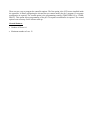


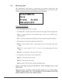


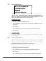

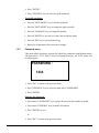


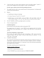


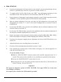

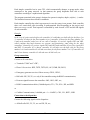


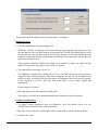

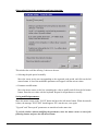

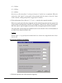


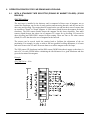

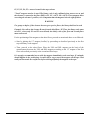
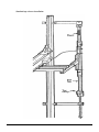
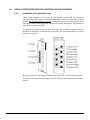
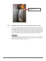
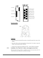
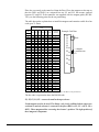


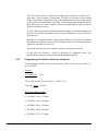
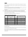


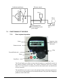


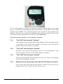
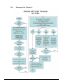

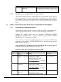

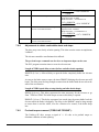


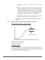


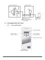
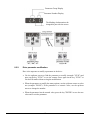
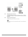


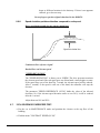

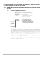


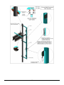
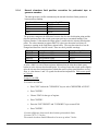
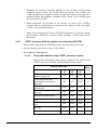


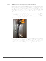


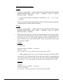


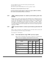
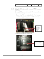
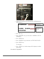


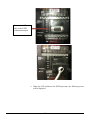
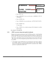
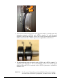


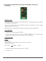


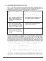


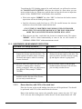


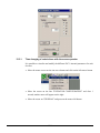
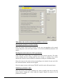

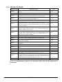

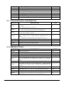


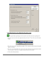


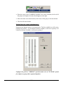


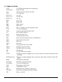


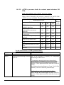
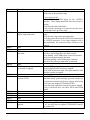


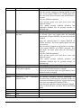
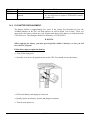


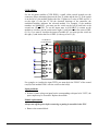


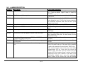
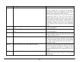
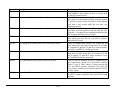
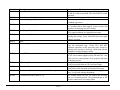

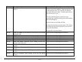


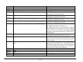
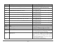
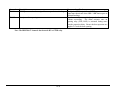
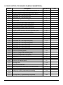


![CASBEE柏[戸建]LR1(PDF形式:1044KB)](http://vs1.manualzilla.com/store/data/006612808_2-5ed36873bbd1c6f331cc4a945d355d8b-150x150.png)