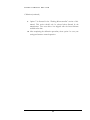
1
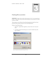
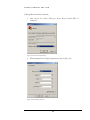
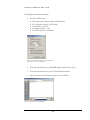
ROTOR CONTROL DXA USB de K4JRG User’sManual ROTOR CONTROL DXA USB , K4JRG User’s Manual V1.06, Rev A1 JR Engineering, Corp 3521 SW 140th Ave Miami, FL 33175 Phone 786.270.1610, x210 • Fax 786.270.1609 eMail: [email protected] Table of Contents Welcome! ..................................................................................... 1 Features ....................................................................................... 2 Specifications............................................................................... 3 Setup ............................................................................................ 4 Calibration .................................................................................. 10 Flashing Microcontroller ............................................................ 13 Warranty and Support ............................................................... 17 Index........................................................................................... 18 R O T O R C O N T R O L D X A U S B Welcome! C ongratulations on your purchase of Rotor Control DXA USB de K4JRG. This device was designed with the goal of providing a functional but inexpensive means of controlling the Yaesu DXA rotors. Our philosophy is to ‘keep it simple’ where we can and above all, make it economical. There are no fancy circuitries here or even LED flashing. In fact, the idea is that you plug the device in, throw it behind your desk and forget about it’s there. The user interface is text based and uses a terminal program as display. You can use this interface to operate the device or, most likely, use it with a logging or spotting program. Rotor Control DXA USB uses a subset of the GS -232 controller protocol which makes it compatible with most software with Yaesu rotor support. If you need assistance with operation or have a comment or suggestion, please don’t hesitate to contact us. Contact information is located in the Warranty and Support section of this manual. 1 R O T O R C O N T R O L D X A U S B Features § 360° fully automatic, software driven rotor azimuth control § 180° Elevation control with azimuth/elevation model § Easy, menu driven calibration - all done in firmware § Full 'plug and play' without opening your rotor control box § Manual rotor controls will operate concurrently § User selected 'Start Delay' to reduce mechanical stress § Auto ramp up/down speeds for smooth start/stop movements § User selected maximum rotational speed § Compatible with most rotor control software that support Yaesu rotors § Menu driven operation using standard terminal program § Self-contained, microcontroller based § Firmware is field upgradeable via simple flash process § 1° movement accuracy if your rotator supports it (most do) § USB connection to your PC. No power supply needed § Custom USB driver makes it compatible with legacy serial port software 2 R O T O R C O N T R O L D X A U S B Specifications Power requirements Provided by USB port Microcontroller Atmel ATmega168 @ 8 MHz 16k bytes Flash memory 512 bytes EEPROM 1k byte SRAM In-system programming with boot loader Field programmable via USB port Hardware ADC, Software DAC Communications 9,600 and 19,200 baud rates 8 data bits None parity 1 stop bit Yaesu GS-232 protocol subset Universal Serial Bus (USB) 3 R O T O R C O N T R O L D X A 1 Chapter U S B Setup Driver Installation: 1. Download the appropriate driver from our website: http://www.k4jrg.org/Site/ham.nsf/RotorControlDrivers?OpenPage 2. If installing the Windows driver, run and extract the downloaded file to temporary directory (for example: c:\temp\k4jrg); you will point to this location when prompted after plugging in the device. 3. Insert the Rotor Control DXA USB connector in a USB port. 4. Select "Install from a list or specific location (Advanced). Figure 1.Virtual COM Port driver installation 4 R O T O R 5. C O N T R O L D X A U S B Select the location where you saved the K4JRG drivers Figure 2. Locate Driver temporary folder 6. On the Hardware Installations prompt, select "Continue Anyway". Figure 3. Continue through this warning 5 R O T O R 7. C O N T R O L D X A U S B Click Finish on the following prompt Figure 4. Composite Device found and installed This bubble pops up in the task bar: 8. You will then get prompted for the actual device installation: K4JRG Rotor Control DXA USB. Select “Install from a list or specific location” and click Next Figure 5. Select "Advanced" and continue 6 R O T O R 9. C O N T R O L D X A U S B Again, select the driver temporary location. Figure 6. Locate temporary driver folder and click Next 10. Click Continue Anyway on the Hardware Installation prompt Figure 7. Continue through this warning 7 R O T O R 11. C O N T R O L D X A U S B Click Finish to complete the install Figure 8. Drive installation completed. Click Finish To verify the driver has been installed and to what COM port: 1. Open the device manager by selecting Start, Run and typing devmgmt.msc Figure 9. Run Device Manager 8 R O T O R 2. C O N T R O L D X A U S B The Device Manager opens up. Expand the "Port" section by clicking on the + sign. Your COM port number might differ from the one shown below Figure 10. Device Manager showing COM & LPT Ports 3. If you haven’t done so already, connect the 6 pin mini DIN connector to your Yaesu DXA rotor controller. The flat end of the male connector faces up. Changing Baud Rate : Rotor Control DXA USB supports 9,600 and 19,200 baud rates. The default factory set speed is 19,200. To change the baud rate: 1. Open Hyperterminal at the current baud rate. You may have to experiment with Hyperterminal between the two speeds if you have changed the default setting at some point. 2. Type B96 for 9,600 or B19 for 19,200 and then press enter. Note that you will not see what you type on the screen. 3. Disconnect Hyperterminal, change it’s baud rate to match your new setting and reconnect. You should see the menu if you enter the UI command. 4. The new setting will be saved to memory so it stays at the new baud rate even if power is removed from the device. 9 R O T O R C O N T R O L D X A 2 Chapter U S B Calibration Rotor Control DXA USB comes preset with generic calibration values that might work for your antenna system setup. However, we strongly encourage you run through this calibration procedure to ensure maximum accuracy and function. 1. Launch your favorite terminal emulation program and set it to Baud rate = 19.200 Bits = 8 Parity = None Stop bits = 1 and select the appropriate COM port as described in the Setup sections, Chapter 1 2. Type the command UI and press Enter. You will be presented with the User Interface and calibration menu. Figure 11. User Interface Main Menu. Activated with the UI command 10 R O T O R C O N T R O L D X A U S B Calibration (continued) 3. Set your rotor heading by selecting 1 from the menu and pressing Enter. You will be prompted to chose your antenna system heading between N=North, S=South, E=East, W=West. Rotor heading refers to where your rotor points to when is resting half way the 360 degree range. For example, if your rotor starts at the left stop of 180 degrees (South), travels over 0 degrees (North) and finishes on 180 degrees (South again), your system is set with a North heading. 4. Select number 2 from the menu and manually move your rotator to its far LEFT stop. Once the rotor has reached its LEFT stop, press Enter to set left. For example, if you selected a North heading, your LEFT stop will be 180 degree (South) 5. Repeat the above procedure for the RIGHT stop by selecting 3 from the menu Note As of this writing, only 360 degree movements are supported so your right stop should be 360 degrees from the left stop in the previous step. 6. Set the maximum rotor speed by selecting 4 from the menu. The rotor speed has an arbitrary range of 1 through 4. Increasing the number will increase the rotor movement top speed. 7. Select number 5 from the menu to set the start delay in seconds. The start delay refers to the time Rotor Control DXA will wait before starting to move the rotator. This feature is helpful in reducing stress to the rotator when reversing direction movement. 8. Menu option 6 allows you to manually enter the antenna azimuth in degrees so you can confirm its accuracy. Note Before you can accurately move the antenna using option 6, you must first save your settings by selecting option 9 and then returning to the UI menu. 11 R O T O R C O N T R O L D X A U S B Calibration (continued) 9. Option 7 is discussed in the “Flashing Microcontroller” section of this manual. This option should only be selected when directed by the manufacturer. Your new device was shipped with the latest firmware available at the time. 10. After completing the calibration procedure, select option 9 to save your settings and return to normal operation. 12 R O T O R C O N T R O L D X A 3 Chapter U S B Flashing Microcontroller WARNING: Complete this procedure when instructed to do so by the manufacturer. Failure to strictly follow this procedure while flashing the microcontroller can render the device unusable. This procedure uses the Windows HyperTerminal application included with these platforms. Make equivalent changes for other terminal applications. Windows HyperTerminal Setup: 1. Launch the HyperTerminal application, usually found in the Accessories folder 2. You will be prompted with a dialog box to enter the terminal setup name. Type “Terminal”. Figure 12. HyperTerminal Setup Name during first time setup. 13 R O T O R C O N T R O L D X A U S B Flashing Microcontroller (continued) 3. Next, choose the serial COM port where Rotor Control DXA is connected. Figure 13. Choose the serial COM port 4. When prompted for COM port parameters, enter 19,200, 8,1,N Figure 14. Set COM port parameter 14 R O T O R C O N T R O L D X A U S B Flashing Microcontroller (continued) 5. Enter the ASCII Setup: § § § § § Disconnect from serial port with Call, Disconnect File, Properties, Settings, ASCII setup Set Line delay = 20 ms Set Character delay = 2 ms Click OK and close the windows Figure 15. ASCII setup window. It's critical that these Parameters are set exactly like shown 6. Press Enter and then type command UI and press the Enter key again. 7. From the main menu shown, choose 7 Flash Microcontroller. 8. Select Transfer, Send Text File and open the new .HEX file Figure 16. Transfer, Send Text File dialog. 15 R O T O R C O N T R O L D X A U S B Flashing Microcontroller (continued) 9. Microcontroller flashing will commence. DO NOT INTERRUPT FLASH PROCESS 10. The microcontroller will echo a ? symbol while it’s receiving the new code. 11. The process will be complete when the microcontroller sends an “X” character. 12. After completion, power cycle Rotor Control DXA by interrupting power for >2 seconds. 16 R O T O R C O N T R O L D X A 4 Chapter U S B Warranty and Support If you’re not completely satisfied with this product, neither are we. We will do our best to make things right for you or we’ll refund your money. For a full purchase price refund, minus shipping and handling, contact us at the address below. Rotor Control DXA is warranted on parts and labor for a period of up to one (1) year after purchase. This warranty is transferable. All parts are covered against defect for one full year except if misused. We have taken steps to ensure this documentation, product interface and use is as simple and clear as possible. Please read this manual thoroughly before requesting support. However, if you have any questions, issue or simply want to make a suggestion or comment, please don’t hesitate to contact us as per below To claim warranty or request support, contact us at: JR Engineering, Corp 3521 SW 140th Ave Miami, FL 33175 Phone 786.270.1610, ext 210 • Fax 786.270.1609 eMail: [email protected] http://www.k4jrg.org 17 R O T O R C O N T R O L D X A Index Maximum Speed, 11 Save settings, 12 Start delay, 11 Terminal, 10 Connections, 9 DIN, 9 Calibration, 10 Features, 2 Flashing Microcontroller, 13 ? symbol, 16 Ascii Setup, 15 HyperTerminal Setup, 13 Power cycle, 16 Process complete, 16 Send File, 15 HEX, 15 WARNING, 13 Specifications, 3 Baud rate, 3 Communications, 3 Microcontroller, 3 Power Requirements, 3 GS-232, 1 Protocol, 1 Setup, 4 User Interface, 1 Warranty and Support, 17 Contact info, 17 Waranty transfer, 17 Warranty period, 17 Whats covered, 17 Baud Rate, 9 Calibration Antenna system heading, 11 18