1
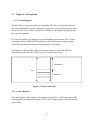
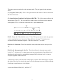
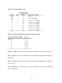
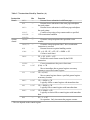
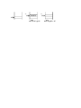
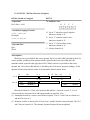
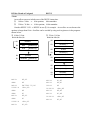
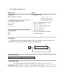
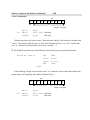
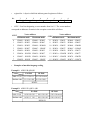
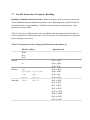
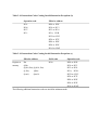
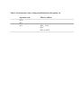
The page registers are used only in the maximum mode. They are ignored in the minimum
mode.
(1) Program Counter (PC): This 16-bit register indicates the address of the next instruction
the CPU will execute.
(2) Status Register/Condition Code Register (SR/CCR): This 16-bit register indicates the
internal state of the CPU. The lower half of the status register is referred to as the condition
code register (CCR): its 8 bits can be accessed as a 1-byte condition code.
SR
CCR
15 14 13 12 11 10 9 8
T
–
–
– –
7
6
5
4 3
2
1
0
I 2 I1 I 0 –
–
–
– N Z V C
Bit 15—Trace (T): When this bit is set to "1," the CPU operates in trace mode and generates
a trace exception after every instruction. When this bit is cleared to "0" instructions are
executed in normal continuous sequence. This bit is cleared to "0" at a reset.
Bits 14 to 11—Reserved: These bits cannot be written, and when read, are always read as
"0."
Bits 10 to 8—Interrupt mask (I2 to I0): These bits indicate the interrupt request mask
level (0 to 7). As shown in 3, an interrupt request is not accepted unless it has a higher level
than the value of the mask. A nonmaskable interrupt (NMI), which has level 8, is always
accepted, regardless of the mask level.
4 indicates the values of the I bits after an interrupt is accepted. When an interrupt is accepted,
the value of bits I2 to I0 is raised to the same level as the interrupt, to prevent a further interrupt
from being accepted unless its level is higher.
A reset sets all three of bits (I2, I1, and I0) to "1."
9