1
Allen-Bradley
Logix5550 Controller
(Cat. No. 1756-L1, -L1Mx)
User Manual
Important User Information
6ROLGVWDWHHTXLSPHQWKDVRSHUDWLRQDOFKDUDFWHULVWLFVGLIIHULQJIURP
WKRVHRIHOHFWURPHFKDQLFDOHTXLSPHQW6DIHW\*XLGHOLQHVIRUWKH
$SSOLFDWLRQ,QVWDOODWLRQDQG0DLQWHQDQFHRI6ROLG6WDWH&RQWUROV
SXEOLFDWLRQ6*,GHVFULEHVVRPHLPSRUWDQWGLIIHUHQFHVEHWZHHQ
VROLGVWDWHHTXLSPHQWDQGKDUGZLUHGHOHFWURPHFKDQLFDOGHYLFHV
%HFDXVHRIWKLVGLIIHUHQFHDQGDOVREHFDXVHRIWKHZLGHYDULHW\RIXVHV
IRUVROLGVWDWHHTXLSPHQWDOOSHUVRQVUHVSRQVLEOHIRUDSSO\LQJWKLV
HTXLSPHQWPXVWVDWLVI\WKHPVHOYHVWKDWHDFKLQWHQGHGDSSOLFDWLRQRI
WKLVHTXLSPHQWLVDFFHSWDEOH
,QQRHYHQWZLOOWKH$OOHQ%UDGOH\&RPSDQ\EHUHVSRQVLEOHRUOLDEOH
IRULQGLUHFWRUFRQVHTXHQWLDOGDPDJHVUHVXOWLQJIURPWKHXVHRU
DSSOLFDWLRQRIWKLVHTXLSPHQW
7KHH[DPSOHVDQGGLDJUDPVLQWKLVPDQXDODUHLQFOXGHGVROHO\IRU
LOOXVWUDWLYHSXUSRVHV%HFDXVHRIWKHPDQ\YDULDEOHVDQGUHTXLUHPHQWV
DVVRFLDWHGZLWKDQ\SDUWLFXODULQVWDOODWLRQWKH$OOHQ%UDGOH\&RPSDQ\
FDQQRWDVVXPHUHVSRQVLELOLW\RUOLDELOLW\IRUDFWXDOXVHEDVHGRQWKH
H[DPSOHVDQGGLDJUDPV
1RSDWHQWOLDELOLW\LVDVVXPHGE\$OOHQ%UDGOH\&RPSDQ\ZLWKUHVSHFW
WRXVHRILQIRUPDWLRQFLUFXLWVHTXLSPHQWRUVRIWZDUHGHVFULEHGLQ
WKLV PDQXDO
5HSURGXFWLRQRIWKHFRQWHQWVRIWKLVPDQXDOLQZKROHRULQSDUW
ZLWKRXWZULWWHQSHUPLVVLRQRIWKH$OOHQ%UDGOH\&RPSDQ\LV
SURKLELWHG
7KURXJKRXWWKLVPDQXDOZHXVHQRWHVWRPDNH\RXDZDUHRIVDIHW\
FRQVLGHUDWLRQV
$77(17,21 ,GHQWLILHVLQIRUPDWLRQDERXWSUDFWLFHV
RUFLUFXPVWDQFHVWKDWFDQOHDGWRSHUVRQDOLQMXU\RU
GHDWKSURSHUW\GDPDJHRUHFRQRPLFORVV
$WWHQWLRQVKHOS\RX
LGHQWLI\DKD]DUG
DYRLGWKHKD]DUG
UHFRJQL]HWKHFRQVHTXHQFHV
,PSRUWDQW,GHQWLILHVLQIRUPDWLRQWKDWLVHVSHFLDOO\LPSRUWDQWIRU
VXFFHVVIXODSSOLFDWLRQDQGXQGHUVWDQGLQJRIWKHSURGXFW
1756-6.5.12 March 1999
6XPPDU\RI&KDQJHV
Introduction
7KLVUHOHDVHRIWKLVGRFXPHQWFRQWDLQVQHZDQGXSGDWHGLQIRUPDWLRQ
7RKHOS\RXILQGWKHQHZDQGXSGDWHGLQIRUPDWLRQORRNIRUFKDQJH
EDUVDVVKRZQQH[WWRWKLVSDUDJUDSK
Updated Information
7KLVGRFXPHQWKDVEHHQXSGDWHGWKURXJKRXW7KHPRVWVLJQLILFDQW
FKDQJHVDUH
For this new/updated information:
See chapter:
Upload/download changes
2
Forcing
11
1756-6.5.12 March 1999
ii
1RWHV
1756-6.5.12 March 1999
3UHIDFH
Using This Manual
7KLVPDQXDOLVRQHRIVHYHUDO&RQWURO/RJL[GRFXPHQWV
Introduction
Task/Goal:
Documents:
Installing the controller and its components
Logix5550 Controller Quick Start, publication 1756-10.1
Logix5550 Memory Board Installation Instructions, publication 1756-5.33
Logix5550 Controller User Manual, publication 1756-6.5.12
Using the controller
You are here
Programming the controller
Logix5550 Controller Instruction Set Reference Manual, publication 1756-6.4.1
Configuring and communicating with digital
I/O modules
Digital Modules User Manual, publication 1756-6.5.8
Configuring and communicating with analog
I/O modules
Analog Modules User Manual, publication 1756-6.5.9
Selecting and installing a chassis
ControlLogix Chassis Installation Instructions, publication 1756-5.69
Selecting and installing a power supply
ControlLogix Power Supply Installation Instructions, publication 1756-5.1
Who Should Use This Manual
7KLVGRFXPHQWSURYLGHVDSURJUDPPHUZLWKLQIRUPDWLRQDERXWKRZ
WKH/RJL[FRQWUROOHU
VWRUHVDQGSURFHVVHVGDWD
RSHUDWHV
FRPPXQLFDWHVZLWKRWKHUPRGXOHV
SURFHVVHVDQGKDQGOHVIDXOWLQIRUPDWLRQ
1756-6.5.12 March 1999
ii
Using This Manual
Purpose of This Manual
7KLVPDQXDOLVLQWHQGHGWRKHOS\RXGHVLJQDQGRSHUDWHDV\VWHP
XVLQJD/RJL[FRQWUROOHU7KHILUVWFKDSWHULQWKLVPDQXDO
SURYLGHVWKHVWHSVDQGLQIRUPDWLRQ\RXQHHGWRJHWVWDUWHG
8VHWKHUHPDLQGHURIWKLVPDQXDOWRKHOS\RX
Conventions and Related Terms
1756-6.5.12 March 1999
ZRUNZLWKFRQWUROOHUSURMHFWV
FRQILJXUH,2PRGXOHV
RUJDQL]HGDWD
GHYHORSSURJUDPV
FRQILJXUHSURGXFHGDQGFRQVXPHGGDWD
DFFRXQWIRUFRPPXQLFDWLRQFRQQHFWLRQV
FRPPXQLFDWLRQRYHUDVHULDOQHWZRUN
FRPPXQLFDWHRYHURWKHUQHWZRUNV
LGHQWLI\DQGSURFHVVFRQWUROOHUIDXOWV
7KLVPDQXDOLQFOXGHVDJORVVDU\WRGHILQHFRPPRQWHUPV
Table of Contents
Getting Started
Chapter 1
Using This Chapter . . . . . . . . . . . . . . . . . . . . . . . . . . . . . 1-1
Installing the Controller . . . . . . . . . . . . . . . . . . . . . . . . . . 1-2
Prepare the controller . . . . . . . . . . . . . . . . . . . . . . . . . 1-3
Install the controller . . . . . . . . . . . . . . . . . . . . . . . . . . 1-3
Creating and Downloading a Project . . . . . . . . . . . . . . . . 1-4
Create a project . . . . . . . . . . . . . . . . . . . . . . . . . . . . . 1-5
Changing project properties . . . . . . . . . . . . . . . . . . . . 1-6
Adding a local input module . . . . . . . . . . . . . . . . . . . . 1-7
Adding a local output module . . . . . . . . . . . . . . . . . . . 1-9
Changing module properties . . . . . . . . . . . . . . . . . . . 1-11
Viewing I/O tags . . . . . . . . . . . . . . . . . . . . . . . . . . . . 1-12
Creating other tags . . . . . . . . . . . . . . . . . . . . . . . . . . 1-13
Documenting I/O with alias tags . . . . . . . . . . . . . . . . 1-14
Enter logic. . . . . . . . . . . . . . . . . . . . . . . . . . . . . . . . . 1-16
Download a project . . . . . . . . . . . . . . . . . . . . . . . . . . 1-18
Viewing program scan time. . . . . . . . . . . . . . . . . . . . 1-21
Viewing controller memory usage . . . . . . . . . . . . . . . 1-22
What To Do Next . . . . . . . . . . . . . . . . . . . . . . . . . . . . . . 1-22
Working with Projects
Chapter 2
Using This Chapter . . . . . . . . . . . . . . . . . . . . . . . . . . . . . 2-1
Creating a Project . . . . . . . . . . . . . . . . . . . . . . . . . . . . . . 2-1
Naming controllers . . . . . . . . . . . . . . . . . . . . . . . . . . . 2-2
Changing Project Properties . . . . . . . . . . . . . . . . . . . . . . 2-2
Working with the Controller Organizer . . . . . . . . . . . . . . . 2-3
Saving Your Project. . . . . . . . . . . . . . . . . . . . . . . . . . . . . 2-4
Uploading From the Controller. . . . . . . . . . . . . . . . . . . . . 2-4
Using Coordinated System Time . . . . . . . . . . . . . . . . . . . 2-5
Configuring I/O Modules
Chapter 3
Using This Chapter . . . . . . . . . . . . . . . . . . . . . . . . . . . . . 3-1
Introduction . . . . . . . . . . . . . . . . . . . . . . . . . . . . . . . . . . 3-1
Logic Scanning . . . . . . . . . . . . . . . . . . . . . . . . . . . . . . . . 3-2
Defining I/O Updates . . . . . . . . . . . . . . . . . . . . . . . . . . . . 3-2
How an I/O module uses COS . . . . . . . . . . . . . . . . . . . 3-2
How an I/O module uses RPI . . . . . . . . . . . . . . . . . . . . 3-3
When an analog module uses RTS. . . . . . . . . . . . . . . . 3-3
How I/O Modules Operate . . . . . . . . . . . . . . . . . . . . . . . . 3-3
1756-6.5.12 March1999
toc–ii
Table of Contents
Configuring Local I/O. . . . . . . . . . . . . . . . . . . . . . . . . . . . 3-4
Naming modules . . . . . . . . . . . . . . . . . . . . . . . . . . . . . 3-5
Electronic keying . . . . . . . . . . . . . . . . . . . . . . . . . . . . . 3-6
Configuring communication format . . . . . . . . . . . . . . . 3-7
Selecting controller ownership . . . . . . . . . . . . . . . . . . 3-8
Inhibiting module operation . . . . . . . . . . . . . . . . . . . . . 3-9
Configuring I/O in a Remote Chassis . . . . . . . . . . . . . . . 3-11
Changing Configuration Information . . . . . . . . . . . . . . . 3-15
Accessing I/O . . . . . . . . . . . . . . . . . . . . . . . . . . . . . . . . 3-16
Example of local addressing . . . . . . . . . . . . . . . . . . . 3-17
Example of remote addressing . . . . . . . . . . . . . . . . . 3-18
Defining aliases. . . . . . . . . . . . . . . . . . . . . . . . . . . . . 3-19
Viewing Module Fault Information . . . . . . . . . . . . . . . . . 3-19
Using the programming software to view I/O faults . . 3-21
Using logic to monitor I/O faults. . . . . . . . . . . . . . . . . 3-22
Organizing Data
1756-6.5.12 March1999
Chapter 4
Using This Chapter . . . . . . . . . . . . . . . . . . . . . . . . . . . . . 4-1
How the Controller Stores Data . . . . . . . . . . . . . . . . . . . . 4-1
Creating Tags . . . . . . . . . . . . . . . . . . . . . . . . . . . . . . . . . 4-2
Data types. . . . . . . . . . . . . . . . . . . . . . . . . . . . . . . . . . 4-3
Naming tags . . . . . . . . . . . . . . . . . . . . . . . . . . . . . . . . 4-4
Entering tags. . . . . . . . . . . . . . . . . . . . . . . . . . . . . . . . 4-4
Using Base Tags . . . . . . . . . . . . . . . . . . . . . . . . . . . . . . . 4-6
Memory allocation for base tags . . . . . . . . . . . . . . . . . 4-6
Data type conversions . . . . . . . . . . . . . . . . . . . . . . . . . 4-8
Specifying bits. . . . . . . . . . . . . . . . . . . . . . . . . . . . . . . 4-8
Using Structures . . . . . . . . . . . . . . . . . . . . . . . . . . . . . . . 4-9
Predefined structures . . . . . . . . . . . . . . . . . . . . . . . . 4-10
Module-defined structure . . . . . . . . . . . . . . . . . . . . . 4-10
User-defined structure. . . . . . . . . . . . . . . . . . . . . . . . 4-10
Memory allocation for user-defined structures. . . . . . 4-11
Referencing members within a structure . . . . . . . . . . 4-12
Viewing an Array as a Collection of Elements . . . . . . . . 4-13
Indexing through arrays. . . . . . . . . . . . . . . . . . . . . . . 4-14
Specifying Bits Within Arrays . . . . . . . . . . . . . . . . . . . 4-15
Viewing an Array as a Block of Memory. . . . . . . . . . . . . 4-15
How the controller stores array data . . . . . . . . . . . . . 4-16
Varying a dimension . . . . . . . . . . . . . . . . . . . . . . . . . 4-17
Memory Allocation for Arrays . . . . . . . . . . . . . . . . . . . . 4-17
Aliasing Tags. . . . . . . . . . . . . . . . . . . . . . . . . . . . . . . . . 4-19
Scoping Tags . . . . . . . . . . . . . . . . . . . . . . . . . . . . . . . . 4-20
Scoping tags local to a program . . . . . . . . . . . . . . . . 4-21
Scoping tags global to a controller. . . . . . . . . . . . . . . 4-21
Table of Contents
toc–iii
Developing Programs
Chapter 5
Using This Chapter . . . . . . . . . . . . . . . . . . . . . . . . . . . . . 5-1
Organizing Projects . . . . . . . . . . . . . . . . . . . . . . . . . . . . . 5-1
Defining Tasks . . . . . . . . . . . . . . . . . . . . . . . . . . . . . . . . 5-2
Using a continuous task . . . . . . . . . . . . . . . . . . . . . . . 5-3
Using a periodic task . . . . . . . . . . . . . . . . . . . . . . . . . . 5-3
Creating tasks . . . . . . . . . . . . . . . . . . . . . . . . . . . . . . . 5-5
Naming tasks . . . . . . . . . . . . . . . . . . . . . . . . . . . . . . . 5-6
Configuring tasks . . . . . . . . . . . . . . . . . . . . . . . . . . . . 5-6
Setting the task watchdog . . . . . . . . . . . . . . . . . . . . . . 5-8
Avoiding periodic task overlap . . . . . . . . . . . . . . . . . . . 5-8
Defining Programs . . . . . . . . . . . . . . . . . . . . . . . . . . . . . 5-8
Creating programs. . . . . . . . . . . . . . . . . . . . . . . . . . . . 5-9
Naming programs . . . . . . . . . . . . . . . . . . . . . . . . . . . . 5-9
Configuring programs . . . . . . . . . . . . . . . . . . . . . . . . 5-10
Defining Routines . . . . . . . . . . . . . . . . . . . . . . . . . . . . . 5-11
Creating routines. . . . . . . . . . . . . . . . . . . . . . . . . . . . 5-11
Naming routines . . . . . . . . . . . . . . . . . . . . . . . . . . . . 5-12
Configuring routines . . . . . . . . . . . . . . . . . . . . . . . . . 5-12
Entering Ladder Logic . . . . . . . . . . . . . . . . . . . . . . . . . . 5-13
Entering branches . . . . . . . . . . . . . . . . . . . . . . . . . . . 5-14
Scheduling System Overhead . . . . . . . . . . . . . . . . . . . . 5-15
Downloading a Project . . . . . . . . . . . . . . . . . . . . . . . . . 5-16
Communicating with Other
Controllers
Chapter 6
Using This Chapter . . . . . . . . . . . . . . . . . . . . . . . . . . . . . 6-1
Using MSG Instructions . . . . . . . . . . . . . . . . . . . . . . . . . . 6-1
Communicating with another Logix5550 controller . . . 6-1
Communicating with other processors. . . . . . . . . . . . . 6-2
Mapping addresses . . . . . . . . . . . . . . . . . . . . . . . . . . . 6-4
Using Produced and Consumed Tags . . . . . . . . . . . . . . . 6-6
Processing produced and consumed tags . . . . . . . . . . 6-7
Maximum number of produced and consumed tags . . 6-8
Planning to Support Produced and Consumed Tags. . . . . 6-9
Identifying another local controller. . . . . . . . . . . . . . . 6-10
Identifying a remote controller . . . . . . . . . . . . . . . . . . 6-10
Producing a Tag . . . . . . . . . . . . . . . . . . . . . . . . . . . . . . 6-12
Consuming a Tag . . . . . . . . . . . . . . . . . . . . . . . . . . . . . 6-14
Sending Large Arrays of Data . . . . . . . . . . . . . . . . . . . . 6-17
1756-6.5.12 March1999
toc–iv
Table of Contents
Allocating Communication
Connections
Chapter 7
Communicating with Devices on
a Serial Link
Chapter 8
Communicating with a
Workstation
Chapter 9
1756-6.5.12 March1999
Using This Chapter . . . . . . . . . . . . . . . . . . . . . . . . . . . . . 7-1
How the ControlLogix System Uses Connections . . . . . . . 7-1
Determining Connections for I/O Modules . . . . . . . . . . . . 7-2
Direct connections for I/O modules . . . . . . . . . . . . . . . 7-2
Rack optimized connections for I/O modules . . . . . . . . 7-4
Combining direct and rack optimized connections . . . . 7-5
Determining Connections for Produced/Consumed Tags . 7-6
Connections for produced tags . . . . . . . . . . . . . . . . . . 7-6
Optimizing produced tags . . . . . . . . . . . . . . . . . . . . . . 7-7
Connections for consumed tags. . . . . . . . . . . . . . . . . . 7-7
Determining Connections for Messaging . . . . . . . . . . . . . 7-7
Determining Total Connection Requirements . . . . . . . . . . 7-8
Using This Chapter . . . . . . . . . . . . . . . . . . . . . . . . . . . . . 8-1
Using RS-232 . . . . . . . . . . . . . . . . . . . . . . . . . . . . . . . . . 8-1
Connecting to the Serial Port . . . . . . . . . . . . . . . . . . . . . . 8-2
Configuring the controller to use the serial port . . . . . . 8-3
Using the DF1 Serial Protocol . . . . . . . . . . . . . . . . . . . . . 8-4
Master/slave communication methods . . . . . . . . . . . . 8-5
Configuring Serial Communications. . . . . . . . . . . . . . . . . 8-5
Configuring a DF1 point-to-point station . . . . . . . . . . . 8-6
Configuring a DF1 slave station . . . . . . . . . . . . . . . . . . 8-7
Configuring a DF1 master station . . . . . . . . . . . . . . . . 8-8
If you choose one of the standard polling modes . . . . . 8-9
Using This Chapter . . . . . . . . . . . . . . . . . . . . . . . . . . . . . 9-1
Configuring Communications to the Controller. . . . . . . . . 9-1
Defining Connection Paths . . . . . . . . . . . . . . . . . . . . . . . 9-2
Connection path examples . . . . . . . . . . . . . . . . . . . . . 9-4
Table of Contents
Integrating Motion
toc–v
Chapter 10
Using This Chapter . . . . . . . . . . . . . . . . . . . . . . . . . . . . 10-1
Introduction. . . . . . . . . . . . . . . . . . . . . . . . . . . . . . . . . . 10-1
Developing a Motion Control Application Program . . . . . 10-2
Selecting the master controller . . . . . . . . . . . . . . . . . 10-2
Adding a 1756-M02AE module . . . . . . . . . . . . . . . . . 10-3
Naming an axis . . . . . . . . . . . . . . . . . . . . . . . . . . . . . 10-4
Configuring a servo axis . . . . . . . . . . . . . . . . . . . . . . 10-5
Running hookup diagnostics and auto tuning. . . . . . 10-11
Writing a Motion Application Program . . . . . . . . . . . . . 10-12
Understanding the MOTION_INSTRUCTION tag . . . . 10-13
Using motion status and configuration parameters . 10-13
Modifying motion configuration parameters. . . . . . . 10-14
Handling motion faults. . . . . . . . . . . . . . . . . . . . . . . 10-14
Understanding errors. . . . . . . . . . . . . . . . . . . . . . . . 10-14
Understanding minor/major faults . . . . . . . . . . . . . . 10-14
Understanding a programming example . . . . . . . . . 10-15
Forcing
Chapter 11
Using This Chapter . . . . . . . . . . . . . . . . . . . . . . . . . . . . 11-1
Forcing . . . . . . . . . . . . . . . . . . . . . . . . . . . . . . . . . . . . . 11-1
Entering Forces . . . . . . . . . . . . . . . . . . . . . . . . . . . . . . . 11-2
Entering forces from the data monitor . . . . . . . . . . . . 11-2
Entering forces from the ladder editor . . . . . . . . . . . . 11-3
Enabling Forces. . . . . . . . . . . . . . . . . . . . . . . . . . . . . . . 11-4
Disabling Forces . . . . . . . . . . . . . . . . . . . . . . . . . . . . . . 11-5
Removing Forces . . . . . . . . . . . . . . . . . . . . . . . . . . . . . 11-5
Monitoring Forces . . . . . . . . . . . . . . . . . . . . . . . . . . . . . 11-6
Handling Controller Faults
Chapter 12
Using This Chapter . . . . . . . . . . . . . . . . . . . . . . . . . . . . 12-1
Understanding Controller Faults. . . . . . . . . . . . . . . . . . . 12-1
Viewing Controller Faults. . . . . . . . . . . . . . . . . . . . . . . . 12-2
Monitoring I/O Faults . . . . . . . . . . . . . . . . . . . . . . . . . . . 12-2
Handling Hardware Faults . . . . . . . . . . . . . . . . . . . . . . . 12-3
Processing Minor Faults . . . . . . . . . . . . . . . . . . . . . . . . 12-3
Processing instruction-execution minor faults . . . . . . 12-4
Writing logic for instruction-execution minor faults . . 12-5
Processing other minor faults . . . . . . . . . . . . . . . . . . 12-6
Writing logic for other minor faults. . . . . . . . . . . . . . . 12-7
Minor Fault Types and Codes . . . . . . . . . . . . . . . . . . . . 12-8
Processing Major Faults . . . . . . . . . . . . . . . . . . . . . . . . 12-9
Writing logic for a major fault . . . . . . . . . . . . . . . . . 12-12
Major Fault Types and Codes . . . . . . . . . . . . . . . . . . . 12-14
Creating a Program Fault Routine . . . . . . . . . . . . . . . . 12-16
Creating the Controller Fault Handler. . . . . . . . . . . . . . 12-16
1756-6.5.12 March1999
toc–vi
Table of Contents
Creating a program for the controller fault handler. . 12-17
Naming programs . . . . . . . . . . . . . . . . . . . . . . . . . . 12-17
Selecting an unscheduled program . . . . . . . . . . . . . 12-17
Configuring programs . . . . . . . . . . . . . . . . . . . . . . . 12-18
Creating routines. . . . . . . . . . . . . . . . . . . . . . . . . . . 12-19
Naming routines . . . . . . . . . . . . . . . . . . . . . . . . . . . 12-19
Accessing the FAULTLOG . . . . . . . . . . . . . . . . . . . . . . 12-20
MajorFaultBits structure . . . . . . . . . . . . . . . . . . . . . 12-20
MinorFaultBits structure . . . . . . . . . . . . . . . . . . . . . 12-20
Preparing a Power-Up Program
Chapter 13
Using This Chapter . . . . . . . . . . . . . . . . . . . . . . . . . . . . 13-1
How the Controller Powers Up in Run Mode. . . . . . . . . . 13-1
Processing the power-up handler . . . . . . . . . . . . . . . 13-2
Creating the Power-Up Handler . . . . . . . . . . . . . . . . . . . 13-3
Creating a program for the power-up handler . . . . . . 13-3
Naming programs . . . . . . . . . . . . . . . . . . . . . . . . . . . 13-3
Selecting an unscheduled program . . . . . . . . . . . . . . 13-4
Configuring programs . . . . . . . . . . . . . . . . . . . . . . . . 13-4
Creating routines. . . . . . . . . . . . . . . . . . . . . . . . . . . . 13-5
Naming routines . . . . . . . . . . . . . . . . . . . . . . . . . . . . 13-6
Clearing the Major Fault . . . . . . . . . . . . . . . . . . . . . . . . 13-6
Troubleshooting
Appendix A
Using This Appendix . . . . . . . . . . . . . . . . . . . . . . . . . . . . A-1
Identifying Controller Components. . . . . . . . . . . . . . . . . . A-1
Monitoring Controller Status LEDs . . . . . . . . . . . . . . . . . . A-2
Determining which modules are not responding . . . . . A-3
Monitoring Controller Status . . . . . . . . . . . . . . . . . . . . . . A-5
Viewing status through the programming software . . . A-5
Monitoring status flags . . . . . . . . . . . . . . . . . . . . . . . . A-6
Using GSV/SSV instructions . . . . . . . . . . . . . . . . . . . . . A-6
Changing Controller Mode . . . . . . . . . . . . . . . . . . . . . . . . A-8
Examining Controller Prescan Operations . . . . . . . . . . . . A-9
Instructions with unique prescan operations . . . . . . . . A-9
Recovering from prescan errors. . . . . . . . . . . . . . . . . A-10
1756-6.5.12 March1999
Table of Contents
IEC1131-3 Compliance
toc–vii
Appendix B
Using This Appendix . . . . . . . . . . . . . . . . . . . . . . . . . . . . B-1
Introduction. . . . . . . . . . . . . . . . . . . . . . . . . . . . . . . . . . . B-1
Operating System . . . . . . . . . . . . . . . . . . . . . . . . . . . . . . B-2
Data Definitions. . . . . . . . . . . . . . . . . . . . . . . . . . . . . . . . B-2
Programming Languages . . . . . . . . . . . . . . . . . . . . . . . . B-3
Instruction Set. . . . . . . . . . . . . . . . . . . . . . . . . . . . . . . . . B-3
IEC1131-3 Program Portability . . . . . . . . . . . . . . . . . . . . B-4
IEC Compliance Tables . . . . . . . . . . . . . . . . . . . . . . . . . . B-4
Specifications
Appendix C
Logix5550 Controller. . . . . . . . . . . . . . . . . . . . . . . . . . . . C-1
Logix5550 Memory Board . . . . . . . . . . . . . . . . . . . . . . . . C-2
1756-CP3 Serial Cable Pinouts . . . . . . . . . . . . . . . . . . . . C-3
1756-BA1 Battery . . . . . . . . . . . . . . . . . . . . . . . . . . . . . . C-3
1756-M0A2E Motion Module. . . . . . . . . . . . . . . . . . . . . . C-4
Glossary
1756-6.5.12 March1999
toc–viii
Table of Contents
1RWHV
1756-6.5.12 March1999
Chapter
1
Getting Started
Using This Chapter
7KLVFKDSWHULQWURGXFHVWKH/RJL[FRQWUROOHUDQGSURYLGHVD
TXLFNRYHUYLHZRQLQVWDOOLQJWKHFRQWUROOHUDQGRQFUHDWLQJDQG
GRZQORDGLQJDSURMHFW7KHVWHSVLQWKLVFKDSWHULQWURGXFHWKHEDVLF
DVSHFWVRIWKH/RJL[FRQWUROOHUDQGUHIHU\RXWRODWHUFKDSWHUVLQ
WKLVPDQXDOIRUPRUHGHWDLOV
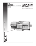
7KH/RJL[FRQWUROOHUVXLWVDZLGHUDQJHRIFRQWURODSSOLFDWLRQV
E\VXSSRUWLQJ
PXOWLSOHFRQWUROOHUVLQRQH&RQWURO/RJL[FKDVVLV
FRQWUROOHUVGLVWULEXWHGDFURVVPXOWLSOHFKDVVLV
VFKHGXOHGSURFHVVRUWRSURFHVVRUFRPPXQLFDWLRQV
PXOWLSOHFRQWUROOHUVWKDWVKDUHWKHVDPH,2PRGXOHVDQG
FRPPXQLFDWLRQVPRGXOHV
Logix5550 Controller
ControlNet
Remote I/O
DH+
ControlLogix Chassis
PanelView
PLC-5 Processor
1771-ASB
SLC 5/04 Processor
PLC-5 Processor
PLC-5 Processor
Block I/O
1747-ASB
FLEX I/O
1336T Drive
30169
1756-6.5.12 March 1999
1-2
Getting Started
Installing the Controller
7KHIROORZLQJGLUHFWLRQVVXPPDUL]HWKHSURFHGXUHIRULQVWDOOLQJD
/RJL[FRQWUROOHU)RUGHWDLOVVHHWKH/RJL[&RQWUROOHU
4XLFN6WDUWSXEOLFDWLRQZKLFKVKLSVZLWKWKHFRQWUROOHU
7DNHWKHVHSUHFDXWLRQVWRJXDUGDJDLQVW(6'GDPDJH
$77(17,21 (OHFWURVWDWLFGLVFKDUJHFDQGDPDJHWKH
FRPSRQHQWV)ROORZWKHVHJXLGHOLQHV
WRXFKDJURXQGHGREMHFWWRGLVFKDUJHSRWHQWLDOVWDWLF
ZHDUDQDSSURYHGJURXQGLQJZULVWVWUDS
GRQRWWRXFKFRQQHFWRUVRUFRQQHFWRURQFRPSRQHQW
ERDUGV
GRQRWWRXFKFLUFXLWFRPSRQHQWVLQVLGHWKH
FRQWUROOHU
LIDYDLODEOHXVHDVWDWLFVDIHZRUNVWDWLRQ
ZKHQQRWLQXVHVWRUHHDFKFRPSRQHQWLQWKH
DQWLVWDWLFSDFNDJLQJLQZKLFKLWZDVVKLSSHG
<RXFDQLQVWDOORUUHPRYH&RQWURO/RJL[V\VWHPFRPSRQHQWVZKLOH
FKDVVLVSRZHULVDSSOLHGDQGWKHV\VWHPLVRSHUDWLQJ,I\RXUHPRYH
WKHFRQWUROOHUDOOWKHGHYLFHVRZQHGE\WKHFRQWUROOHUJRWRWKHLU
FRQILJXUHGIDXOWHGVWDWH
$77(17,21 :KHQ\RXLQVHUWRUUHPRYHDPRGXOH
ZKLOHEDFNSODQHSRZHULVRQDQHOHFWULFDODUFPD\RFFXU
$QHOHFWULFDODUFFDQFDXVHSHUVRQDOLQMXU\RUSURSHUW\
GDPDJH E\
VHQGLQJDQHUURQHRXVVLJQDOWR\RXUV\VWHP¶V
DFWXDWRUVFDXVLQJXQLQWHQGHGPDFKLQHPRWLRQRU
ORVVRISURFHVV FRQWURO
FDXVLQJDQH[SORVLRQLQDKD]DUGRXVHQYLURQPHQW
5HSHDWHGHOHFWULFDODUFLQJFDXVHVH[FHVVLYHZHDUWR
FRQWDFWVRQERWKWKHPRGXOHDQGLWVPDWLQJFRQQHFWRU
:RUQFRQWDFWVPD\FUHDWHHOHFWULFDOUHVLVWDQFHWKDWFDQ
DIIHFWPRGXOH RSHUDWLRQ
1756-6.5.12 March 1999
Getting Started
1-3
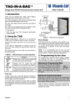
Prepare the controller
,QVWDOOWKHEDWWHU\
top
middle
bottom
30167
no connection
black lead (-)
red lead (+)
Store the lithium battery in a cool, dry environment,
typically 20° C to 25° C (68° F to 77° F) and 40% to
60% relative humidity. Store the batteries in the
original container, away from flammable materials.
Attention: Only install a 1756-BA1 battery.
)RUPRUHLQIRUPDWLRQVHH*XLGHOLQHVIRU+DQGOLQJ/LWKLXP
%DWWHULHVSXEOLFDWLRQ
,QVWDOOWKHPHPRU\H[SDQVLRQERDUGLIDQ\
a.
Remove the side plate.
b. Attach the memory board.
40017
40018
7KH/RJL[FRQWUROOHUFDQEHSXUFKDVHGZLWKDPHPRU\
H[SDQVLRQERDUGDOUHDG\LQVWDOOHGFDWDORJQXPEHUV/0
/0RU/0
)RUPRUHLQIRUPDWLRQVHHWKH/RJL[0HPRU\%RDUG
,QVWDOODWLRQ,QVWUXFWLRQVSXEOLFDWLRQ
Install the controller
<RXFDQSODFHWKH/RJL[FRQWUROOHULQDQ\VORW<RXFDQXVH
PXOWLSOH/RJL[FRQWUROOHUVLQWKHVDPH FKDVVLV7KHWRWDOQXPEHU
RIPRGXOHVLQDFKDVVLVGHSHQGVRQSRZHUVXSSO\FDSDFLW\
1. Align the circuit board with the top and bottom guides in the chassis.
2. Slide the module into the chassis.
3. Make sure the module properly connects to the chassis backplane.
20880
7KHFRQWUROOHULVIXOO\LQVWDOOHGZKHQLWLVIOXVKZLWKWKHSRZHUVXSSO\
RURWKHUIXOO\LQVWDOOHGPRGXOHVDQGWKHWRSDQGERWWRPODWFKHV
DUH HQJDJHG
1756-6.5.12 March 1999
1-4
Getting Started
7KHIROORZLQJGLDJUDPLOOXVWUDWHVWKHVWHSV\RXIROORZWRFUHDWHDQG
GRZQORDGDSURMHFW7KHUHPDLQGHURIWKLVTXLFNVWDUWSURYLGHV
H[DPSOHVRIHDFKVWHSZLWKUHIHUHQFHVWRRWKHUFKDSWHUVLQWKLV
PDQXDOIRUPRUHGHWDLOV
Creating and Downloading
a Project
System setup for this quick start:
Create a project
goto page 1-5
1756-L1
slot 3
Configure
I/O modules
empty
slot 0
goto page 1-7
1756-OB16E
slot 2
You need:
• RSLogix5000 programming software
• RSLinx communication software
• DF1 point-to-point, serial connection from the workstation
to the controller (using 1756-CP3 cable)
Create tags
goto page 1-13
If you don’t have this hardware, you can still follow the steps
in this quick start. Substitute the I/O modules you have for
the ones in the quick start and make the appropriate changes.
Enter logic
goto page 1-16
Download
a project
goto page 1-18
1756-6.5.12 March 1999
1756-IB16
slot 1
View status
goto page 1-21
Getting Started
1-5
Create a project
To follow the steps in this quick start, RSLogix5000 programming software must already be installed and running.
1.
Create a project
Select File → New to create a project.
see chapter 2
2.
Define the project.
The software uses the project name you enter with an .ACD extension to store your project.
You must enter a name.
Select the chassis type and specify
the slot number of the controller.
(You will have to change the default values.)
Describe the project (optional).
Select where to store the project
(typically use the default directory).
Click OK.
The software displays:
controller organizer
1756-6.5.12 March 1999
1-6
Getting Started
Changing project properties
1.
View properties for Controller quick_start.
Create a project
see chapter 2
A. Place the cursor over the Controller quick_start folder.
B. Click the right mouse button and select Properties.
2.
View the General tab.
The screen defaults to the General tab.
Verify that the controller settings are
correct. Make changes if necessary.
Click OK.
From this tab:
You can:
General
modify the controller name, description, and controller properties for the
current project
online only
view and edit the controller’s wall clock time and the coordinated system time status.
configure communication information that is stored with the project file
view and configure the serial port on the controller
configure the serial port for:
• DF1 point-to-point
• DF1 slave
• DF1 master
online only
view any major faults that have occurred on the controller
online only
view any minor faults that have occurred on the controller
some features are online only
view and edit advanced controller properties, which include the system fault program,
the power loss program, and system overhead time slice
view information about the project file
Date/Time
Communications
Serial Port
Serial Port Protocol
Major Faults
Minor Faults
Advanced
File
1756-6.5.12 March 1999
Getting Started
1-7
Adding a local input module
1.
Create a new module.
Configure
I/O modules
see chapter 3
A. Place the cursor over the I/O Configuration folder.
B. Click the right mouse button and select New Module
2.
Select an input module to add.
Select a catalog number.
For this quick start example, select 1756-IB16.
Click OK.
continued
1756-6.5.12 March 1999
1-8
Getting Started
Adding a local input module (continued)
3.
Identify the input module.
These screens are specific to the 1756-IB16 input module.
You should enter a name.
Verify the slot number.
Configure
I/O modules
see chapter 3
Describe the module (optional).
Select the communication format.
Specify electronic keying.
Click Next.
4.
Use the Create wizard to configure the input module.
Use default values for this quick start example.
If you do not want to page through each screen in the
Create wizard, click Finish to create the module using
default values.
Click Next.
Click Next.
Click Next.
Click Finish.
continued
1756-6.5.12 March 1999
Getting Started
1-9
Adding a local output module
1.
Create a new module.
Configure
I/O modules
see chapter 3
A. Place the cursor over the I/O Configuration folder.
B. Click the right mouse button and select New Module
2.
Select an output module to add.
Select a catalog number.
For this quick start example, select 1756-OB16E.
Click OK.
continued
1756-6.5.12 March 1999
1-10
Getting Started
Adding a local output module (continued)
3.
Identify the output module.
These screens are specific to the 1756-OB16E output module.
You should enter a name.
Verify the slot number.
Configure
I/O modules
see chapter 3
Describe the module (optional).
Select the communication format.
Specify electronic keying.
Click Next.
4.
Use the Create wizard to configure the output module.
Use default values for this quick start example.
If you do not want to page through each screen in the
Create wizard, click Finish to create the module using
default values.
Click Next.
Click Next.
Click Next.
Click Next.
Click Finish.
continued
1756-6.5.12 March 1999
Getting Started
1-11
Changing module properties
1.
View properties for the module.
Configure
I/O modules
see chapter 3
A. Place the cursor over the 1756-IB16 module.
B. Click the right mouse button and select Properties
2.
View the General tab.
The screen defaults to the General tab.
Verify that the module settings are
correct. Make changes if necessary.
Click OK.
7KHWDEVWKDWDSSHDUGHSHQGRQWKHW\SHRIPRGXOH
From this tab:
You can:
General
Connection
modify the properties for the current module
define controller to module behavior:
• select requested packet interval
• choose to inhibit the connection to the module
• configure the controller so loss of connection generates a major fault
• view module faults (online only)
online only
view module identification and status information
reset module to power-up state
configure the module
online only
view information about module’s communication over the backplane
clear module faults
set transmit retry limit
Module Info
Configuration
Backplane
1756-6.5.12 March 1999
1-12
Getting Started
Viewing I/O tags
1.
View the module-defined tags.
Configure
I/O modules
see chapter 3
Place the cursor on the Controller Tags folder
and double-click.
The software displays the module-defined tags for the I/O modules you created.
The 1756-IB16 input
module is in slot 1.
The 1756-OB16E output
module is in slot 2.
Click the Edit Tags tab.
continued
1756-6.5.12 March 1999
Getting Started
1-13
Creating other tags
1.
Create a tag.
Create tags
see chapter 4
Enter the name of the new tag.
2.
Tab to this column and
select the data type.
Select the data type.
Select TIMER.
Click OK.
Press Enter.
The software displays the tag.
Click + to display the members
of the TIMER structure.
You might have to resize the column to see the tag extensions.
continued
1756-6.5.12 March 1999
1-14
Getting Started
Documenting I/O with alias tags
1.
Create an alias tag input_1 for Local:1:I.Data.1.
Create tags
see chapter 4
Enter the name of the tag.
2.
Tab here or click in the box.
Click here to select tag to reference.
Select an input data word.
A. Click on the input data structure.
B. Click + to display the members of the structure.
C. Click the input data word
Click here to select a bit.
2.
Select a specific bit.
Click on the bit.
Press Enter.
continued
1756-6.5.12 March 1999
Getting Started
1-15
Documenting I/O with alias tags (continued)
4.
Repeat steps 1 and 2 above to create an alias tag output_1 for Local:2:O.Data.1
Create tags
The software displays the alias tags.
see chapter 4
1756-6.5.12 March 1999
1-16
Getting Started
Enter logic
1.
Use default task, program, and routine.
When you created the project, the software
automatically created a MainTask, MainProgram, and
MainRoutine. Use these defaults for the quick start.
Double-click MainRoutine.
The software displays an empty routine.
2.
Enter an XIO instruction.
Drag and drop the XIO instruction on an empty rung.
1756-6.5.12 March 1999
Enter logic
see chapter 5
Getting Started
1-17
Entering logic (continued)
3.
Assign a tag to the XIC instruction.
Double-click the tag area of the instruction.
Enter logic
see chapter 5
Use the drop-down menu to select the
alias tag input_1.
The software displays an incomplete rung.
4.
Enter this logic.
4.
Select File → Save to save the project.
1756-6.5.12 March 1999
1-18
Getting Started
Download a project
1.
Make a serial connection from the workstation to the controller.
Download
a project
see chapter 5 and
chapter 8
Use the 1756-CP3 cable.
2.
Configure the controller’s serial port for DF1 point-to-point.
A. Place the cursor over the Controller quick_start folder.
B. Click the right mouse button and select Properties.
A. View Serial Port Protocol.
B. Select DF1 Pt. to Pt.
continued
1756-6.5.12 March 1999
Getting Started
1-19
Download a project (continued)
3.
Turn the controller’s keyswitch to PROG and then back to REM.
Make sure the keyswitch is in the REM position.
Download
a project
see chapter 5 and
chapter 8
This places the controller in Remote Program mode.
4.
Select Communications → Configure.
5.
Select the DF1 communication protocol.
Select A-B DF1.
Leave the connection
path blank.
Important: The DF1 driver only shows as a
communication choice if you have already
configured a DF1 driver using RSLinx
communication software.
Click OK.
1756-6.5.12 March 1999
1-20
Getting Started
Download a project (continued)
6.
Select Download.
Download
a project
see chapter 5 and
chapter 8
Click Download.
7.
Put the controller in Run mode.
1756-6.5.12 March 1999
Getting Started
1-21
Viewing program scan time
1.
View properties for the MainProgram.
View
status
see chapter 5
A. Place the cursor over the MainProgram folder.
B. Click the right mouse button and select Properties.
2.
Select the Configuration tab.
This tab displays the maximum and last
scan times for the program.
1756-6.5.12 March 1999
1-22
Getting Started
Viewing controller memory usage
1.
View properties for Controller quick_start.
View
status
see chapter 5
A. Place the cursor over the Controller quick_start folder.
B. Click the right mouse button and select Properties
2.
Select the Advanced tab.
In addition to other information, this tab
displays controller memory usage.
What To Do Next
2QFH\RXUFRQWUROOHULVLQVWDOOHGDQGRSHUDWLQJ\RXFDQEHJLQ
GHYHORSLQJDQGWHVWLQJ\RXUFRQWURODSSOLFDWLRQ8VH56/RJL[
SURJUDPPLQJVRIWZDUH
8VHWKHUHPDLQLQJFKDSWHUVLQWKLVPDQXDODVUHIHUHQFHPDWHULDOIRU
GHYHORSLQJDQGWHVWLQJ\RXUFRQWURODSSOLFDWLRQ7KHUHPDLQLQJ
FKDSWHUVSURYLGHGHWDLOHGLQIRUPDWLRQDERXWKRZWKH
FRQWUROOHU RSHUDWHV
1756-6.5.12 March 1999
Chapter
2
Working with Projects
Using This Chapter
For information about:
See page:
Creating a project
Changing project properties
Working with the controller organizer
Saving your work
Uploading from the controller
Using coordinated system time (CST)
Creating a Project
2-1
2-2
2-3
2-4
2-4
2-5
%HIRUH\RXFDQEHJLQSURJUDPPLQJRUFRQILJXULQJWKHFRQWUROOHU\RX
PXVWFUHDWHDSURMHFWILOH7KHSURMHFWILOHLVWKHILOHRQWKHKDUGGULYH
RI\RXUZRUNVWDWLRQWKDWVWRUHVORJLFDQGFRQILJXUDWLRQLQIRUPDWLRQ
7KHSURMHFWILOHKDVDQ$&'H[WHQVLRQ
7RFUHDWHDSURMHFWVSHFLI\WKLVLQIRUPDWLRQ
1. Select File → New.
In this field:
Enter:
Name
Enter the name of the controller for this application. This
name is also used for the project file (with an .ACD
extension). The name is required.
Select the type of chassis that contains the controller. Use
the pull-down menu to select from the available types.
Select the slot number where the controller is installed.
Enter a description of the controller (optional).
Select where to store the project file on the hard drive of
your workstation. You can use the default (which was
configured when the software was installed) or specify a
different location.
Chassis Type
Slot Number
Description
Create In
1756-6.5.12 March 1999
2-2
Working with Projects
Naming controllers
&RQWUROOHUQDPHVIROORZ,(&LGHQWLILHUUXOHVDQG
PXVWEHJLQZLWKDQDOSKDEHWLFFKDUDFWHURUDQXQGHUVFRUH B
FDQFRQWDLQRQO\DOSKDEHWLFFKDUDFWHUVQXPHULFFKDUDFWHUV
DQG XQGHUVFRUHV
FDQKDYHDVPDQ\DVFKDUDFWHUV
PXVWQRWKDYHFRQVHFXWLYHRUWUDLOLQJXQGHUVFRUHFKDUDFWHUVB
<RXFDQDOVRDGGDGHVFULSWLRQ'HVFULSWLRQVFDQKDYHDVPDQ\DV
FKDUDFWHUV<RXFDQXVHDQ\SULQWDEOHFKDUDFWHU
Changing Project Properties
1. Place the cursor over the Controller folder.
7RFKDQJHWKHSURSHUWLHVRIDSURMHFWVXFKDVQDPHRUFRQWUROOHUW\SH
VSHFLI\WKLVLQIRUPDWLRQ
2. Click the right mouse button and
select Properties.
From this tab:
You can:
General
modify the controller name, description, and controller properties for the
current project
online only
view and edit the controller’s wall clock time and the coordinated system time status.
configure communication information that is stored with the project file
view and configure the serial port on the controller
configure the serial port for:
• DF1 point-to-point
• DF1 slave
• DF1 master
online only
view any major faults that have occurred on the controller
online only
view any minor faults that have occurred on the controller
some features are online only
view and edit advanced controller properties, which include the system fault program,
the power loss program, and system overhead time slice
view information about the project file
Date/Time
Communications
Serial Port
Serial Port Protocol
Major Faults
Minor Faults
Advanced
File
1756-6.5.12 March 1999
Working with Projects
Working with the
Controller Organizer
2-3
7KHFRQWUROOHURUJDQL]HULVDJUDSKLFDOUHSUHVHQWDWLRQRIWKHFRQWHQWV
RIDSURMHFW7KHGLVSOD\XVHVIROGHUVDQGILOHVWRJURXSLQIRUPDWLRQ
DERXWORJLFDQGFRQILJXUDWLRQ
,QIURQWRIHDFKIROGHUWKHUHLVDQLFRQZLWKDVLJQRUD−VLJQ7KH
VLJQLQGLFDWHVWKDWWKHIROGHULVFORVHG&OLFNRQLWWRGLVSOD\WKH
ILOHVLQWKHIROGHU7KH−VLJQLQGLFDWHVWKDWWKHIROGHULVDOUHDG\RSHQ
DQGLWVFRQWHQWVDUHYLVLEOH
&OLFNWKHULJKWPRXVHEXWWRQRQDQ\LWHPLQWKHFRQWUROOHURUJDQL]HUWR
GLVSOD\DFRQWH[WVHQVLWLYHPHQXIRUWKDWLWHP7KHVHSRSXSPHQXV
DUHRIWHQVKRUWFXWVWRXVLQJRSWLRQVIURPWKHPHQXEDU7KHH[DPSOHV
LQWKLVPDQXDOPRVWRIWHQXVHULJKWFOLFNDFWLRQVRQLWHPVLQWKH
FRQWUROOHURUJDQL]HU
1756-6.5.12 March 1999
2-4
Working with Projects
Saving Your Project
$V\RXFUHDWHORJLFDQGPDNHFRQILJXUDWLRQFKDQJHVVDYH\RXUZRUN
WRWKHSURMHFWILOH
If you:
This is what happens:
Save
The programming software saves programming and
configuration changes to the current project file. The title
bar of the programming software displays the name of the
current project file.
The programming software creates a new project file
using the current project file and the name you specify.
Save As
The controller name is independent of the project file
name. If you save a current project file as another name,
the controller names is unchanged. Use controller
properties to change the controller name to match the
project name.
,I\RXDUHSURJUDPPLQJRQOLQHZKHQ\RXVDYH\RXUSURMHFWGDWD
YDOXHVDUHXSORDGHGIURPWKHFRQWUROOHUDQGVDYHGDVZHOO
,PSRUWDQW,I\RXGRQRWZDQWWKHGDWDYDOXHVXSORDGHGIURPWKH
FRQWUROOHUJRRIIOLQHEHIRUHVDYLQJWKHSURMHFW
Uploading From the Controller
,I\RXGRQRWKDYHWKHSURMHFWILOHIRUDFRQWUROOHU\RXFDQXSORDG
IURPWKHFRQWUROOHUDQGFUHDWHDSURMHFWILOH+RZHYHUQRWHYHU\WKLQJ
WKDWLVVWRUHGLQDSURMHFWILOHLVDYDLODEOHIURPWKHFRQWUROOHU,I\RX
XSORDGIURPDFRQWUROOHUWKHQHZSURMHFWILOHZLOOQRWFRQWDLQ
UXQJFRPPHQWV
GHVFULSWLRQVIRUWDJVWDVNVSURJUDPVURXWLQHVPRGXOHVRU
XVHUGHILQHGVWUXFWXUHV
FKDLQVRIDOLDVHVDOLDVHVSRLQWLQJWRRWKHUDOLDVHV
$OLDVFKDLQVDUHQRWFRPSOHWHO\UHFRQVWUXFWHGIURPWKHFRQWUROOHU
,IWKHUHDUHVHYHUDOSRVVLEOHQDPHVIRUDGDWDLWHPWKHILUPZDUH
DQGVRIWZDUHFKRRVHDEHVWILWDOLDVWKDWPD\QRWUHIOHFWKRZWKH
DOLDVZDVVSHFLILHGLQWKHRULJLQDOSURMHFW
1. Select Upload.
,I\RXXSORDGDSURMHFWIURPDFRQWUROOHUDQGWKHUHLVQRWDPDWFKLQJ
SURMHFWRQWKHZRUNVWDWLRQZLWKWKHVDPHQDPHXVH6HOHFW)LOHWR
HQWHUDQDPH7KLVSURFHVVVDYHVWKHSURMHFWWRWKHZRUNVWDWLRQXVLQJ
WKHQDPH\RXHQWHU7KHSURMHFWZLOOQRWKDYHDQ\FRPPHQWVDQG
GHVFULSWLRQVEHFDXVHWKLVLQIRUPDWLRQLVQRWVWRUHGLQWKHFRQWUROOHU
,I\RXXSORDGDSURMHFWIURPDFRQWUROOHUDQGDPDWFKLQJSURMHFWILOH
ZLWKWKHVDPHQDPHDOUHDG\H[LVWVRQWKHKDUGGULYHRIWKH
ZRUNVWDWLRQWKHXSORDGSURFHVVRIIHUVWZRFKRLFHV,I\RXXVH6HOHFW
)LOHDQGHQWHUDQHZQDPHWKHSURFHVVVDYHVWKHSURMHFWWRWKH
ZRUNVWDWLRQXQGHUDGLIIHUHQWQDPH,I\RXVHOHFW8SORDG0HUJHWKH
SURFHVVPHUJHVWKHSURMHFWLPDJHLQWKHFRQWUROOHUZLWKWKHFRPPHQWV
DQGGHVFULSWLRQVLQWKHSURMHFWILOHRQWKHZRUNVWDWLRQ
1756-6.5.12 March 1999
Working with Projects
Using Coordinated System Time
1. Place the cursor over the Controller folder.
2. Click the right mouse button and
select Properties.
2-5
7KHFRRUGLQDWHGV\VWHPWLPH&67SURSHUW\VSHFLILHVDV\QFKURQL]HG
WLPHYDOXHIRUDOOWKHPRGXOHVZLWKLQDVLQJOH&RQWURO/RJL[FKDVVLV
7KH&67WLPHVWDPSLVDELWYDOXHWKDWUHSUHVHQWVWKHQXPEHURI
PLFURVHFRQGVVLQFHWKH&67PDVWHUVWDUWHGFRXQWLQJ&67GDWDIURP
PRGXOHVZLWKLQDVLQJOH&RQWURO/RJL[FKDVVLVFDQEHFRPSDUHGWR
GHWHUPLQHWKHUHODWLYHWLPHEHWZHHQGDWDVDPSOHV
:KHQWKHUHLVD&67PDVWHULQWKHFKDVVLVDOOWKH,2PRGXOHVDQG
FRQWUROOHUVLQWKDWFKDVVLVNHHSWKHLU&67FORFNVV\QFKURQL]HG<RX
PXVWKDYHD&67PDVWHULI\RXXVHWKH0$(VHUYRPRGXOH
7RGHILQHDFRQWUROOHUDVWKHPDVWHUVHOHFWWKHFKHFNER[
Only one controller in a chassis
can be the CST master.
7KH&67YDOXHLVVWRUHGDVDQDUUD\RIWZR',17HOHPHQWV7KH
7,0(67$03>@HOHPHQWVWRUHVWKHORZHUELWVWKH
7,0(67$03>@HOHPHQWVVWRUHVWKHXSSHUELWV
<RXFDQFRPSDUHWKH&67FORFNVRIGLIIHUHQWPRGXOHVLQWKHVDPH
FKDVVLVIRUWLPHNHHSLQJSXUSRVHV)RUH[DPSOHNQRZLQJZKHQDQ
LQSXWELWFKDQJHGE\FKHFNLQJWKH&67WLPHVWDPSIURPWKHLQSXW
PRGXOH\RXFDQVFKHGXOHDQRXWSXWELWWRFKDQJHVHFRQGVODWHU
DFFRUGLQJWRWKH&67FORFNLQWKHRXWSXWPRGXOH)RUDQH[DPSOHRI
XVLQJWLPHVWDPSHGLQSXWVWRVFKHGXOHRXWSXWVVHHWKH&RQWURO/RJL[
'LJLWDO,20RGXOHV8VHU0DQXDOSXEOLFDWLRQ
1756-6.5.12 March 1999
2-6
Working with Projects
1RWDOO,2PRGXOHVVXSSRUWWKH&67FRPPXQLFDWLRQIRUPDW<RX
VHOHFW&67ZKHQ\RXVSHFLI\WKHFRPPXQLFDWLRQIRUPDWDV\RXDGG
WKH,2PRGXOHWRWKHFRQWUROOHURUJDQL]HU
7KHFRQWUROOHUDOVRKDVD:$//&/2&.7,0(REMHFWWKDWLVVLPLODU
WRWKH&67WLPHVWDPS7KH:$//&/2&.7,0(REMHFWKDVD
'DWH7LPHDWWULEXWHWKDWSURYLGHVWKHWLPHWKDWKDVHODSVHGVLQFH
DP-DQXDU\
8VHD*69LQVWUXFWLRQWRFDSWXUHWKH'DWH7LPHDWWULEXWHRIWKH
:$//&/2&.7,0(REMHFWLQWRD',17>@DUUD\
This element:
Contains:
DINT[0]
DINT[1]
DINT[2]
DINT[3]
DINT[4]
DINT[5]
DINT[6]
year
integer representation of month (1-12)
integer representation of day (1-31)
hour (0-23)
minutes (0-59)
seconds (0-59)
microseconds (0-999,999)
<RXFRXOGDOVRXVHD*69LQVWUXFWLRQWRFDSWXUHWKH
&XUUHQW9DOXHDWWULEXWHRIWKH:$/&/2&.7,0(REMHFWLQWRD
',17>@7KLVSURYLGHVWKHQXPEHURIPLFURVHFRQGVWKDWKDYH
HODSVHGVLQFH DP-DQXDU\
1756-6.5.12 March 1999
This element:
Contains:
DINT[0]
DINT[1]
lower 32 bits of value
upper 32 bits of value
Chapter
3
Configuring I/O Modules
Using This Chapter
For information about:
See page:
How the controller scans I/O
Defining I/O updates
How I/O modules operate
Configuring local I/O
Configuring remote I/O
Accessing I/O
Viewing module fault records
3-1
3-2
3-3
3-4
3-11
3-16
3-19
7KHFRQILJXUDWLRQLQIRUPDWLRQIRUWKHPRGXOHGHSHQGVRQWKHPRGXOH
\RXVHOHFWHG)RUPRUHLQIRUPDWLRQVHHWKHXVHUGRFXPHQWDWLRQIRU
WKHVSHFLILFPRGXOH
This document:
Introduction
Has this publication number:
'LJLWDO0RGXOHV8VHU0DQXDO
$QDORJ0RGXOHV8VHU0DQXDO
7KHEDVLFIXQFWLRQRIDSURJUDPPDEOHFRQWUROOHULVWR
2. make decisions via a control program
(ladder logic based on the status of devices)
3. set the status of output devices (such
as lights, motors, and heating coils)
1. read the status of various input devices
(such as pushbuttons and limit switches)
40015
7KHFRQWUROOHUSHUIRUPVWZRSULPDU\IXQFWLRQV
H[HFXWHVORJLF
UHDGVLQSXWGDWDDQGVHQGVRXWSXWGDWD
1756-6.5.12 March 1999
3-2
Configuring I/O Modules
7KHFRQWUROOHUFRQWLQXDOO\VFDQVWKHFRQWUROORJLF2QHVFDQLVWKH
WLPHLWWDNHVWKHFRQWUROOHUWRH[HFXWHWKHORJLFRQFH,QSXWGDWD
WUDQVIHUVWRWKHFRQWUROOHUDV\QFKURQRXVWRWKHORJLFVFDQ7KH
FRQWUROOHUWUDQVIHUVRXWSXWGDWDDWWKHHQGRIHDFKDQGHYHU\
SURJUDP VFDQ
Logic Scanning
,I\RXZDQWLQSXWGDWDWRUHPDLQFRQVWDQWWKURXJKRXWRQHVFDQPDNH
DFRS\RIWKHLQSXWGDWDDWWKHEHJLQQLQJRIWKHVFDQDQGXVHWKHFRS\
WKURXJKRXWWKHVFDQ
Defining I/O Updates
7KH&RQWURO/RJL[V\VWHPIROORZVDSURGXFHUFRQVXPHUPRGHO,QSXW
PRGXOHVSURGXFHGDWDIRUWKHV\VWHP2XWSXWPRGXOHVFRQWUROOHUV
DQGLQWHOOLJHQWPRGXOHVSURGXFHDQGFRQVXPHGDWD
7KHSURGXFHUFRQVXPHUPRGHOPXOWLFDVWVPHVVDJHV7KLVPHDQVWKDW
PXOWLSOHQRGHVFDQFRQVXPHWKHVDPHGDWDDWWKHVDPHWLPHIURPD
VLQJOHGHYLFH:KHUH\RXSODFH,2PRGXOHVLQWKHFRQWUROV\VWHP
GHWHUPLQHVKRZWKHPRGXOHVH[FKDQJHGDWD
If the I/O module is:
And you place the module here:
The data exchange method is based on:
digital
local chassis
change of state
and
analog
remote chassis
local chassis
requested packet interval
requested packet interval
real time sample
and
remote chassis
requested packet interval
real time sample
and
requested packet interval
How an I/O module uses change-of-state (COS)
'LJLWDOLQSXWPRGXOHVLQWKHORFDOFKDVVLVXVHWKHFKDQJHRIVWDWH
PHWKRGWRWUDQVIHUGDWD7KLVPHWKRGWUDQVIHUVGDWDZKHQHYHUDQ
LQSXWSRLQWFKDQJHVIURP21WR2))RU2))WR21
8VHFKDQJHRIVWDWHGDWDH[FKDQJHLQSURMHFWVZKHUH
1756-6.5.12 March 1999
GDWDFKDQJHVUDSLGO\VXFKDVFRXQWLQJWLPLQJDQGSRVLWLRQ
UHIHUHQFLQJDSSOLFDWLRQV
GDWDLVGLJLWDOO\LQWHQVLYHVXFKDVSDFNDJLQJDQG
PDWHULDOKDQGOLQJDSSOLFDWLRQV
Configuring I/O Modules
3-3
<RXPXVWVSHFLI\DQ53,UHJDUGOHVVRIZKHWKHU\RXHQDEOH&26,ID
FKDQJHGRHVQRWRFFXUZLWKLQWKH53,WLPHIUDPHWKHPRGXOH
PXOWLFDVWVGDWDDWWKHUDWHVSHFLILHGE\WKH53,
How an I/O module uses the requested packet interval (RPI)
7KHUHTXHVWHGSDFNHWLQWHUYDOLVDF\FOLFGDWDH[FKDQJHWKDWVSHFLILHV
WKHUDWHDWZKLFKDPRGXOHPXOWLFDVWVLWVGDWD'DWDLVXSGDWHGDWD
UDWHWKDWLVDSSURSULDWHWRWKHPRGXOHDQG\RXU SURMHFW<RXFDQ
UHVHUYHEDQGZLGWKIRUUDSLGO\FKDQJLQJPRGXOHV'DWDXSGDWHGDW
SUHFLVHLQWHUYDOVSURYLGHVIRUEHWWHU GHWHUPLQLVP
8VHF\FOLFGDWDH[FKDQJHLQSURMHFWVZKHUH
GDWDFKDQJHVVORZO\VXFKDVPHDVXULQJWHPSHUDWXUHRUIORZ
GDWDH[FKDQJHPXVWEHSUHGLFWDEOHDQGUHSHDWDEOH
\RXQHHGSUHFLVLRQVDPSOLQJIRUFORVHGORRSFRQWURO3,'
GDWDLVQHHGHGIRUWUHQGLQJGDWDORJJLQJHWF
When an analog module uses real-time sampling (RTS)
$QDORJLQSXWPRGXOHVXVHUHDOWLPHVDPSOLQJ5767KHDQDORJ
PRGXOHVFDQVDOOWKHLQSXWFKDQQHOVEXWPXOWLFDVWVRQO\WKHFKDQQHO
GDWDWKDWFKDQJHG
How I/O Modules Operate
7KHW\SHRIPRGXOHDQGZKHUH\RXSODFHWKHPRGXOHGHWHUPLQHVKRZ
WKHPRGXOHRSHUDWHV
Module Type:
Placement:
Operation:
digital input
local chassis
The RPI specifies the rate at which a module multicasts its data. The time ranges
from 200 microseconds to 750 milliseconds. When the specified time frame elapses,
the module will multicast data.
If a change of state (COS) does not occur within the RPI timeframe, the module
multicasts data at the rate specified by the RPI.
remote chassis
digital output
local chassis
remote chassis
Because the RPI and COS functions are asynchronous to the logic scan, it is possible
for an input to change state during program scan execution. Buffer input data so your
logic has a stable copy of data during its scan. Copy the input data from your input
tags to another structure and use the data from there.
The RPI and COS values still define when the module multicasts data within its own
chassis, but only the value of the RPI determines when the owner controller receives
the data over the network.
When an RPI value is specified for an input module in a remote chassis, in addition to
instructing the module to multicast data within its own chassis, the RPI also
“reserves” a spot in the stream of data flowing across the ControlNet network. The
timing of this “reserved” spot may or may not coincide with the exact value of the RPI,
but the owner-controller will receive data at least as often as the specified RPI.
If the module resides in the same chassis as the owner-controller, the module
receives the data almost immediately after the owner-controller sends it.
If an output module resides in a chassis other than that of the owner-controller (i.e. a
remote chassis connected via ControlNet), the owner-controller sends data to the
output module only at the RPI rate.
The RPI also “reserves” a spot in the stream of data flowing across the ControlNet
network. The timing of this “reserved” spot may or may not coincide with the exact
value of the RPI, but the output module receives data at least as often as the
specified RPI.
1756-6.5.12 March 1999
3-4
Configuring I/O Modules
Module Type:
Placement:
Operation:
analog input
local chassis
The RTS value specifies when to multicast updated channel data. The RPI value
specifies when to multicast all its current channel data.
The module resets the RPI timer each time an RTS transfer occurs. If the RTS value is
less than or equal to the RPI value, each multicast of data from the module has newly
updated channel data. The module only multicasts at the RTS rate.
remote chassis
analog output
local chassis
remote chassis
If the RTS value is greater than the RPI, the module multicasts at both the RTS rate
and the RPI rate.
The RPI and RTS rates still define when the module multicasts data within its own
chassis, but only the RPI value determines when the owner-controller receives the
data over the network.
The RPI also “reserves” a spot in the stream of data flowing across the ControlNet
network. The timing of this “reserved” spot may or may not coincide with the exact
value of the RPI, but the controller receives data at least as often as the specified
RPI.
The RPI value specifies when the owner-controller broadcasts output data to the
module. If the module resides in the same chassis as the owner-controller, the
module receives the data almost immediately after the owner-controller sends it.
If an output module resides in a chassis other than that of the owner-controller (i.e. a
remote chassis connected via ControlNet), the owner-controller sends data to the
output module only at the RPI rate.
The RPI also “reserves” a spot in the stream of data flowing across the ControlNet
network. The timing of this “reserved” spot may or may not coincide with the exact
value of the RPI, but the output module receives data at least as often as the
specified RPI.
Configuring Local I/O
<RXXVH\RXUSURJUDPPLQJVRIWZDUHWRFRQILJXUHWKH,2PRGXOHVIRU
WKHFRQWUROOHU
:KHQ\RXFRQILJXUHDQ,2PRGXOH\RXVSHFLI\FKDUDFWHULVWLFV
VSHFLILFWRWKDWPRGXOH7KHSURJUDPPLQJVRIWZDUHDXWRPDWLFDOO\
DGGVWKHPRGXOHGHILQHGWDJVIRUWKHPRGXOHDV
FRQWUROOHUVFRSHG WDJV
1756-6.5.12 March 1999
Configuring I/O Modules
1. Select I/O Configuration.
2. Click the right mouse button and select
New Module.
3-5
7RFRQILJXUHDQ,2PRGXOHVHOHFWZKLFKPRGXOHWRLQVWDOO7KHQ
VSHFLI\WKLVLQIRUPDWLRQ
In this field:
Enter:
Name
Description
Slot Number
Communication Format
Enter a name for the module (optional).
Enter a description for the module (optional).
Enter the slot number where the module is installed.
Select one of the communication formats supported by the
module. Some formats specify controller ownership of the
module. The communication format can also define the
data structure the module uses.
Select an electronic keying method.
Electronic Keying
$IWHU\RXLGHQWLI\WKH,2PRGXOHWKHSURJUDPPLQJVRIWZDUH
GLVSOD\VDGGLWLRQDOFRQILJXUDWLRQVFUHHQVZKLFKGHSHQGRQWKHW\SH
RIPRGXOH2QFH\RXILQLVKWKHFRQILJXUDWLRQWKH,2PRGXOH
DSSHDUVLQWKHFRQWUROOHURUJDQL]HU
Naming modules
0RGXOHQDPHVIROORZ,(&LGHQWLILHUUXOHVDQG
PXVWEHJLQZLWKDQDOSKDEHWLFFKDUDFWHURUDQXQGHUVFRUH B
FDQFRQWDLQRQO\DOSKDEHWLFFKDUDFWHUVQXPHULFFKDUDFWHUV
DQG XQGHUVFRUHV
FDQKDYHDVPDQ\DVFKDUDFWHUV
PXVWQRWKDYHFRQVHFXWLYHRUWUDLOLQJXQGHUVFRUHFKDUDFWHUVB
<RXFDQDOVRDGGGHVFULSWLRQVWRPRGXOHV'HVFULSWLRQVFDQKDYHDV
PDQ\DVFKDUDFWHUV<RXFDQXVHDQ\SULQWDEOHFKDUDFWHU
1756-6.5.12 March 1999
3-6
Configuring I/O Modules
Electronic keying
$77(17,21 %HFDUHIXOZKHQ\RXGLVDEOHHOHFWURQLF
NH\LQJ,IXVHGLQFRUUHFWO\WKLVRSWLRQFDQOHDGWR
SHUVRQDOLQMXU\RUGHDWKSURSHUW\GDPDJHRU
HFRQRPLF ORVV
6SHFLI\HOHFWURQLFNH\LQJWRHQVXUHWKDWDPRGXOHEHLQJLQVHUWHGRU
FRQILJXUHGLVWKHSURSHUUHYLVLRQ
Keying:
Description:
compatible module
The module must be compatible with the software
configuration. These characteristics must match:
disable keying
exact match
• module type
• catalog number
• major revision
The minor revision must be equal to or greater than the
one specified in the software.
No attributes of the software or hardware are required
to match.
The module must match the software configuration
exactly. These characteristics must match:
•
•
•
•
module type
catalog number
major revision
minor revision
$77(17,21 &KDQJLQJWKH53,DQGHOHFWURQLF
NH\LQJVHOHFWLRQVPD\FDXVHWKHFRQQHFWLRQWRWKH
PRGXOHWREHEURNHQDQGPD\UHVXOWLQORVVRIGDWD
$77(17,21 %HH[WUHPHO\FDXWLRXVZKHQXVLQJWKH
GLVDEOHNH\LQJRSWLRQ,IXVHGLQFRUUHFWO\WKLVRSWLRQ
FDQOHDGWRSHUVRQDOLQMXU\GHDWKSURSHUW\GDPDJHRU
HFRQRPLFORVV
1756-6.5.12 March 1999
Configuring I/O Modules
3-7
Configuring communication format
7KHFRPPXQLFDWLRQIRUPDWGHWHUPLQHVWKHGDWDVWUXFWXUHWKH,2
PRGXOHXVHVDVZHOODVWKHW\SHRIFRQQHFWLRQPDGHWRWKHPRGXOH
DQGWKHFRQWUROOHURZQHUVKLSRIWKHPRGXOH0DQ\,2PRGXOHV
VXSSRUWGLIIHUHQWIRUPDWV(DFKIRUPDWVXSSRUWVDGLIIHUHQW
GDWD VWUXFWXUH
8VHWKHGRFXPHQWDWLRQIRUWKH,2PRGXOHWRGHWHUPLQHZKDWGDWD
IRUPDWWRXVH7KHODUJHUGDWDIRUPDWVXVHPRUHFRQWUROOHUPHPRU\
DQGXVHPRUHEDQGZLGWKRQWKHFRPPXQLFDWLRQQHWZRUN
)RUH[DPSOHWKHIROORZLQJVWUXFWXUHVDUHDYDLODEOHIRUD,%
PRGXOH7KHFRPPXQLFDWLRQIRUPDWGHWHUPLQHVWKHSUHGHILQHGWDJV
communication format: input data
communication format: listen only
1756-6.5.12 March 1999
3-8
Configuring I/O Modules
Selecting controller ownership
7KH&RQWURO/RJL[DUFKLWHFWXUHPDNHVLWSRVVLEOHIRUPRUHWKDQRQH
FRQWUROOHUWRFRPPXQLFDWHZLWKRZQRQH,2PRGXOH0XOWLSOH
FRQWUROOHUVFDQRZQDQLQSXWPRGXOHRQO\RQHFRQWUROOHUFDQRZQDQ
RXWSXW PRGXOH
7KHUHLVDQRWHGGLIIHUHQFHLQFRQWUROOLQJLQSXWPRGXOHVYHUVXV
FRQWUROOLQJRXWSXWPRGXOHV
Controlling:
This ownership:
Description:
input modules
owner
An input module is configured by a controller that establishes a connection as an
owner. This configuring controller is the first controller to establish an
owner connection.
listen-only
output modules
owner
listen-only
Once an input module has been configured (and owned by a controller), other
controllers can establish owner connections to that module. This allows
additional owners to continue to receive multicast data if the original owner
controller breaks its connection to the module. All other additional owners must
have the identical configuration data and identical communications format that
the original owner controller has, otherwise the connection attempt is rejected.
Once an input module has been configured (and owned by a controller), other
controllers can establish a listen-only connection to that module. These
controllers can receive multicast data while another controller owns the module.
If all owner controllers break their connections to the input module, all
controllers with listen-only connections no longer receive multicast data.
An output module is configured by a controller that establishes a connection as
an owner. Only one owner connection is allowed for an output module. If
another controller attempts to establish an owner connection, the connection
attempt is rejected.
Once an output module has been configured (and owned by one controller),
other controllers can establish listen-only connections to that module. These
controllers can receive multicast data while another controller owns the module.
If the owner controller breaks its connection to the output module, all controllers
with listen-only connections no longer receive multicast data.
<RXVSHFLI\RZQHUVKLSE\VHOHFWLQJWKHFRPPXQLFDWLRQVIRUPDWZKHQ
\RXFRQILJXUHWKH,2PRGXOH
1756-6.5.12 March 1999
Configuring I/O Modules
3-9
Inhibiting module operation
,QVRPHVLWXDWLRQVVXFKDVZKHQLQLWLDOO\FRPPLVVLRQLQJDV\VWHPLW
LVXVHIXOWRGLVDEOHSRUWLRQVRIDFRQWUROV\VWHPDQGHQDEOHWKHPDV
\RXZLUHXSWKHFRQWUROV\VWHP7KHFRQWUROOHUOHWV\RXLQKLELW
LQGLYLGXDOPRGXOHVRUJURXSVRIPRGXOHVZKLFKSUHYHQWVWKH
FRQWUROOHUIURPWU\LQJWRFRPPXQLFDWHZLWKWKHPRGXOHV
:KHQ\RXFRQILJXUHDQ,2PRGXOHLWGHIDXOWVWREHLQJQRWLQKLELWHG
<RXFDQFKDQJHDQLQGLYLGXDOPRGXOH¶VSURSHUWLHVWRLQKLELW
D PRGXOH
$77(17,21 ,QKLELWLQJDPRGXOHFDXVHVWKH
FRQQHFWLRQWRWKHPRGXOHWREHEURNHQDQGSUHYHQWV
FRPPXQLFDWLRQRI,2GDWD
2QWKH&RQQHFWLRQWDERIWKHPRGXOHSURSHUWLHVLQWKHSURJUDPPLQJ
VRIWZDUH\RXFDQVHOHFWWRLQKLELWWKDWVSHFLILFPRGXOH
1756-6.5.12 March 1999
3-10
Configuring I/O Modules
:KHQ\RXLQKLELWDFRPPXQLFDWLRQEULGJHPRGXOHVXFKDVD
&1%RU'+5,2PRGXOHWKHFRQWUROOHUVKXWVGRZQWKH
FRQQHFWLRQVWRWKHEULGJHPRGXOHDQGWRDOOWKHPRGXOHVWKDWGHSHQG
RQWKDWEULGJHPRGXOH,QKLELWLQJDFRPPXQLFDWLRQEULGJHPRGXOH
OHWV\RXGLVDEOHDQHQWLUHEUDQFKRIWKH,2QHWZRUN
:KHQ\RXVHOHFWWRLQKLELWWKHPRGXOHWKHFRQWUROOHURUJDQL]HU
GLVSOD\VD\HOORZDWWHQWLRQV\PERO/!\RYHUWKHPRGXOH
If you are:
Inhibit a module to:
offline
put a place holder for a module you are configuring
online
The inhibit status is stored in the project. When you download the project, the module
is still inhibited.
stop communication to a module
If you inhibit a module while you are connected to the module, the connection to the
module is closed. The modules’ outputs go to the last configured program mode.
If you inhibit a module but a connection to the module was not established (perhaps
due to an error condition or fault), the module is inhibited. The module status
information changes to indicate that the module is inhibited and not faulted.
If you uninhibit a module (clear the checkbox), and no fault condition occurs, a
connection is made to the module and the module is dynamically reconfigured (if the
controller is the owner controller) with the configuration you created for that module.
If the controller is configured for listen-only, it cannot reconfigure the module.
If you uninhibit the module and a fault condition occurs, a connection is not made to
the module. The module status information changes to indicate the fault condition.
1756-6.5.12 March 1999
Configuring I/O Modules
3-11
7RLQKLELWDPRGXOHIURPORJLF\RXPXVWILUVWUHDGWKH0RGHDWWULEXWH
IRUWKHPRGXOHXVLQJD*69LQVWUXFWLRQ6HWELWWRWKHLQKLELWVWDWXV
WRLQKLELWRUWRXQLQKLELW8VHD669LQVWUXFWLRQWRZULWHWKH
0RGHDWWULEXWHEDFNWRWKHPRGXOH)RUH[DPSOH
Configuring I/O in a
Remote Chassis
&RQILJXULQJ,2LQDUHPRWHFKDVVLVLVVLPLODUWRFRQILJXULQJORFDO
,27KHGLIIHUHQFHLVWKDW\RXPXVWDOVRFRQILJXUHWKH
FRPPXQLFDWLRQPRGXOHLQWKHORFDOFKDVVLVDQGWKHFRPPXQLFDWLRQ
PRGXOHRUDGDSWHULQWKHUHPRWHFKDVVLV
7KHIROORZLQJH[DPSOHVKRZVKRZWRDGGWKHUHPRWHFKDVVLVDQG,2
WRWKHFRQWUROOHURUJDQL]HU+RZ\RXFRQILJXUHWKHFRPPXQLFDWLRQ
DQG,2PRGXOHVGHSHQGRQWKHQHWZRUN)RUGHWDLOVVHH
For a:
Use this module:
See this publication:
DH+ or remote I/O network
1756-DHRIO
ControlNet network
1756-CNB
Device Net network
1756-DNB
Ethernet network
1756-ENET
Data Highway Plus and Remote I/O Communication
Interface Module User Manual
publication 1756-6.5.2
ControlNet Communication Interface User Manual
publication 1756-6.5.3
DeviceNet Scanner Configuration User Manual
publication 1756-6.5.15
Ethernet Communication Interface Module Manual,
publication 1756-6.5.1
1756-6.5.12 March 1999
3-12
Configuring I/O Modules
1. Select I/O Configuration.
2. Click the right mouse button and select
New Module.
&RQILJXUHDFRPPXQLFDWLRQPRGXOHIRUWKHORFDOFKDVVLV7KLV
PRGXOHKDQGOHVFRPPXQLFDWLRQVEHWZHHQWKHFRQWUROOHUFKDVVLV
DQGWKHUHPRWHFKDVVLV7KHQVSHFLI\WKLVLQIRUPDWLRQ
In this field:
Enter:
Name
Description
Slot Number
Enter a name for the module (required).
Enter a description for the module (optional).
Enter the slot number where the module
is installed.
Select an electronic keying method.
Electronic Keying
1. Select the local communication module.
2. Click the right mouse button and select
New Module.
1756-6.5.12 March 1999
&RQILJXUHDFRPPXQLFDWLRQPRGXOHRUDGDSWHUIRUWKHUHPRWH
FKDVVLVWRFRPPXQLFDWHZLWKWKHPRGXOH\RXMXVWFRQILJXUHG
7KLVPRGXOHKDQGOHVFRPPXQLFDWLRQIRUWKHUHPRWHFKDVVLV
7KHQVSHFLI\WKLV LQIRUPDWLRQ
Configuring I/O Modules
3-13
In this field:
Enter:
Name
Enter a name for the module. The name of a
communication module is required. The
programming software uses the name to create
tag names for I/O in the chassis.
Enter a description for the module (optional).
Enter the slot number where the module
is installed.
Select one of the communication formats
supported by the module. The format
determines the I/O communication method.
For more information on I/O communications,
see chapter 7.
Enter the node number of the module.
Enter the chassis size (number of slots) of the
remote chassis.
Select an electronic keying method.
Description
Slot Number
Communication Format
Node
Chassis Size
Electronic Keying
:KHQ\RXFOLFNRQDORFDOFRPPXQLFDWLRQPRGXOHDQGDGGDUHPRWH
FRPPXQLFDWLRQPRGXOHWKHORFDOPRGXOHEHFRPHVWKH³SDUHQW
PRGXOH´WRWKHUHPRWHPRGXOH7KHFRQWUROOHURUJDQL]HUVKRZVWKLV
SDUHQWFKLOGUHODWLRQVKLSEHWZHHQORFDODQGUHPRWHPRGXOHV
,I\RXDUHFRQILJXULQJD&1%PRGXOHIRUWKHUHPRWHFKDVVLV
$ $GG,2WRWKHFKDVVLV
% 5XQ561HWZRU[VRIWZDUHWRFRQILJXUHWKHFRQQHFWLRQV
& 'RZQORDGWKHSURMHFWWRWKH/RJL[FRQWUROOHU
1756-6.5.12 March 1999
3-14
Configuring I/O Modules
1. Select the remote communication module.
2. Click the right mouse button and select
New Module.
1RZ\RXFDQFRQILJXUHWKH,2PRGXOHVIRUWKHUHPRWHFKDVVLVE\
DGGLQJWKHPWRWKHUHPRWHFRPPXQLFDWLRQPRGXOH)ROORZWKH
VDPHSURFHGXUHDV\RXGRIRUFRQILJXULQJORFDO,2PRGXOHV
In this field:
Enter:
Name
Description
Slot Number
Enter a name for the module (optional).
Enter a description for the module (optional).
Enter the slot number where the module
is installed.
Select one of the communication formats
supported by the module. Some formats
specify controller ownership of the module. A
format can also define the data structure the
module uses.
Select an electronic keying method.
Communication Format
Electronic Keying
1756-6.5.12 March 1999
Configuring I/O Modules
Changing Configuration
Information
1. Select a module (“1756-IB16” in this example).
2. Click the right mouse button and
select Properties.
3-15
2QFH\RXFRQILJXUHDQ,2PRGXOH\RXFDQFKDQJHFRQILJXUDWLRQ
LQIRUPDWLRQ7KHFRQILJXUDWLRQWDEVWKDWDUHDYDLODEOHGHSHQGRQWKH
W\SHRIPRGXOH7RFKDQJHWKHFRQILJXUDWLRQRIDQH[LVWLQJPRGXOH
WKLVH[DPSOHLVIRUD,%PRGXOH
On this tab:
In this field:
General
Name
Connection
Module Info
Configuration
Backplane
Enter:
The programming software displays the current name
of the program. Edit the name, if necessary.
Description
The programming software displays the current
description. Edit the description, if necessary.
Slot Number
The programming software automatically displays the
current slot number. Edit the slot number, if necessary.
Communication The programming software displays the current
Format
communication format. You cannot change the
selection from here - you must delete the module and
re-create it with a different selection.
Electronic Keying The programming software displays the current
electronic keying method. Change this method, if
necessary.
Requested
The programming software displays the current RPI
Packet Interval
setting. Edit the RPI, if necessary. You can select from
0.1-750.0 msec.
Inhibit Module
The programming software displays whether or not the
module is inhibited. Change this selection,
if necessary.
Major Fault
The programming software displays whether or not the
controller generates a major fault if the connection to
this module fails. Change this selection, if necessary.
The programming software displays product and status information about
the module. You can reset the module. There are no fields to select or
enter data.
Enable Change of The programming software displays the current COS
State
setting for each I/O point. Change these selections,
if necessary.
Input Filter Time The programming software displays the current input
filter time settings for the I/O module. Change these
selections, if necessary.
The programming software displays backplane status information. There
are no fields to select or enter data. You can clear faults and reset the
status counters.
1756-6.5.12 March 1999
3-16
Configuring I/O Modules
Accessing I/O
,2LQIRUPDWLRQLVSUHVHQWHGDVDVWUXFWXUHRIPXOWLSOHILHOGVZKLFK
GHSHQGRQWKHVSHFLILFIHDWXUHVRIWKH,2PRGXOH7KHQDPHRIWKH
VWUXFWXUHLQIRUPDWLRQLVEDVHGRQWKHORFDWLRQRIWKH,2PRGXOHLQWKH
V\VWHP(DFK,2WDJLVDXWRPDWLFDOO\FUHDWHGZKHQ\RXFRQILJXUHWKH
,2PRGXOHWKURXJKWKHSURJUDPPLQJVRIWZDUH(DFKWDJQDPH
IROORZVWKLV IRUPDW
/RFDWLRQ6ORW1XPEHU7\SH0HPEHU1DPH6XE0HPEHU1DPH%LW
ZKHUH
This address variable:
Is:
Location
Identifies network location
LOCAL = local chassis
SlotNumber
Type
ADAPTER_NAME = identifies remote chassis
communication adapter or bridge module
Slot number of I/O module in its chassis
Type of data
I = input
O = output
C = configuration
MemberName
SubMemberName
Bit (optional)
S = status
Specific data from the I/O module; depends on what type
of data the module can store
For example, Data and Fault are possible fields of data for
an I/O module. Data is the common name for values the
are sent to or received from I/O points.
Specific data related to a MemberName.
Specific point on the I/O module; depends on the size of
the I/O module (0-31 for a 32-point module)
)RUPRUHLQIRUPDWLRQRQWDJVVHHFKDSWHU
1756-6.5.12 March 1999
Configuring I/O Modules
3-17
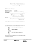
Example of local addressing
7KLVH[DPSOHDGGUHVVHVDELWLQDQ,2PRGXOHWKDWUHVLGHVLQWKH
ORFDO FKDVVLV
Tags for the input module:
Tags for the output module:
Local:1:I.Data.0
Local:1:I.Fault.0
Local:2:I.Data.0
Local:2:I.Fault.0
Local:2:O.Data.0
40049
7KHQDPH/RFDOLQGLFDWHVWKDWWKHVHWDJVUHIHUHQFHPRGXOHVWKDWDUHLQ
WKHVDPHFKDVVLVDVWKH FRQWUROOHU
1756-6.5.12 March 1999
3-18
Configuring I/O Modules
Example of remote addressing
7KLVH[DPSOHDGGUHVVHVDQ,2PRGXOHLQDUHPRWHFKDVVLV
SwitchesRack
(name assigned to the
1756-CNB module)
SensorRack
(name assigned to the
1756-CNB module)
40050
Tags for the output module:
SensorRack:1:I.Data.0
SensorRack:1:I.Fault.0
SensorRack:1:O.Data.0
1756-6.5.12 March 1999
Configuring I/O Modules
3-19
Defining aliases
$WDJDOLDVOHWV\RXFUHDWHRQHWDJWKDWUHSUHVHQWVDQRWKHUWDJ7KLVLV
XVHIXOIRUGHILQLQJVLPSOLILHGWDJQDPHVIRU,2YDOXHV)RU H[DPSOH
Example:
Description:
I/O structure
This example uses simpler tags to refer to
specific I/O points.
Local:0:O.Data.0
Local:0:I.Fault.0
alias
light_on = Local:0:O.Data.0
light_off = Local:0:I.Fault.0
Viewing Module Fault Information
(DFK,2PRGXOHSURYLGHVLQGLFDWLRQZKHQDIDXOWRFFXUV7KH
SURJUDPPLQJVRIWZDUHGLVSOD\VWKLVIDXOWLQIRUPDWLRQ
In this location:
The software displays:
Controller organizer
The I/O configuration portion displays the modules configured for the controller. If the
controller detects a fault with one of these modules, the controller organizer displays
a yellow attention symbol (/!\) over the device and over the I/O Configuration folder.
Connection tab from
module properties
If the module is inhibited, the controller organizer displays an attention symbol (/!\)
only over the device.
The module fault field displays the fault code returned to the controller (related to the
module) and the text detailing the fault.
Common categories for module errors are:
Connection request error
The controller is attempting to make a connection to
the module and has received an error. The
connection was not made.
Service request error
The controller is attempting to request a service from
the module and has received an error. The service
was not performed successfully.
Module configuration
rejected
The configuration in the module is invalid. This is
commonly caused by two unmatched owners.
Module key mismatch
Electronic keying is enabled and some part of the
keying information differs between the software and
the module.
1756-6.5.12 March 1999
3-20
Configuring I/O Modules
(DFK,2PRGXOHKDVVWDWXVELWVWKDWLQGLFDWHZKHQDIDXOWRFFXUV
<RXUORJLFVKRXOGPRQLWRUWKHVHVWDWXVELWV,IDQ\IDXOWVH[LVW\RXU
DSSOLFDWLRQVKRXOGWDNHDSSURSULDWHDFWLRQVXFKDVVKXWWLQJGRZQWKH
V\VWHPLQDFRQWUROOHGPDQQHU
<RXFDQFRQILJXUHPRGXOHVWRJHQHUDWHDPDMRUIDXOWLQWKHFRQWUROOHU
LIWKH\ORVHWKHLUFRQQHFWLRQZLWKWKHFRQWUROOHU
,I\RXGRQRWFRQILJXUHWKHPDMRUIDXOWWRRFFXU\RXVKRXOGPRQLWRU
WKHPRGXOHVWDWXV,IDPRGXOHIDXOWVRXWSXWVJRWRWKHLUFRQILJXUHG
IDXOWHGVWDWH7KHFRQWUROOHUDQGRWKHU,2PRGXOHVFRQWLQXHWR
RSHUDWHEDVHGRQROGGDWDIURPWKHIDXOWHGPRGXOH
1756-6.5.12 March 1999
$77(17,21 2XWSXWVUHVSRQGWRWKH³ODVW
QRQIDXOWHG´VWDWHRIWKHFRQWUROOLQJLQSXWV7RDYRLG
SRWHQWLDOLQMXU\DQGGDPDJHWRPDFKLQHU\PDNHVXUH
WKLVGRHVQRWFUHDWHXQVDIHRSHUDWLRQ&RQILJXUHFULWLFDO
,2PRGXOHVWRJHQHUDWHDFRQWUROOHUPDMRUIDXOWZKHQ
WKH\ORVHWKHLUFRQQHFWLRQVWRWKHFRQWUROOHU2UPRQLWRU
WKHVWDWXVRI,2PRGXOHV
Configuring I/O Modules
3-21
Using the programming software to view I/O faults
1. Select a module (“1756-IB16” in this example).
2. Click the right mouse button and select Properties.
)URPWKHSURJUDPPLQJVRIWZDUH\RXFDQPRQLWRUWKHVWDWXVRIDQ,2
PRGXOH7KHSURJUDPPLQJVRIWZDUHKDVDPRGXOHLQIRUPDWLRQWDE
WKDWGLVSOD\VPRGXOHIDXOWVWDWXVDQGRWKHULQIRUPDWLRQ<RXPXVWEH
RQOLQHWRJHWDFWXDOGDWD7KLVLQIRUPDWLRQLVUHDGIURPWKHDFWXDO
PRGXOHVRLW¶VRQO\DYDLODEOHLIWKHFRQQHFWLRQWRWKHPRGXOHLVRSHQ
<RXFDQDOVRUHVHWWKHPRGXOHIURPWKLVWDE
<RXFDQDOVRYLHZ,2LQIRUPDWLRQIURPWKHFRQQHFWLRQWDE7KLV
LQIRUPDWLRQLVUHDGIURPWKHFRQWUROOHU8VHWKLVWDELIWKHFRQQHFWLRQ
WRWKHPRGXOHLVVKXWGRZQ
1756-6.5.12 March 1999
3-22
Configuring I/O Modules
<RXFDQDOVRPRQLWRUWKHVWDWXVRIWKHPRGXOH,2WDJVLQWKHWDJ
PRQLWRU0RVWPRGXOHVKDYHVWDWXVELWVWRLQGLFDWHLIGDWDLVEHLQJ
XSGDWHGRULIWKHPRGXOHLVLQKLELWHG
Double-click on controller tags
Using logic to monitor I/O faults
<RXFDQDOVRXVHORJLFWRPRQLWRU,2IDXOWV
example 1
This example uses the MODULE object to determine whether any I/O module has lost its connection with the controller. If the controller I/O LED is
flashing green, LedStatus = 2. The EQU example determines whether the I/O LED is flashing green.
1756-6.5.12 March 1999
Configuring I/O Modules
3-23
example 2
This example uses the PROGRAM object to determine whether an I/O fault has occurred and was logged to the FAULTLOG. The fault_record structure
is of this user-defined data type:
Member:
Data Type:
Style:
Value:
Description:
TimeStampLow
DINT
Decimal
xxxxxxxx
time of fault (lower 32 bits)
TimeStampHigh
DINT
Decimal
xxxxxxxx
time of fault (upper 32 bits)
Type
INT
Decimal
0003
I/O fault
Code
INT
Decimal
0016
I/O connection fault
ModulePort
DINT
Decimal
00000001
port 1, backplane
ModuleInstance
DINT
Decimal
xxxxxxxx
module instance number
ErrorCode
DINT
Decimal
xxxxxxxx
depends on module
ErrorInfo
DINT
Decimal
xxxxxxxx
depends on module
spare1
DINT
Decimal;
00000000
unused
spare2
DINT
Decimal
00000000
unused
spare3
DINT
Decimal
00000000
unused
spare4
DINT
Decimal
00000000
unused
This would tell you the module that faulted. You can determine the ModuleInstance for a module by using a GSV: MODULE object name, module
name, INSTANCE attribute.
example 3
This example uses the MODULE object to get a specific fault code and fault information from a specified module. In this case, you would already
know which module to check.
)RUPRUHLQIRUPDWLRQRQHKDQGOLQJIDXOWVVHHFKDSWHU
)RUPRUHLQIRUPDWLRQRQXVLQJWKH*69LQVWUXFWLRQVHHWKH
/RJL[,QVWUXFWLRQ6HW5HIHUHQFH0DQXDOSXEOLFDWLRQ
1756-6.5.12 March 1999
3-24
Configuring I/O Modules
1RWHV
1756-6.5.12 March 1999
Chapter
4
Organizing Data
Using This Chapter
For information about:
See page:
How the controller stores data
Creating tags
Using base tags
Using structures
Viewing an array as a collection of elements
Viewing an array as a block of memory
Aliasing tags
Scoping tags
How the Controller Stores Data
4-1
4-2
4-6
4-9
4-13
4-15
4-19
4-20
7KH/RJL[FRQWUROOHUPHPRU\VWRUHVERWKGDWDDQGORJLF7KHUH
DUH.E\WHVRIPHPRU\LQWKHEDVHFRQWUROOHU
Base controller
(1756-L1)
160 Kbytes
processes I/O
processes produced/consumed tags
stores tags
stores program logic
7RLQFUHDVHPHPRU\FDSDFLW\\RXFDQDGGRQH0[PHPRU\
ERDUG<RXFDQLQVWDOOD
0.E\WHVPHPRU\H[SDQVLRQERDUGRU
00E\WHVPHPRU\H[SDQVLRQERDUGRU
00E\WHVPHPRU\H[SDQVLRQERDUG
1756-6.5.12 March 1999
4-2
Organizing Data
7KHPHPRU\H[SDQVLRQERDUGFKDQJHVKRZWKHFRQWUROOHUVWRUHVGDWD
DQGORJLF2QFHLQVWDOOHGWKH.E\WHVRIPHPRU\RIWKHEDVH
FRQWUROOHUDUHGHGLFDWHGWRKDQGOLQJ,2DQGSURGXFHGFRQVXPHGWDJV
7KHDGGHGPHPRU\LVGHGLFDWHGWRORJLFDQGWDJVWRUDJH
Controller with memory expansion board
(1756-L1Mx)
160 Kbytes
added
memory
Creating Tags
processes I/O
processes produced/consumed tags
stores tags
stores program logic
7KH/RJL[FRQWUROOHUXVHVWDJVIRUVWRULQJDQGDFFHVVLQJGDWD$
WDJLVVLPLODUWRDYDULDEOHDVXVHGE\SURJUDPPLQJODQJXDJHV$WDJ
KDVDQDPHWKDWGHVFULEHVWKHGDWDWKHWDJVWRUHVDQGDGDWDW\SHWKDW
LGHQWLILHVWKHVL]HDQGOD\RXWRIGDWDWKHWDJFDQVWRUH
7KHFRQWUROOHUVWRUHVWDJVDV\RXFUHDWHWKHPDQGDVWKH\ILWLQWRWKH
FRQWUROOHUPHPRU\7KHUHDUHQRSUHGHILQHGGDWDWDEOHVVXFKDVLQ
3/&FRQWUROOHUV7KH/RJL[FRQWUROOHUXVHVLWVPHPRU\PRUH
HIILFLHQWO\E\VWRULQJWDJVDVQHHGHGDQGZKHUHWKH\EHVWILWLQ
PHPRU\7DJVRIVLPLODUGDWDW\SHVDUHQRWQHFHVVDULO\JURXSHG
WRJHWKHULQPHPRU\,I\RXZDQWWRJURXSGDWDXVHDQDUUD\
7KHUHDUHWKUHHW\SHVRIWDJV
Tag Type:
Description:
base
A base tag is a tag that actually defines the memory
where a data element is stored.
An alias tag is a tag that references memory defined by
another tag. An alias tag can refer to a base tag or
another alias tag.
alias
consumed
1756-6.5.12 March 1999
Alias tags are useful for creating standardized programs
that can be duplicated without having to readdress
instructions. By using alias tags, each copy of the
program can reference different base tags.
A consumed tag is a tag whose data value comes from
another controller.
Organizing Data
4-3
Data types
:KHQ\RXGHYHORSDSURMHFWWKHFRQWUROOHUSURYLGHVDVHWRI
SUHGHILQHGGDWDW\SHV
predefined data types
7KHFRQWUROOHUGDWDW\SHVIROORZWKH,(&GHILQHGGDWDW\SHV
7KHSUHGHILQHGDWRPLFGDWDW\SHVDUH
Data type:
Description:
Range:
BOOL
1-bit boolean
SINT
INT
DINT
REAL
1-byte integer
2-byte integer
4-byte integer
4-byte floating-point number
0 = off
1 = on
-128 to 127
-32,768 to 32,767
-2,147,483,648 to 2,147,483,647
-3.402823E38 to -1.1754944E−38 (negative values)
and
0
and
1.1754944E−38 to 3.402823E38 (positive values)
7KH5($/GDWDW\SHDOVRVWRUHVLQILQLW\DQG1$1EXWWKHVRIWZDUH
GLVSOD\GLIIHUVEDVHGRQWKHGLVSOD\IRUPDW
Display Format:
Equivalent:
Real
+infinite
- infinite
+NAN
-NAN
+infinite
- infinite
+NAN
-NAN
Exponential
1.$
-1.$
1.#QNAN
-1.#QNAN
1.#INF000e+000
-1.#INF000e+000
1.#QNAN00e+000
-1.#QNAN00e+000
1756-6.5.12 March 1999
4-4
Organizing Data
7KHSUHGHILQHGVWUXFWXUHVDUH
Data type:
Description:
AXIS1
CONTROL
COUNTER
control structure for an axis
MESSAGE1
MOTION_GROUP1
MOTION_INSTRUCTION
PID
TIMER
1.
control structure for array (file) instructions
control structure for counter instructions
control structure for the MSG instruction
control structure for a motion group
control structure for motion instructions
control structure for the PID instruction
control structure for timer instructions
These structures do not support arrays, cannot be nested in user-defined structures, and
cannot be passed to other routines via a JSR instruction. These are controller-only tags.
Naming tags
7DJQDPHVIROORZ,(&LGHQWLILHUUXOHVDQG
PXVWEHJLQZLWKDQDOSKDEHWLFFKDUDFWHU$=RUD]RUDQ
XQGHUVFRUH B
FDQFRQWDLQRQO\DOSKDEHWLFFKDUDFWHUVQXPHULFFKDUDFWHUV
DQG XQGHUVFRUHV
FDQKDYHDVPDQ\DVFKDUDFWHUV
PXVWQRWKDYHFRQVHFXWLYHRUWUDLOLQJXQGHUVFRUHFKDUDFWHUVB
7DJQDPHVDUHQRWFDVHVHQVLWLYH
<RXFDQDOVRDGGGHVFULSWLRQVWRWDJV'HVFULSWLRQVFDQKDYHDVPDQ\
DVFKDUDFWHUV<RXFDQXVHDQ\SULQWDEOHFKDUDFWHU
Entering tags
<RXXVHWKHSURJUDPPLQJVRIWZDUHWRFUHDWHWDJV<RXFDQHLWKHU
FUHDWHDWDJLQGLYLGXDOO\RUWKURXJKWKH(GLW7DJVWDERIWKH
GDWD PRQLWRU
1756-6.5.12 March 1999
Organizing Data
4-5
:KLFKHYHUPHWKRG\RXFKRRVHWRFUHDWHDWDJ\RXGHILQH
In this field:
Enter:
Name
Description
Tag Type
Enter the name of the tag.
Enter the description of the tag (optional).
Select one of these:
Data Type
Scope
Display Style
Produce this tag
Base
normal tag
Alias
tag that references another tag or part of another tag
Consumed
tag whose value is produced by another controller
Select the data type. The programming software displays a list of the available data
types. The list consists of the predefined data types and any user-defined
data types.
If the tag is to be an array, specify the number of elements in each dimension. There
can be as many as 3 dimensions. If the tag is not an array, or you do not want all 3
dimensions, set the dimension fields to zero (0).
Select the scope in which to create the tag. You can select controller scope or one of
the existing program scopes.
Select the display style of the tag. The programming software displays a list of the
available styles, which depends on the data type. The style you select becomes the
default display type when monitoring that tag with the programming software.
Select whether to make this tag available to other controllers. Specify how many
controllers can consume the tag.
7RFUHDWHDWDJLQGLYLGXDOO\
Select File → New Component → Tag.
Define the tag.
1756-6.5.12 March 1999
4-6
Organizing Data
7RFUHDWHDWDJIURPWKH(GLW7DJVWDERIWKHGDWDPRQLWRU
1. Select controller tags or
program tags.
2. Select Edit Tags.
3. Define the tag.
<RXFDQFUHDWHWDJVEHIRUHHQWHULQJSURJUDPORJLFRU\RXFDQHQWHU
WDJQDPHVDV\RXHQWHUORJLFDQGGHILQHWKHWDJVODWHUXVLQJWKH1HZ
7DJGLDORJER[
1. Select the tag name in tag editor.
2. Right-click on the tag name.
4. Define the tag.
Using Base Tags
$EDVHWDJVWRUHVRQHYDOXHDWDWLPH7KHW\SHRIYDOXHGHSHQGVRQ
WKHGDWDW\SH8VHWKHVHDWRPLFGDWDW\SHVWRGHILQHEDVH WDJV
%22/
6,17
,17
',17
5($/
Memory allocation for base tags
7KHDPRXQWRIPHPRU\WKDWDWDJXVHVGHSHQGVRQWKHGDWDW\SH7KH
PLQLPXPDOORFDWLRQZLWKLQWKHFRQWUROOHULVIRXUE\WHV
6RPHRIWKHGDWDW\SHVDUHVPDOOHUWKDQIRXUE\WHV%22/6,17DQG
,17:KHQ\RXFUHDWHDWDJXVLQJRQHRIWKHVHGDWDW\SHVWKH
FRQWUROOHUDOORFDWHVIRXUE\WHVEXWWKHGDWDRQO\ILOOVWKHSDUWLWQHHGV
7RXVHPHPRU\PRUHHIILFLHQWO\FUHDWHDUUD\VRUVWUXFWXUHVWRKROG
WKHVHVPDOOHUGDWDW\SHV6HHWKHIROORZLQJH[DPSOHV
1756-6.5.12 March 1999
Organizing Data
4-7
0RVWLQVWUXFWLRQVGRQRWRSHUDWHRQ%22/DUUD\V)RU%22/GDWDLW
PLJKWEHPRUHHIILFLHQWWRFUHDWHDVWUXFWXUHLQVWHDGRIDQDUUD\
7KHIROORZLQJH[DPSOHVVKRZPHPRU\DOORFDWLRQIRUEDVHWDJVXVLQJ
WKHDWRPLFGDWDW\SHV
bool_value as BOOL
7KLVH[DPSOHXVHVRQHELWRIWKHGDWDDOORFDWLRQ
Bit
31
allocation
not used
small_value as SINT
1
bool_value
7KLVH[DPSOHXVHVELWVRIWKHGDWDDOORFDWLRQ
Bit:
31
allocation
not used
value as INT
7KLVH[DPSOHXVHVELWVRIWKHGDWDDOORFDWLRQ
Bit:
31
allocation
not used
big_value as DINT
8
7
0
small_value
16
15
0
value
7KLVH[DPSOHXVHVDOOELWVRIWKHGDWDDOORFDWLRQ
Bit:
31
allocation
big_value
float_value as REAL
0
0
7KLVH[DPSOHXVHVDOOELWVRIWKHGDWDDOORFDWLRQ
Bit:
31
allocation
float_value
0
1756-6.5.12 March 1999
4-8
Organizing Data
Data type conversions
,I\RXPL[GDWDW\SHVIRUSDUDPHWHUVZLWKLQDQLQVWUXFWLRQVRPH
LQVWUXFWLRQVDXWRPDWLFDOO\FRQYHUWGDWDWRDQRSWLPDOGDWDW\SHIRU
WKDWLQVWUXFWLRQ,QVRPHFDVHVWKHFRQWUROOHUFRQYHUWVGDWDWRILWD
QHZGDWDW\SHLQVRPHFDVHVWKHFRQWUROOHUMXVWILWVWKHGDWDDVEHVW
LW FDQ
Conversion:
Result:
large integer to small integer
The controller truncates the upper portion of the larger integer and
generates an overflow.
For example:
Decimal Binary
DINT 65,665 0000_0000_0000_0001_0000_0000_1000_0001
INT
129
0000_0000_1000_0001
SINT
-127
1000_0001
No data precision is lost
Data precision could be lost. Both data types store data in 32 bits, but the
REAL type uses some of its 32 bits to store the exponent value. If precision
is lost, the controller takes it from the least-significant portion of the DINT.
The controller rounds the fractional part and truncates the upper portion of
the non-fractional part. If data is lost, the controller sets the overflow
status flag.
SINT or INT to REAL
DINT to REAL
REAL to SINT, INT, or DINT
Rounding is to the nearest even number:
less than .5
round down
equal to .5
round to nearest even integer
greater than .5 round up
For example:
REAL (source)
2.5
-2.5
1.6
-1.6
1.5
-1.5
1.4
-1.4
DINT (result)
2
-2
2
-2
2
-2
1
-1
7KHFRQWUROOHUFDQQRWFRQYHUWGDWDWRRUIURPWKH%22/GDWDW\SH
Specifying bits
,QDGGLWLRQWRXVLQJ%22/W\SHWDJVWRVSHFLI\DELW\RXFDQXVHELW
VSHFLILHUVZLWKLQLQWHJHUW\SHWDJV6,17,17DQG',177KHELW
VSHFLILHULGHQWLILHVDELWZLWKLQWKHWDJ7KHELWVSHFLILHUUDQJH
GHSHQGVRQWKHGDWDW\SH
1756-6.5.12 March 1999
Data Type:
Bit Specifier Range:
SINT
INT
DINT
0-7
0-15
0-31
Organizing Data
4-9
7RVSHFLI\DELWZLWKLQDQLQWHJHUVSHFLI\
[>\@
ZKHUH
This
Is:
x
.
[]
integer tag name
specifies that a bit reference follows
encloses a bit reference
only needed for a non-numeric bit reference
bit reference
y
7KHELWUHIHUHQFHFDQEHDQLPPHGLDWHQXPEHUDWDJRUDQ
H[SUHVVLRQ<RXFDQXVHWKHVHRSHUDWRUVWRVSHFLI\DELW
Operator:
+
*
/
AND
FRD
NOT
OR
TOD
SQR
XOR
Description:
add
subtract/negate
multiply
divide
AND
BCD to integer
complement
OR
integer to BCD
square root
exclusive OR
)RUH[DPSOH
Example:
Description:
value.5
value.[5]
Both of these examples reference the 6th bit in
the integer value. When you use an immediate
number you do not need the brackets.
This example references the bit identified by
another_value within the integer value.
This example references a bit identified by
control.pos within the integer value.
This example uses an expression to identify a
bit within the integer value.
value.[another_value]
value.[control.pos]
value.[control.pos - number + 5]
Using Structures
$VWUXFWXUHVWRUHVDJURXSRIGDWD(DFKPHPEHURIWKHVWUXFWXUHFDQ
EHDGLIIHUHQWGDWDW\SH7KHFRQWUROOHUKDVLWVRZQSUHGHILQHG
VWUXFWXUHV(DFK,2PRGXOHKDVLWVRZQSUHGHILQHGVWUXFWXUHV
<RX FDQDOVRFUHDWHVSHFLDOL]HGXVHUGHILQHGVWUXFWXUHVXVLQJDQ\
FRPELQDWLRQRISUHGHILQHGDWRPLFGDWDW\SHVDQGPRVW
RWKHU VWUXFWXUHV
)RULQIRUPDWLRQDERXWFRS\LQJGDWDWRDVWUXFWXUHVHHWKH&23
LQVWUXFWLRQLQWKH/RJL[&RQWUROOHU,QVWUXFWLRQ6HW5HIHUHQFH
0DQXDOSXEOLFDWLRQ
1756-6.5.12 March 1999
4-10
Organizing Data
Predefined structures
7KHFRQWUROOHUVXSSRUWVWKHVHSUHGHILQHGVWUXFWXUHVHDFKRIZKLFK
VWRUHVUHODWHGLQIRUPDWLRQIRUVSHFLILFLQVWUXFWLRQV
$;,6
&21752/
&2817(5
0(66$*(
027,21B*5283
027,21B,16758&7,21
3,'
7,0(5
1.
These structures do not support arrays and cannot be nested in user-defined structures.
)RUPRUHLQIRUPDWLRQDERXWWKHLQVWUXFWLRQVWKDWXVHWKHVHVWUXFWXUHV
VHHWKH/RJL[&RQWUROOHU,QVWUXFWLRQ6HW5HIHUHQFH0DQXDO
SXEOLFDWLRQ
Module-defined structure
7KH/RJL[FRQWUROOHUDXWRPDWLFDOO\FUHDWHVWKH,2VWUXFWXUHV
QHHGHGIRUHDFK,2PRGXOH\RXFRQILJXUHIRUWKHV\VWHPVHHWKH
SUHYLRXVFKDSWHU7KHVHVWUXFWXUHVXVXDOO\FRQWDLQPHPEHUVIRUGDWD
VWDWXVLQIRUPDWLRQDQGIDXOWLQIRUPDWLRQ
1. Select Data Types.
2. Click the right mouse button and select
New Data Type.
User-defined structure
$XVHUGHILQHGVWUXFWXUHJURXSVGLIIHUHQWW\SHVRIGDWDLQWRDVLQJOH
QDPHGHQWLW\$XVHUGHILQHGVWUXFWXUHFRQWDLQVRQHRUPRUHGDWD
GHILQLWLRQVFDOOHGPHPEHUV&UHDWLQJDPHPEHULQDXVHUGHILQHG
VWUXFWXUHLVMXVWOLNHFUHDWLQJDQLQGLYLGXDOWDJ7KHGDWDW\SHIRUHDFK
PHPEHUGHWHUPLQHVWKHDPRXQWRIPHPRU\DOORFDWHGIRUWKHPHPEHU
7KHGDWDW\SHIRUHDFKPHPEHUFDQEHDDQ
1756-6.5.12 March 1999
DWRPLFGDWDW\SH
SUHGHILQHGVWUXFWXUH
XVHUGHILQHGVWUXFWXUH
VLQJOHGLPHQVLRQDUUD\RIDQDWRPLFGDWDW\SH
VLQJOHGLPHQVLRQDUUD\RIDSUHGHILQHGVWUXFWXUH
VLQJOHGLPHQVLRQDUUD\RIDXVHUGHILQHGVWUXFWXUH
Organizing Data
4-11
8VHWKHSURJUDPPLQJVRIWZDUHWRFUHDWH\RXURZQVWUXFWXUHV
For:
In this field:
Enter:
user-defined structure
Name
Description
Name
Data Type
Enter the name of the structure.
Enter the description of the structure (optional).
Enter the name of the member.
Select the data type. The programming software displays a list of the
available data types. The list consists of the predefined data types
and any user-defined data types.
Select the display style of the member. The programming software
displays a list of the available styles, which depends on the data type.
Enter the description of the member (optional).
each member of the
structure
Style
Description
<RXFDQFUHDWHHGLWDQGGHOHWHXVHUGHILQHGVWUXFWXUHVRQO\ZKHQ
SURJUDPPLQJRIIOLQH
,I\RXPRGLI\DXVHUGHILQHGVWUXFWXUHDQGFKDQJHLWVVL]HWKH
H[LVWLQJYDOXHVRIDQ\WDJVWKDWXVHWKHVWUXFWXUHDUHVHWWR]HUR
Memory allocation for user-defined structures
7KHPHPRU\DOORFDWHGIRUDXVHUGHILQHGVWUXFWXUHGHSHQGVRQWKH
GDWDW\SHVIRUHDFKPHPEHUZLWKLQWKHVWUXFWXUH(DFKPHPEHULV
DOORFDWHGPHPRU\WRVWDUWRQDQDSSURSULDWHE\WH,17RU',17
ERXQGDU\7KLVLVGLIIHUHQWWKDQWDJVZKLFKDUHDOZD\VDOORFDWHGDV
',17<RXFDQRSWLPL]HPHPRU\E\FRPELQLQJGDWDDVPHPEHUV
ZLWKLQD VWUXFWXUH
)RUH[DPSOH
User-Defined
Structure Name:
Load_Info
Location
Member:
Data Type:
Style:
Description:
Height
Width
Weight
W_Flag
L_Flag
Source
Destination
Info
SINT
SINT
REAL
BOOL
BOOL
INT
INT
Load_Info
Decimal
Decimal
Float
Decimal
Decimal
Decimal
Decimal
none
load Height in feet
load Width in feet
load Weight in pounds
set true if load is stretch wrapped
set true if load is labeled
system source location
system destination location
load information structure
1756-6.5.12 March 1999
4-12
Organizing Data
0HPRU\LVDOORFDWHGLQWKHRUGHURIWKHPHPEHUV
Bit:
data allocation 1
data allocation 2
data allocation 3
data allocation 4
31
24
unused
Destination
unused
unused
23
unused
16
15
8
7
0
Source
Width
Weight
unused
Height
bit 0 W_Flag
bit 1 L_Flag
Referencing members within a structure
<RXUHIHUHQFHPHPEHUVLQDVWUXFWXUHE\XVLQJWKHWDJQDPHDQGWKHQ
WKHPHPEHUQDPHWDJBQDPHPHPEHUBQDPH
)RUH[DPSOH
Example:
Description:
timer_1.pre
This example references the .PRE value of
the timer_1 structure.
This examples references the Height
member of the user-defined input_load
structure
input_load as data type load_info
input_load.height
,IWKHVWUXFWXUHLVHPEHGGHGLQDQRWKHUVWUXFWXUHXVHWKHWDJQDPHRI
WKHVWUXFWXUHDWWKHKLJKHVWOHYHOIROORZHGE\DVXEVWUXFWXUHWDJQDPH
DQGPHPEHUQDPHWDJBQDPHVXEVWUXFWXUHBQDPHPHPEHUBQDPH
)RUH[DPSOH
Example:
Description:
input_location as data type location
This example references the height member
of the load_info structure in the
input_location structure.
input_location.load_info.height
,IWKHVWUXFWXUHGHILQHVDQDUUD\XVHWKHDUUD\WDJIROORZHGE\WKH
SRVLWLRQLQWKHDUUD\DQGDQ\VXEVWUXFWXUHDQGPHPEHUQDPHV
DUUD\BWDJ>SRVLWLRQ@PHPEHU
RU
DUUD\BWDJ>SRVLWLRQ@VXEVWUXFWXUHBQDPHPHPEHUBQDPH
)RUH[DPSOH
Example:
Description:
conveyor as array location[100]
This specifies a 100 word array. Each
element in the array is data type location (a
structure).
This example references the source member
of the 11th element in the array (array
elements are zero based).
This example references the height member
of the info structure in the 11th element of
the array (array elements are zero based).
conveyor[10].source
conveyor[10].info.height
1756-6.5.12 March 1999
Organizing Data
Viewing an Array as a Collection
of Elements
4-13
$UUD\VOHW\RXJURXSDVHWRIGDWDRIWKHVDPHGDWDW\SHE\WKHVDPH
QDPHDQGWRXVHVXEVFULSWVWRLGHQWLI\LQGLYLGXDO HOHPHQWV$Q
HOHPHQWLQDQDUUD\FDQEHDQDWRPLFGDWDW\SHRUDVWUXFWXUH
<RXVSHFLI\DQHOHPHQWLQDQDUUD\E\LWVVXEVFULSWV(QWHUWKHDUUD\
WDJQDPHIROORZHGE\WKHVXEVFULSWVLQVTXDUHEUDFNHWV7KH
VXEVFULSWVPXVWVSHFLI\DYDOXHIRUHDFKGLPHQVLRQRIWKHDUUD\
'LPHQVLRQVDUH]HUREDVHG
For this array:
Specify:
one dimension
array_name[subscript_0]
two dimension
array_name[subscript_0, subscript_1]
three dimension
array_name[subscript_0, subscript_1, subscript_2]
$QDUUD\FDQKDYHDVPDQ\DVWKUHHGLPHQVLRQV7KHWRWDOQXPEHURI
HOHPHQWVLQDQDUUD\LVWKHSURGXFWRIHDFKGLPHQVLRQ¶VVL]H
This array:
one dimension
Stores data like:
For example:
Tag name:
Type
one_d_array
DINT[7]
Dimension 0
Dimension 1
Dimension 2
7
--
--
Dimension 0
Dimension 1
Dimension 2
4
5
--
total number of elements = 7
valid subscript range DINT[x] where x=0–6
two dimension
Tag name:
Type
two_d_array
DINT[4,5]
total number of elements = 4 ∗ 5 = 20
valid subscript range DINT[x,y] where x=0–3; y=0–4
three dimension
Tag name:
Type
Dimension 0
three_d_array
DINT[2,3,4]
2
Dimension 1
Dimension 2
3
4
total number of elements = 2 ∗ 3 ∗ 4 = 24
valid subscript range DINT[x,y,z] where x=0–1; y=0–2, z=0–3
1756-6.5.12 March 1999
4-14
Organizing Data
Indexing through arrays
7RG\QDPLFDOO\FKDQJHWKHDUUD\HOHPHQWWKDW\RXUORJLFUHIHUHQFHV
XVHWDJRUH[SUHVVLRQDVWKHVXEVFULSWWRSRLQWWRWKHHOHPHQW7KLVLV
VLPLODUWRLQGLUHFWDGGUHVVLQJLQ3/&ORJLF<RXFDQXVHWKHVH
RSHUDWRUVLQDQH[SUHVVLRQWRVSHFLI\DQDUUD\VXEVFULSW
Operator:
+
*
/
AND
FRD
NOT
OR
TOD
SQR
XOR
Description:
add
subtract/negate
multiply
divide
AND
BCD to integer
complement
OR
integer to BCD
square root
exclusive OR
)RUH[DPSOH
Definitions:
Example:
Description:
This example references element 5 in the array.
The reference is static because the subscript
value remains constant.
This example references element 5 in the array.
The reference is dynamic because the logic can
change the subscript by changing the value
of position.
This example references element 7 (2+5) in the
array. The reference is dynamic because the
logic can change the subscript by changing the
value of position or offset.
my_list
defined as DINT[10]
my_list[5]
my_list
defined as DINT[10]
MOV the value 5 into position
position
defined as DINT
my_list[position]
my_list
defined as DINT[10]
position
defined as DINT
MOV the value 2 into position
MOV the value 5 into offset
offset
defined as DINT
my_list[position+offset]
0DNHVXUHDQ\DUUD\VXEVFULSW\RXHQWHULVZLWKLQWKHERXQGDULHVRI
WKHVSHFLILHGDUUD\,QVWUXFWLRQVWKDWYLHZDUUD\VDVDFROOHFWLRQRI
HOHPHQWVJHQHUDWHDPDMRUIDXOWW\SHFRGHLIDVXEVFULSW
H[FHHGVLWVFRUUHVSRQGLQJGLPHQVLRQ
1756-6.5.12 March 1999
Organizing Data
4-15
Specifying Bits Within Arrays
<RXFDQDGGUHVVELWVZLWKLQHOHPHQWVRIDUUD\V)RUH[DPSOH
Definitions:
Example:
Description:
This example references the bit 2 in element 1
of the array.
This example references the bit 15 of the
element array2[3,4].
array1
defined as DINT[5]
array1[1].2
array2
defined as INT[17,36]
array2[3,4].15
array3
1st dimension has 17 elements
2nd dimension has 36 elements
defined as SINT[2,4,6]
array3[1,3,2].4
MyArray
1st dimension holds 2 elements
2nd dimension holds 4 elements
3rd dimension holds 6 elements
defined as SINT[100]
This example references bit 4 of the element
array3[1,3,2].
MyIndex
MyArray
defined as SINT
defined as INT[100]
MyArray[(MyIndex AND NOT 7) /
8].[MyIndex AND 7]
This example references a bit within an
SINT array.
MyIndex
MyArray
defined as INT
defined as DINT[100]
MyArray[(MyIndex AND NOT 15) /
16].[MyIndex AND 15]
This example references a bit within an
INT array.
MyIndex
defined as DINT
MyArray[(MyIndex AND NOT 31) /
32].[MyIndex AND 31]
This example references a bit within an
DINT array.
<RXFDQDOVRXVHWKHRSHUDWRUVVKRZQLQWKHWDEOHRQSDJHWR
VSHFLI\ELWV
Viewing an Array as a Block
of Memory
7KHGDWDLQDQDUUD\LVVWRUHGFRQWLJXRXVO\LQPHPRU\7KHILOH
DUUD\LQVWUXFWLRQVW\SLFDOO\UHTXLUHDVWDUWLQJDGGUHVVZLWKLQDQDUUD\
DQGDOHQJWKZKLFKGHWHUPLQHVZKLFKHOHPHQWVDQGKRZPDQ\
HOHPHQWVWKHLQVWUXFWLRQUHDGVRUZULWHV
7KHVHLQVWUXFWLRQVPDQLSXODWHDUUD\GDWDDVDFRQWLJXRXVEORFN
RI PHPRU\WKHUHPDLQLQJLQVWUXFWLRQVPDQLSXODWHDUUD\GDWDDV
LQGLYLGXDOHOHPHQWV
BSL
FLL
BSR
LFL
COP
LFU
DDT
SQI
FBC
SQL
FFL
SQO
FFU
,PSRUWDQW,IDQLQVWUXFWLRQDWWHPSWVWRUHDGGDWDEH\RQGWKHHQGRI
DQDUUD\WKHLQVWUXFWLRQUHDGVZKDWHYHUGDWDKDSSHQVWR
EHWKHUHDQGSURFHVVHVLWDVLILWZHUHYDOLGGDWDQRHUURU
RFFXUV,IDQLQVWUXFWLRQDWWHPSWVWRZULWHGDWDEH\RQG
WKHHQGRIDQDUUD\DPDMRUIDXOWRFFXUVW\SH
FRGH 1756-6.5.12 March 1999
4-16
Organizing Data
How the controller stores array data
7KHIROORZLQJWDEOHVKRZVWKHVHTXHQWLDORUGHURIWKHHOHPHQWVLQWKH
H[DPSOHVRQSDJH
One-Dimensional Array Elements
(ascending order):
Two-Dimensional Array Elements
(ascending order):
Three-Dimensional Array Elements
(ascending order):
one_d_array[0]
one_d_array[1]
one_d_array[2]
one_d_array[3]
one_d_array[4]
one_d_array[5]
one_d_array[6]
two_d_array[0,0]
two_d_array[0,1]
two_d_array[0,2]
two_d_array[0,3]
two_d_array[0,4]
two_d_array[1,0]
two_d_array[1,1]
two_d_array[1,2]
two_d_array[1,3]
two_d_array[1,4]
two_d_array[2,0]
two_d_array[2,1]
two_d_array[2,2]
two_d_array[2,3]
two_d_array[2,4]
two_d_array[3,0]
two_d_array[3,1]
two_d_array[3,2]
two_d_array[3,3]
two_d_array[3,4]
three_d_array[0,0,0]
three_d_array[0,0,1]
three_d_array[0,0,2]
three_d_array[0,0,3]
three_d_array[0,1,0]
three_d_array[0,1,1]
three_d_array[0,1,2]
three_d_array[0,1,3]
three_d_array[0,2,0]
three_d_array[0,2,1]
three_d_array[0,2,2]
three_d_array[0,2,3]
three_d_array[1,0,0]
three_d_array[1,0,2]
three_d_array[1,0,3]
three_d_array[1,1,0]
three_d_array[1,1,1]
three_d_array[1,1,2]
three_d_array[1,1,3]
three_d_array[1,2,0]
three_d_array[1,2,1]
three_d_array[1,2,2]
three_d_array[1,2,3]
For an array with only one dimension,
tag_name[subscript_0], subscript_0
increments to its maximum value.
For an array with two dimensions,
tag_name[subscript_0,subscript_1],
subscript_0 is held fixed at 0 while
subscript_1 increments from 0 to its maximum
value. Subscript_0 then increments by 1 (if
dimension 0 is greater than 1) and is held fixed
while subscript_1 increments through its
range again. This pattern continues until both
subscripts reach their maximum values.
1756-6.5.12 March 1999
For an array with three dimensions,
tag_name[subscript_0, subscript_1,
subscript_2], subscript_0 is held fixed at 0
while subscript_1 and subscript_2 increment
just like a two- dimensional array. Subscript_0
then increments by 1 (if dimension 0 is greater
than 1) and is held fixed until subscript_1 and
subscript_2 reach their maximum values. This
pattern continues until all three subscripts
reach their maximum values.
Organizing Data
4-17
Varying a dimension
7KH$9(657DQG67'LQVWUXFWLRQVKDYHD'LPHQVLRQWRYDU\
RSHUDQG7KHLQVWUXFWLRQXVHVWKLVRSHUDQGWRFDOFXODWHDQRIIVHWWKDW
WKHLQVWUXFWLRQXVHVWRGHWHUPLQHZKLFKHOHPHQWVRIWKH$UUD\WRUHDG
RUZULWH
Array:
Dimension to
Offset:
vary:
one dimension
0
1
two dimension
0
dimension_1
1
1
0
(dimension_1) ∗ (dimension_2)
1
dimension_2
2
1
three dimension
Memory Allocation for Arrays
7KHDPRXQWRIPHPRU\WKDWDQDUUD\XVHVGHSHQGVRQWKHGDWDW\SH
XVHGWRFUHDWHWKHDUUD\7KHPLQLPXPDOORFDWLRQZLWKLQWKH
FRQWUROOHULVIRXUE\WHVZKLFKLVWKHVDPHDV%22/V6,17V
,17VRU ',17
7KHIROORZLQJH[DPSOHVVKRZPHPRU\DOORFDWLRQIRUYDULRXVDUUD\V
bit_values as BOOL[32]
7KLVH[DPSOHLVDQDUUD\ZLWKELWHOHPHQWVHDFKRIGDWDW\SH
%22/ ELWSHUHOHPHQW
Bit:
31
data allocation 1
[31] [30] [29] [28] [27] [26] [25] [24] [23] [22] [21] [20] [19] [18] [17] [16]
Bit:
15
data allocation 1
continued
[15] [14] [13] [12] [11] [10] [9]
small_values as SINT[8]
30
14
29
28
13
12
11
26
10
25
24
9
23
22
21
20
19
18
17
16
8
7
6
5
4
3
2
1
0
[8]
[7]
[6]
[5]
[4]
[3]
[2]
[1]
[0]
7KLVH[DPSOHLVDQDUUD\ZLWKHOHPHQWVHDFKRIGDWDW\SH6,17
E\WHSHUHOHPHQW
Bit:
31
data allocation 1
data allocation 2
small_values[3]
small_values[7]
small_values as SINT[3]
27
24
23
16
small_values[2]
small_values[6]
15
8
small_values[1]
small_values[5]
7
0
small_values[0]
small_values[4]
7KLVH[DPSOHLVDQDUUD\ZLWKHOHPHQWVHDFKRIGDWDW\SH6,17
E\WHSHUHOHPHQW%HFDXVHWKHPLQLPXPGDWDDOORFDWLRQLV
E\WHVWKHODVWE\WHLV]HUR
Bit:
31
data allocation 1
0
24
23
16
small_values[2]
15
8
small_values[1]
7
0
small_values[0]
1756-6.5.12 March 1999
4-18
Organizing Data
values as INT[4]
7KLVH[DPSOHLVDQDUUD\ZLWKHOHPHQWVHDFKRIGDWDW\SH,17
E\WHVSHUHOHPHQW
Bit:
31
data allocation 1
data allocation 2
values[1]
values[3]
big_values as DINT[2]
31
data allocation 1
data allocation 2
big_values[0]
big_values[1]
0
values[0]
values[2]
0
7KLVH[DPSOHLVDQDUUD\ZLWKHOHPHQWVHDFKHOHPHQWLVD
7,0(5 VWUXFWXUHE\WHVSHUVWUXFWXUH
Bit:
31
data allocation 1
data allocation 2
data allocation 3
data allocation 4
data allocation 5
data allocation 6
timer_list[0] status bits
timer_list[0].pre
timer_list[0].acc
timer_list[1] status bits
timer_list[1].pre
timer_list[1].acc
small_values as SINT[2,2,2]
15
7KLVH[DPSOHLVDQDUUD\ZLWKHOHPHQWVHDFKRIW\SH',17
E\WHV SHUHOHPHQW
Bit:
timer_list as TIMER[2]
16
0
7KLVH[DPSOHLVDWKUHHGLPHQVLRQDODUUD\ZLWKHOHPHQWVHDFKRI
GDWDW\SH6,17
Bit:
31
data allocation 1
data allocation 2
small_values[0,1,1] small_values[0,1,0] small_values[0,0,1] small_values[0,0,0]
small_values[1,1,1] small_values[1,1,0] small_values[1,0,1] small_values[1,0,0]
big_values as DINT[2,2,2]
24
23
16
15
8
7
0
7KLVH[DPSOHLVDWKUHHGLPHQVLRQDODUUD\ZLWKHOHPHQWVHDFKRI
W\SH',17
Bit:
31
data allocation 1
data allocation 2
data allocation 3
data allocation 4
data allocation 5
data allocation 6
data allocation 7
data allocation 8
big_values[0,0,0]
big_values[0,0,1]
big_values[0,1,0]
big_values[0,1,1]
big_values[1,0,0]
big_values[1,0,1]
big_values[1,1,0]
big_values[1,1,1]
0
<RXFDQPRGLI\DUUD\GLPHQVLRQVZKHQSURJUDPPLQJRIIOLQHZLWKRXW
ORVVRIWDJGDWD<RXFDQQRWPRGLI\DUUD\GLPHQVLRQVZKHQ
SURJUDPPLQJRQOLQH
1756-6.5.12 March 1999
Organizing Data
Aliasing Tags
Definitions:
$WDJDOLDVOHWV\RXFUHDWHRQHWDJWKDWUHSUHVHQWVDQRWKHUWDJ7KLVLV
XVHIXOIRUGHILQLQJVLPSOLILHGWDJQDPHVIRUHOHPHQWVRIVWUXFWXUHVRU
DUUD\V)RUH[DPSOH
Alias Example:
mylist[10]
array of 10 DINT elements
cookies[5]
array of 5 recipe elements
data type recipe flour as data type REAL
sugar as data type REAL
timer as array timer[5]
I/O structures
input point
local:0:I.Data.0
output point
local:1:O.Data.0
4-19
Description:
half = my_list[5]
This example uses the tag half as an alias to
my_list[5].
oatmeal =cookies[1]
This example uses tags referring to oatmeal as
oatmeal_flour = cookies[1].flour
aliases for different elements of the structure in
oatmeal_preset = cookies[1].timer[2].pre the first element of array cookies.
light_1 = local:0:I.Data.0
motor_1 = local:1:O.Data.0
This example uses simpler tags to refer to
specific I/O points.
<RXFDQXVHWKH7DJ(GLWRUWRFUHDWHDQDOLDVRU\RXFDQHQWHUWKHDOLDV
WDJDV\RXHQWHUORJLFDQGGHILQHWKHDOLDVODWHUXVLQJWKH1HZ7DJ
GLDORJER[
1. Select the tag name in tag editor.
2. Right-click on the tag name.
3. Define the tag.
4. Click Alias.
1756-6.5.12 March 1999
4-20
Organizing Data
7RFUHDWHDQDOLDVXVLQJWKH1HZ7DJGLDORJER[\RXGHILQHWKHWDJ
DQGVHOHFWWKHDOLDVWDJW\SH
In this field:
Enter:
Name
Description
Tag Type
Enter the name of the tag. This is the alias name.
Enter the description of the tag (optional).
Select:
Refers To
Data Type
Scope
Display Style
Produce this tag
Alias
tag that references another tag with the same characteristics
Enter the name of the tag that you are representing by the alias name. The
programming software displays a list of the available tags you can reference.
This field is automatically selected. Displays the data type of the resulting alias tag.
This is based on the tag you select for the Refers To field (described above).
You cannot specify array dimensions for an alias tag.
This field is automatically selected. Select the scope in which to create the tag. You
can select controller scope or one of the existing programs.
This field is automatically selected. Select the display style of the tag. The
programming software displays a list of the available styles, which depends on the
data type.
Select whether to make this tag available to other controllers through
controller-to-controller messaging. Specify how many controllers can consume
the tag.
The tag must be a controller-scoped tag. You can only choose to produce a tag when
programming offline.
<RXFDQJURXSVFRSHWDJVZLWKLQDQLQGLYLGXDOSURJUDPRUPDNH
WKHPDYDLODEOHWRLQVWUXFWLRQVDQ\ZKHUHLQWKHFRQWUROOHU:KHQ\RX
GHILQHWDJV\RXVSHFLI\WKHPDVHLWKHUSURJUDPWDJVORFDORU
FRQWUROOHUWDJVJOREDO
Scoping Tags
<RXFDQKDYHPXOWLSOHWDJVZLWKWKHVDPHQDPHDVORQJDVHDFKWDJ
KDVDGLIIHUHQWVFRSHRQHDVDFRQWUROOHUWDJDQGWKHRWKHUVDV
SURJUDPWDJVRUDOODVSURJUDPWDJV&HUWDLQOLPLWDWLRQVDSSO\WR
GDWDLQERWKVFRSHV
Action:
Controller Scope Tags
referencing the tag
naming a tag
any routine
routines within the same program
within the current program, a controller
defaults to the program scope tag
scope tag is not available if a program scope
tag of the same name exists
Program Scope Tags
messaging
you cannot reference both a controller scope
tag and a program scope tag with the same
name in a routine
no limitation
tag cannot be program scope
producer/consumer
tag must be controller scope
no limitation
tag must be controller scope
1756-6.5.12 March 1999
tag cannot be program scope
Organizing Data
4-21
Scoping tags local to a program
3URJUDPWDJVFRQVLVWRIGDWDWKDWLVXVHGH[FOXVLYHO\E\WKHURXWLQHV
ZLWKLQDSURJUDP7KHVHWDJVDUHORFDOWRDSURJUDP7KHURXWLQHVLQ
RWKHUSURJUDPVFDQQRWDFFHVVWKHSURJUDPWDJVRIDQRWKHUSURJUDP
Tag scope:
Description:
program
Program tags are data that is used exclusively by the routines
within a program. Other programs cannot access this data.
program data
Scoping tags global to a controller
&RQWUROOHUWDJVFRQVLVWRIGDWDWKDWLVDYDLODEOHWRDOOWKHURXWLQHV
ZLWKLQDFRQWUROOHUUHJDUGOHVVRIZKDWWDVNVRUSURJUDPVFRQWDLQWKH
URXWLQHV7KHVHWDJVDUHJOREDOWRWKHFRQWUROOHU
Tag scope:
Description:
controller
Controller tags are data that is available to all the tasks,
programs, and routines within a controller project.
controller tags
$OO,2WDJVDUHFUHDWHGDVFRQWUROOHUVFRSHGWDJVZKHQ\RXFUHDWHWKH
PRGXOHIRUWKHFRQWUROOHU
1756-6.5.12 March 1999
4-22
Organizing Data
1RWHV
1756-6.5.12 March 1999
Chapter
5
Developing Programs
Using This Chapter
For information about:
See page:
Organizing projects
Defining tasks
Defining programs
Defining routines
Entering ladder logic
Scheduling system overhead
Downloading a program
Organizing Projects
5-1
5-2
5-8
5-11
5-13
5-15
5-16
7KHFRQWUROOHURSHUDWLQJV\VWHPLVDSUHHPSWLYHPXOWLWDVNLQJV\VWHP
WKDWLV,(&FRPSOLDQW7KLVHQYLURQPHQWSURYLGHV
WDVNVWRFRQILJXUHFRQWUROOHUH[HFXWLRQ
SURJUDPVWRJURXSGDWDDQGORJLF
URXWLQHVWRHQFDSVXODWHH[HFXWDEOHFRGHZULWWHQLQDVLQJOH
SURJUDPPLQJODQJXDJH
control application
controller fault handler
power up handler
task 32
task 1
configuration
status
watchdog
program 32
program
program 1
main routine
program (local) tags
fault routine
other routines
controller (global) tags
I/O data
system-shared data
40012
7KHRSHUDWLQJV\VWHPLVSUHHPSWLYHLQWKDWLWSURYLGHVWKHDELOLW\WR
LQWHUUXSWDQH[HFXWLQJWDVNVZLWFKFRQWUROWRDGLIIHUHQWWDVNDQGWKHQ
UHWXUQFRQWUROEDFNWRWKHRULJLQDOWDVNRQFHWKHLQWHUUXSWLQJWDVNV
FRPSOHWHVLWVH[HFXWLRQ7KHFRQWUROOHULVVLQJOHWKUHDGHGLQWKDWRQO\
RQHWDVNFDQEHH[HFXWLQJDWRQHWLPH,QDQ\JLYHQWDVNRQO\RQH
SURJUDPLVH[HFXWLQJDWRQHWLPH
1756-6.5.12 March 1999
5-2
Developing Programs
Defining Tasks
$WDVNSURYLGHVVFKHGXOLQJDQGSULRULW\LQIRUPDWLRQIRUDVHWRIRQHRU
PRUHSURJUDPVWKDWH[HFXWHEDVHGRQVSHFLILFFULWHULD<RXFDQ
FRQILJXUHWDVNVDVHLWKHUFRQWLQXRXVRUSHULRGLF
Task Type:
Number Supported by the
Logix5550 Controller:
continuous
periodic
1
31 if there is a continuous task
32 if there is no continuous task
(DFKWDVNLQWKHFRQWUROOHUKDVDSULRULW\OHYHO7KHRSHUDWLQJV\VWHP
XVHVWKHSULRULW\OHYHOWRGHWHUPLQHZKLFKWDVNWRH[HFXWHZKHQ
PXOWLSOHWDVNVDUHWULJJHUHG7KHUHDUHFRQILJXUDEOHSULRULW\OHYHOV
IRUSHULRGLFWDVNVWKDWUDQJHIURPZLWKEHLQJWKHKLJKHVW
SULRULW\DQGEHLQJWKHORZHVWSULRULW\$KLJKHUSULRULW\WDVNZLOO
LQWHUUXSWDQ\ORZHUSULRULW\WDVN7KHFRQWLQXRXVWDVNKDVWKHORZHVW
SULRULW\DQGLVDOZD\VLQWHUUXSWHGE\DSHULRGLFWDVN
$WDVNFDQKDYHDVPDQ\DVVHSDUDWHSURJUDPVHDFKZLWKLWVRZQ
H[HFXWDEOHURXWLQHVDQGSURJUDPVFRSHGWDJV2QFHDWDVNLV
WULJJHUHGDFWLYDWHGDOOWKHSURJUDPVDVVLJQHGWRWKHWDVNH[HFXWHLQ
WKHRUGHULQZKLFKWKH\DUHJURXSHG3URJUDPVFDQRQO\DSSHDURQFH
LQWKHFRQWUROOHURUJDQL]HUDQGFDQQRWEHVKDUHGE\PXOWLSOHWDVNV
(DFKWDVNKDVDZDWFKGRJWLPHUWKDWPRQLWRUVWKHH[HFXWLRQRIDWDVN
7KHZDWFKGRJWLPHUEHJLQVWRWLPHZKHQWKHWDVNLVLQLWLDWHGDQG
VWRSVZKHQDOOWKHSURJUDPVZLWKLQWKHWDVNKDYHH[HFXWHG
$77(17,21 ,IWKHZDWFKGRJWLPHUUHDFKHVD
FRQILJXUDEOHSUHVHWDPDMRUIDXOWRFFXUV'HSHQGLQJ
RQWKHFRQWUROOHUIDXOWKDQGOHUWKHFRQWUROOHUPLJKW
VKXW GRZQ
3URJUDPVZLWKLQDWDVNDFFHVVLQSXWDQGRXWSXWGDWDGLUHFWO\IURP
FRQWUROOHUVFRSHGPHPRU\/RJLFZLWKLQDQ\WDVNFDQPRGLI\
FRQWUROOHUVFRSHGGDWD'DWDDQG,2YDOXHVDUHDV\QFKURQRXVDQG
FDQFKDQJHGXULQJWKHFRXUVHRIDWDVN¶VH[HFXWLRQ$QLQSXWYDOXH
UHIHUHQFHGDWWKHEHJLQQLQJRIDWDVN¶VH[HFXWLRQFDQEHGLIIHUHQW
ZKHQUHIHUHQFHGODWHU
1756-6.5.12 March 1999
$77(17,21 7DNHFDUHWRHQVXUHWKDWGDWDPHPRU\
FRQWDLQVWKHDSSURSULDWHYDOXHVWKURXJKRXWDWDVN¶V
H[HFXWLRQ<RXFDQGXSOLFDWHRUEXIIHUGDWDDWWKH
EHJLQQLQJRIWKHVFDQWRSURYLGHUHIHUHQFHYDOXHVIRU
\RXUORJLF
Developing Programs
5-3
Using a continuous task
$FRQWLQXRXVWDVNRSHUDWHVLQDVHOIWULJJHUHGPRGH,WUHVWDUWVLWVHOI
DIWHUHDFKFRPSOHWLRQ<RXFDQFUHDWHRQHFRQWLQXRXVWDVNIRUWKH
FRQWUROOHU7KHFRQWLQXRXVWDVNRSHUDWHVDVWKHORZHVWSULRULW\WDVNLQ
WKHFRQWUROOHURQHSULRULW\OHYHOORZHUWKDQWKHORZHVWSHULRGLFWDVN
7KLVPHDQVWKDWDOOSHULRGLFWDVNVZLOOLQWHUUXSWWKHFRQWLQXRXVWDVN
7KHFRQWLQXRXVWDVNLVDEDFNJURXQGWDVNEHFDXVHDQ\&38WLPHQRW
DOORFDWHGWRRWKHURSHUDWLRQVVXFKDVPRWLRQFRPPXQLFDWLRQVDQG
SHULRGLFWDVNVLVXVHGWRH[HFXWHWKHSURJUDPVZLWKLQWKH
FRQWLQXRXV WDVN
:KHQ\RXFUHDWHDSURMHFWWKHGHIDXOW0DLQ7DVNLVDFRQWLQXRXVWDVN
<RXFDQOHDYHWKLVWDVNDVLWLVRU\RXFDQFKDQJHLWVFKDUDFWHULVWLFV
Using a periodic task
$SHULRGLFWDVNDOVRNQRZQDVDVHOHFWDEOHWLPHGLQWHUUXSW67,LV
WULJJHUHGE\WKHRSHUDWLQJV\VWHPDWDUHSHWLWLYHSHULRGRIWLPH7KLV
W\SHRIWDVNLVXVHIXOIRUSURMHFWVWKDWUHTXLUHDFFXUDWHRUGHWHUPLQLVWLF
H[HFXWLRQ3HULRGLFWDVNVDOZD\VLQWHUUXSWWKHFRQWLQXRXVWDVN
'HSHQGLQJRQWKHSULRULW\OHYHODSHULRGLFWDVNPD\LQWHUUXSWRWKHU
SHULRGLFWDVNVLQWKHFRQWUROOHU
8VHWKHSURJUDPPLQJVRIWZDUHWRFRQILJXUHWKHWLPHSHULRGIURP
PVHFWRVHFRQGV7KHGHIDXOWLVPVHFV
$77(17,21 (QVXUHWKDWWKHWLPHSHULRGLVORQJHU
WKDQWKHVXPRIWKHH[HFXWLRQWLPHVRIDOOWKHSURJUDPV
DVVLJQHGWRWKHWDVN,IWKHFRQWUROOHUGHWHFWVWKDWD
SHULRGLFWDVNWULJJHURFFXUVIRUDWDVNWKDWLVDOUHDG\
RSHUDWLQJDPDMRUIDXOWRFFXUV
:KHQZRUNLQJZLWKPXOWLSOHSHULRGLFWDVNVPDNHVXUHWKDWVXIILFLHQW
&38WLPHLVPDGHDYDLODEOHWRKDQGOHWDVNLQWHUUXSWLRQ
3HULRGLFWDVNVDWWKHVDPHSULRULW\H[HFXWHRQDWLPHVOLFHEDVLVDW
PV LQWHUYDOV
1756-6.5.12 March 1999
5-4
Developing Programs
7KHIROORZLQJH[DPSOHVKRZVWKHWDVNH[HFXWLRQRUGHUIRUDQ
DSSOLFDWLRQZLWKPXOWLSOHSHULRGLFWDVNVDQGRQHFRQWLQXRXVWDVN
([DPSOH
Task:
Priority Level:
Task Type:
Actual
Execution Time:
Worst Case
Execution Time:
1
2
3
4
5
10
15
none (lowest)
20ms periodic
5 ms periodic
10ms periodic
continuous
2ms
1ms
4ms
24ms
2ms
3ms
8ms
80ms
Task 1
B
Task 2
Task 3
C
A
D
Task 4
Time elapsed
in msec
0
5
Task triggered
10
15
Task end
20
25
30
Task execution
35
40
45
50
55
60
65
Task suspended
1RWHV
$ 7KHFRQWLQXRXVWDVNUXQVDWWKHORZHVWSULRULW\DQGLVLQWHUUXSWHG
E\DOORWKHUWDVNV
% 7KHKLJKHVWSULRULW\WDVNLQWHUUXSWVDOOORZHUSULRULW\WDVNV
& $ORZHUSULRULW\WDVNFDQEHLQWHUUXSWHGPXOWLSOHWLPHVE\D
KLJKHUSULRULW\WDVN
' :KHQWKHFRQWLQXRXVWDVNFRPSOHWHVDIXOOVFDQLWUHVWDUWV
LPPHGLDWHO\XQOHVVDKLJKHUSULRULW\WDVNLVUXQQLQJ
1756-6.5.12 March 1999
$77(17,21 7KHUDWHWKDWDSHULRGLFWDVNLV
WULJJHUHGGHWHUPLQHVWKHSHULRGE\ZKLFKWKHORJLFLV
H[HFXWHGDQGWKHGDWDLVPDQLSXODWHGZLWKLQWKHWDVN
'DWDDQGRXWSXWVHVWDEOLVKHGE\WKHSURJUDPVLQDWDVN
UHWDLQWKHLUYDOXHVXQWLOWKHQH[WH[HFXWLRQRIWKHWDVNRU
WKH\DUHPDQLSXODWHGE\DQRWKHUWDVN
Developing Programs
5-5
Creating tasks
:KHQ\RXRSHQDQHZFRQWUROOHUSURMHFWLQ\RXUSURJUDPPLQJ
VRIWZDUHWKH0DLQ7DVNLVDOUHDG\GHILQHGDVDFRQWLQXRXVWDVN<RX
FDQFKDQJHWKLVGHIDXOWWDVNWRILW\RXUSURMHFW
The default task is MainTask.
7RFUHDWHDQHZWDVN
1. Select Tasks.
2. Click the right mouse button and select New Task.
In this field:
Enter:
Name
Description
Type
Enter the name of the task.
Enter a description of the task (optional).
Select Continuous or Periodic.
Watchdog
The controller supports only 1 continuous task. The
remaining tasks must be periodic.
Enter the time in msec for the watchdog timer.
Priority
Rate (ms)
If any program scheduled for a task takes too long to scan,
or is interrupted by a higher-priority task, causing the total
time to execute the task to exceed the watchdog timer
value, the controller generates a major fault. The default
watchdog timer is 500 msecs.
If you defined a periodic task, specify the priority of the
task by entering a number from 1 to 15. The lower the
number, the higher the priority. The number 1 is the
highest priority; the number 15 is the lowest priority.
If you defined a periodic task, enter the rate (in msec) at
which the controller executes the task. The valid range is
1 msec to 2,000,000 msec (2000 seconds).
1756-6.5.12 March 1999
5-6
Developing Programs
Naming tasks
7DVNQDPHVIROORZ,(&LGHQWLILHUUXOHV DQG
PXVWEHJLQZLWKDQDOSKDEHWLFFKDUDFWHU$=RUD]RUDQ
XQGHUVFRUH B
FDQFRQWDLQRQO\DOSKDEHWLFFKDUDFWHUVQXPHULFFKDUDFWHUV
DQG XQGHUVFRUHV
FDQKDYHDVPDQ\DVFKDUDFWHUV
PXVWQRWKDYHFRQVHFXWLYHRUWUDLOLQJXQGHUVFRUHFKDUDFWHUVB
7DVNQDPHVDUHQRWFDVHVHQVLWLYH
<RXFDQDOVRDGGGHVFULSWLRQVWRWDVNV'HVFULSWLRQVFDQKDYHDV
PDQ\DVFKDUDFWHUV<RXFDQXVHDQ\SULQWDEOHFKDUDFWHU
Configuring tasks
1. Select a task (“MainTask” in this example).
2. Click the right mouse button and select Properties.
2QFH\RXFUHDWHDWDVNWKHUHDUHRWKHUSURSHUWLHVWKDW\RXQHHGWR
FRQILJXUHVXFKDVKRZWKHSURJUDPVZLWKLQWKHWDVNH[HFXWH<RX
FDQSULRULWL]HWKHWDVNVXSWROHYHOV
7KHKLJKHUWKHQXPEHUWKHORZHUWKHSULRULW\LVWKHORZHVW
SULRULW\\RXFDQVHOHFWIRUDSHULRGLFWDVN
7KHFRQWLQXRXVWDVNKDVDQRQVHOHFWDEOHSULRULW\WKDWLVRQH
ORZHUWKDQWKHORZHVWFRQILJXUHGSHULRGLFWDVNSULRULW\
$WDVNDWDKLJKHUSULRULW\VXFKDVSUHHPSWVRQHDWDORZHU
SULRULW\VXFKDV
7DVNVDWWKHVDPHSULRULW\H[HFXWHRQDWLPHVOLFHEDVLVDW
PV LQWHUYDOV
3HULRGLFWDVNVDOZD\VLQWHUUXSWWKHFRQWLQXRXVWDVN
7RFRQILJXUHDQH[LVWLQJWDVN
On this tab:
In this field:
Enter:
General
Name
The programming software displays the current name
of the task. Edit the name, if necessary.
The programming software displays the current
description. Edit the description, if necessary.
Description
1756-6.5.12 March 1999
Developing Programs
5-7
On this tab:
In this field:
Enter:
Configuration
Type
The programming software displays the current type. Select another type, if
necessary. The controller supports only 1 continuous task. The remaining tasks
must be periodic.
Specify a watchdog timeout for the task. The valid range is 1 msec to 2,000,000
msec (2000 seconds). The default is 500 msecs.
If you defined a periodic task, specify the priority of the task by entering a number
from 1 to 15. The lower the number, the higher the priority. The number 1 is the
highest priority; the number 15 is the lowest priority.
If you defined a periodic task, enter the rate (in msec) at which the controller
executes the task. The valid range is 1 msec to 2,000,000 msec (2000 seconds).
The default is 10 msecs.
While online, the programming software displays the maximum scan time and the
last scan time in µsec for the current task. These values are elapsed time, which
includes any time spent waiting for higher-priority tasks. These values are display
only.
Watchdog (ms)
Priority
Rate (ms)
Scan Time (µs)
On this tab:
In this field:
Enter:
Program
Schedule
Unscheduled
The programming software displays the programs that have not been scheduled by
a task.
Add or remove programs from this list to create a list of programs associated with
the current task. The task executes programs to completion, in order from the top
of the list to the bottom of the list.
Scheduled
1756-6.5.12 March 1999
5-8
Developing Programs
1. Select a task (“MainTask” in this example).
2. Click the right mouse button and select Properties.
Setting the task watchdog
(DFKWDVNKDVLWVRZQZDWFKGRJWLPHU,IDOOWKHSURJUDPVVFKHGXOHG
IRUDWDVNWDNHWRRORQJWRVFDQRUDUHLQWHUUXSWHGE\KLJKHUSULRULW\
WDVNVDQGH[FHHGWKHZDWFKGRJWLPHUYDOXHWKHFRQWUROOHUH[HFXWHV
WKHIDXOW URXWLQHLIRQHH[LVWVIRUWKHSURJUDPWKDWZDVH[HFXWLQJ
ZKHQWKHZDWFKGRJH[SLUHG<RXFDQFKDQJHWKHZDWFKGRJWLPHUE\
XVLQJWKHSURJUDPPLQJVRIWZDUHYLDWKHFRQILJXUDWLRQWDERIWKH
WDVN SURSHUWLHV
7RFKDQJHWKHWDVNZDWFKGRJWLPHU
Avoiding periodic task overlap
0DNHVXUHWKHZDWFKGRJWLPHULVJUHDWHUWKDQWKHWLPHLWWDNHVWR
H[HFXWHDOOWKHSURJUDPVLQWKHWDVN$ZDWFKGRJWLPHRXWIDXOWPDMRU
IDXOWRFFXUVLIDWDVNLVH[HFXWLQJDQGLWLVWULJJHUHGDJDLQ7KLVFDQ
KDSSHQLIDORZHUSULRULW\WDVNLVLQWHUUXSWHGE\DKLJKHUSULRULW\WDVN
GHOD\LQJFRPSOHWLRQRIWKHORZHUSULRULW\WDVN
Defining Programs
(DFKSURJUDPFRQWDLQVSURJUDPWDJVDPDLQH[HFXWDEOHURXWLQHRWKHU
URXWLQHVDQGDQRSWLRQDOIDXOWURXWLQH(DFKWDVNFDQVFKHGXOHDV
PDQ\DVSURJUDPV
7KHVFKHGXOHGSURJUDPVZLWKLQDWDVNH[HFXWHWRFRPSOHWLRQIURP
ILUVWWRODVW3URJUDPVWKDWDUHQ¶WDWWDFKHGWRDQ\WDVNVKRZXSDV
XQVFKHGXOHGSURJUDPV<RXPXVWVSHFLI\VFKHGXOHDSURJUDP
ZLWKLQDWDVNEHIRUHWKHFRQWUROOHUFDQVFDQWKHSURJUDP
1756-6.5.12 March 1999
Developing Programs
5-9
Creating programs
:KHQ\RXRSHQDQHZFRQWUROOHUSURMHFWLQ\RXUSURJUDPPLQJ
VRIWZDUHWKH0DLQ3URJUDPLVDOUHDG\GHILQHGIRUWKH0DLQ7DVN<RX
FDQPRGLI\WKLVSURJUDPDVZHOODVDGGRWKHUSURJUDPV
7RFUHDWHDQHZSURJUDP
1. Select a task (“MainTask” in this example).
2. Click the right mouse button and select New Program.
In this field:
Enter:
Name
Description
Schedule In
Enter the name of the program.
Enter a description of the program (optional).
Select the task in which you plan to schedule the program.
The programming software displays a list of
available tasks
The programming software automatically selects Normal.
Other valid program types are Fault Handler and
Power-Up Handler.
Type
Naming programs
3URJUDPQDPHVIROORZ,(&LGHQWLILHUUXOHV DQG
PXVWEHJLQZLWKDQDOSKDEHWLFFKDUDFWHU$=RUD]RUDQ
XQGHUVFRUH B
FDQFRQWDLQRQO\DOSKDEHWLFFKDUDFWHUVQXPHULFFKDUDFWHUV
DQG XQGHUVFRUHV
FDQKDYHDVPDQ\DVFKDUDFWHUV
PXVWQRWKDYHFRQVHFXWLYHRUWUDLOLQJXQGHUVFRUHFKDUDFWHUVB
3URJUDPQDPHVDUHQRWFDVHVHQVLWLYH
<RXFDQDOVRDGGGHVFULSWLRQVWRSURJUDPV'HVFULSWLRQVFDQKDYHDV
PDQ\DVFKDUDFWHUV<RXFDQXVHDQ\SULQWDEOHFKDUDFWHU
1756-6.5.12 March 1999
5-10
Developing Programs
Configuring programs
1. Select a program (“MainProgram” in this example).
2. Click the right mouse button and select Properties.
2QFH\RXFUHDWHDSURJUDPWKHUHDUHRWKHUSURSHUWLHVWKDW\RXQHHGWR
FRQILJXUH<RXPXVWKDYHDPDLQURXWLQH7KHIDXOWDQGSRZHUXS
URXWLQHVDUHRSWLRQDO
7RFRQILJXUHDQH[LVWLQJSURJUDP
On this tab:
In this field:
Enter:
General
Name
The programming software displays the current
name of the program. Edit the name, if necessary.
The programming software displays the current
description. Edit the description, if necessary.
Description
1756-6.5.12 March 1999
On this tab:
In this field:
Enter:
Configuration
Assigned Routine The programming software displays the name of the
Main Routine and the Fault Routine, if any. Change
the selections, if necessary.
Scan Time (µs) While online, the programming software displays the
maximum scan time and the last scan time in µsec
for the current program. These values are execution
times for the program and do not include any time
spent waiting for other programs or higher-priority
tasks. These values are display only.
Developing Programs
Defining Routines
5-11
$URXWLQHLVDVHWRIORJLFLQVWUXFWLRQVLQDVLQJOHSURJUDPPLQJ
ODQJXDJHVXFKDVODGGHUORJLF5RXWLQHVSURYLGHWKHH[HFXWDEOHFRGH
IRUWKHSURMHFWLQDFRQWUROOHU$URXWLQHLVVLPLODUWRDSURJUDPILOHRU
VXEURXWLQHLQD3/&RU6/& SURFHVVRU
(DFKSURJUDPKDVDPDLQURXWLQH7KLVLVWKHILUVWURXWLQHWRH[HFXWH
ZKHQWKHFRQWUROOHUWULJJHUVWKHDVVRFLDWHGWDVNDQGFDOOVWKH
DVVRFLDWHGSURJUDP8VHORJLFVXFKDVWKH-65LQVWUXFWLRQWRFDOO
RWKHUURXWLQHV
<RXFDQDOVRVSHFLI\DQRSWLRQDOSURJUDPIDXOWURXWLQH7KH
FRQWUROOHUH[HFXWHVWKLVURXWLQHLILWHQFRXQWHUVDQ
LQVWUXFWLRQH[HFXWLRQIDXOWZLWKLQDQ\RIWKHURXWLQHVLQWKH
DVVRFLDWHG SURJUDP
Creating routines
:KHQ\RXRSHQDQHZFRQWUROOHUSURMHFWLQ\RXUSURJUDPPLQJ
VRIWZDUHWKH0DLQ5RXWLQHLVDOUHDG\GHILQHGIRUWKH0DLQ3URJUDP
<RXFDQPRGLI\WKLVURXWLQHDVZHOODVDGGRWKHUURXWLQHV
7RFUHDWHDQHZURXWLQH
1. Select a program (“MainProgram” in this example).
2. Click the right mouse button and select New Routine
In this field:
Enter:
Name
Description
Type
Enter the name of the routine.
Enter a description of the routine (optional).
Select the programming language used to create the
routine. Ladder is the default.
Select the program in which you plan to run the routine.
The programming software displays a list of the
available programs.
In Program
1756-6.5.12 March 1999
5-12
Developing Programs
Naming routines
5RXWLQHQDPHVIROORZ,(&LGHQWLILHUUXOHV DQG
PXVWEHJLQZLWKDQDOSKDEHWLFFKDUDFWHU$=RUD]RUDQ
XQGHUVFRUH B
FDQFRQWDLQRQO\DOSKDEHWLFFKDUDFWHUVQXPHULFFKDUDFWHUV
DQG XQGHUVFRUHV
FDQKDYHDVPDQ\DVFKDUDFWHUV
PXVWQRWKDYHFRQVHFXWLYHRUWUDLOLQJXQGHUVFRUHFKDUDFWHUVB
5RXWLQHQDPHVDUHQRWFDVHVHQVLWLYH
<RXFDQDOVRDGGGHVFULSWLRQVWRURXWLQHV'HVFULSWLRQVFDQKDYHDV
PDQ\DVFKDUDFWHUV<RXFDQXVHDQ\SULQWDEOHFKDUDFWHU
Configuring routines
1. Select a routine (“MainRoutine” in this example).
2. Click the right mouse button and select Properties.
2QFH\RXFUHDWHDURXWLQH\RXFDQFKDQJHWKHQDPHRUWKHGHVFULSWLRQ
RIWKHURXWLQH
7RFRQILJXUHDQH[LVWLQJURXWLQH
In this field:
Enter:
Name
The programming software displays the current name of
the routine. Edit the name, if necessary.
The programming software displays the current
description. Edit the description, if necessary.
display only
display only
Description
Number of rungs
Contained in
1756-6.5.12 March 1999
Developing Programs
Entering Ladder Logic
5-13
7KH/RJL[FRQWUROOHUVXSSRUWVPXOWLSOHRXWSXWLQVWUXFWLRQVSHU
UXQJRIORJLF7KHRXWSXWLQVWUXFWLRQVFDQEHLQVHTXHQFHRQWKHUXQJ
VHULDORULQSXWDQGRXWSXWLQVWUXFWLRQVFDQEHPL[HGDVORQJDVWKH
ODVWLQVWUXFWLRQRQWKHUXQJLVDQRXWSXWLQVWUXFWLRQ
7KHFRQWUROOHUHYDOXDWHVODGGHULQVWUXFWLRQVEDVHGRQWKHUXQJ
FRQGLWLRQSUHFHGLQJWKHLQVWUXFWLRQUXQJFRQGLWLRQLQ%DVHGRQWKH
UXQJFRQGLWLRQLQDQGWKHLQVWUXFWLRQWKHFRQWUROOHUVHWVWKHUXQJ
FRQGLWLRQIROORZLQJWKHLQVWUXFWLRQUXQJFRQGLWLRQRXWZKLFKLQ
WXUQDIIHFWVDQ\VXEVHTXHQWLQVWUXFWLRQ
input instruction
rung-in
condition
output instruction
rung-out
condition
,IWKHUXQJFRQGLWLRQLQWRDQLQSXWLQVWUXFWLRQLVWUXHWKHFRQWUROOHU
HYDOXDWHVWKHLQVWUXFWLRQDQGVHWVWKHUXQJFRQGLWLRQRXWEDVHGRQWKH
UHVXOWVRIWKHLQVWUXFWLRQ,IWKHLQVWUXFWLRQHYDOXDWHVWRWUXHWKH
UXQJFRQGLWLRQRXWLVWUXHLIWKHLQVWUXFWLRQHYDOXDWHVWRIDOVHWKH
UXQJFRQGLWLRQRXWLVIDOVH
$QRXWSXWLQVWUXFWLRQGRHVQRWFKDQJHWKHUXQJFRQGLWLRQRXW,IWKH
UXQJFRQGLWLRQLQWRDQRXWSXWLQVWUXFWLRQLVWUXHWKH
UXQJFRQGLWLRQRXWLVVHWWRWUXH,IWKHUXQJFRQGLWLRQLQWRDQRXWSXW
LQVWUXFWLRQLVIDOVHWKHUXQJFRQGLWLRQRXWLVVHWWRIDOVH
1756-6.5.12 March 1999
5-14
Developing Programs
Entering branches
7KHUHLVQROLPLWWRWKHQXPEHURISDUDOOHOEUDQFKOHYHOVWKHFRQWUROOHU
VXSSRUWV7KHIROORZLQJILJXUHVKRZVDSDUDOOHOEUDQFKZLWK
ILYH OHYHOV7KHPDLQUXQJLVWKHILUVWEUDQFKOHYHOIROORZHGE\IRXU
DGGLWLRQDOEUDQFKHV
input instruction
output instruction
<RXFDQQHVWEUDQFKHVWRDVPDQ\DVOHYHOV7KHIROORZLQJILJXUH
VKRZVDQHVWHGEUDQFK7KHERWWRPRXWSXWLQVWUXFWLRQLVRQDQHVWHG
EUDQFKWKDWLVWKUHHOHYHOVGHHS
input instruction
1756-6.5.12 March 1999
output instruction
Developing Programs
Scheduling System Overhead
5-15
7KHFRQWUROOHUKDVDV\VWHPRYHUKHDGWLPHVOLFHWKDWGHWHUPLQHVWKH
SHUFHQWDJHRIFRQWUROOHUWLPHWKDWLVDYDLODEOHIRUEDFNJURXQG
IXQFWLRQVVXFKDV
FRPPXQLFDWLRQVZLWKSURJUDPPLQJDQG00,GHYLFHVVXFKDV
WKHSURJUDPPLQJVRIWZDUH
PHVVDJLQJLQFOXGLQJEORFNWUDQVIHUV
UHHVWDEOLVKLQJDQGPRQLWRULQJ,2FRQQHFWLRQVVXFKDV5,83
FRQGLWLRQVWKLVGRHVQRWLQFOXGHQRUPDO,2FRPPXQLFDWLRQV
WKDWRFFXUGXULQJSURJUDPH[HFXWLRQ
EULGJLQJFRPPXQLFDWLRQVIURPWKHFRQWUROOHU¶VVHULDOSRUWWRRWKHU
&RQWURO/RJL[GHYLFHVYLDWKH&RQWURO/RJL[EDFNSODQH
7KHSHUFHQWDJH\RXVHOHFWLVWDNHQIURPWKHWLPHDYDLODEOHWRH[HFXWH
WKHFRQWLQXRXVWDVN7KHSHUFHQWDJH\RXVHOHFWGRHVQRWWDNHWLPH
DZD\IURPH[HFXWLQJSHULRGLFWDVNV
total controller execution time
time for periodic tasks
time for the continuous task
This time is available for communication functions. If there are no
communication functions, this time is used by the continuous task.
0RWLRQSODQQLQJUXQVDWWKHFRDUVHLWHUDWLRQUDWHVHWIRUWKHPRWLRQ
JURXSDQGZLOOSUHHPSWDOOXVHUWDVNV:RUVWFDVHWDVNH[HFXWLRQWLPH
LQFUHDVHVE\WKHWLPHQHHGHGIRUPRWLRQSODQQLQJ
1756-6.5.12 March 1999
5-16
Developing Programs
6HOHFWDSHUFHQWDJHRIWKHH[HFXWLRQWLPHIRUWKHFRQWLQXRXVWDVNWR
XVHIRUEDFNJURXQGIXQFWLRQVDQGV\VWHPRYHUKHDG
1. Select the controller (“quick_start” in this example).
2. Click the right mouse button and select Properties.
On this tab:
In this field:
Enter:
Advanced
System Overhead Select the percentage number (10-90%).
Time Slice
8VHWKHGHIDXOWSHUFHQWDJHXQOHVV\RXUDSSOLFDWLRQLV
FRPPXQLFDWLRQLQWHQVLYHRUFRPPXQLFDWLRQVDUHQ¶WEHLQJFRPSOHWHG
$V\RXLQFUHDVHWKHSHUFHQWDJH\RXUHGXFHWKHWLPHDYDLODEOHWR
H[HFXWHWKHFRQWLQXRXVWDVNZKLFKPD\LPSDFWLWVRYHUDOO
H[HFXWLRQ WLPH
,QFUHDVHWKHSHUFHQWDJHLI\RXUDSSOLFDWLRQKDVDOOSHULRGLFWDVNV,Q
WKLVFDVHWKHUHLVQRFRQWLQXRXVWDVNWRH[HFXWH
Downloading a Project
7RGRZQORDGDSURMHFWWRWKHFRQWUROOHU
0DNHVXUHWKHFRPPXQLFDWLRQGULYHU\RXQHHGIRUWKHFRQWUROOHU
LVSURSHUO\FRQILJXUHGWKURXJK56/LQ[$FRPPXQLFDWLRQGULYHU
PDNHVVXUHWKHFRQWUROOHUFDQFRPPXQLFDWHRYHUDQHWZRUN
7KHUHLVDGLIIHUHQWGULYHUIRUHDFKVXSSRUWHGQHWZRUN
7KHGHIDXOWFRPPXQLFDWLRQGULYHUIRUWKHFRQWUROOHULVWKH')
GULYHUZKLFK\RXZRXOGXVHLIWKHSURJUDPPLQJWHUPLQDOLV
FRQQHFWHGGLUHFWO\WRWKHFRQWUROOHUWKURXJKWKHVHULDOSRUW
,IWKHSURJUDPPLQJWHUPLQDOLVFRQQHFWHGWRWKHFRQWUROOHU
WKURXJKVRPHRWKHUQHWZRUNSDWKFRQILJXUHWKHQHFHVVDU\
FRPPXQLFDWLRQGULYHU
)RUPRUHLQIRUPDWLRQDERXWFRQILJXULQJDFRQQHFWLRQSDWKVHH
FKDSWHU
1756-6.5.12 March 1999
Developing Programs
1. From the Communications menu item,
select Configure.
2. Select the Communications tab
5-17
6HOHFWWKHFRPPXQLFDWLRQGULYHUWRXVH
In this field:
Enter:
Driver
Use the drop-down menu to select the driver. These
selections are only available if they have already
been configured through RSLinx communication
software:
• ControlNet (AB_KTC)
• DF1 (AB_DF1)
• DH+ (AB_KT)
• Ethernet (TCP)
Path
The communication protocol is displayed next to
selected driver.
Specify the communication path to the controller
from the device that is downloading the project.
For more information about connection paths, see
chapter 9.
,IWKHSURJUDPPLQJWHUPLQDOLVGLUHFWO\FRQQHFWHGWRWKHVHULDO
SRUWRIWKHFRQWUROOHU')SURWRFROOHDYHWKHFRQQHFWLRQSDWK
ILHOGHPSW\
1. From the Communications menu item,
select Download.
7KHFRQWUROOHUPXVWEHLQ3URJUDPRU5HPRWH3URJUDPPRGHWR
GRZQORDGDSURMHFW
,IWKHFRQWUROOHULVLQ5HPRWH5XQRU5HPRWH7HVW\RXZLOOEH
SURPSWHGIRUWKHVRIWZDUHWRFKDQJHWKHPRGHWR5HPRWH
3URJUDPIRUWKHGRZQORDG:KHQWKHGRZQORDGLVFRPSOHWH\RX
ZLOOEHSURPSWHGDJDLQIRUWKHVRIWZDUHWRFKDQJHEDFNWRWKH
SUHYLRXVPRGH
1756-6.5.12 March 1999
5-18
Developing Programs
1RWHV
1756-6.5.12 March 1999
Chapter
6
Communicating with Other Controllers
Using This Chapter
For information about:
See page:
Using MSG instructions
Using produced and consumed tags
Planning your system to support produced and
consumed tags
Producing a tag
Consuming a tag
Sending large arrays of data
Using MSG Instructions
6-1
6-6
6-9
6-12
6-14
6-17
<RXFDQXVH06*LQVWUXFWLRQVWRFRPPXQLFDWHEHWZHHQD/RJL[
FRQWUROOHUDQGDQRWKHUFRQWUROOHU
Communicating with another Logix5550 controller
/RJL[FRQWUROOHUVFDQXVH06*LQVWUXFWLRQVWRFRPPXQLFDWH
ZLWKHDFKRWKHU7KHIROORZLQJH[DPSOHVVKRZKRZWRXVHWDJVLQ
06*LQVWUXFWLRQVEHWZHHQ/RJL[FRQWUROOHUV
Type of MSG Instruction:
Example Source and Destination:
Logix5550 writes to Logix5550
source tag
array_1
(CIP Data Table Write)
destination tag
array_2
Logix5550 reads from Logix5550
source tag
array_1
(CIP Data Table Read)
destination tag
array_2
:KHQ\RXHQWHUVRXUFHDQGGHVWLQDWLRQWDJVIRUD06*LQVWUXFWLRQ
EHWZHHQWZR/RJL[FRQWUROOHUV
%RWKWKHVRXUFHWDJDQGWKHGHVWLQDWLRQWDJPXVWEH
FRQWUROOHUVFRSHGWDJV
%RWKWKHVRXUFHWDJDQGWKHGHVWLQDWLRQWDJFDQEHRIDQ\GDWD
W\SHH[FHSWIRU$;,60(66$*(RU027,21B*5283
<RXFDQQRWVSHFLI\DUUD\GLPHQVLRQVRUVWUXFWXUHPHPEHUV
8VHDQDOLDVLQVWHDG)RUH[DPSOHLQVWHDGRIDUUD\B>@VSHFLI\
P\WLPHUDFFZKLFKLVDQDOLDVIRUWKDWDUUD\HOHPHQW
<RXFDQQRWWUDQVIHUDSRUWLRQRIDQDUUD\
(LWKHUVSHFLI\WKHHQWLUHDUUD\E\HQWHULQJWKHDUUD\QDPHRURQH
HOHPHQWRIDQDUUD\E\HQWHULQJDQDOLDV
1756-6.5.12 March 1999
6-2
Communicating with Other Controllers
Communicating with other processors
7KH/RJL[FRQWUROOHUDOVRXVHV06*LQVWUXFWLRQVWR
FRPPXQLFDWHZLWK3/&DQG6/&SURFHVVRUV7KH06*LQVWUXFWLRQV
GLIIHUGHSHQGLQJRQZKLFKFRQWUROOHULQLWLDWHVWKHLQVWUXFWLRQ
)RU06*LQVWUXFWLRQVRULJLQDWLQJIURPD/RJL[ FRQWUROOHUWRD
3/&RU6/&SURFHVVRU
Type of MSG Instruction:
Example Source and Destination:
Supported File Types:
Logix5550 writes to PLC-5
source element
array_1
Logix5550 writes to SLC or
MicroLogix1000
for PLC-5: SINT, INT, DINT, or REAL
for SLC: INT
destination tag
N7:10
for PLC-5 typed write: S, B, N, or F
for PLC-5 word-range write: S, B, N, F, I, O, A, or D
for SLC: B or N
You can use an alias tag for the source tag. If you want to
start at an offset within an array, use an alias to point to
the offset.
Logix5550 writes to PLC-2
array_1
Logix5550 reads from PLC-5
source element
N7:10
destination tag
array_1
SINT, INT, DINT, or REAL
Logix5550 reads from SLC or
MicroLogix1000
for PLC-5 typed read: S, B, N, or F
for PLC-5 word-range read: S, B, N, F, I, O, A, or D
for SLC: B or N
for PLC-5: SINT, INT, DINT, or REAL
for SLC: INT
You can use an alias tag for the destination tag. If you
want to start at an offset within an array, use an alias to
point to the offset.
Logix5550 reads from PLC-2
1756-6.5.12 March 1999
source element
010
destination tag
array_1
SINT, INT, DINT, or REAL
Communicating with Other Controllers
6-3
7KH/RJL[FRQWUROOHUFDQVHQGW\SHGRUZRUGUDQJHFRPPDQGV
WR3/&FRQWUROOHUV7KHVHFRPPDQGVUHDGDQGZULWHGDWD
GLIIHUHQWO\7KHIROORZLQJGLDJUDPVVKRZKRZWKHW\SHGDQG
ZRUGUDQJHFRPPDQGVGLIIHU
Typed read command
16-bit words in
PLC-5 processor
Word-range read command
32-bit words in
Logix5550 controller
16-bit words in
PLC-5 processor
32-bit words in
Logix5550 controller
1
1
1
2
1
2
2
2
4
3
3
3
3
4
4
4
The typed commands maintain data structure and value.
The word-range commands fill the destination tag contiguously. Data
structure and value change depending on the destination data type.
7KH/RJL[FRQWUROOHUFDQSURFHVVPHVVDJHVLQLWLDWHGIURP3/&
RU6/&SURFHVVRUV7KHVHPHVVDJHVXVHGDWDWDEOHDGGUHVVHV,Q
RUGHUIRUWKHVHSURFHVVRUVWRDFFHVVWDJVZLWKLQWKH/RJL[
FRQWUROOHU\RXPDSWDJVWRGDWDWDEOHDGGUHVVHV
7KHSURJUDPPLQJVRIWZDUHLQFOXGHVD3/&6/&PDSSLQJWRROZKLFK
DOORZV\RXWRPDNHDQH[LVWLQJFRQWUROOHUDUUD\WDJLQWKHORFDO
FRQWUROOHUDYDLODEOHWR3/&3/&3/&RU6/&SURFHVVRUV
1756-6.5.12 March 1999
6-4
Communicating with Other Controllers
Mapping addresses
7RPDSDGGUHVVHVVSHFLI\WKLVLQIRUPDWLRQ
For:
In this field:
Specify:
For example:
PLC-3, PLC-5, and
SLC processors
File Number
Enter the file number of the data table in the
PLC/SLC controller.
10
Tag Name
Enter the array tag name the local controller uses to array_1
refer to the PLC/SLC data table address.
Tag Name
Enter the tag name to be the PLC-2 compatibility file. 200
PLC-2 processors
7KHWDJLQWKHORFDOFRQWUROOHUPXVWEHDQLQWHJHUDUUD\6,17,17RU
',17WKDWLVODUJHHQRXJKWRVXSSRUWWKHPHVVDJHGDWD
<RXFDQPDSDVPDQ\WDJVDV\RXZDQWWRD3/&3/&RU6/&
SURFHVVRU<RXFDQPDSRQO\RQHWDJWRD3/&SURFHVVRU
1756-6.5.12 March 1999
Communicating with Other Controllers
6-5
7KHIROORZLQJH[DPSOHVVKRZH[DPSOHVRXUFHDQGGHVWLQDWLRQWDJV
DQGHOHPHQWVIRUGLIIHUHQWFRQWUROOHUFRPELQDWLRQV
Type of MSG Instruction:
Example Source and Destination:
PLC-5 writes to Logix5550
source element
N7:10
SLC writes to Logix5550
SLC 5/05
SLC 5/04 OS402 and above
SLC 5/03 OS303 and above
destination tag
“array_1”
The PLC-5, PLC-3, and SLC processors support logical ASCII addressing so you do not
have to map a compatibility file for MSG instructions initiated by a PLC-5, PLC-3, or
SLC processor. Place the Logix5550 tag name in double quotes (“).
You could optionally map a compatibility file. For example, if you enter 10 for the
compatibility file, you enter N10:0 for the destination tag.
PLC-2 writes to Logix5550
source element
010
destination tag
200
The destination tag is the three-digit PLC-2 address you specified for PLC-2 mapping.
“array_1”
PLC-5 reads from Logix5550
source tag
SLC reads from Logix5550
SLC 5/05
SLC 5/04 OS402 and above
SLC 5/03 OS303 and above
destination element N7:10
The PLC-5, PLC-3, and SLC processors support logical ASCII addressing so you do not
have to map a compatibility file for MSG instructions initiated by a PLC-5, PLC-3, or
SLC processor. Place the Logix5550 tag name in double quotes (“).
You could optionally map a compatibility file. For example, if you enter 10 for the
compatibility file, you enter N10:0 for the source tag.
PLC-2 reads from Logix5550
source tag
200
destination element 010
The source tag is the three-digit PLC-2 address you specified for PLC-2 mapping.
:KHQWKH/RJL[FRQWUROOHULQLWLDWHVPHVVDJHVWR3/&RU6/&
FRQWUROOHUV\RXGRQRWKDYHWRPDSFRPSDWLELOLW\ILOHV<RXHQWHUWKH
GDWDWDEOHDGGUHVVRIWKHWDUJHWGHYLFHMXVWDV\RXZRXOGDWDJQDPH
6/&SURFHVVRUV6/&SURFHVVRUV26DQGDERYHDQG
6/&SURFHVVRUV26DQGDERYHVXSSRUWORJLFDO$6&,,
DGGUHVVLQJDQGVXSSRUW3/&6/&PDSSLQJVHHWKHH[DPSOHVDERYH
)RUDOORWKHU6/&RU0LFUR/RJL[SURFHVVRUV\RXPXVWPDSD
3/&FRPSDWLELOLW\ILOHVHHWKH3/&H[DPSOHVDERYH
1756-6.5.12 March 1999
6-6
Communicating with Other Controllers
Using Produced and
Consumed Tags
7KH/RJL[FRQWUROOHUVXSSRUWVWKHDELOLW\WRSURGXFHEURDGFDVW
DQGFRQVXPHUHFHLYHV\VWHPVKDUHGWDJV3URGXFHGDQGFRQVXPHG
GDWDLVDFFHVVLEOHE\PXOWLSOHFRQWUROOHUVRYHUWKH&RQWURO%XV
EDFNSODQHRURYHUD&RQWURO1HWQHWZRUN
ControlBus backplane
ControlLogix chassis
two Logix5550 controllers
ControlNet network
ControlLogix chassis
one Logix5550 controller
1771 chassis
one PLC-5C controller
41029
3URGXFHGDQGFRQVXPHGWDJVPXVWEHFRQWUROOHUVFRSHGWDJVRI',17
RU5($/GDWDW\SHRULQDQDUUD\RUVWUXFWXUH
Tag type:
Description:
produced
These are tags that the controller produced for • Enabled for producing
other controllers to consume.
• How many consumers allowed
These are tags whose values are produced by • Controller name that owns the tag that the local controller wants
another controller.
to consume
• Tag name or instance that the controller wants to consume
• Data type of the tag to consume
• Update interval of how often the local controller consumes the tag
consumed
1756-6.5.12 March 1999
Specify:
Communicating with Other Controllers
6-7
Processing produced and consumed tags
7KHSURGXFHUDQGFRQVXPHUPXVWEHFRQILJXUHGFRUUHFWO\IRUWKH
VSHFLILHGGDWDWREHVKDUHG$SURGXFHGWDJLQWKHSURGXFHUPXVWEH
VSHFLILHGH[DFWO\WKHVDPHDVDFRQVXPHGWDJLQWKHFRQVXPHU,QWKH
IROORZLQJH[DPSOHFRQVXPHUBGRHVQRWKDYHWKHFRUUHFWWDJV
producer
consumer_1
A
B
D
Produced tag names
A
B
C
D
Consumed tag names
consumer_2
Consumed tag names
E
B
C
D
consumer_3
Consumed tag names
B
C
D
:KHQFRQVXPHUBWULHVWRDFFHVVWKHVKDUHGWDJVWKHFRQQHFWLRQV
IDLO(YHQWKRXJKWKUHHRIWKHWDJVDUHVSHFLILHGFRUUHFWO\%&
DQG 'WKHFRQQHFWLRQVIDLOIRUDOOWKHFRQVXPHGWDJVEHFDXVHRQH
ZDVLQFRUUHFW(
7KHRWKHUFRQVXPHUVFRQVXPHUBDQGFRQVXPHUBFDQVWLOODFFHVV
WKHVKDUHGWDJVDVORQJDVWKHLUWDJVDUHVSHFLILHGFRUUHFWO\2QH
FRQVXPHUIDLOLQJWRDFFHVVVKDUHGGDWDGRHVQRWDIIHFWRWKHU
FRQVXPHUVDFFHVVLQJWKHVDPHGDWD
1756-6.5.12 March 1999
6-8
Communicating with Other Controllers
Maximum number of produced and consumed tags
7KHIROORZLQJWDEOHVKRZVWKHWRWDOQXPEHURISURGXFHGDQG
FRQVXPHGWDJVDFRQWUROOHUVXSSRUWV
As a:
The controller supports:
consumer
(number of consumed tags) ≤ 250
producer
If your controller consumes 250 tags, these tags must come
from more than one controller. A controller can only produce as
many as 127 tags. See the producer numbers in this table.
(number of produced tags) ≤ 127
(DFKSURGXFHGWDJXVHVRQHXQLGLUHFWLRQDOFRQQHFWLRQIRUWKHWDJDQG
RQHXQLGLUHFWLRQDOFRQQHFWLRQIRUHDFKFRQWUROOHUWKDWFRQVXPHVWKH
WDJ:LWKWKHVHPD[LPXPQXPEHUVLQPLQGWKHWRWDOFRPELQHG
FRQVXPHGDQGSURGXFHGWDJVWKDWDFRQWUROOHUVXSSRUWVLVWKLVLVDOVR
WKHPD[LPXPQXPEHURIXQLGLUHFWLRQDOFRQQHFWLRQVVHHFKDSWHU
QXPEHURISURGXFHGWDJVQXPEHURIFRQVXPHGWDJV≤
$VWKHQXPEHURIFRQVXPHGWDJVLQFUHDVHVWKHQXPEHURIDYDLODEOH
SURGXFHGWDJVGHFUHDVHV<RXLQFUHDVHWKHQXPEHURIFRQVXPHGWDJV
HLWKHUE\FUHDWLQJFRQVXPHGWDJVRUE\DGGLQJDGGLWLRQDOFRQVXPHUV
WRDSURGXFHGWDJ
1756-6.5.12 March 1999
Communicating with Other Controllers
6-9
%HIRUHWKH/RJL[FRQWUROOHUFDQVKDUHSURGXFHGRUFRQVXPHG
WDJVWKHRWKHUFRQWUROOHUVPXVWEHFRQILJXUHGLQWKHFRQWUROOHU
RUJDQL]HURIWKHFRQVXPLQJFRQWUROOHU<RXFDQSURGXFHDQG
FRQVXPHGDWDEHWZHHQWKHVHFRQWUROOHUV
Planning Your System to Support
Produced and Consumed Tags
You can share data between:
Over this network:
Logix5550 controller and local Logix5550 controller
ControlBus backplane
ControlBus backplane
ControlLogix chassis with
two Logix5550 controllers
Logix5550 controller and remote Logix5550 controller
ControlLogix chassis with
one Logix5550 controller
ControlNet network
ControlLogix chassis with
one Logix5550 controller
ControlNet network
Logix5550 controller and PLC-5 ControlNet processor
1771 chassis with
one PLC-5C controller
ControlNet network
ControlLogix chassis with
one Logix5550 controller
ControlNet network
1756-6.5.12 March 1999
6-10
Communicating with Other Controllers
Identifying another local controller
1. Select I/O Configuration
2. Click the right mouse button and select New Module
,GHQWLI\LQJDQRWKHU/RJL[FRQWUROOHULQWKHVDPHFKDVVLVLV
VLPLODUWRDGGLQJORFDO,2PRGXOHVWRWKHFRQWUROOHURUJDQL]HU
7RLGHQWLI\DQRWKHU/RJL[FRQWUROOHUVHOHFWWKH/
FRQWUROOHU6SHFLI\
In this field:
Enter:
Name
Description
Slot Number
Electronic Keying
Enter a name for the controller (required).
Enter a description for the controller (optional).
Enter the slot number where the controller is installed.
Electronic keying is disabled, but you can still select a
minor revision of the controller.
Identifying a remote controller
,GHQWLI\LQJDUHPRWHFRQWUROOHULVVLPLODUWRDGGLQJ,2PRGXOHVWRWKH
FRQWUROOHURUJDQL]HU<RXFDQIROORZVWKHVHVWHSVIRUHLWKHUDUHPRWH
/RJL[FRQWUROOHURUDUHPRWH&RQWURO1HW3/&FRQWUROOHU<RX
PXVWXVHD&1%RU&1%5PRGXOH
1756-6.5.12 March 1999
Communicating with Other Controllers
1. Select I/O Configuration
2. Click the right mouse button and select
New Module
1. Select the 1756-CNB module
2. Click the right mouse button and select
New Module
6-11
&RQILJXUHD&1%PRGXOHIRUWKHORFDOFKDVVLV7KLV
PRGXOHKDQGOHVFRPPXQLFDWLRQVEHWZHHQWKHORFDOFRQWUROOHU¶V
FKDVVLVDQGWKHUHPRWHFKDVVLV6SHFLI\
In this field:
Enter:
Name
Description
Slot Number
Electronic Keying
Enter a name for the module (required).
Enter a description for the module (optional).
Enter the slot number where the module is installed.
Select an electronic keying method.
&RQILJXUHDQRWKHU&1%FRPPXQLFDWLRQPRGXOHWKLVWLPH
IRUWKHFRPPXQLFDWLRQPRGXOH\RXMXVWFRQILJXUHG7KLVPRGXOH
KDQGOHVFRPPXQLFDWLRQIRUWKHUHPRWHFKDVVLV6SHFLI\
In this field:
Enter:
Name
Node
Description
Chassis Size
Enter a name for the module (required).
Enter a ControlNet node number for the module.
Enter a description for the module (optional).
Enter the number of slots in the chassis that contains
the module.
Enter the slot number where the module is installed.
Select controller ownership of the module by selecting the
communication format.
Select an electronic keying method.
Slot Number
Communication Format
Electronic Keying
1756-6.5.12 March 1999
6-12
Communicating with Other Controllers
1. Select the remote communication module
2. Click the right mouse button and select
New Module
,GHQWLI\D/RJL[FRQWUROOHUSURFHVVRUIRUWKHUHPRWH
&1%PRGXOH7KLVFRQWUROOHUFDQVKDUHV\VWHPGDWDZLWK
WKHORFDO/RJL[FRQWUROOHU6SHFLI\
In this field:
Enter:
Name
Description
Slot Number
Electronic Keying
Enter a name for the controller (required).
Enter a description for the module (optional).
Select the slot number where the module is installed.
Electronic keying is disabled, but you can still select
a minor revision of the controller.
,I\RXZDQWWRDGGD3/&&RQWURO1HWSURFHVVRUDGGLWWRWKHORFDO
&1%FRPPXQLFDWLRQEULGJHPRGXOH
Producing a Tag
1. In the Tag Editor, select the tag.
2. Click the right mouse button and select
Tag Properties
1756-6.5.12 March 1999
3URGXFHGGDWDPXVWEHRI',17RU5($/GDWDW\SHRUDQDUUD\RU
VWUXFWXUH<RXFDQXVHDXVHUGHILQHGVWUXFWXUHWRJURXS%22/
6,17DQG,17GDWDWREHSURGXFHG
$SURGXFHGWDJLVDWDJWKDWLVFRQILJXUHGIRUSHULRGLFWUDQVPLVVLRQ
IURPWKHFRQWUROOHUYLDWKH&RQWURO%XVEDFNSODQH7RFUHDWHD
SURGXFHGWDJFUHDWHDWDJEDVHDOLDVRUFRQVXPHGDQGVSHFLI\WR
SURGXFHWKHWDJ
Communicating with Other Controllers
6-13
7RVSHFLI\DSURGXFHGWDJ
In this field:
Enter:
Name
Description
Tag Type
Enter a name for the tag.
Enter a description for the tag (optional).
Select one of these:
Base
Alias
Consumed
Data Type
Scope
Style
Produce this tag
normal tag
tag that represents another tag with the same characteristics
tag that is produced by another controller whose data you want
to use in this controller
Select the data type. The programming software displays a list of the available data
types. The list consists of the predefined data types and any user-defined data types.
If the tag is to be an array, specify the number of elements in each dimension. There
can be as many as 3 dimensions. If the tag is not an array, or you do not want all 3
dimensions, set the dimension fields to zero (0).
All produced tags must have controller scope.
Select the display style of the tag. The programming software displays a list of the
available styles, which depends on the data type. The style you select becomes the
default display type when monitoring that tag with the programming software.
Select whether to make this tag available to other controllers. Specify the maximum
number of other controllers that can consume the tag.
You can only choose to create a produced tag when programming offline.
$SURGXFHGRUFRQVXPHGWDJFDQQRWEHODUJHUWKDQE\WHV<RX
FDQSURGXFHDEDVHDOLDVRUFRQVXPHGWDJ
7KHFRQVXPHGWDJLQD/RJL[FRQWUROOHUPXVWKDYHWKHVDPHGDWD
W\SHDVWKHSURGXFHGWDJLQWKHRULJLQDWLQJ/RJL[ FRQWUROOHU7KH
/RJL[FRQWUROOHUSHUIRUPVW\SHFKHFNLQJWRHQVXUHSURSHUGDWDLV
EHLQJUHFHLYHG
<RXFDQGLVSOD\DOLVWRISURGXFHGWDJVLQWKHWDJHGLWRURIWKH
FXUUHQW SURMHFW
Select Produced Tags.
1756-6.5.12 March 1999
6-14
Communicating with Other Controllers
3URGXFHGWDJVUHTXLUHFRQQHFWLRQV7KHQXPEHURIFRQQHFWLRQV
GHSHQGRQWKHDPRXQWRIGDWDDQGKRZPDQ\FRQWUROOHUVDUH
SURGXFLQJDQGFRQVXPLQJWDJV)RUPRUHLQIRUPDWLRQVHHFKDSWHU
Producing a tag from a Logix5550 controller to a ControlNet
PLC-5 processor
7RSURGXFHDWDJWKDWD&RQWURO1HW3/&SURFHVVRUFDQFRQVXPH
IROORZWKHVHVWHSV
&UHDWHDSURGXFHGWDJLQWKH/RJL[FRQWUROOHU
,Q561HWZRU[FRPPXQLFDWLRQVRIWZDUHLQWKH&RQWURO1HW
FRQILJXUDWLRQIRUWKHWDUJHW3/&FRQWUROOHUFUHDWHD5HFHLYH
6FKHGXOHG0HVVDJH
7KHLQSXWVL]HRIWKHVFKHGXOHGPHVVDJHPXVWPDWFKWKHQXPEHU
RIE\WHVLQWKH/RJL[WDJ$SURGXFHGWDJLQWKH/RJL[
FRQWUROOHULVDOZD\VDPXOWLSOHRIELWV',175($/
RU VWUXFWXUH
6FKHGXOHWKHOLQNXVLQJ561HWZRU[VRIWZDUH
7KH&RQWURO1HW3/&FRQWUROOHUGRHVQRWSHUIRUPW\SHFKHFNLQJ
0DNHVXUHWKH3/&GDWDW\SHFDQFRUUHFWO\UHFHLYHWKH/RJL[
SURGXFHGWDJWRHQVXUHSURSHUGDWDLVEHLQJUHFHLYHG
Consuming a Tag
1. In the Tag Editor, select the tag.
2. Click the right mouse button and select
Tag Properties
1756-6.5.12 March 1999
$FRQVXPHGWDJUHSUHVHQWVGDWDWKDWLVSURGXFHGEURDGFDVWHGE\RQH
FRQWUROOHUDQGUHFHLYHGDQGVWRUHGE\WKHFRQVXPLQJFRQWUROOHU
Communicating with Other Controllers
6-15
7RFUHDWHDFRQVXPHGWDJFUHDWHDWDJDQGVHOHFWWKHFRQVXPHG
WDJ W\SH
In this field:
Enter:
Name
Description
Tag Type
Enter a name for the tag.
Enter a description for the tag (optional).
Select:
Controller
Remote Tag Name
Remote Instance
RPI
(requested packet interval)
Data Type
Display Style
Produce this tag
Consumed
tag that receives data from a producing tag in another controller
Select the name of the other controller. You must have already created the controller
in the controller organizer for the controller name to be available.
Enter a name for the tag in the other controller you want to consume.
Important: The name must match the name in the remote controller exactly, or the
connection faults.
If the remote controller is a ControlNet PLC-5, this field is Remote Instance. Select
the instance number (1-128) of the data on the remote controller.
Enter the amount of time in msec between updates of the data from the remote
controller. The local controller will receive data at least this fast.
Select the data type. The programming software displays a list of the available data
types. The list consists of the predefined data types and any user-defined data types.
If the tag is an array, specify the number of elements in each dimension. There can
be as many as 3 dimensions. If the tag is not an array, or you do not want all 3
dimensions, set the dimension fields to zero (0).
If you are creating a consumed tag that refers to a tag whose data type is BOOL, SINT,
INT, DINT, or REAL, you can select a display style. This display style defines how the
tag value will be displayed in the data monitor and ladder editor. The display style
does not have to match the display style of the tag in the remote controller.
Select whether to make this tag available to other controllers. Specify how many
controllers can consume the tag.
You can only create a produced tag when programming offline.
,PSRUWDQW$OOFRQVXPHGWDJVDUHDXWRPDWLFDOO\FRQWUROOHUVFRSH
$SURGXFHGRUFRQVXPHGWDJFDQQRWEHODUJHUWKDQE\WHV<RX
FDQRQO\FUHDWHDFRQVXPHGWDJZKHQSURJUDPPLQJRIIOLQH
,IDFRQVXPHGWDJLVFRQILJXUHGRYHUD&RQWURO1HWQHWZRUN\RXPXVW
XVH561HWZRU[WRVFKHGXOHLWVFRQQHFWLRQRYHUWKHQHWZRUN
7KHSURGXFHGWDJLQWKHRULJLQDWLQJ/RJL[FRQWUROOHUPXVWKDYH
WKHVDPHGDWDW\SHDVWKHFRQVXPHGWDJLQWKHRWKHU/RJL[
FRQWUROOHU7KH/RJL[FRQWUROOHUSHUIRUPVW\SHFKHFNLQJWR
HQVXUHSURSHUGDWDLVEHLQJUHFHLYHG
,PSRUWDQW,IDFRQVXPHGWDJFRQQHFWLRQIDLOVDOORIWKHRWKHUWDJV
EHLQJFRQVXPHGIURPWKDWUHPRWHFRQWUROOHUVWRS
UHFHLYLQJGDWDDVZHOO
1756-6.5.12 March 1999
6-16
Communicating with Other Controllers
<RXFDQGLVSOD\DOLVWRIFRQVXPHGWDJVLQWKHWDJHGLWRURIWKH
FXUUHQW SURMHFW
Select Consumed Tags.
3URGXFHGWDJVUHTXLUHFRQQHFWLRQV7KHQXPEHURIFRQQHFWLRQV
GHSHQGRQWKHDPRXQWRIGDWDDQGKRZPDQ\FRQWUROOHUVDUH
SURGXFLQJDQGFRQVXPLQJWDJV)RUPRUHLQIRUPDWLRQVHHFKDSWHU
Consuming a tag from a ControlNet PLC-5 processor to a
Logix5550 controller
7RFRQVXPHDWDJIURPD&RQWURO1HW3/&SURFHVVRUIROORZ
WKHVH VWHSV
,Q561HWZRU[FRPPXQLFDWLRQVRIWZDUHLQWKH&RQWURO1HW
FRQILJXUDWLRQIRUWKH3/&FRQWUROOHUFUHDWHD6HQG
6FKHGXOHG 0HVVDJH
8VHDQRXWSXWVL]HRIDWOHDVWIRUELWV
,Q56/RJL[SURJUDPPLQJVRIWZDUHFUHDWHDXVHUGHILQHG
VWUXFWXUH7KHILUVWPHPEHULVD',177KHVHFRQGPHPEHULVDQ
,17DUUD\7KHVL]HRIWKH,17DUUD\VKRXOGPDWFKWKHRXWSXW
VL]HHQWHUHGLQ561HWZRU[
&UHDWHDFRQVXPHGWDJRIWKLVXVHUGHILQHGW\SH
:KHQ\RXVSHFLI\WKHWDJDVFRQVXPHGVSHFLI\WKHLQVWDQFHRI
WKH6HQG6FKHGXOHG'DWDHQWU\DVWKH5HPRWH,QVWDQFHRIWKHWDJ
7KHUHTXHVWHGSDFNHWLQWHUYDO53,FDQEHDVORZDVWKHQHWZRUN
XSGDWHWLPH187
,Q561HWZRU[FRPPXQLFDWLRQVRIWZDUHVFKHGXOHWKHOLQN
1756-6.5.12 March 1999
Communicating with Other Controllers
Sending Large Arrays of Data
6-17
7KH/RJL[FRQWUROOHUFDQVHQGDVPDQ\DVE\WHVRIGDWDRYHU
DVLQJOHVFKHGXOHGFRQQHFWLRQ7KLVFRUUHVSRQGVWR',17RU
5($/HOHPHQWVRIDQDUUD\7RWUDQVIHUDODUJHUDPRXQWRIGDWD\RX
FRXOGEUHDNWKDWGDWDLQWRPXOWLSOHDUUD\VHDFKZLWKDOHQJWKRI
HOHPHQWV7KHSUREOHPZLWKWKLVDSSURDFKLVWKDWWKHFRQWUROOHURQO\
VXSSRUWVFRQQHFWLRQV$QDUUD\ZLWKHOHPHQWVZRXOGWDNH
FRQQHFWLRQV XVLQJWKLVDSSURDFK
$QRWKHUZD\WRWUDQVIHUDODUJHDUUD\LVWRXVHRQH3/&W\SH
PHVVDJHWRVHQGWKHGDWDDVRQHODUJHDUUD\7KHSUREOHPZLWKWKLV
DSSURDFKLVWKDWPHVVDJHVDUHXQVFKHGXOHGDQGDUHH[HFXWHGRQO\
GXULQJWKH³V\VWHPRYHUKHDG´SRUWLRQRIWKH/RJL[H[HFXWLRQ
7KHUHIRUHPHVVDJHVFDQWDNHDIDLUO\ORQJWLPHWRFRPSOHWHWKHGDWD
WUDQVIHU<RXFDQLPSURYHWKHWUDQVIHUWLPHE\LQFUHDVLQJWKHDPRXQW
RIV\VWHPWLPHDYDLODEOHWRRYHUKHDGEXWWKLVDOVRGLPLQLVKHVWKH
SHUIRUPDQFHRIWKHFRQWLQXRXVWDVN
$EHWWHUDSSURDFKWRWUDQVIHUULQJDODUJHDUUD\LVWRXVHDRQH
SURGXFHGFRQVXPHGWDJRIHOHPHQWVWR³SDFNHWL]H´WKHDUUD\LQ
RQHFRQWUROOHUDQGVHQGLWSLHFHPHDOWRDQRWKHUFRQWUROOHU7KH
IROORZLQJH[DPSOHWUDQVIHUVELJBDUUD\IURPDSULPDU\FRQWUROOHUDQG
FUHDWHVDEDFNXSYHUVLRQRQDVHFRQGFRQWUROOHU
Primary Controller
Backup Controller
big_array
big_array
packet
packet
0
123 packet_ID
124 acknowledge
packet_ID
acknowledge
backup_ack
backup_ack
packet_ID
acknowledge
packet_ID
acknowledge
,QWKLVH[DPSOHWKHSULPDU\FRQWUROOHUPRYHVHOHPHQWVIURP
ELJBDUUD\LQWRDSDFNHWDQGDSSHQGVWZRZRUGVWRWKHHQG7KHILUVW
ZRUGDGGHGHOHPHQWFRQWDLQVWKHSDFNHWB,'7KHSDFNHWB,'LV
WKHVWDUWLQJRIIVHWRIELJBDUUD\IURPZKLFKWKHILUVWHOHPHQWRIWKH
SDFNHWLVREWDLQHG7KHSDFNHWB,'ZLOOKDYHYDOXHVRI
HWF7KHVHFRQGZRUGDGGHGHOHPHQWLVDVDFNQRZOHGJHZRUG
1756-6.5.12 March 1999
6-18
Communicating with Other Controllers
7KHSULPDU\FRQWUROOHUFUHDWHVDSDFNHWE\GHWHUPLQLQJZKDWVHFWLRQ
RIELJBDUUD\WRFRS\LQWRWKHSDFNHWDQGVHWWLQJWKHSDFNHWB,'HTXDO
WRWKHILUVWHOHPHQWORFDWLRQRIWKDWGDWDVHFWLRQLQWKHELJBDUUD\7KH
SULPDU\FRQWUROOHUWKHQZDLWVIRUWKHDFNQRZOHGJHZRUGRIWKH
EDFNXSBDFNDUUD\WREHVHWHTXDOWR±E\WKHEDFNXSFRQWUROOHU
ZKLFKLQGLFDWHVWKDWWKHEDFNXSFRQWUROOHUKDVUHFHLYHGDQHZSDFNHW
7KHEDFNXSFRQWUROOHUZDLWVXQWLOLWVHHVDYDOXHRIWKHSDFNHWB,'
HOHPHQWRIWKHSDFNHWWKDWLVQRWHTXDOWRWKHSUHYLRXVYDOXHRIWKH
SDFNHWB,'7KLVVLJQDOVWKHEDFNXSFRQWUROOHUWKDWDQHZSDFNHWKDV
VWDUWHGWREHUHFHLYHG7KHEDFNXSFRQWUROOHUWKHQVHWVWKH
DFNQRZOHGJHZRUGRIEDFNXSBDFNDUUD\HTXDOWR±DQGZDLWVWR
VHHWKLV±YDOXHUHWXUQHGE\WKHSULPDU\FRQWUROOHULQWKH
DFNQRZOHGJHZRUGRIWKHSDFNHW
:KHQWKHSULPDU\FRQWUROOHUVHHVWKDWWKHEDFNXSFRQWUROOHUKDVVHW
WKHDFNQRZOHGJHZRUGRIEDFNXSBDFNWR±WKHSULPDU\FRQWUROOHU
PRYHVWKHYDOXHRI±LQWRWKHDFNQRZOHGJHZRUGRIWKHSDFNHW
2QFHWKHEDFNXSFRQWUROOHUVHHVWKDWWKHSULPDU\FRQWUROOHUKDVVHWWKH
DFNQRZOHGJHZRUGRIWKHSDFNHWWR±WKHEDFNXSFRQWUROOHU
NQRZVWKDWLWKDVUHFHLYHGDFRPSOHWHFRS\RIWKHSDFNHWDQGFDQFRS\
WKDWGDWDLQWRWKHDSSURSULDWHORFDWLRQLQLW¶VRZQELJBDUUD\$IWHUWKH
EDFNXSFRQWUROOHUILQLVKHVFRS\LQJWKHSDFNHWWKHEDFNXSFRQWUROOHU
VHWVWKHDFNQRZOHGJHZRUGRIEDFNXSBDFNDUUD\HTXDOWR]HURDQGVHWV
WKHSDFNHWB,'HOHPHQWRIEDFNXSBDFNDUUD\HTXDOWRWKHSDFNHWB,'RI
WKHSDFNHW7KLVVLJQDOVWKHSULPDU\FRQWUROOHUWKDWWKHEDFNXS
FRQWUROOHUKDVILQLVKHGFRS\LQJWKHSDFNHW
:KHQWKHSULPDU\FRQWUROOHUVHHVWKDWWKHSDFNHWB,'RIEDFNXSBDFNLV
HTXDOWRWKHFXUUHQWYDOXHRIWKHSDFNHWB,'WKHSULPDU\FRQWUROOHU
WKHQUHVHWVWKHDFNQRZOHGJHZRUGRIWKHSDFNHWHTXDOWR]HUR7KH
SULPDU\FRQWUROOHUFDQQRZEXLOGWKHQH[WSDFNHW
7KLVF\FOHRIEXLOGLQJDQGSURGXFLQJSDFNHWVFRQWLQXHVXQWLOWKH
SDFNHWB,'YDOXHUHWXUQHGLQEDFNXSBDFNDGGHGWRLVJUHDWHUWKDQ
RUHTXDOWRWKHVL]HRIELJBDUUD\:KHQWKLVLVWUXHWKHSDFNHWB,'LQ
WKHSDFNHWLVVHWHTXDOWR]HURWRVWDUWUHEXLOGLQJSDFNHWVVWDUWLQJDWWKH
EHJLQQLQJRIELJBDUUD\%HFDXVHWKHILQDOSDFNHWPLJKWEHULJKWDWWKH
HQGRIELJBDUUD\EHVXUHWKDW\RXFUHDWHELJBDUUD\WREHDWOHDVW
HOHPHQWVODUJHUWKDQWKHODUJHVWDPRXQWRIGDWD\RXZLOOHYHUZDQWWR
WUDQVIHU7KLVHQVXUHVWKDW\RXZLOOQHYHUHQGXSWU\LQJWRFRS\PRUH
HOHPHQWVIURPRULQWRELJBDUUD\WKDQUHDOO\H[LVW
3URGXFHGGDWDRYHUWKH&RQWURO%XVEDFNSODQHJHWVVHQWLQE\WH
VHJPHQWV7KLVLVDV\QFKURQRXVWRWKHSURJUDPVFDQLQWKHFRQWUROOHU
<RXQHHGWKHDFNQRZOHGJHZRUGVWRPDNHVXUHWKDWHDFKFRQWUROOHULV
FRPSOHWHZLWKLW¶VFRS\LQJEHIRUHHLWKHUFRQWUROOHUDWWHPSWVLWVQH[W
FRS\2WKHUZLVHWKHSULPDU\FRQWUROOHUFRXOGEHEXLOGLQJDQHZ
SDFNHWZKLOHWKHEDFNXSFRQWUROOHULVVWLOOFRS\LQJWKHSUHYLRXV
SDFNHWUHVXOWLQJLQLQDFFXUDWHGDWD
1756-6.5.12 March 1999
Communicating with Other Controllers
6-19
Example programming for the primary controller
The following ladder logic uses
these tags:
1756-6.5.12 March 1999
6-20
Communicating with Other Controllers
Example programming for the backup controller
The following ladder logic uses
these tags:
1756-6.5.12 March 1999
Chapter
7
Allocating Communication Connections
Using This Chapter
For information about:
See page:
How the ControlLogix system uses connections
Determining I/O connection requirements
Determining connections for produced and
consumed tags
Determining connections for messaging
Determining total connection requirements
How the ControlLogix System
Uses Connections
7-1
7-2
7-6
7-7
7-8
7KH&RQWURO/RJL[V\VWHPXVHVDFRQQHFWLRQWRHVWDEOLVKD
FRPPXQLFDWLRQOLQNEHWZHHQWZRGHYLFHV7KLVLQFOXGHVFRQWUROOHUV
FRPPXQLFDWLRQPRGXOHVLQSXWRXWSXWPRGXOHVSURGXFHGFRQVXPHG
WDJVDQGPHVVDJHV&RQQHFWLRQVWDNHPDQ\IRUPV
FRQWUROOHUGLUHFWWRORFDO,2RUORFDOFRPPXQLFDWLRQPRGXOH
FRQWUROOHUGLUHFWWRUHPRWH,2RUUHPRWHFRPPXQLFDWLRQPRGXOH
FRQWUROOHUWRUHPRWHFKDVVLVUDFNRSWLPL]HG
SURGXFHGDQGFRQVXPHGWDJV
PHVVDJLQJLQFOXGLQJEORFNWUDQVIHUV
<RXLQGLUHFWO\GHWHUPLQHWKHQXPEHURIFRQQHFWLRQVWKDWWKH
/RJL[FRQWUROOHUUHTXLUHVE\FRQILJXULQJWKHFRQWUROOHUWR
FRPPXQLFDWHZLWKRWKHUGHYLFHVLQWKHV\VWHP
(DFKPRGXOHLQWKH&RQWURO/RJL[V\VWHPVXSSRUWVDOLPLWHGQXPEHU
RIDFWLYHFRQQHFWLRQV7DNHWKHVHFRQQHFWLRQOLPLWVLQWRDFFRXQW
ZKHQGHVLJQLQJ\RXUV\VWHP7KHVHPRGXOHVVXSSRUWWKHVHQXPEHU
RI FRQQHFWLRQV
Device:
Description:
1756-L1
1756 I/O modules
1756-CNB
Logix5550 Controller
250 bidirectional (500 unidirectional)
ControlLogix I/O modules
16 bidirectional
ControlLogix ControlNet Bridge 64 bidirectional
1756-CNBR
1756-ENET
1756-DHRIO
1756-DNB
ControlLogix Ethernet Bridge
ControlLogix DH+ Bridge and
Remote I/O Scanner
Connections:
16 bidirectional
32 bidirectional per DH+ channel
32 bidirectional rack connections and
16 bidirectional block-transfer connections per
remote I/O channel
ControlLogix DeviceNet Bridge 2 bidirectional
1756-6.5.12 March 1999
7-2
Allocating Communication Connections
Determining Connections for
I/O Modules
$OO,2PRGXOHVFDQKDYHDGLUHFWELGLUHFWLRQDOFRQQHFWLRQWRWKH
FRQWUROOHU$&1%&RQWURO1HWEULGJHPRGXOHVXSSRUWVWKH
DELOLW\WRRUJDQL]HDFKDVVLVRIGLJLWDO,2PRGXOHVLQWRRQH
ELGLUHFWLRQDOFRQQHFWLRQUDFNFRQQHFWLRQUDWKHUWKDQUHTXLULQJD
GLUHFWELGLUHFWLRQDOFRQQHFWLRQIRUHDFKLQGLYLGXDO,2PRGXOH
<RXFDQFRQILJXUHWKHVHW\SHVRIFRQQHFWLRQVWRWKHVHPRGXOHV
A Logix5550 connection to:
Can use this connection type:
local I/O
remote I/O
direct connection only
direct connection
or
rack optimized connection
Direct connections for I/O modules
$GLUHFWFRQQHFWLRQLVDUHDOWLPHGDWDWUDQVIHUOLQNEHWZHHQWKH
FRQWUROOHUDQGDQ,2PRGXOH7KHFRQWUROOHUPDLQWDLQVDQGPRQLWRUV
WKHFRQQHFWLRQEHWZHHQWKHFRQWUROOHUDQGWKH,2PRGXOH$Q\EUHDN
LQWKHFRQQHFWLRQVXFKDVDPRGXOHIDXOWRUWKHUHPRYDORIDPRGXOH
IURPWKHFKDVVLVZKLOHXQGHUSRZHUFDXVHVWKHFRQWUROOHUWRVHWIDXOW
VWDWXVELWVLQWKHGDWDDUHDDVVRFLDWHGZLWKWKHPRGXOH
,IDFRQWUROOHUKDVDPRGXOHFRQILJXUDWLRQWKDWUHIHUHQFHVDVORWLQWKH
FRQWUROV\VWHPWKHFRQWUROOHUSHULRGLFDOO\FKHFNVIRUWKHSUHVHQFHRI
DGHYLFHLQWKDWVORW:KHQDGHYLFH¶VSUHVHQFHLVGHWHFWHGWKHUHWKH
FRQWUROOHUDXWRPDWLFDOO\VHQGVWKHPRGXOHFRQILJXUDWLRQ
,IWKHPRGXOHFRQILJXUDWLRQLVDSSURSULDWHIRUWKH,2PRGXOHIRXQGLQ
WKHVORWDFRQQHFWLRQLVPDGHDQGRSHUDWLRQEHJLQV,IWKHPRGXOH
FRQILJXUDWLRQLVQRWDSSURSULDWHWKHFRQQHFWLRQLVUHMHFWHG<RXFDQ
YLHZWKHIDXOWPHVVDJHRQWKH&RQQHFWLRQWDERIWKHPRGXOH¶V
SURSHUWLHV0RGXOHFRQILJXUDWLRQFDQEHLQDSSURSULDWHIRUDQ\RID
QXPEHURIUHDVRQV)RUH[DPSOHDPLVPDWFKLQHOHFWURQLFNH\LQJ
WKDWSUHYHQWVQRUPDORSHUDWLRQ
1756-6.5.12 March 1999
Allocating Communication Connections
7-3
,QWKLVH[DPSOHWKHRZQHUFRQWUROOHUKDVWKUHHGLUHFWFRQQHFWLRQV
ZLWK,2PRGXOHVLQWKHUHPRWHFKDVVLV
Using Direct Connections with I/O in a Remote Chassis
Local chassis
Remote chassis
Slot 1 RPI = 5mS
I
N
P
U
T
O
U
T
P
U
T
I
N
P
U
T
Slot 2 RPI = 50mS
Slot 3 RPI = 25mS
O
U
T
P
U
T
I
N
P
U
T
ControlNet
41020
Owner controller
ControlNet bridge module
ControlNet bridge module
7KHORFDOFRQWUROOHULQWKLVH[DPSOHXVHVWKHVHELGLUHFWLRQDO
FRQQHFWLRQV
Connection Type:
Module Quantity:
controller to local I/O module
controller to remote I/O module
controller to remote 1756-CNB module
2
3
1
Bidirectional
Connections
per Module:
Total Connections:
1
1
1
total
2
3
1
6
:KHQ\RXVHOHFWWKHFRPPXQLFDWLRQIRUPDWIRUWKH,2PRGXOHWKH
RZQHUDQGOLVWHQRQO\IRUPDWVDUHGLUHFWFRQQHFWLRQV
1756-6.5.12 March 1999
7-4
Allocating Communication Connections
Rack optimized connections for I/O modules
:KHQDGLJLWDO,2PRGXOHLVORFDWHGLQDUHPRWHFKDVVLVZLWKUHVSHFW
WRLWVRZQHU\RXFDQVHOHFWUDFNRSWLPL]HGFRPPXQLFDWLRQ$UDFN
RSWLPL]HGFRQQHFWLRQFRQVROLGDWHVFRQQHFWLRQXVDJHEHWZHHQWKH
RZQHUDQGWKHGLJLWDO,2LQWKHUHPRWHFKDVVLV5DWKHUWKDQKDYLQJ
LQGLYLGXDOGLUHFWFRQQHFWLRQVIRUHDFK,2PRGXOHWKHUHLVRQH
FRQQHFWLRQIRUWKHHQWLUHFKDVVLV
,QWKLVH[DPSOHWKHRZQHUFRQWUROOHUFRPPXQLFDWHVZLWKDOOWKH
GLJLWDO,2LQWKHUHPRWHFKDVVLVEXWXVHVRQO\RQHFRQQHFWLRQ7KH
GDWDIURPDOOWKUHHPRGXOHVLVVHQWWRJHWKHUVLPXOWDQHRXVO\DWDUDWH
VSHFLILHGE\WKH&1%FRQQHFWLRQ7KLVRSWLRQHOLPLQDWHVWKH
QHHGIRUWKHWKUHHVHSDUDWHFRQQHFWLRQVVKRZQLQWKH
SUHYLRXV H[DPSOH
Using a Rack Optimized Connection with I/O in a Remote Chassis
Local chassis
I
N
P
U
T
Remote chassis
O
U
T
P
U
T
I
N
P
U
T
Rack optimized
connection for all I/O
O
U
T
P
U
T
I
N
P
U
T
ControlNet
41021
Owner controller
ControlNet bridge module
ControlNet bridge module
7KHORFDOFRQWUROOHULQWKLVH[DPSOHXVHVWKHVHELGLUHFWLRQDO
FRQQHFWLRQV
Connection Type:
Module Quantity:
controller to local I/O module
controller to remote 1756-CNB module
2
1
Bidirectional
Connections
per Module:
Total Connections:
1
1
total
2
1
3
7KHUDFNRSWLPL]HGFRQQHFWLRQFRQVHUYHV&RQWURO1HWFRQQHFWLRQV
DQGEDQGZLGWKEXWLWOLPLWVWKHVWDWXVDQGGLDJQRVWLFLQIRUPDWLRQWKDW
LVDYDLODEOHIURPWKH,2PRGXOHV
1756-6.5.12 March 1999
Allocating Communication Connections
7-5
7RFRQILJXUHDQ,2PRGXOHIRUDUDFNRSWLPL]HGFRQQHFWLRQ\RX
VHOHFWWKH5DFN2SWLPL]DWLRQFRPPXQLFDWLRQIRUPDW0RVWRIWKH
GLVFUHWH,2PRGXOHVVXSSRUWDUDFNRSWLPL]HGFRQQHFWLRQ,IWKLV
RSWLRQGRHVQRWDSSHDUZKHQ\RXDUHVHOHFWLQJFRPPXQLFDWLRQIRUPDW
IRUDQ,2PRGXOHWKHPRGXOHGRHVQRWVXSSRUWWKHUDFNRSWLPL]HG
FRQQHFWLRQ
Select Rack Optimized for a
rack connection
Combining direct and rack optimized connections
$UHPRWHFKDVVLVFDQKDYHERWKDUDFNRSWLPL]HGFRQQHFWLRQDQG
GLUHFWFRQQHFWLRQV,QWKLVH[DPSOHWKHRZQHUFRQWUROOHUXVHVDUDFN
RSWLPL]HGFRQQHFWLRQWRFRPPXQLFDWHZLWKWZRGLJLWDO,2PRGXOHV
7KHRZQHUFRQWUROOHUDOVRXVHVDGLUHFWFRQQHFWLRQWRFRPPXQLFDWH
ZLWKDQDQDORJPRGXOHLQWKHVDPH FKDVVLV
Using a Rack Optimized Connection and a Direct Connection with I/O in a Remote Chassis
Local chassis
I
N
P
U
T
Remote chassis
O
U
T
P
U
T
Rack optimized
connection
I
N
P
U
T
Slot 3 RPI = 25mS
O
U
T
P
U
T
A
N
A
L
O
G
ControlNet
41030
Owner controller
ControlNet bridge module
ControlNet bridge module
1756-6.5.12 March 1999
7-6
Allocating Communication Connections
7KHORFDOFRQWUROOHULQWKLVH[DPSOHXVHVWKHVHELGLUHFWLRQDO
FRQQHFWLRQV
Connection Type:
Module Quantity:
controller to local I/O module
controller to remote analog I/O module
controller to remote 1756-CNB module
2
1
1
Bidirectional
Connections
per Module:
Total Connections:
1
1
1
total
Determining Connections for
Produced and Consumed Tags
2
1
1
5
7KH/RJL[FRQWUROOHUVXSSRUWVWKHDELOLW\WRSURGXFHEURDGFDVW
DQGFRQVXPHUHFHLYHV\VWHPVKDUHGWDJV6\VWHPVKDUHGGDWDLV
DFFHVVLEOHE\PXOWLSOHFRQWUROOHUVRYHUWKH&RQWURO%XVEDFNSODQHRU
RYHUD&RQWURO1HWQHWZRUN3URGXFHGDQGFRQVXPHGWDJVHDFK
UHTXLUHFRQQHFWLRQV
Connections for produced tags
%\GHIDXOWDSURGXFHGWDJDOORZVWZRRWKHUFRQWUROOHUVWRFRQVXPH
WKHWDJZKLFKPHDQVWKDWDVPDQ\DVWZRFRQWUROOHUVFDQ
VLPXOWDQHRXVO\UHFHLYHWKHWDJGDWD7KHORFDOFRQWUROOHUSURGXFLQJ
PXVWKDYHRQHXQLGLUHFWLRQDOFRQQHFWLRQIRUHDFKFRQVXPHUDQGRQH
PRUHXQLGLUHFWLRQDOFRQQHFWLRQIRUWKHSURGXFHGWDJ7KHGHIDXOW
SURGXFHGWDJUHTXLUHVWKUHHXQLGLUHFWLRQDOFRQQHFWLRQV
<RXGHILQHWKHQXPEHURIFRQVXPHUVWKURXJKWKH7DJ3URSHUWLHV
specify the maximum number of
consumers for this produced tag
$V\RXLQFUHDVHWKHQXPEHURIFRQWUROOHUVWKDWFDQFRQVXPHD
SURGXFHGWDJ\RXDOVRUHGXFHWKHQXPEHURIFRQQHFWLRQVWKH
FRQWUROOHUKDVDYDLODEOHIRURWKHURSHUDWLRQVOLNHFRPPXQLFDWLRQV
DQG ,2
1756-6.5.12 March 1999
Allocating Communication Connections
7-7
Optimizing produced tags
(DFKSURGXFHGWDJUHTXLUHVFRQQHFWLRQVWKDWFDQEHXVHGIRURWKHU
FRQWUROOHURSHUDWLRQV7RPLQLPL]HWKHRISURGXFHGWDJVDQGWKH
QXPEHURIUHTXLUHGFRQQHFWLRQVFRQVLGHUJURXSLQJGDWDLQWRDQDUUD\
RUDXVHUGHILQHGVWUXFWXUHDQGSURGXFLQJRQO\WKDWDUUD\RUVWUXFWXUH
DVORQJDVWKHDUUD\RUVWUXFWXUHLVQRWODUJHUWKDQ E\WHV
)RUH[DPSOH
Definitions:
Produced Tags:
Unidirectional Connections
(default number of 2 consumers):
height
DINT data type
height
3
width
DINT data type
width
3
weight
REAL data type
weight
3
W_flag
DINT data type
W_flag
3
L_flag
DINT data type
L_flag
3
Load_Info
total: 15 unidirectional connections
3
Load_Info
structure of:
height
width
weight
W_flag
L_flag
DINT data type
DINT data type
REAL data type
DINT data type
DINT data type
total: 3 unidirectional connections
Connections for consumed tags
(DFKFRQVXPHGWDJUHTXLUHVRQHXQLGLUHFWLRQDOFRQQHFWLRQIRUWKH
FRQWUROOHUWKDWLVFRQVXPLQJWKHWDJ
Determining Connections
for Messaging
7KH/RJL[FRQWUROOHUXVHVFRQQHFWLRQVWRSHUIRUPPHVVDJLQJ
LQFOXGLQJEORFNWUDQVIHUV:KHQ\RXUORJLFXVHVDPHVVDJH
LQVWUXFWLRQWRUHDGRUZULWHLQIRUPDWLRQWRRUIURPDQRWKHUPRGXOH
WKDWLQVWUXFWLRQUHTXLUHVRQHELGLUHFWLRQDOFRQQHFWLRQIRUWKHGXUDWLRQ
RIWKHWUDQVPLVVLRQ'HSHQGLQJRQKRZ\RXFRQILJXUHWKHPHVVDJH
LQVWUXFWLRQXVLQJWKH(1B&&HQDEOHFDFKLQJELWWKHFRQQHFWLRQ
UHPDLQVRSHQXQWLOWKHFRQWUROOHUVWRSVH[HFXWLQJWKHORJLFRUWKH
FRQQHFWLRQLVFORVHGDIWHUWKHPHVVDJHWUDQVPLVVLRQ
0HVVDJHLQVWUXFWLRQVWKDWH[HFXWHUHSHDWHGO\VKRXOGNHHSWKH
FRQQHFWLRQRSHQVHWWKH(1B&&ELWWRRSWLPL]HH[HFXWLRQWLPH
2SHQLQJDFRQQHFWLRQHDFKWLPHWRH[HFXWHDQLQVWUXFWLRQZRXOG
LQFUHDVHH[HFXWLRQWLPH0HVVDJHLQVWUXFWLRQVWKDWRSHUDWH
LQIUHTXHQWO\FDQFORVHFRQQHFWLRQVXSRQFRPSOHWLRQWRIUHHXS
FRQQHFWLRQVIRURWKHUXVHV
1756-6.5.12 March 1999
7-8
Allocating Communication Connections
Determining Total
Connection Requirements
7KH/RJL[FRQWUROOHUVXSSRUWVELGLUHFWLRQDOFRQQHFWLRQV
8VHWKHIROORZLQJWDEOHWRWDOO\FRQQHFWLRQUHTXLUHPHQWVIRUD
FRQWUROOHU7KLVWDEOHFDOFXODWHVELGLUHFWLRQDOFRQQHFWLRQV
Connection Type:
I/O modules (direct connections)
to 1756-MO2AE servo module
to local 1756-CNB module
to remote 1756-CNB module
to 1756-DHRIO module
to 1756-ENET module
to 1756-DNB module
to Universal Remote I/O adapter module
produced tags
produced tag
number of consumers
consumed tags
block-transfer messages
other messages
Module Quantity:
Bidirectional
Connections
per Module:
Total Connections:
1
3
0
2
1
0
2
1
.5
.5
.5
1
1
total
1756-6.5.12 March 1999
Chapter
8
Communicating with Devices on a
Serial Link
Using This Chapter
For information about:
Using RS-232
Connecting to the serial port
Using the DF1 serial protocol
Configuring serial communications
Using RS-232
See page:
8-1
8-2
8-3
8-5
7KHFRQWUROOHUVXSSRUWV56RQWKHVHULDOSRUW8VH56ZKHQ
\RXKDYH
DGDWDWUDQVPLVVLRQUDQJHRIXSWRIWP
DQDSSOLFDWLRQWKDWUHTXLUHVPRGHPVRUOLQHGULYHUV
7KHPD[LPXPFDEOHOHQJWKIRU56FRPPXQLFDWLRQVLV
P IW
1756-6.5.12 March 1999
8-2
Communicating with Devices on a Serial Link
7KHFRQWUROOHUKDVDSLQVHULDOSRUWRQWKHIURQWSDQHO
Connecting to the Serial Port
1756-CP3 cable
workstation end
9-pin, female D-shell
straight cable end
20884
controller end
9-pin, female D-shell
right-angle cable end
40043
Note: You can also use a 1747-CP3 cable (from the SLC product
family), but once the cable is connected, you cannot close the
controller door.
1756-6.5.12 March 1999
1756-CP3 cable pinouts
1 CD
1 CD
2 RDX
2 RDX
3 TXD
3 TXD
4 DTR
4 DTR
5 COMMON
5 COMMON
6 DSR
6 DSR
7 RTS
7 RTS
8 CTS
8 CTS
9 RI
9 RI
40046
straight
cable end
right-angle
cable end
Communicating with Devices on a Serial Link
8-3
Configuring the controller to use the serial port
7RFRQILJXUHWKHVHULDOSRUWVSHFLI\WKHVHFKDUDFWHULVWLFVGHIDXOW
YDOXHVDUHVKRZQLQEROG
or
Characteristic:
Description (default is shown in bold):
Baud rate
Specifies the communication rate for the serial port. Select a baud
rate that all devices in your system support.
Parity
Data bits
Stop bits
Control line
Select 110, 300 600, 1200, 2400, 4800, 9600, or 19200 Kbps.
Specifies the parity setting for the serial port. Parity provides
additional message-packet error detection.
Select None or Even.
Specifies the number of bits per message packet.
Select 8.
Specifies the number of stop bits to the device with which the
controller is communicating.
Select 1 or 2.
Specifies the mode in which the serial driver operates.
Select No Handshake, Full-Duplex, Half-Duplex with Continuous
Carrier, or Half-Duplex without Continuous Carrier.
If you are not using a modem, select No Handshake
If both modems in a point-to-point link are full-duplex, select
Full-Duplex for both controllers.
If the master modem is full duplex and the slave modem is
half-duplex, select Full-Duplex for the master controller and select
Half-Duplex with Continuous Carrier for the slave controller.
If all the modems in the system are half-duplex, select Half-Duplex
without Continuous Carrier for the controller.
1756-6.5.12 March 1999
8-4
Communicating with Devices on a Serial Link
Characteristic:
Description (default is shown in bold):
RTS send delay
Enter a count that represents the number of 20msec periods of
time that elapse between the assertion of the RTS signal and the
beginning of a message transmission. This time delay lets the
modem prepare to transmit a message. The CTS signal must be
high for the transmission to occur.
RTS off delay
The range is 0-32767 periods.
Enter a count that represents the number of 20msec periods of
time that elapse between the end of a message transmission and
the de-assertion of the RTS signal. This time delay is a buffer to
make sure the modem successfully transmits the entire message.
The range is 0-32767 periods. Normally leave at zero.
Using the DF1 Serial Protocol
$OOGDWDLVHQFDSVXODWHGLQVLGHD')SURWRFROSDFNHW7KHFRQWUROOHU
FDQFRPPXQLFDWHRQO\ZLWKSHULSKHUDOGHYLFHVWKDWVXSSRUWWKH')
SURWRFRO([DPSOHVRI')SHULSKHUDOGHYLFHV DUH
SURJUDPPLQJWHUPLQDOV
FRPPXQLFDWLRQPRGXOHV
GLVSOD\WHUPLQDOV
7KHDYDLODEOHV\VWHPPRGHVDUH
Use this mode:
For:
See this page:
DF1 point-to-point
communication between the controller and one other DF1-protocol-compatible device.
This is the default system mode.
8-6
DF1 master mode
This mode is typically used to program the controller through its serial port.
control of polling and message transmission between the master and each remote node. 8-7
The master/slave network includes one controller configured as the master node and as
many as 254 slave nodes. You link slave nodes using modems or line drivers.
DF1 slave mode
A master/slave network can have node numbers from 0-254. Each node must have a
unique node address. Also, at least 2 nodes must exist to define your link as a network
(1 master and 1 slave station are the two nodes).
using a controller as a slave station in a master/slave serial communication network.
8-8
When there are multiple slave stations on the network, you link slave stations using
modems or line drivers. When you have a single slave station on the network, you do
not need a modem to connect the slave station to the master; you can configure the
control parameters for no handshaking. You can connect 2-255 nodes to a single link.
In DF1 slave mode, a controller uses DF1 half-duplex protocol.
One node is designated as the master and it controls who has access to the link. All the
other nodes are slave stations and must wait for permission from the master before
transmitting.
1756-6.5.12 March 1999
Communicating with Devices on a Serial Link
8-5
Master/slave communication methods
$PDVWHUVWDWLRQFDQFRPPXQLFDWHZLWKDVODYHVWDWLRQLQWZRZD\V
Name:
This method:
standard
communication mode
Initiates polling packets to slave stations according This communication method is most often used for point-to-multipoint
to their position in the polling array(s).
configurations.
Benefits:
Polling packets are formed based on the contents
of the normal poll array and the priority poll array.
This method provides these capabilities:
• slave stations can send messages to the master station (polled
report-by-exception)
• slave stations can send messages to each other via the master
• master maintains an active station array
The poll array resides in a user-designated data file. You can configure
the master:
• to send messages during its turn in the poll array
or
• for between-station polls (master transmits any message that it
needs to send before polling the next slave station)
message-based
communication mode
In either case, configure the master to receive multiple messages or a
single message per scan from each slave station.
initiates communication to slave stations using only If your application uses satellite transmission or public
user-programmed message (MSG) instructions.
switched-telephone-network transmission, consider choosing
message-based communication. Communication to a slave station can
Each request for data from a slave station must be
be initiated on an as-needed basis.
programmed via a MSG instruction.
Also choose this method if you need to communicate with
The master polls the slave station for a reply to the
non-intelligent remote terminal units (RTUs).
message after waiting a user-configured period of
time. The waiting period gives the slave station
time to formulate a reply and prepare the reply for
transmission. After all of the messages in the
master’s message-out queue are transmitted, the
slave-to-slave queue is checked for messages
to send.
Configuring Serial
Communications
<RXFRQILJXUHWKHFRQWUROOHUIRUWKH')SURWRFRORQWKH6HULDO3RUW
3URWRFROWDERIWKH&RQWUROOHU3URSHUWLHV6HOHFWRQHRIWKHVH PRGHV
')SRLQWWRSRLQW
')PDVWHU
')VODYH
1756-6.5.12 March 1999
8-6
Communicating with Devices on a Serial Link
Configuring a DF1 point-to-point station
This field:
Description:
Station address
The station address for the serial port on the DF1 point-to-point
network. Enter a valid DF1 address (0-254). Address 255 is
reserved for broadcast messages. The default is 0.
Specifies the number of NAKs the controller can receive in
response to a message transmission.
NAK receive limit
ENQ transmit limit
Enter a value 0-127. The default is 3.
Specifies the number of inquiries (ENQs) you want the controller
to send after an ACK timeout.
ACK timeout
Enter a value 0-127. The default is 3.
Specifies the amount of time you want the controller to wait for
an acknowledgment to its message transmission.
Embedded response
Enter a value 0-32767. Limits are defined in 20ms intervals.
The default is 50 (1000ms).
Specifies how to enable embedded responses.
Error detection
Select Autodetect (enabled only after receiving one embedded
response) or Enabled. The default is Autodetect.
Select BCC or CRC error detection.
Configure both stations to use the same type of error checking.
BCC: the controller sends and accepts messages that end with
a BCC byte for error checking. BCC is quicker and easier to
implement in a computer driver. This is the default.
Enable duplicate
detection
1756-6.5.12 March 1999
CRC: the controller sends and accepts messages with a 2-byte
CRC for error checking. CRC is a more complete method.
Select whether or not the controller should detect duplicate
messages. The default is duplicate detection enabled.
Communicating with Devices on a Serial Link
8-7
Configuring a DF1 slave station
This field:
Description:
Station address
The station address for the serial port on the DF1 slave.
Transmit retries
Enter a valid DF1 address (0-254). Address 255 is reserved for
broadcast messages. The default is 0.
The number of times the remote station retries a message after
the first attempt before the station declares the message
undeliverable.
Slave poll timeout
Enter a value 0-127. The default is 3.
Specifies the amount of time the slave station waits to be polled
by a master before indicating a fault.
EOT suppression
Error detection
Enter a value 0-32767. Limits are defined in 20ms intervals.
The default is 3000 (60,000ms).
Select whether or not to suppress sending EOT packets in
response to a poll. The default is not to suppress sending
EOT packets.
Select BCC or CRC error detection.
Configure both stations to use the same type of error checking.
BCC: the controller sends and accepts messages that end with
a BCC byte for error checking. BCC is quicker and easier to
implement in a computer driver. This is the default.
Enable duplicate
detection
CRC: the controller sends and accepts messages with a 2-byte
CRC for error checking. CRC is a more complete method.
Select whether or not the controller should detect duplicate
messages. The default is duplicate detection enabled.
1756-6.5.12 March 1999
8-8
Communicating with Devices on a Serial Link
Configuring a DF1 master station
This field:
Description:
Station address
The station address for the serial port on the DF1 master.
Transmit retries
ACK timeout
Reply message wait
Enter a valid DF1 address (0-254). Address 255 is reserved for
broadcast messages. The default is 0.
Specifies the number of times a message is retried after the
first attempt before being declared undeliverable.
Enter a value 0-127. The default is 3.
Specifies the amount of time you want the controller to wait for
an acknowledgment to its message transmission.
Enter a value 0-32767. Limits are defined in 20ms intervals.
The default is 50 (1000ms).
Message-based polling mode only
Specifies the amount of time the master station waits after
receiving an ACK to a master-initiated message before polling
the slave station for a reply.
Master transmit
Enter a value 0-65535. Limits are defined in 20ms intervals.
The default is 5 (100ms).
Select one of these:
• Message Based (slave cannot initiate messages)
• Message Based (slave can initiate messages) - default
• Standard (multiple message transfer per node scan)
• Standard (single message transfer per node scan)
Standard polling modes only
Normal poll node tag
Select when the master station sends messages:
• between station polls (default)
• in polling sequence
Standard polling modes only
Polling mode
An integer array that contains the station addresses of the slave
stations (in the order in which to poll the stations).
Create a single-dimension array of data type INT that is large
enough to hold all the normal station addresses. The minimum
size is three elements.
Normal poll group size
This tag must be controller-scoped. The format is:
list[0] contains total number of stations to poll
list[1] contains address of station currently being polled
list[2] contains address of first slave station to poll
list[3] contains address of second slave station to poll
list[n] contains address of last slave station to poll
Standard polling modes only
The number of stations the master station polls after polling all
the stations in the priority poll array. Enter 0 (default) to poll the
entire array.
1756-6.5.12 March 1999
Communicating with Devices on a Serial Link
This field:
Description:
Priority poll node tag
Standard polling modes only
8-9
An integer array that contains the station addresses of the slave
stations you need to poll more frequently (in the order in which
to poll the stations).
Create a single-dimension array of data type INT that is large
enough to hold all the priority station addresses. The minimum
size is three elements.
Active station tag
This tag must be controller-scoped. The format is:
list[0] contains total number of stations to be polled
list[1] contains address of station currently being polled
list[2] contains address of first slave station to poll
list[3] contains address of second slave station to poll
list[n] contains address of last slave station to poll
Standard polling modes only
An array that stores a flag for each of the active stations on the
DF1 link.
Both the normal poll array and the priority poll array can have
active and inactive stations. A station becomes inactive when it
does not respond to the master’s poll.
Error detection
Create a single-dimension array of data type SINT that has
32 elements (256 bits). This tag must be controller-scoped.
Select BCC or CRC error detection.
Configure both stations to use the same type of error checking.
BCC: the controller sends and accepts messages that end with
a BCC byte for error checking. BCC is quicker and easier to
implement in a computer driver. This is the default.
Enable duplicate
detection
CRC: the controller sends and accepts messages with a 2-byte
CRC for error checking. CRC is a more complete method.
Select whether or not the controller should detect
duplicate messages. The default is duplicate detection
enabled.
If you choose one of the standard polling modes
7KHPDVWHUVWDWLRQSROOVWKHVODYHVWDWLRQVLQWKLVRUGHU
DOOVWDWLRQVWKDWDUHDFWLYHLQWKHSULRULW\SROODUUD\
RQHVWDWLRQWKDWLVLQDFWLYHLQWKHSULRULW\SROODUUD\
WKHVSHFLILHGQXPEHUQRUPDOSROOJURXSVL]HRIDFWLYHVWDWLRQVLQ
WKHQRUPDOSROODUUD\
RQHLQDFWLYHVWDWLRQDIWHUDOOWKHDFWLYHVWDWLRQVLQWKHQRUPDOSROO
DUUD\KDYHEHHQSROOHG
8VHWKHSURJUDPPLQJVRIWZDUHWRFKDQJHWKHGLVSOD\VW\OHRIWKH
DFWLYHVWDWLRQDUUD\WRELQDU\VR\RXFDQYLHZZKLFKVWDWLRQV
DUH DFWLYH
1756-6.5.12 March 1999
8-10
Communicating with Devices on a Serial Link
1RWHV
1756-6.5.12 March 1999
Chapter
9
Communicating with a Workstation
Using This Chapter
For information about:
Configuring communications to the controller from
a workstation
Defining connection paths
See page:
9-1
9-2
7KLVFKDSWHUGLVFXVVHVFRQILJXULQJFRQQHFWLRQSDWKVVRWKHFRQWUROOHU
FDQFRPPXQLFDWHRYHUQHWZRUNV)RULQIRUPDWLRQDERXWFRQILJXULQJ
VHULDOSDUDPHWHUVVHHWKHSUHYLRXVFKDSWHU³&RPPXQLFDWLQJZLWK
'HYLFHVRQD6HULDO/LQN´
Configuring Communications to
the Controller from a Workstation
1. From the Communications menu item,
select Configure.
2. Select the Communications tab.
7RFRPPXQLFDWHIURPDZRUNVWDWLRQWRDFRQWUROOHU\RXPXVW
FRQILJXUHWKHDSSURSULDWHFRPPXQLFDWLRQGULYHUIRUWKHQHWZRUNWKDW
OLQNVWKHZRUNVWDWLRQDQGWKHFRQWUROOHU7KHFRPPXQLFDWLRQGULYHU
HQDEOHVWKHFRQWUROOHUWRFRPPXQLFDWHRYHUWKHQHWZRUN<RXPXVW
FRQILJXUHFRPPXQLFDWLRQGULYHUVZLWK56/LQ[VRIWZDUHDQGWKHQ
VHOHFWWKHDSSURSULDWHGULYHULQWKHSURJUDPPLQJ VRIWZDUH
1756-6.5.12 March 1999
9-2
Communicating with a Workstation
In this field:
Enter:
Driver
This is a display-only field that describes the
communication protocol of the selected driver.
Path
Recent
Use the drop-down menu to select the driver. Only drivers
that have been configured using RSLinx software appear.
The type of driver is reflected in the name of the driver:
• ControlNet (AB_KTC)
• DF1 (AB_DF1)
• DH+ (AB_KT)
• Ethernet (TCP)
This is the connection path to the controller you wish to
communicate with from the communications card you are
connected to. The path consists of a sequence of decimal
numbers separated by commas.
The field displays up to three lines for a long path, and a
scroll-bar appears if the entire field cannot be displayed.
This button navigates to the Recent Configurations dialog
where you can choose from the recent configurations
stored on the workstation.
2QO\WKRVHGULYHUVWKDWKDYHEHHQFRQILJXUHGLQ56/LQ[VRIWZDUHFDQ
EHXVHGWRFRPPXQLFDWHWRWKHFRQWUROOHU
Defining Connection Paths
)RU&RQWURO1HWDQG'+FRPPXQLFDWLRQVWKHFRQQHFWLRQSDWKVWDUWV
ZLWKWKHFRQWUROOHURUWKHFRPPXQLFDWLRQVFDUGLQWKHZRUNVWDWLRQ
)RU(WKHUQHWDQG')FRPPXQLFDWLRQVWKHFRQQHFWLRQSDWKVWDUWV
ZLWKWKHFRPPXQLFDWLRQPRGXOHLQWKHFKDVVLV
7KHIROORZLQJVWHSVFRQVWUXFWDFRPPXQLFDWLRQSDWK6HSDUDWHWKH
QXPEHURUDGGUHVVHQWHUHGLQHDFKVWHSZLWKDFRPPD$OOQXPEHUV
DUHLQGHFLPDOE\GHIDXOW<RXFDQHQWHUDQ\QXPEHURWKHUWKDQDQ
(WKHUQHW,3DGGUHVVLQDQRWKHUEDVHE\XVLQJWKH,(&SUHIL[
IRURFWDOIRUKH[DGHFLPDO(WKHUQHW,3DGGUHVVHVDUHDOZD\V
GHFLPDOQXPEHUVVHSDUDWHGE\SHULRGV
,I\RXDUHXVLQJD')SRLQWWRSRLQWFRQQHFWLRQGLUHFWO\IURPWKH
ZRUNVWDWLRQWRWKHVHULDOSRUWRIWKHFRQWUROOHUOHDYHWKHSDWKEODQN
7RFRQVWUXFWWKHSDWK\RXHQWHURQHRUPRUHSDWKVHJPHQWVWKDWOHDG
WRWKHFRQWUROOHU(DFKSDWKVHJPHQWWDNHV\RXIURPRQHPRGXOHWR
DQRWKHUPRGXOHRYHUWKH&RQWURO%XVEDFNSODQHRURYHUD'+
&RQWURO1HWRU(WKHUQHWQHWZRUN
1756-6.5.12 March 1999
Communicating with a Workstation
9-3
(DFKSDWKVHJPHQWFRQWDLQVWZRQXPEHUV
[\
:KHUH
This
Is:
x
number of the type of port you use to exit from the module you are at:
,
y
0 DH+ port from a KT, KTx, or KTxD card
1 ControlBus backplane from any 1756 module
2 DF1 port from a 1756-L1 controller
2 ControlNet port from a KTC card or a 1756-CNB module
2 Ethernet port from a 1756-ENET module
2 DH+ port over channel A from a 1756-DHRIO module
3 DH+ port over channel B from a 1756-DHRIO module
separates the starting point and ending point of the path segment
address of the module you are going to
For
Address means:
ControlBus backplane
slot number
DF1 network
serial port station address (0-254)
ControlNet network
node number (1-99 decimal)
DH+ network
node number (0-77 octal)
Ethernet network
IP address (four decimal numbers
separated by periods)
,I\RXKDYHPXOWLSOHSDWKVHJPHQWV\RXPXVWDOVRVHSDUDWHHDFKSDWK
VHJPHQWZLWKDFRPPD
1756-6.5.12 March 1999
9-4
Communicating with a Workstation
Connection path examples
7KHIROORZLQJH[DPSOHVDUHEDVHGRQWKLVV\VWHP
Example:
serial
Description:
Use DF1 to connect directly to the controller in the
local chassis.)
Select a DF1 driver.
Leave the connection path blank.
RS-232 link
(DF1)
serial
Use DF1 to connect to the controller in the
remote chassis.
Select a DF1 driver.
Enter connection path: 1,0,2,42,1,3
1 = backplane port of the Logix5550 controller in slot 3 of the local chassis
0 = slot number of the 1756-CNB module in the local chassis
RS-232 link (DF1)
local chassis
2 = ControlNet port of the 1756-CNB module in slot 0 of the local chassis
remote chassis
1 = backplane port of the 1756-CNB module in slot 0 of the remote chassis
ControlNet link
ControlNet
42 = ControlNet node of the 1756-CNB module in slot 0 of the remote chassis
Use ControlNet to connect to the controller in the
remote chassis.
3 = slot number of the controller in the remote chassis
Select a ControlNet driver.
Enter connection path: 2, 49, 1, 0, 2, 42, 1, 3
2 = ControlNet port of the KTC communications card in the workstation
contains 1784-KTC card
port 2 = ControlNet
49 = ControlNet node of the 1756-CNB module in slot 1 of the local chassis
1 = backplane port of the 1756-CNB module in slot 1 of the local chassis
ControlNet link
0 = slot number of the 1756-CNB module in the local chassis
local chassis
ControlNet node 49
in slot 1
remote chassis
ControlNet node 42
in slot 0
2 = ControlNet port of the 1756-CNB module in slot 0 of the local chassis
42 = ControlNet node of the 1756-CNB module in slot 0 of the remote chassis
1 = backplane port of the 1756-CNB module in slot 0 of the remote chassis
ControlNet link
Ethernet
Use Ethernet to connect to the controller in the
remote chassis.
contains Ethernet card
3 = slot number of the controller in the remote chassis
Select an Ethernet driver.
Enter connection path: 1, 1, 2, 127.127.127.12, 1, 3
1 = backplane port of the 1756-ENET module in slot 2 of the local chassis
1 = slot number of the other 1756-ENET module in the local chassis
Ethernet link
2 = Ethernet port of the 1756-ENET module in slot 1 of the local chassis
127.127.127.12 = IP address of the 1756-ENET module in the remote chassis
local chassis
Ethernet module in slot 1
Ethernet module in slot 2
Ethernet link
1756-6.5.12 March 1999
remote chassis
Ethernet module in slot 1
IP address 127.127.127.12
1 = backplane port of the 1756-ENET module in slot 1 of the remote chassis
3 = slot number of the controller in the remote chassis
Communicating with a Workstation
Example:
DH+
9-5
Description:
Connect to the local chassis through a DH+ link. Go out Select a DH+ driver.
through a ControlNet link to connect to the controller
Enter connection path: 0, 8#37, 1, 0, 2, 42, 1, 3
in the remote chassis.
0 = DH+ port of the KT communications card in the workstation
contains 1784-KT card
port 0 = DH+
8#37 = octal DH+ node of the 1756-DHRIO module in slot 2 of the local chassis
1 = backplane port of the 1756-DHRIO module in slot 2 of the local chassis
DH+ link
0 = slot number of the 1756-CNB module in the local chassis
2 = ControlNet port of the 1756-CNB module in slot 0 of the local chassis
local chassis
DH+ = node 37
ControlNet module in slot 0
remote chassis
ControlNet node 42
port 1 = backplane
42 = ControlNet node of the 1756-CNB module in slot 0 of the remote chassis
1 = backplane port of the 1756-CNB module in slot 0 of the remote chassis
3 = slot number of the controller in the remote chassis
ControlNet link
DH+
Use DH+ to connect to the controller in the
remote chassis.
contains 1784-KT card
port 0 = DH+
DH+ link
Select a DH+ driver.
Enter connection path: 0, 8#37, 1, 2, 3, 8#24, 1, 3
0 = DH+ port of the KT communications card in the workstation
8#37 = octal DH+ node of the 1756-DHRIO module in slot 2 of the local chassis
1 = backplane port of the 1756-DHRIO module in slot 2 of the local chassis
2 = slot number of the other 1756-DHRIO module in the local chassis
local chassis
DH+ = node 37
remote chassis
DH+ = node 24
3 = Channel B of the 1756-DHRIO module in slot 1 of the local chassis,
configured for DH+
8#24 = DH+ node of the 1756-DHRIO module in slot 2 of the remote chassis
DH+ link
1 = backplane port of the 1756-DHRIO module in slot 2 of the remote chassis
ControlNet
Ethernet
DH+
Use several network connections across
different network bridges.
• ControlNet to the remote chassis
• Ethernet back to the local chassis
• DH+ back to the remote chassis
3 = slot number of the controller in the remote chassis
Select a DF1 driver (to handle worst case performance)
Enter connection path: 1, 0, 2, 42, 1, 1, 2, 34.34.34.34, 1, 2, 2, 8#24, 1, 3
1 = backplane port of the Logix5550 controller in slot 3 of the local chassis
0 = slot number of the 1756-CNB module in the local chassis
2 = ControlNet port of the 1756-CNB module in slot 0 of the local chassis
local chassis
ControlNet node 49
Ethernet IP address 34.34.34.34
DH+ = node 37
remote chassis
ControlNet node 42
port 1 = backplane
port 2 = ControlNet
Ethernet IP address 127.127.127.12
port 1 = backplane
port 2 = Ethernet
RS-232 link (DF1)
DH+ node 24
port 1 = backplane
port 2 = channel A
port 3 = channel B
42 = ControlNet node of the 1756-CNB module in slot 0 of the remote chassis
1 = backplane port of the 1756-CNB module in slot 0 of the remote chassis
1 = slot number of the 1756-ENET module in the remote chassis
2 = Ethernet port of the 1756-ENET module in slot 1 of the remote chassis
34.34.34.34 = IP address of the 1756-ENET module in slot 1 of the local chassis
1 = backplane port of the 1756-ENET module in slot 1 of the local chassis
2 = slot number of the 1756-DHRIO module in the local chassis
2 = Channel A of the 1756-DHRIO module in slot 2 of the local chassis,
configured for DH+
ControlNet link
Ethernet link
DH+ link
8#24 = DH+ node of the 1756-DHRIO module in slot 2 of the remote chassis
1 = backplane port of the 1756DHRIO in slot 2 of the remote chassis
3 = slot number of the controller in the remote chassis
1756-6.5.12 March 1999
9-6
Communicating with a Workstation
1RWHV
1756-6.5.12 March 1999
Chapter
10
Integrating Motion
Using This Chapter
For information about:
See page:
Developing a Motion Control Application Program
10-2
Writing a Motion Application Program
10-12
7KH/RJL[FRQWUROOHU0$(VHUYRPRGXOHDQG
56/RJL[SURJUDPPLQJVRIWZDUHSURYLGHLQWHJUDWHGPRWLRQ
FRQWUROVXSSRUW
Introduction
RSLogix5000 Software
7KH/RJL[FRQWUROOHUFRQWDLQVDKLJKVSHHGPRWLRQWDVN
ZKLFKH[HFXWHVWKHODGGHUPRWLRQFRPPDQGVDQGJHQHUDWHV
SRVLWLRQDQGYHORFLW\SURILOHLQIRUPDWLRQ7KLVSURILOH
LQIRUPDWLRQLVVHQWWRRQHRUPRUH0$(VHUYRPRGXOHV
6HYHUDO/RJL[FRQWUROOHUVFDQEHXVHGLQHDFKFKDVVLV(DFK
FRQWUROOHUDQGFKDVVLVFDQFRQWUROXSWR0$(VHUYR
PRGXOHV
7KH0$(VHUYRPRGXOHFRQQHFWVWRDVHUYRGULYHDQG
FORVHVDKLJKVSHHGSRVLWLRQDQGYHORFLW\ORRS(DFK/RJL[
FRQWUROOHUFDQVXSSRUWXSWR0$(VHUYRPRGXOHV
(DFK0$(PRGXOHFDQFRQWUROXSWRWZRD[HV
56/RJL[ SURJUDPPLQJVRIWZDUHSURYLGHVFRPSOHWHD[LV
FRQILJXUDWLRQDQGPRWLRQSURJUDPPLQJVXSSRUW
Logix5550 Controller
1756-M02AE Servo Module
Drive
Axis
Configuration
Integrated
Motion
Programming
Program Execution
Motion Trajectory Planner
Position
Velocity
Position
Velocity
Motor
Feedback
Drive
Position
Velocity
Motor
Feedback
41383
1756-6.5.12 March 1999
10-2
Integrating Motion
Developing a Motion Control
Application Program
'HYHORSLQJDPRWLRQFRQWURODSSOLFDWLRQSURJUDPLQYROYHV
Step:
Description:
See page:
Select the master
Set one controller as the master controller.
controller for coordinated Once you complete this step, you can
system time
synchronize all the motion modules and
Logix5550 controllers in your chassis.
10-2
Add a servo module
Add a motion module to your application
program.
10-3
Name an axis
Add an axis to your application program.
10-4
Configure an axis
Configure each axis for motion control.
10-5
Run hookup diagnostics
and auto tuning
Complete hookup diagnostics and auto tuning
for each axis.
10-11
Develop a motion
application program
Create a program for your motion control
application.
10-12
7KHIROORZLQJVHFWLRQVSURYLGHDQRYHUYLHZRIHDFKRIWKHVHVWHSV
)RUPRUHLQIRUPDWLRQDERXWFRPSOHWLQJWKHVHVWHSVVHHWKH
&RQWURO/RJL[0RWLRQ0RGXOH8VHU0DQXDOSXEOLFDWLRQ
Selecting the master controller for coordinated system time
,PSRUWDQW2QO\RQHFRQWUROOHULQDFKDVVLVFDQEHWKH&67PDVWHU
7RVHOHFWWKHPDVWHUFRQWUROOHUIRUFRRUGLQDWHGV\VWHPWLPHRSHQWKH
FRQWUROOHUSURSHUWLHVZLQGRZDQGVHOHFWWKH'DWH7LPHWDE
To open the controller properties window:
1. Place the cursor over the Controller folder.
2. Click the right mouse button and select Properties.
If:
And:
Then:
Your controller
uses a motion axis
No other controllers in your chassis
are configured as the master
controller
• Select Make this
controller the master
Another controller in your chassis is
configured as the master controller
Select OK
Your controller
uses a motion axis
1756-6.5.12 March 1999
• Select OK
Integrating Motion
10-3
Adding a 1756-M02AE module
To open the new module window:
1. Select I/O Configuration.
2. Click the right mouse button and select
New Module.
7RDGGDVHUYRPRGXOHRSHQWKHQHZPRGXOHZLQGRZDQGVHOHFWD
0$(PRGXOH
,QWKHPRGXOHSURSHUWLHVZLQGRZVSHFLI\WKLVLQIRUPDWLRQ
In this field:
Enter:
Name
Enter the name of the servo module.
Description
Enter a description of the servo module (optional).
Slot
Enter the slot number where the module is installed.
Revision
Enter the revision number for this module. Depending on
the electronic keying option you choose, the module
checks the revision number to ensure that the physical
module matches the configured module.
Electronic Keying
Select an electronic keying method.
1756-6.5.12 March 1999
10-4
Integrating Motion
Naming an axis
7RQDPHDQD[LVFOLFN1HZ$[LVLQWKHPRGXOHSURSHUWLHVZLQGRZ
Make sure you have entered
a servo module name.
6SHFLI\WKLVLQIRUPDWLRQ
1756-6.5.12 March 1999
In this field:
Enter:
Name
Enter the name of the axis.
Description
Enter a description of the axis (optional).
Integrating Motion
10-5
Configuring a servo axis
7RFRQILJXUH\RXUQHZD[LV
&OLFN&RQILJXUHLQWKHQHZWDJZLQGRZ
Make sure you have
entered an axis name.
6HOHFWWKHW\SHRID[LVDQGD[LVSRVLWLRQLQJ
In this field:
Enter:
Type
Select the type of axis you want
Positioning Mode
Select the type of axis positioning you want to use
Click Next.
Go to step 3.
1756-6.5.12 March 1999
10-6
Integrating Motion
$VVLJQDPRWLRQJURXS
1756-6.5.12 March 1999
If:
Then:
You want to create a new motion group
Go to step 4
You want to use an existing motion group
Go to step 6
Integrating Motion
10-7
&UHDWHDQHZPRWLRQJURXSFOLFN1HZ*URXS
,PSRUWDQW'XULQJFRQILJXUDWLRQ\RXPXVWQDPHDQGFRQILJXUH
DPRWLRQJURXSZKLFKUHVXOWVLQD027,21B*5283WDJ$IWHU
FRQILJXULQJWKHPRWLRQJURXS\RXFDQDVVLJQ\RXUD[HVWR\RXU
PRWLRQJURXS)RUPRUHLQIRUPDWLRQRQWKH027,21B*5283
WDJVHHDSSHQGL[&6WUXFWXUHVLQWKH/RJL[&RQWUROOHU
,QVWUXFWLRQ6HW5HIHUHQFH0DQXDOSXEOLFDWLRQ
6SHFLI\WKLVLQIRUPDWLRQ
Make sure you enter a group name.
In this field:
Enter:
Name
Enter the name of the motion group.
Description
Enter a description of the motion group (optional).
Click OK.
Go to step 6.
1756-6.5.12 March 1999
10-8
Integrating Motion
$VVLJQWKHD[LVWRDPRWLRQJURXSDQGVSHFLI\WKLVLQIRUPDWLRQ
Select the motion group.
Click Next.
Go to step 7.
1756-6.5.12 March 1999
In this field:
Enter:
Assigned Motion Group
Select the motion group.
Coarse Rate
Select the update rate for your axis
Servo Update Period
Select the closure time interval for your axis
General Fault Type
Select the fault type for your axis
Integrating Motion
10-9
'HILQHXQLWV
Click Next.
7RFRQWLQXHFRQILJXULQJ\RXUD[LVFRPSOHWHWKHHQWULHVLQHDFK
$[LV:L]DUGZLQGRZ7RPRYHWRWKHQH[WZLQGRZFOLFN1H[W
,PSRUWDQW7KH$[LV:L]DUGZLOOJUD\RXWWKHRQOLQHGLDJQRVWLF
WHVWLQJDQGDXWRWXQLQJRSWLRQVXQWLO\RXUFRQWUROOHULVRQOLQH
%HIRUHJRLQJRQOLQHFRPSOHWHWKHFRQILJXUDWLRQRIDOO\RXUVHUYR
PRGXOHVDQGGRZQORDG\RXUDSSOLFDWLRQSURJUDP
,PSRUWDQW7KHUHDUHVHYHUDO$[LV:L]DUGZLQGRZV:KHQ\RX
DUHILQLVKHGFRQILJXULQJWKHD[LVFOLFN)LQLVK
1756-6.5.12 March 1999
10-10
Integrating Motion
$VVLJQWKHD[LVWRDFKDQQHO
If:
Then:
You want to assign your axis to channel 0 In the Channel 0 field, select your axis
from the drop-down menu
You want to assign your axis to channel 1 In the Channel 1 field, select your axis
from the drop-down menu
You want to add another axis
Click New Axis. See page 10-4.
You do not want to add another axis
Select Finish.
,PSRUWDQW<RXFDQDOVRQDPHDQGFRQILJXUHD[HVDQGPRWLRQ
JURXSVXVLQJWKHFRQWUROOHUWDJHGLWRU7KHWDJHGLWRUVXSSRUWVFRS\
DQGSDVWHRSHUDWLRQVZKLFKFDQPDNHD[LVQDPLQJDQGFRQILJXUDWLRQ
HDVLHUDQGIDVWHU
1756-6.5.12 March 1999
Integrating Motion
10-11
Running hookup diagnostics and auto tuning
2QFH\RXKDYHDGGHGDQGFRQILJXUHG\RXUPRGXOHVDQGD[HV\RXFDQ
GRZQORDG\RXUSURJUDP$IWHUJRLQJRQOLQH\RXFDQFRPSOHWH
KRRNXSGLDJQRVWLFVDQGDXWRWXQLQJ
'RZQORDG\RXUSURMHFW
<RXUSURJUDPFDQEHDEODQNSURJUDPEXWLWPXVWLQFOXGH
FRPSOHWHFRQILJXUDWLRQLQIRUPDWLRQIRUDOO\RXUPRGXOHV
DQG D[HV
,QWKHPRGXOHSURSHUWLHVZLQGRZVHOHFWWKHFKDQQHOWKDW\RX
DVVLJQHGWRWKHD[LV
To open the module properties window:
1. Select the servo module.
2. Click the right mouse button and select Properties.
If:
Then:
You assigned your axis to channel 0
Select the ... button next to Channel 0
You assigned your axis to channel 1
Select the ... button next to Channel 1
6HOHFWWKH+RRNXSWDEDQGUXQWKHKRRNXSGLDJQRVWLFV
6HOHFWWKH7XQH6HUYRWDEDQGUXQDXWRWXQLQJ
:KHQGLDJQRVWLFWHVWLQJDQGDXWRWXQLQJDUHFRPSOHWHFOLFN 2.
)RUPRUHLQIRUPDWLRQDERXWKRRNXSGLDJQRVWLFVVHHWKH
&RQWURO/RJL[0RWLRQ0RGXOH8VHU0DQXDOSXEOLFDWLRQ
1756-6.5.12 March 1999
10-12
Integrating Motion
Writing a Motion Application
Program
7RZULWHDPRWLRQDSSOLFDWLRQSURJUDP\RXFDQLQVHUWPRWLRQ
LQVWUXFWLRQVGLUHFWO\LQWR\RXUODGGHUORJLFSURJUDP7KHPRWLRQ
LQVWUXFWLRQVHWFRQVLVWVRI
Group:
Instructions:
Motion state instructions
• Motion Servo On (MSO)
• Motion Servo Off (MSF)
• Motion Axis Shutdown (MASD)
• Motion Axis Shutdown Reset (MASR)
• Motion Direct Drive On (MDO)
• Motion Direct Drive Off (MDF)
• Motion Axis Fault Reset (MAFR)
Motion move instructions
• Motion Axis Stop (MAS)
• Motion Axis Home (MAH)
• Motion Axis Jog (MAJ)
• Motion Axis Move (MAM)
• Motion Axis Gearing (MAG)
• Motion Change Dynamics (MCD)
• Motion Redefine Position (MRP)
Motion group instructions
• Motion Group Stop (MGS)
• Motion Group Program Stop (MGPS)
• Motion Group Shutdown (MGSD)
• Motion Group Shutdown Reset (MGSR)
• Motion Group Strobe Position (MGSP)
Motion event instructions
• Motion Arm Watch (MAW)
• Motion Disarm Watch (MDW)
• Motion Arm Registration (MAR)
• Motion Disarm Registration (MDR)
Motion configuration instructions
• Motion Apply Axis Tuning (MAAT)
• Motion Run Axis Tuning (MRAT)
• Motion Apply Hookup Diagnostics
(MAHD)
• Motion Run Hookup Diagnostics (MRHD)
7KHVHLQVWUXFWLRQVRSHUDWHRQRQHRUPRUHD[HV<RXPXVWLGHQWLI\
DQGFRQILJXUHD[HVEHIRUH\RXFDQXVHWKHP)RUPRUHLQIRUPDWLRQ
DERXWFRQILJXULQJD[HVVHHWKH&RQWURO/RJL[0RWLRQ0RGXOH8VHU
0DQXDOSXEOLFDWLRQ
)RUPRUHLQIRUPDWLRQRQLQGLYLGXDOPRWLRQLQVWUXFWLRQVVHHWKH
/RJL[&RQWUROOHU,QVWUXFWLRQ6HW5HIHUHQFH0DQXDOSXEOLFDWLRQ
1756-6.5.12 March 1999
Integrating Motion
10-13
Understanding the MOTION_INSTRUCTION tag
(DFKPRWLRQLQVWUXFWLRQKDVDQRSHUDQGQDPHG0RWLRQFRQWURO7KLV
ILHOGXVHVD027,21B,16758&7,21WDJWRVWRUHVWDWXV
LQIRUPDWLRQGXULQJWKHH[HFXWLRQRIPRWLRQLQVWUXFWLRQV7KLVVWDWXV
LQIRUPDWLRQFDQLQFOXGHLQVWUXFWLRQVWDWXVHUURUVHWF
The
Motion control
operand
$77(17,21 7DJVXVHGIRUWKHPRWLRQFRQWURO
RSHUDQGRIPRWLRQLQVWUXFWLRQVKRXOGRQO\EHXVHGRQFH
5HXVHRIWKHPRWLRQFRQWURORSHUDQGLQRWKHU
LQVWUXFWLRQVFDQFDXVHXQLQWHQGHGRSHUDWLRQRIWKH
FRQWUROYDULDEOHV
)RUPRUHLQIRUPDWLRQDERXWWKH027,21B,16758&7,21WDJVHH
DSSHQGL[&6WUXFWXUHVLQWKH/RJL[&RQWUROOHU,QVWUXFWLRQ6HW
5HIHUHQFH0DQXDOSXEOLFDWLRQ
Using motion status and configuration parameters
<RXFDQUHDGPRWLRQVWDWXVDQGFRQILJXUDWLRQSDUDPHWHUVLQ\RXU
ORJLFXVLQJWZRPHWKRGV
Method:
Example:
Directly accessing the MOTION_GROUP and AXIS structures
• Axis faults
• Motion status
• Servo status
Using the GSV instruction
• Actual position
• Command position
• Actual velocity
)RUPRUHLQIRUPDWLRQRQWKHVHPHWKRGVVHHWKH/RJL[
&RQWUROOHU,QVWUXFWLRQ6HW5HIHUHQFH0DQXDOSXEOLFDWLRQ
1756-6.5.12 March 1999
10-14
Integrating Motion
Modifying motion configuration parameters
,Q\RXUODGGHUORJLFSURJUDP\RXFDQPRGLI\PRWLRQFRQILJXUDWLRQ
SDUDPHWHUVXVLQJWKH669LQVWUXFWLRQ)RUH[DPSOH\RXFDQFKDQJH
SRVLWLRQORRSJDLQYHORFLW\ORRSJDLQDQGFXUUHQWOLPLWVZLWKLQ\RXU
SURJUDP
)RUPRUHLQIRUPDWLRQRQWKH669LQVWUXFWLRQVHHWKH/RJL[
&RQWUROOHU,QVWUXFWLRQ6HW5HIHUHQFH0DQXDOSXEOLFDWLRQ
Handling motion faults
7ZRW\SHVRIPRWLRQIDXOWVH[LVW
Type
Description
Example
Errors
• Do not impact controller operation
A Motion Axis Move
(MAM) instruction with a
parameter out of range
• Should be correct to optimize execution
time and ensure program accuracy
Minor/Major
• Caused by a problem with the servo loop
• Can shutdown the controller if you do not
correct the fault condition
The application
exceeded the
PositionErrorTolerance
value.
<RXFDQFRQILJXUHDIDXOWDVHLWKHUPLQRURUPDMRUE\XVLQJWKH$[LV
:L]DUG*URXSZLQGRZ
Understanding errors
([HFXWLQJDPRWLRQLQVWUXFWLRQZLWKLQDQDSSOLFDWLRQSURJUDPFDQ
JHQHUDWHHUURUV7KH027,21B,16758&7,21WDJKDVDILHOGWKDW
FRQWDLQVWKHHUURUFRGH)RUPRUHLQIRUPDWLRQDERXWHUURUFRGHVIRU
LQGLYLGXDOLQVWUXFWLRQVVHHWKH/RJL[&RQWUROOHU,QVWUXFWLRQ6HW
5HIHUHQFH0DQXDOSXEOLFDWLRQ
Understanding minor/major faults
6HYHUDOIDXOWVFDQRFFXUWKDWDUHQRWFDXVHGE\PRWLRQLQVWUXFWLRQV
)RUH[DPSOHDORVVRIHQFRGHUIHHGEDFNRUDQDFWXDOSRVLWLRQ
H[FHHGLQJDQRYHUWUDYHOOLPLWZLOOFDXVHIDXOWV7KHPRWLRQIDXOWVDUH
FRQVLGHUHGW\SHIDXOWVZLWKHUURUFRGHVIURPWR)RUPRUH
LQIRUPDWLRQDERXWKDQGOLQJHUURUFRGHVVHHFKDSWHU 1756-6.5.12 March 1999
Integrating Motion
10-15
Understanding a programming example
7KHIROORZLQJILJXUHVKRZVVHYHUDOUXQJVRIDPRWLRQFRQWURO
DSSOLFDWLRQSURJUDP
Rung 0:
Enables the Feed and Cut axes when you press the
servo_on button.
Rung 1:
Jogs the Feed axis in the positive direction when you
press the jog_plus button.
Rung 2:
Jogs the Feed axis in the reverse direction when you
press the jog_minus button.
Rung 3:
Stops the Feed axis when you release with the
jog_plus button or the jog_minus button.
1756-6.5.12 March 1999
10-16
Integrating Motion
1RWHV
1756-6.5.12 March 1999
Chapter
11
Forcing I/O
Using This Chapter
For information about:
Forcing
Entering forces
Enabling forces
Disabling forces
Removing forces
Monitoring forces
Forcing
See page:
11-1
11-2
11-4
11-5
11-6
)RUFLQJOHWV\RXRYHUULGHDQ,2PRGXOH¶VYDOXHVLQWKHFRQWUROOHU
<RXFDQIRUFH
DVWUXFWXUHPHPEHURIDQ,2WDJ
6LQFHDQ,2WDJLVDVWUXFWXUHGWDJWKHIRUFHLVDSSOLHGWRLWV
VWUXFWXUHPHPEHUVRIW\SH%22/6,17,17',17RU5($/
<RXFDQIRUFHDOO,2GDWDH[FHSWIRUFRQILJXUDWLRQGDWD
DQDOLDVWRDQ,2VWUXFWXUHPHPEHURIW\SH%22/6,17,17
',17RU5($/
)RUFLQJDQLQSXWYDOXHRYHUULGHVWKHDFWXDOLQSXWYDOXHEHLQJUHFHLYHG
IURPWKHFRQWUROOHUEXWZLOOQRWDIIHFWWKHYDOXHUHFHLYHGE\RWKHU
FRQWUROOHUVPRQLWRULQJWKDWSK\VLFDOLQSXWPRGXOH)RUFLQJDQLQSXW
YDOXHRYHUULGHVWKHYDOXHUHJDUGOHVVRIWKHVWDWHRIWKHSK\VLFDO
LQSXW PRGXOH
)RUFLQJDQRXWSXWYDOXHRYHUULGHVWKHORJLFIRUWKHSK\VLFDORXWSXW
PRGXOH2WKHUFRQWUROOHUVPRQLWRULQJWKDWRXWSXWPRGXOHLQD
OLVWHQRQO\FDSDFLW\ZLOODOVRVHHWKHIRUFHGYDOXH
)RUFHVDUHDSSOLHGWRWKHDFWXDOPRGXOHVDWWKHHQGRIHYHU\SURJUDP
VFDQZKHQGDWDDUULYHVDWWKHPRGXOH
,PSRUWDQW)RUFLQJLQFUHDVHVORJLFH[HFXWLRQWLPH7KHPRUHYDOXHV
\RXIRUFHWKHORQJHULWWDNHVWRH[HFXWHWKHORJLF
,PSRUWDQW)RUFHVDUHKHOGE\WKHFRQWUROOHUDQGQRWE\WKH
SURJUDPPLQJZRUNVWDWLRQ)RUFHVUHPDLQHYHQLIWKHSURJUDPPLQJ
ZRUNVWDWLRQLVGLVFRQQHFWHG
$77(17,21 ,IIRUFHVDUHHQDEOHGDQGDQ\WKLQJLV
IRUFHGNHHSSHUVRQQHODZD\IURPWKHPDFKLQHDUHD
)RUFLQJFDQFDXVHXQH[SHFWHGPDFKLQHPRWLRQWKDW
FRXOGLQMXUH SHUVRQQHO
1756-6.5.12 March 1999
11-2
Forcing I/O
,IWKHGDWDYDOXHLVD6,17,17RU',17\RXFDQIRUFHWKHHQWLUH
YDOXHRU\RXFDQIRUFHLQGLYLGXDOELWVZLWKLQWKHYDOXH,QGLYLGXDO
ELWVFDQKDYHDIRUFHVWDWXVRI
QRIRUFH
IRUFHRQ
IRUFHRII
$QDOLDVWDJVKDUHVWKHVDPHGDWDYDOXHDVLWVEDVHWDJVRIRUFLQJDQ
DOLDVWDJDOVRIRUFHVWKHDVVRFLDWHGEDVHWDJ5HPRYLQJDIRUFHIURP
DQDOLDVWDJUHPRYHVWKHIRUFHIURPWKHDVVRFLDWHGEDVHWDJ
Entering Forces
8VHWKHGDWDPRQLWRURUODGGHUHGLWRURIWKHSURJUDPPLQJVRIWZDUHWR
HQWHUIRUFHV
Entering forces from the data monitor
)URPWKHGDWDPRQLWRU\RXFDQIRUFHDYDOXHLQWZRZD\V<RX FDQ
IRUFHDZKROHGDWDYDOXH
)RU6,17,17',17DQG5($/YDOXHV\RXFDQIRUFHDOOWKH
ELWVDVRQHHQWLW\WKHHQWLUHYDOXH
Enter force values in this column.
1756-6.5.12 March 1999
IRUFHWKHLQGLYLGXDOELWVZLWKLQD6,17,17RU',17YDOXH
Forcing I/O
11-3
If you want to:
Do this:
force a whole SINT, INT, DINT, or REAL value
To force a whole value, type a force value in the Force Mask column,
using a decimal, octal, hexadecimal, or float/exponential format. For a
REAL value, you must use a float/exponential format.
force bits within a value
To remove a force for a whole value, type a space.
To force an individual bit in a SINT, INT, or DINT value, expand the value
and edit the Force Mask column. The force value is displayed in binary
style, where:
• “0” indicates force off
• “1” indicates force on
• “.” indicates no force
force a BOOL
You can also use the bit pallet to select a bit to force.
To force a BOOL, enter the force value, where:
• “0” indicates force off
• “1” indicates force on
To remove a force, type a space.
Entering forces from the ladder editor
)URPWKHODGGHUHGLWRU\RXFDQVHWIRUFHVRQO\IRU%22/WDJVRU
LQWHJHUELWYDOXHVXVHGLQELWLQVWUXFWLRQV
Right-click on the BOOL tag or bit value.
Select Force On, Force Off, or Remove Force.
1756-6.5.12 March 1999
11-4
Forcing I/O
)RUIRUFHGYDOXHVLQWKHPRUHFRPSOH[LQVWUXFWLRQV\RXFDQRQO\
UHPRYHIRUFHV<RXPXVWXVHWKHGDWDPRQLWRUWRVHWIRUFHYDOXHVIRU
WKHVHYDOXHV
Right-click on the forced value.
Select Remove Force.
Enabling Forces
2QFH\RXVHWZKLFKYDOXHVRUELWVWRIRUFH\RXHQDEOHIRUFHVIRUWKH
IRUFHYDOXHVWRWDNHDIIHFW<RXFDQRQO\HQDEOHDQGGLVDEOHIRUFHVDW
WKHFRQWUROOHUOHYHO<RXFDQQRWHQDEOHRUGLVDEOHIRUFHVIRUDVSHFLILF
PRGXOHWDJFROOHFWLRQRUWDJHOHPHQW
$77(17,21 (QDEOLQJIRUFHVFDXVHVLQSXWDQG
RXWSXWYDOXHVWRFKDQJH.HHSSHUVRQQHODZD\IURPWKH
PDFKLQHDUHD)RUFLQJFDQFDXVHXQH[SHFWHGPDFKLQH
PRWLRQWKDWFRXOGLQMXUH SHUVRQQHO
<RXHQDEOHIRUFHVIURPWKH2QOLQH%DU
Forces Installed indicates that
force values have been entered.
Select Enable all forces.
,PSRUWDQW,I\RXGRZQORDGDSURMHFWWKDWKDVIRUFHVHQDEOHGWKH
SURJUDPPLQJVRIWZDUHSURPSWV\RXWRHQDEOHRUGLVDEOHIRUFHVDIWHU
WKHGRZQORDGFRPSOHWHV
1756-6.5.12 March 1999
Forcing I/O
11-5
:KHQIRUFHVDUHHQDEOHGD!DSSHDUVQH[WWRWKHIRUFHGYDOXHLQWKH
ODGGHUHGLWRU
When forces are enabled, the ladder editor
indicates which forces are on.
Disabling Forces
<RXFDQGLVDEOHIRUFHVZLWKRXWUHPRYLQJIRUFHVIURPLQGLYLGXDO
YDOXHVRUIURPWKHFRQWUROOHU%\GLVDEOLQJIRUFHVWKHSURMHFWFDQ
H[HFXWHDVSURJUDPPHG)RUFHVDUHVWLOOHQWHUHGEXWWKH\DUHQRW
H[HFXWHG
Select Disable all forces.
Removing Forces
<RXFDQUHPRYHIRUFHVIURPLQGLYLGXDOYDOXHVRUIURPWKH
HQWLUH FRQWUROOHU
<RXFDQUHPRYHLQGLYLGXDOIRUFHVIURPWKHGDWDPRQLWRU
If you want to remove a force from a:
Do this:
whole SINT, INT, DINT, or REAL value
bits within a value
Right-click on the value in the data monitor and select Remove Force.
Expand the value and edit the Force Mask column. Change the bit value
to “.” to indicate no force.
Type a space.
BOOL value
,IWKHIRUFHLVRQD%22/WDJRUELWYDOXH\RXFDQDOVRUHPRYHIRUFHV
IURPWKHODGGHUHGLWRU5LJKWFOLFNRQWKHYDOXHDQGVHOHFW
5HPRYH )RUFH
1756-6.5.12 March 1999
11-6
Forcing I/O
,I\RXUHPRYHHDFKIRUFHLQGLYLGXDOO\IRUFHVFDQVWLOOEHHQDEOHG
$77(17,21 ,I\RXKDYHUHPRYHGIRUFHVEXWIRUFHV
DUHVWLOOHQDEOHGDQG\RXVHWDIRUFHYDOXHLWWDNHVDIIHFW
LPPHGLDWHO\.HHSSHUVRQQHODZD\IURPWKHPDFKLQH
DUHD)RUFLQJFDQFDXVHXQH[SHFWHGPDFKLQHPRWLRQ
WKDWFRXOGLQMXUH SHUVRQQHO
5HPRYLQJDIRUFHRQDQDOLDVWDJDOVRUHPRYHVWKHIRUFHRQWKH
EDVH WDJ
$WWKHFRQWUROOHUOHYHO\RXFDQUHPRYHDOOIRUFHV5HPRYLQJDOO
IRUFHVGLVDEOHVIRUFHVDQGFOHDUVDOOIRUFHPDVNYDOXHV
Select Remove all forces.
Monitoring Forces
,PSRUWDQW7KHRQO\ZD\WRPRQLWRUIRUFHVWDWXVLVWKURXJKWKH
SURJUDPPLQJVRIWZDUHRUIURPORJLF7KH/RJL[FRQWUROOHUGRHV
QRWKDYHD/('WRLQGLFDWHIRUFHVWDWXV
7KHIROORZLQJH[DPSOHVKRZVKRZWRFKHFNZKHWKHUIRUFHVDUH
SUHVHQWDQGHQDEOHGDQGVHW\RXURZQ/('LQGLFDWRU
1756-6.5.12 March 1999
Chapter
12
Handling Controller Faults
Using This Chapter
For information about:
See page:
Understanding controller faults
Viewing controller faults
Monitoring I/O faults
Handling hardware faults
Processing minor faults
Minor fault types and codes
Processing major faults
Major fault types and codes
Creating a program fault routine
Creating a controller fault handler
Accessing the FAULTLOG
Understanding Controller Faults
12-1
12-2
12-2
12-3
12-3
12-8
12-9
12-14
12-16
12-16
12-20
7KHFRQWUROOHUGHWHFWVWKUHHPDLQFDWHJRULHVRIIDXOWV,QJHQHUDO
If the controller detects a:
It means:
major fault
A fault condition, either hardware or instruction, occurred. 1. Sets a major fault bit
The fault condition is severe enough for the controller to 2. Runs user-supplied fault logic, if it exists
shut down, unless the condition is cleared.
3. If the user-supplied fault logic cannot clear the
fault, the controller goes to faulted mode
4. Sets outputs according to their output state
during program mode
5. OK LED flashes red
A fault condition, either hardware or instruction occurred. 1. Sets a minor fault bit
The fault condition is not severe enough for the controller 2. Continues with the program scan
to shut down.
3. no LEDs change state
A fault occurred with the controller hardware. The
Sets outputs according to their output state during
controller shuts down. You must repair or replace
fault mode
the controller.
The controller OK LED is solid red.
minor fault
hardware fault
The controller:
1756-6.5.12 March 1999
12-2
Handling Controller Faults
Viewing Controller Faults
7KHSURJUDPPLQJVRIWZDUHGLVSOD\VIDXOWLQIRUPDWLRQ
A. Place the cursor over the Controller quick_start folder.
B. Click the right mouse button and select Properties
Select the Major Faults tab or the Minor Faults tab to view
current fault information.
Monitoring I/O Faults
(DFK,2PRGXOHKDVVWDWXVELWVWKDWLQGLFDWHZKHQDIDXOWRFFXUV
<RXUFRQWURODSSOLFDWLRQVKRXOGPRQLWRUWKHVHVWDWXVELWV,IDQ\
IDXOWVH[LVW\RXUDSSOLFDWLRQVKRXOGWDNHDSSURSULDWHDFWLRQVXFKDV
VKXWWLQJGRZQWKHV\VWHPLQDFRQWUROOHGPDQQHU
,IWKHFRQWUROOHUGHWHFWVDIDXOWZLWKRQHRILWV,2PRGXOHVWKH
SURJUDPPLQJVRIWZDUHGLVSOD\VD\HOORZDWWHQWLRQV\PERO?RYHU
WKHGHYLFHDQGWKH,2&RQILJXUDWLRQIROGHULQWKHFRQWUROOHU
RUJDQL]HU<RXFDQDOVRYLHZ,2IDXOWVRQWKHFRQQHFWLRQWDERIWKH
PRGXOHSURSHUWLHV
)RUPRUHLQIRUPDWLRQVHH9LHZLQJ0RGXOH)DXOW,QIRUPDWLRQRQ
SDJH 1756-6.5.12 March 1999
Handling Controller Faults
12-3
<RXFDQFRQILJXUHWKHFRQWUROOHUVRWKDWWKHFRQWUROOHUJHQHUDWHVD
PDMRUIDXOWLILWORVHVLWVFRQQHFWLRQZLWKDQ,2UDFNRUPRGXOH,I
\RXGRQRWFRQILJXUHWKHFRQWUROOHUIRUWKLVSRVVLELOLW\\RXVKRXOG
PRQLWRUWKHGHYLFH VWDWXVZLWKLQ\RXUORJLF,IWKHFRQQHFWLRQ
EHWZHHQDUDFNRUPRGXOHDQGWKHFRQWUROOHULVORVWDQGWKHFRQWUROOHU
LVQRWFRQILJXUHGWRJHQHUDWHDPDMRUIDXOWDOORXWSXWVGHSHQGHQWRQ
LQSXWVIURPWKHIDLOHGFRQQHFWLRQFRQWLQXHWREHFRQWUROOHGEDVHGRQ
WKHQRZVWDWLFLQSXW7KHFRQWURODSSOLFDWLRQFRQWLQXHVWRPDNH
FRQWUROGHFLVLRQVRQGDWDWKDWPD\RUPD\QRWEH FRUUHFW
A
connection failed
B
C
The connection between chassis A and B failed, so data in chassis B remains at its last values.
Any outputs in chassis C that are controlled by inputs from chassis B are based on stale data.
Handling Hardware Faults
,I\RXHQFRXQWHUDKDUGZDUHIDXOW
3RZHUGRZQWKHQSRZHUXSWKHFRQWUROOHU
5HORDGWKHSURJUDP
5XQWKHSURJUDPDJDLQ
,I\RXFRQWLQXHWRHQFRXQWHUDKDUGZDUHIDXOWFDOO\RXU$OOHQ%UDGOH\
UHSUHVHQWDWLYH
Processing Minor Faults
0LQRUIDXOWVGRQRWLPSDFWFRQWUROOHURSHUDWLRQ7KHFRQWUROOHU
FRQWLQXHVWRH[HFXWH+RZHYHUWRRSWLPL]HH[HFXWLRQWLPHDQG
HQVXUHSURJUDPDFFXUDF\\RXVKRXOGLGHQWLI\DQGFRUUHFW
PLQRU IDXOWV
7KHUHDUHWZRPDLQFDWHJRULHVRIPLQRUIDXOWV
Category:
Description:
instruction execution
other
problem occurs when executing logic
minor problem occurs with the:
• serial port
• battery
1756-6.5.12 March 1999
12-4
Handling Controller Faults
Processing instruction-execution minor faults
minor fault occurs
controller sets
S:MINOR
controller logs minor
fault to PROGRAM
MinorFaultRecord
controller logs minor
fault to FAULTLOG
controller sets minor
fault bit in
FAULTLOG
continue logic
execution
:KHQDQLQVWUXFWLRQH[HFXWLRQPLQRUIDXOWRFFXUVWKHFRQWUROOHUORJV
WKHPLQRUIDXOWLQIRUPDWLRQWRWKHFXUUHQW352*5$0REMHFW7KHQ
WKHFRQWUROOHUORJVWKHPLQRUIDXOWLQIRUPDWLRQWRWKH)$8/7/2*
REMHFWEXWWKLVIDXOWLQIRUPDWLRQLVPDLQO\KLVWRULFDO8VHWKH
352*5$0IDXOWLQIRUPDWLRQIRUDFFXUDWHFXUUHQWIDXOWLQIRUPDWLRQ
1756-6.5.12 March 1999
Handling Controller Faults
12-5
Writing logic for instruction-execution minor faults
7RFKHFNIRUDQLQVWUXFWLRQH[HFXWLRQPLQRUIDXOWIROORZWKHVH VWHSV
&UHDWHDXVHUGHILQHGVWUXFWXUHWRVWRUHWKHIDXOWLQIRUPDWLRQ
7KLVFDQEHWKHVDPHVWUXFWXUH\RXXVHIRUPDMRUIDXOW
LQIRUPDWLRQ7KHIRUPDWPXVWEHDVIROORZV\RXFDQFKDQJHWKH
VWUXFWXUHDQGPHPEHUQDPHVEXWWKHGDWDW\SHVDQGVL]HVPXVWEH
WKHVDPHDVVKRZQEHORZ
0RQLWRU60,125WRGHWHUPLQHZKHQDPLQRUIDXOWRFFXUV
7KH60,125IODJLVDVWDWXVELWWKDWLVVHWLIDWOHDVWRQHPLQRU
IDXOWKDVEHHQJHQHUDWHG7KHFRQWUROOHUVHWVWKLVELWZKHQD
PLQRUIDXOWRFFXUVGXHWRSURJUDPH[HFXWLRQ7KHFRQWUROOHUGRHV
QRWVHWWKLVELWIRUPLQRUIDXOWVWKDWDUHQRWUHODWHGWRSURJUDP
H[HFXWLRQVXFKDVEDWWHU\ORZ
8VHD*69LQVWUXFWLRQWRJHWWKH0,125)$8/75(&25'RIWKH
FXUUHQWSURJUDP7+,67KHGHVWLQDWLRQVKRXOGEHDWDJRIWKH
XVHUGHILQHGVWUXFWXUHW\SH\RXVSHFLILHGDERYH
,QWKH*69LQVWUXFWLRQ0,125)$8/75(&25'LVDQDWWULEXWH
RIWKH352*5$0REMHFWFODVV7KHREMHFWQDPHLVWKHQDPHRI
WKH352*5$02U\RXFDQHQWHU7+,6ZKLFKVSHFLILHVWKH
352*5$0WKDWFRQWDLQVWKH*69LQVWUXFWLRQ
7DNHDSSURSULDWHDFWLRQWRUHVSRQGWRWKHPLQRUIDXOWW\SLFDOO\
FRUUHFWWKHORJLFHUURU
<RXGRQRWQHHGWRFOHDUDQLQVWUXFWLRQH[HFXWLRQPLQRUIDXOW
+RZHYHUWKH60,125ELWUHPDLQVVHWXQWLOWKHHQGRIWKHORJLF
VFDQ,I\RXQHHGWRGHWHFWPXOWLSOHPLQRUIDXOWVLQDVLQJOHVFDQ
UHVHW60,125ZLWKDQ278LQVWUXFWLRQ
1756-6.5.12 March 1999
12-6
Handling Controller Faults
7KHIROORZLQJORJLFVKRZVRQHZD\WRFKHFNIRUDQ
LQVWUXFWLRQH[HFXWLRQPLQRUIDXOW3ODFHWKLVORJLFZLWKLQDURXWLQHLQ
DSURJUDPQRWLQWKHIDXOWURXWLQH
checking for an instruction-execution minor fault
This example monitors S:MINOR to determine if a minor fault occurs with the execution of the SSV instruction. You could replace this SSV
instruction with any instruction or operation that you want to check to see whether it generates a minor fault (like checking for an overflow
condition with a math instruction). The GSV instruction then retrieves the fault information and stores it in a tag that uses the structure type
you defined. The Destination tag must point to the first DINT of the structure (MyFaultRecord.TimeLow in this example).
Processing other minor faults
minor fault occurs
controller logs minor
fault to FAULTLOG
controller sets minor
fault bit in
FAULTLOG
continue logic
execution
:KHQDPLQRUIDXOWRFFXUVWKHFRQWUROOHUORJVWKHPLQRUIDXOW
LQIRUPDWLRQGLUHFWO\WRWKH)$8/7/2*REMHFW
1756-6.5.12 March 1999
Handling Controller Faults
12-7
Writing logic for other minor faults
7RFKHFNIRURWKHUPLQRUIDXOWVIROORZWKHVHVWHSV
&UHDWHD',17WRKROGWKH0LQRU)DXOW%LWVUHFRUGIURPWKH
)$8/7/2*REMHFW
MinorFaultBits record in the FAULTLOG object
31 30 29 28 27 26 25 24 23 22 21 20 19 18 17 16 15 14 13 12 11 10 9 8 7 6 5 4 3
2 1 0
instruction execution
(program)
watchdog
serial port
battery
8VHD*69LQVWUXFWLRQWRJHWWKH0LQRU)DXOW%LWVUHFRUGRIWKH
)$8/7/2*REMHFW7KH'HVWLQDWLRQVKRXOGEHWKH',17WDJ
\RX FUHDWHG
([DPLQHWKHIDXOWELWVWRGHWHUPLQHWKHW\SHRIIDXOWDQGWDNH
DSSURSULDWHDFWLRQ
<RXGRQRWQHHGWRFOHDUDPLQRUIDXOW
7KHIROORZLQJORJLFVKRZVRQHZD\WRFKHFNIRUPLQRUIDXOWVRWKHU
WKDQLQVWUXFWLRQH[HFXWLRQIDXOWV3ODFHWKLVORJLFZLWKLQDURXWLQH
ZLWKLQWKHSURJUDPQRWWKHIDXOW URXWLQH
checking for other minor faults
This example uses a GSV instruction to get a copy of the MinorFaultBits record of the FAULTLOG and store it in a DINT tag MinorFaultBits.
Then this example examines some of the bits in MinorFaultBits to see what type of fault occurred.
1756-6.5.12 March 1999
12-8
Handling Controller Faults
Minor Fault Types and Codes
7KHPLQRUIDXOWOLVWLQFOXGHV
Type:
Code:
Cause:
Recovery Method:
4
4
An arithmetic overflow occurred in an instruction.
4
7
4
4
6
35
36
2
The GSV/SSV destination tag was too small to hold
all of the data.
PID delta time ≤ 0.
PID setpoint out of range
Periodic task overlap.
Fix program by examining arithmetic operations
(order) or adjusting values.
Fix the destination so it has enough space.
Periodic task has not completed before it is time to
execute again.
Unknown error while servicing the serial port.
The CTS line is not correct for the current
configuration.
Adjust the PID delta time so that it is > 0.
Adjust the setpoint so that it is within range.
Simplify program(s), or lengthen period, or raise
relative priority, etc.
9
9
0
1
9
2
Poll list error.
5
A problem was detected with the DF1 master’s poll • total number of stations is greater than the space
list, such as specifying more stations than the size of
in the poll list tag
the file, specifying more then 255 stations, trying to • total number of stations is greater than 255
index past the end of the list, or polling the broadcast • current station pointer is greater than the end of
address (STN #255).
the poll list tag
• a station number greater than 254 was
encountered
DF1 slave poll timeout.
Determine and correct delay for polling.
9
The poll watchdog has timed out for slave. The
master has not polled this controller in the specified
amount of time.
Modem contact was lost.
Correct modem connection to the controller.
10
DCD and/or DSR control lines are not being received
in proper sequence and/or state.
Battery not detected or needs to be replaced.
Install new battery.
9
9
10
1756-6.5.12 March 1999
Contact GTS personnel.
Disconnect and reconnect the serial port cable to
the controller.
Make sure the cable is wired correctly
Check for the following errors in the poll list:
Handling Controller Faults
Processing Major Faults
12-9
7KHFRQWUROOHUVXSSRUWVWZROHYHOVIRUKDQGOLQJPDMRUIDXOWV
SURJUDPIDXOWURXWLQH
FRQWUROOHUIDXOWKDQGOHU
control application
controller fault handler
power up handler
task 32
task 1
configuration
status
watchdog
program 32
program
program 1
main routine
program (local) tags
fault routine
other routines
controller (global) tags
I/O data
system-shared data
40012
(DFKSURJUDPFDQKDYHLWVRZQIDXOWURXWLQH7KHFRQWUROOHUH[HFXWHV
WKHSURJUDP¶VIDXOWURXWLQHZKHQDQLQVWUXFWLRQIDXOWRFFXUV,IWKH
SURJUDPV¶IDXOWURXWLQHGRHVQRWFOHDUWKHIDXOWRUDSURJUDPIDXOW
URXWLQHGRHVQRWH[LVWWKHFRQWUROOHUSURFHHGVWRH[HFXWHWKH
FRQWUROOHUIDXOWKDQGOHULIGHILQHG,IWKHFRQWUROOHUIDXOWKDQGOHU
GRHVQRWH[LVWRUFDQQRWFOHDUWKHPDMRUIDXOWWKHFRQWUROOHUHQWHUV
IDXOWHGPRGHDQGVKXWVGRZQ$WWKLVSRLQWWKH)$8/7/2*LV
XSGDWHG6HHWKHQH[WSDJH
$OOQRQLQVWUXFWLRQIDXOWV,2WDVNZDWFKGRJHWFH[HFXWHWKH
FRQWUROOHUIDXOW KDQGOHUGLUHFWO\QRSURJUDPIDXOWURXWLQHLVFDOOHG
1756-6.5.12 March 1999
12-10
Handling Controller Faults
major fault occurs
yes
instruction fault?
no
controller logs major
fault to current
PROGRAM
MajorFaultRecord
yes
program fault
routine exists?
execute current
program’s
fault routine
no
yes
fault cleared?
no
continue logic
execution
controller logs major
fault to controller fault
handler PROGRAM
MajorFaultRecord
no
controller fault
handler exists
yes
execute controller
fault handler
yes
fault cleared?
no
continue logic
execution
enter faulted mode
record FAULTLOG
shut down
1756-6.5.12 March 1999
Handling Controller Faults
12-11
7KHUHDUHWZRPDLQFDWHJRULHVRIPDMRUIDXOWV
Category:
Description:
instruction execution
other
problem occurs when executing logic
major problem occurs with the:
•
•
•
•
•
power loss
I/O
task watchdog
mode change
motion axis
7KHPXOWLWDVNLQJFDSDELOLW\RIWKHFRQWUROOHUPDNHVLWSRVVLEOHIRU
PXOWLSOHPDMRUIDXOWVWREHUHSRUWHG)RUH[DPSOHPXOWLSOHWDVN
ZDWFKGRJWLPHRXWVFDQRFFXUDWWKHVDPHWLPHRU,2IDXOWVFDQEH
UHSRUWHGDWWKHVDPHWLPHDVDQLQVWUXFWLRQH[HFXWLRQIDXOWRFFXUV,Q
WKHVHFDVHVPDMRUIDXOWVDUHSURFHVVHGLQWKHRUGHUWKDWWKH\RFFXUUHG
<RXFDQXVHWKHFRQWUROOHUIDXOWKDQGOHUWRFOHDUDZDWFKGRJIDXOW,I
WKHVDPHZDWFKGRJIDXOWRFFXUVDVHFRQGWLPHGXULQJWKHVDPHORJLF
VFDQWKHFRQWUROOHUHQWHUVIDXOWHGPRGHUHJDUGOHVVRIZKHWKHUWKH
FRQWUROOHUIDXOWKDQGOHUFOHDUVWKHZDWFKGRJIDXOW
,IDQ\RIWKHPXOWLSOHUHSRUWHGPDMRUIDXOWVDUHQRWFOHDUHGE\WKH
FRQWUROOHUIDXOWKDQGOHUWKHFRQWUROOHUJRHVWRIDXOWHGPRGH7KHIDXOW
WKDWZDVQRWFOHDUHGDQGXSWRWZRDGGLWLRQDOIDXOWVWKDWKDYHQRW
EHHQFOHDUHGDUHORJJHGLQWKHFRQWUROOHUIDXOWORJ<RXFDQYLHZWKLV
IDXOWLQIRUPDWLRQYLDWKHSURJUDPPLQJVRIWZDUHE\XVLQJWKHPDMRU
IDXOWWDELQWKHFRQWUROOHUSURSHUWLHV
7KHFRQWUROOHUFDQKDQGOHDVPDQ\DVVLPXOWDQHRXVPDMRUIDXOWV,I
PRUHWKDQPDMRUIDXOWVRFFXUDWWKHVDPHWLPHWKHFRQWUROOHUJRHV
WRIDXOWHGPRGHDQGWKHILUVWWKUHHPDMRUIDXOWVDUHORJJHGWRWKH
FRQWUROOHUIDXOWORJ
1756-6.5.12 March 1999
12-12
Handling Controller Faults
Writing logic for a major fault
7RFKHFNDQGFOHDUDPDMRUIDXOWIROORZWKHVH VWHSV
'HSHQGLQJRQWKHW\SHRIPDMRUIDXOWGRRQHRIWKHIROORZLQJ
If you are writing logic for
this type of major fault:
instruction execution
any other
Do this:
Create a routine within the current program and specify
this routine as the fault routine for the program. See
page 12-16.
Create a new program and select this program as the
controller fault handler program. See page 12-16.
&UHDWHDXVHUGHILQHGVWUXFWXUHWRVWRUHWKHIDXOWLQIRUPDWLRQ
7KLVFDQEHWKHVDPHVWUXFWXUH\RXXVHIRUPLQRUIDXOW
LQIRUPDWLRQ7KHIRUPDWPXVWEHDVIROORZV\RXFDQFKDQJHWKH
VWUXFWXUHDQGPHPEHUQDPHVEXWWKHGDWDW\SHVDQGVL]HVPXVWEH
WKHVDPHDVVKRZQEHORZ
8VHD*69LQVWUXFWLRQWRJHWWKH0$-25)$8/75(&25'RI
WKHFXUUHQWSURJUDP7+,67KHGHVWLQDWLRQVKRXOGEHDWDJRI
WKHXVHUGHILQHGVWUXFWXUHW\SH\RXFUHDWHG
The Destination tag must point to the first member of the structure
(MyFaultRecord.TimeLow). This tag is of the structure type you define to hold
fault information.
1756-6.5.12 March 1999
Handling Controller Faults
12-13
([DPLQHWKHIDXOWW\SHDQGFRGHWRGHWHUPLQHZKLFKIDXOW
RFFXUUHGDQGWDNHDSSURSULDWHDFWLRQ
MajorFaultBits record in the FAULTLOG object
31 30 29 28 27 26 25 24 23 22 21 20 19 18 17 16 15 14 13 12 11 10 9 8 7 6 5 4 3
2 1 0
power loss
I/O
instruction execution (program)
fault handler
watchdog
stack
mode change
motion axis
Examine the MyFaultRecord.Type and MyFaultRecord.Code members to determine the type of
major fault. This example looks for specific fault types and codes.
7DNHDSSURSULDWHDFWLRQ'HYHORS\RXURZQORJLFWRUHVSRQGWR
WKHPDMRUIDXOW
1756-6.5.12 March 1999
12-14
Handling Controller Faults
,I\RXGHFLGHWRFOHDUWKHIDXOW
$ &OHDUWKHW\SHDQGFRGHPHPEHUVRIWKHWDJ
0\)DXOW5HFRUG7\SHDQG0\)DXOW5HFRUG&RGH
VKRZQ DERYH
Use MOV instructions to clear the type and code values.
% 8VHDQ669LQVWUXFWLRQWRFOHDUWKHIDXOWE\FRS\LQJWKHWDJ
0\)DXOW5HFRUG7LPH/RZWRWKH0DMRU)DXOW5HFRUGRIWKH
352*5$0REMHFW
The Source tag must point to the first member of the structure
(MyFaultRecord.TimeLow). This tag is of the structure type you define to hold
fault information.
<RXFDQDOVRFOHDUDPDMRUIDXOWE\XVLQJWKHNH\VZLWFKRQWKH
FRQWUROOHU7XUQWKHNH\VZLWFKWR3URJWKHQWR5XQDQGWKHQEDFN
WR 3URJ
Major Fault Types and Codes
7KHPDMRUIDXOWOLVWLQFOXGHV
Type:
Code:
Cause:
Recovery Method:
1
3
1
16
The controller powered on in Run mode.
A required I/O module connection failed.
Execute the power-loss handler.
Check that the I/O module is in the chassis. Check
electronic keying requirements.
3
3
1756-6.5.12 March 1999
20
23
View the controller properties Major Fault tab and the
module properties Connection tab for more
information about the fault.
Possible problem with the ControlBus chassis.
Not recoverable - replace the chassis.
At least one required connection was not established Wait for the controller I/O light to turn green before
before going to Run mode.
changing to Run mode.
Handling Controller Faults
Type:
Code:
Cause:
4
16
Unknown instruction encountered.
4
20
4
4
21
31
4
34
4
4
4
42
83
84
6
1
8
1
11
1
11
2
11
3
11
4
11
5
11
6
11
7
11
11
8
9
11
32
12-15
Recovery Method:
Remove the unknown instruction. This probably
happened due to a program conversion process.
Array subscript too big, control structure .POS or
Adjust the value to be within the valid range. Don’t
.LEN is invalid.
exceed the array size or go beyond dimensions
defined.
Control structure .LEN or .POS < 0.
Adjust the value so it is > 0.
The parameters of the JSR instruction do not match Pass the appropriate number of parameters. If too
those of the associated SBR or RET instruction.
many parameters are passed, the extra ones are
ignored without any error.
A timer instruction has a negative preset or
Fix the program to not load a negative value into
accumulated value.
timer preset or accumulated value.
JMP to a label that did not exist or was deleted.
Correct the JMP target or add the missing label.
The data tested was not inside the required limits.
Modify value to be within limits.
Stack overflow.
Reduce the subroutine nesting levels or the number
of parameters passed.
Task watchdog expired.
Increase the task watchdog, shorten the execution
time, make the priority of this task “higher,” simplify
User task has not completed in specified period of
higher priority tasks, or move some code to another
time. A program error caused an infinite loop, or the
controller.
program is too complex to execute as quickly as
specified, or a higher priority task is keeping this
task from finishing.
Attempted to place controller in Run mode with
Wait for the download to complete and clear fault.
keyswitch during download.
Actual position has exceeded positive overtravel
Move axis in negative direction until position is
limit.
within overtravel limit and then execute Motion Axis
Fault Reset.
Actual position has exceeded negative overtravel
Move axis in positive direction until position is within
limit.
overtravel limit and then execute Motion Axis Fault
Reset.
Actual position has exceeded position error
Move the position within tolerance and then execute
tolerance.
Motion Axis Fault Reset.
Encoder channel A, B, or Z connection is broken.
Reconnect the encoder channel then execute Motion
Axis Fault Reset.
Encoder noise event detected or the encoder signals Fix encoder cabling then execute Motion Axis Fault
are not in quadrature.
Reset.
Drive Fault input was activated.
Clear Drive Fault then execute Motion Axis Fault
Reset.
Synchronous connection incurred a failure.
First execute Motion Axis Fault Reset. If that doesn’t
work, pull servo module out and plug back in. If all
else fails replace servo module.
Servo module has detected a serious hardware fault. Replace the module.
Asynchronous Connection has incurred a failure.
First execute Motion Axis Fault Reset. If that doesn’t
work, pull servo module out and plug back in. If all
else fails replace servo module.
The motion task has experienced an overlap.
The group’s course update rate is too high to
maintain correct operation. Clear the group fault tag,
raise the group’s update rate, and then clear the
major fault.
1756-6.5.12 March 1999
12-16
Handling Controller Faults
Creating a Program Fault Routine
1. Select a program (“MainProgram” in this example).
2. Click the right mouse button and select Properties.
(DFKSURJUDPFDQKDYHRQHIDXOWURXWLQH<RXVSHFLI\WKHIDXOW
URXWLQHZKHQ\RXFRQILJXUHWKHSURJUDP<RXFDQRQO\FKDQJHWKH
IDXOWURXWLQHE\XVLQJWKHSURJUDPPLQJVRIWZDUHWRFKDQJHWKH
SURJUDP FRQILJXUDWLRQ
7RVSHFLI\DIDXOWURXWLQH
Select the fault routine.
Creating the Controller
Fault Handler
7KHFRQWUROOHUIDXOWKDQGOHULVDQRSWLRQDOWDVNWKDWH[HFXWHVZKHQWKH
PDMRUIDXOWLVQRWDQLQVWUXFWLRQH[HFXWLRQIDXOWRUWKHSURJUDP
IDXOW URXWLQH
FRXOGQRWFOHDUWKHPDMRUIDXOW
IDXOWHG
GRHVQRWH[LVW
7KHFRQWUROOHUIDXOWKDQGOHUFDQKDYHRQO\RQHSURJUDP7KDWRQH
SURJUDPFDQKDYHPXOWLSOHURXWLQHV
7RFRQILJXUHDFRQWUROOHUIDXOWSURJUDPHLWKHUFUHDWHDSURJUDPIRU
WKHFRQWUROOHUIDXOWKDQGOHURUVHOHFWDQXQVFKHGXOHGSURJUDP)RU
PRUHLQIRUPDWLRQDERXWFUHDWLQJSURJUDPVDQGURXWLQHVVHH
FKDSWHU 1756-6.5.12 March 1999
Handling Controller Faults
12-17
Creating a program for the controller fault handler
1. Select the ControllerFaultHandler.
2. Click the right mouse button and select
New Program.
7RFUHDWHDSURJUDPDVWKHFRQWUROOHUIDXOWSURJUDP
In this field:
Name
Description
Type
Enter:
Enter the name of the program.
Enter a description of the program (optional).
The type defaults to System Fault.
Naming programs
3URJUDPQDPHVIROORZ,(&LGHQWLILHUUXOHV DQG
PXVWEHJLQZLWKDQDOSKDEHWLFFKDUDFWHU$=RUD]RUDQ
XQGHUVFRUH B
FDQFRQWDLQRQO\DOSKDEHWLFFKDUDFWHUVQXPHULFFKDUDFWHUV
DQG XQGHUVFRUHV
FDQKDYHDVPDQ\DVFKDUDFWHUV
PXVWQRWKDYHFRQVHFXWLYHRUWUDLOLQJXQGHUVFRUHFKDUDFWHUVB
3URJUDPQDPHVDUHQRWFDVHVHQVLWLYH
Selecting an unscheduled program for the controller
fault handler
1. Select the program (“unscheduled_1 in this example).
2. Drag and drop the program to the controller
fault handler.
7RVHOHFWDQXQVFKHGXOHGSURJUDPGUDJDQGGURSWKHXQVFKHGXOHG
SURJUDPLQWRWKHFRQWUROOHUIDXOWKDQGOHUIROGHU,IDFRQWUROOHUIDXOW
SURJUDPDOUHDG\H[LVWVWKHXQVFKHGXOHGSURJUDPWDNHVLWVSODFH7KH
SUHYLRXVFRQWUROOHUIDXOWSURJUDPPRYHVWRWKHXQVFKHGXOHG
SURJUDPV IROGHU
1756-6.5.12 March 1999
12-18
Handling Controller Faults
1. Select a program (“cntr_fault” in this example).
2. Click the right mouse button and select Properties.
Configuring programs
2QFH\RXFUHDWHDFRQWUROOHUIDXOWSURJUDPWKHUHDUHRWKHUSURSHUWLHV
WKDW\RXQHHGWRFRQILJXUH<RXPXVWKDYHDPDLQURXWLQH
7KHFRQWUROOHUIDXOWSURJUDPGRHVQRWH[HFXWHDIDXOWURXWLQH,I\RX
VSHFLI\DIDXOWURXWLQHIRUWKHFRQWUROOHUIDXOWSURJUDPWKHFRQWUROOHU
QHYHUH[HFXWHVWKDWURXWLQH
7RFRQILJXUHDQH[LVWLQJSURJUDP
On this tab:
In this field:
Enter:
General
Name
The programming software displays the current
name of the program. Edit the name, if necessary.
The programming software displays the current
description. Edit the description, if necessary.
Description
1756-6.5.12 March 1999
On this tab:
In this field:
Enter:
Configuration
Assigned Routine The programming software displays the name of the
Main Routine and the Fault Routine, if any. Change
the selections, if necessary.
Scan Time (µs) While online, the programming software displays the
maximum scan time and the last scan time in µsec
for the current program. These values are execution
times for the program and do not include any time
spent waiting for other programs or higher-priority
tasks. These values are display only.
Handling Controller Faults
12-19
Creating routines
1. Select a program (“cntr_fault” in this example).
2. Click the right mouse button and select New Routine.
<RXFDQFUHDWHPXOWLSOHURXWLQHVIRUWKHFRQWUROOHUIDXOWSURJUDP
2QHURXWLQHPXVWEHFRQILJXUHGDVWKHPDLQURXWLQHIRUWKHSURJUDP
7KLVURXWLQHFDQFDOORWKHUURXWLQHV
7RFUHDWHDFRQWUROOHUIDXOWURXWLQH
In this field:
Enter:
Name
Description
Type
Enter the name of the routine.
Enter a description of the routine (optional).
Select the programming language used to create the
routine. Ladder is the default.
Leave this selection alone. It automatically defaults to the
controller fault program.
In Program
Naming routines
5RXWLQHQDPHVIROORZ,(&LGHQWLILHUUXOHV DQG
PXVWEHJLQZLWKDQDOSKDEHWLFFKDUDFWHU$=RUD]RUDQ
XQGHUVFRUH B
FDQFRQWDLQRQO\DOSKDEHWLFFKDUDFWHUVQXPHULFFKDUDFWHUV
DQG XQGHUVFRUHV
FDQKDYHDVPDQ\DVFKDUDFWHUV
PXVWQRWKDYHFRQVHFXWLYHRUWUDLOLQJXQGHUVFRUHFKDUDFWHUVB
5RXWLQHQDPHVDUHQRWFDVHVHQVLWLYH
1756-6.5.12 March 1999
12-20
Handling Controller Faults
<RXDFFHVVFRQWUROOHUVWDWXVWKURXJKWKH*69669LQVWUXFWLRQV
6WDWXVLQIRUPDWLRQLVVWRUHGLQREMHFWV2QHVXFKREMHFWLVWKH
)$8/7/2*7KH)$8/7/2*FRQWDLQV
Accessing the FAULTLOG
Attribute:
Instruction:
Description:
MajorEvents
GSV
How many major faults have occurred since the last time this
counter was reset.
SSV
MinorEvents
GSV
SSV
MajorFaultBits
GSV
How many minor faults have occurred since the last time this
counter was reset.
Individual bits indicate the type of major fault.
SSV
MinorFaultBits
GSV
Individual bits indicate the type of minor fault.
SSV
MajorFaultBits structure
7KH0DMRU)DXOW%LWVUHFRUGLQWKH)$8/7/2*LGHQWLILHVWKHODVW
PDMRUIDXOWE\VHWWLQJWKHELWWKDWFRUUHVSRQGVWRWKHIDXOWW\SH
31 30 29 28 27 26 25 24 23 22 21 20 19 18 17 16 15 14 13 12 11 10 9 8 7 6 5 4 3
2 1 0
power loss
I/O
instruction execution (program)
fault handler
watchdog
stack
mode change
motion
MinorFaultBits structure
7KH0LQRU)DXOW%LWVUHFRUGLQWKH)$8/7/2*LGHQWLILHVWKHODVW
PLQRUIDXOWE\VHWWLQJWKHELWWKDWFRUUHVSRQGVWRWKHIDXOWW\SH
31 30 29 28 27 26 25 24 23 22 21 20 19 18 17 16 15 14 13 12 11 10 9 8 7 6 5 4 3
2 1 0
instruction execution
(program)
watchdog
serial port
battery
1756-6.5.12 March 1999
Chapter
13
Preparing a Power-Up Program
Using This Chapter
For information about:
How the controller powers up in Run mode
Creating the power-up handler
Clearing the major fault
How the Controller Powers Up in
Run Mode
See page:
13-1
13-3
13-6
<RXFDQXVHWKHSRZHUXSKDQGOHUWRGHWHUPLQHKRZWKHFRQWUROOHU
SRZHUVXSLQ5XQPRGH
,I\RXXVHWKHSRZHUXSKDQGOHUDSURJUDPLVGHILQHGDQGWKH
FRQWUROOHUSRZHUVXSLQ5XQPRGHWKHFRQWUROOHUVHWVPDMRUIDXOW
W\SH FRGH7KHSRZHUXSKDQGOHUPXVWFOHDUWKHPDMRUIDXOWIRU
WKHFRQWUROOHUWRRSHUDWHQRUPDOO\2WKHUZLVHWKHFRQWUROOHUHQWHUVLWV
IDXOWHGPRGHVKXWVGRZQ
,I\RXGRQRWXVHWKHSRZHUXSKDQGOHUQRSURJUDPLVGHILQHGWKH
FRQWUROOHUVWD\VLQ5XQPRGHLILWSRZHUVXSLQ5XQPRGH7KH
FRQWUROOHUEHJLQVH[HFXWLQJORJLF
1756-6.5.12 March 1999
13-2
Preparing a Power-Up Program
Processing the power-up handler
power up in
Run mode?
no
controller powers
up correctly
no
controller stays in
Run mode and
begins executing
logic
yes
power-up handler
program?
yes
major fault
type 1, code 1
occurs
controller logs major
fault to power-up
program
MajorFaultRecord
execute power-up
handler
no
fault cleared?
yes
controller begins
executing
1756-6.5.12 March 1999
enter faulted mode
record FAULTLOG
Preparing a Power-Up Program
Creating the Power-Up Handler
13-3
7KHSRZHUXSKDQGOHULVDQRSWLRQDOWDVNWKDWH[HFXWHVZKHQWKH
FRQWUROOHUSRZHUVXSLQ5XQPRGH7KHSRZHUXSKDQGOHUFDQKDYH
RQO\RQHSURJUDP7KDWRQHSURJUDPFDQKDYHPXOWLSOHURXWLQHV
7RFRQILJXUHDSRZHUXSSURJUDPHLWKHUFUHDWHDSURJUDPIRUWKH
SRZHUXSKDQGOHURUVHOHFWDQXQVFKHGXOHGSURJUDP)RUPRUH
LQIRUPDWLRQDERXWFUHDWLQJSURJUDPVDQGURXWLQHVVHHFKDSWHU
Creating a program for the power-up handler
1. Select the PowerUpHandler.
2. Click the right mouse button and select
New Program.
7RFUHDWHDSURJUDPDVWKHSRZHUXSSURJUDP
In this field:
Enter:
Name
Description
Type
Enter the name of the program.
Enter a description of the program (optional).
The type defaults to Power Up.
Naming programs
3URJUDPQDPHVIROORZ,(&LGHQWLILHUUXOHV DQG
PXVWEHJLQZLWKDQDOSKDEHWLFFKDUDFWHU$=RUD]RUDQ
XQGHUVFRUH B
FDQFRQWDLQRQO\DOSKDEHWLFFKDUDFWHUVQXPHULFFKDUDFWHUV
DQG XQGHUVFRUHV
FDQKDYHDVPDQ\DVFKDUDFWHUV
PXVWQRWKDYHFRQVHFXWLYHRUWUDLOLQJXQGHUVFRUHFKDUDFWHUVB
3URJUDPQDPHVDUHQRWFDVHVHQVLWLYH
1756-6.5.12 March 1999
13-4
Preparing a Power-Up Program
1. Select the program (“unscheduled_1 in this
example).
2. Drag and drop the program to the power-up
handler.
1. Select a program (“power_1” in this example).
2. Click the right mouse button and select Properties.
Selecting an unscheduled program for the power-up handler
7RVHOHFWDQXQVFKHGXOHGSURJUDPGUDJDQGGURSWKHXQVFKHGXOHG
SURJUDPLQWRWKHSRZHUXSKDQGOHUIROGHU,IDSRZHUXSSURJUDP
DOUHDG\H[LVWVWKHXQVFKHGXOHGSURJUDPWDNHVLWSODFH7KHSUHYLRXV
SRZHUXSSURJUDPPRYHVWRWKHXQVFKHGXOHGSURJUDPVIROGHU
Configuring programs
2QFH\RXFUHDWHDSRZHUXSSURJUDPWKHUHDUHRWKHUSURSHUWLHVWKDW
\RXQHHGWRFRQILJXUH<RXPXVWKDYHDPDLQURXWLQH
7KHSRZHUXSSURJUDPGRHVQRWH[HFXWHDIDXOWURXWLQH,I\RX
VSHFLI\DIDXOWURXWLQHIRUWKHSRZHUXSSURJUDPWKHFRQWUROOHUQHYHU
H[HFXWHVWKDWURXWLQHRUWKHFRQWUROOHUIDXOWKDQGOHU
7RFRQILJXUHDQH[LVWLQJSURJUDP
On this tab:
In this field:
Enter:
General
Name
The programming software displays the current
name of the program. Edit the name, if necessary.
The programming software displays the current
description. Edit the description, if necessary.
Description
1756-6.5.12 March 1999
Preparing a Power-Up Program
13-5
On this tab:
In this field:
Enter:
Configuration
Assigned Routine The programming software displays the name of the
Main Routine and the Fault Routine, if any. Change
the selections, if necessary.
Scan Time (µs) While online, the programming software displays the
maximum scan time and the last scan time in µsec
for the current program. These values are execution
times for the program and do not include any time
spent waiting for other programs or higher-priority
tasks. These values are display only.
Creating routines
1. Select a program (“power_1” in this example).
2. Click the right mouse button and select New
<RXFDQFUHDWHPXOWLSOHURXWLQHVIRUWKHSRZHUXSSURJUDP2QH
URXWLQHPXVWEHFRQILJXUHGDVWKHPDLQURXWLQHIRUWKHSURJUDP7KLV
URXWLQHFDQFDOORWKHUURXWLQHV
7RFUHDWHDSRZHUXSURXWLQH
In this field:
Enter:
Name
Description
Type
Enter the name of the routine.
Enter a description of the routine (optional).
Select the programming language used to create the
routine. Ladder is the default.
Leave this selection alone. It automatically defaults to the
power-up program.
In Program
1756-6.5.12 March 1999
13-6
Preparing a Power-Up Program
Naming routines
5RXWLQHQDPHVIROORZ,(&LGHQWLILHUUXOHV DQG
PXVWEHJLQZLWKDQDOSKDEHWLFFKDUDFWHU$=RUD]RUDQ
XQGHUVFRUH B
FDQFRQWDLQRQO\DOSKDEHWLFFKDUDFWHUVQXPHULFFKDUDFWHUV
DQG XQGHUVFRUHV
FDQKDYHDVPDQ\DVFKDUDFWHUV
PXVWQRWKDYHFRQVHFXWLYHRUWUDLOLQJXQGHUVFRUHFKDUDFWHUVB
5RXWLQHQDPHVDUHQRWFDVHVHQVLWLYH
Clearing the Major Fault
7RFKHFNDQGFOHDUWKHPDMRUIDXOWIROORZWKHVH VWHSV
&UHDWHDXVHUGHILQHGVWUXFWXUHWRVWRUHWKHIDXOWLQIRUPDWLRQ7KH
IRUPDWPXVWEHDVIROORZV\RXFDQFKDQJHWKHVWUXFWXUHDQG
PHPEHUQDPHVEXWWKHGDWDW\SHVDQGVL]HVPXVWEHWKHVDPHDV
VKRZQEHORZ
8VHD*69LQVWUXFWLRQWRJHWWKH0$-25)$8/75(&25'RI
WKHSRZHUXSSURJUDP7+,67KHGHVWLQDWLRQVKRXOGEHDWDJRI
WKHXVHUGHILQHGVWUXFWXUHW\SH\RXFUHDWHG
The Destination tag must point to the first member of the structure
(MyFaultRecord.TimeLow). This tag is of the structure type you define to hold
fault information.
1756-6.5.12 March 1999
Preparing a Power-Up Program
13-7
([DPLQHWKHIDXOWW\SHDQGFRGHWRGHWHUPLQHZKLFKIDXOW
RFFXUUHGDQGWDNHDSSURSULDWHDFWLRQ
MajorFaultBits record in the FAULTLOG object
31 30 29 28 27 26 25 24 23 22 21 20 19 18 17 16 15 14 13 12 11 10 9 8 7 6 5 4 3
2 1 0
power up
%HFDXVH\RXDUHH[HFXWLQJWKHSRZHUXSKDQGOHUERWKWKH
0\)DXOW5HFRUG7\SHDQG0\)DXOW5HFRUG&RGHPHPEHUVDUH
Examine the MyFaultRecord.Type and MyFaultRecord.Code members to determine the type of
major fault. This example looks for specific fault types and codes.
7DNHDSSURSULDWHDFWLRQ'HYHORS\RXURZQORJLFWRUHVSRQGWR
WKHPDMRUIDXOW
,I\RXGHFLGHWRFOHDUWKHIDXOW
$ &OHDUWKHW\SHDQGFRGHPHPEHUVRIWKHWDJ0\)DXOW
5HFRUG7\SHDQG0\)DXOW5HFRUG&RGHVKRZQDERYH
Use MOV instructions to clear the type and code values.
1756-6.5.12 March 1999
13-8
Preparing a Power-Up Program
% 8VHDQ669LQVWUXFWLRQWRFOHDUWKHIDXOWE\FRS\LQJWKHWDJ
0\)DXOW5HFRUG7LPH/RZWRWKH0DMRU)DXOW5HFRUGRIWKH
352*5$0REMHFW
The Source tag must point to the first member of the structure (MyFaultRecord.TimeLow).
This tag is of the structure type you define to hold fault information.
1756-6.5.12 March 1999
Appendix
A
Troubleshooting
Using This Appendix
For information about:
See page:
Identifying controller components
Monitoring controller status LEDs
Monitoring controller status
Changing controller mode
Examining controller prescan operations
Identifying Controller Components
A-1
A-2
A-5
A-8
A-9
7KHFRQWUROOHUKDVWKHVHFRPSRQHQWVRQWKHIURQWSDQHO
LOGIX5550
The status LEDs help when
troubleshooting the controller.
I/O
RUN
RS232
OK
BAT
Use the keyswitch to select
controller mode.
RUN
REM
PROG
Install battery here.
Use a 1756-BA1.
The 9-pin D-shell serial port
supports standard EIA RS-232C.
40001
1756-6.5.12 March 1999
A-2
Troubleshooting
Monitoring Controller Status LEDs
7KH/('VRQWKHIURQWSDQHOVKRZWKHVHVWDWHV
Indicator:
RUN
off
Description:
• controller in Program or Test mode
green
• controller is in Run mode
off1
• no I/O or communications configured
green
• communicating to all configured devices
• one or more configured devices are
green flashing not responding
• not communicating to any devices
red flashing
• controller faulted
no activity
off
I/O
RS232
40002
Color:
green flashing • data being received or transmitted
• controller faulted
red
off
• battery will support memory
• battery will not support memory
BAT
OK
red
• no battery present
off
replace the battery
• no power applied
red flashing
• recoverable fault
• controller faulted
red
green
1.
1756-6.5.12 March 1999
clear faults, clear memory, or replace the controller
• controller OK
If the controller does not contain a project (controller memory is empty), the I/O indicator will
be off.
Troubleshooting
A-3
Determining which modules are not responding
,IWKH,2VWDWXVLQGLFDWRULVIODVKLQJJUHHQRUIODVKLQJUHG\RXFDQ
XVHWKHSURJUDPPLQJVRIWZDUHWRGHWHUPLQHZKLFK,2GHYLFHVDUHQRW
UHVSRQGLQJ
(DFK,2PRGXOHSURYLGHVDQLQGLFDWLRQZKHQDIDXOWRFFXUV7KH
SURJUDPPLQJVRIWZDUHGLVSOD\VWKLVIDXOWLQIRUPDWLRQ
In this location:
The software displays:
Controller organizer
The I/O configuration portion displays the modules configured for the controller. If the
controller detects an error condition or fault with one of these modules, the controller
organizer displays a yellow attention symbol (/!\) over the device.
The module fault field displays the fault code returned to the controller (related to the
module) and the text detailing the fault.
Connection tab from
module properties
Common categories for module errors are:
Connection request error
The controller is attempting to make a connection to
the module and has received an error. The
connection was not made.
Service request error
The controller is attempting to request a service from
the module and has received an error. The service
was not performed successfully.
Module configuration
rejected
The configuration in the module is invalid. This
commonly happens when a second controller tries
to share ownership of an input module, but the
module configuration does not match the
configuration already in the input module.
Module key mismatch
Module Info tab from
module properties
Backplane tab from
module properties
Electronic keying is enabled and some part of the
keying information differs between the software and
the module.
This tab displays module and status information about the module. You can also reset
a module to its power-up state. You must be online to use this tab.
This tab displays diagnostic information about the module’s communications over the
backplane and the chassis in which it is located. You can also clear module faults and
reset the transmit retry limit.
1756-6.5.12 March 1999
A-4
Troubleshooting
)URPWKH0RGXOH3URSHUWLHVWDEV\RXFDQYLHZDQGHGLW
1. Select a module (“1756-IB16” in this example)
2. Click the right mouse button and select Properties
On this tab:
In this field:
General
Name
Connection
Module Info
Enter:
The programming software displays the current
name of the module.
Description
The programming software displays the
current description.
Slot Number
The programming software automatically displays
the current slot number.
Communication The programming software displays the current
Format
communication format.
Electronic Keying The programming software displays the current
electronic keying requirement.
This tab provides module connection fault data. Use this tab to get more
detailed information about why a particular module connection
is faulted.
Requested
The programming software displays the current
Packet Interval
RPI setting.
Inhibit Module
The programming software displays whether or not
the module is inhibited.
Major Fault
The programming software displays whether or not
the controller generates a major fault if the
connection to this module fails.
The programming software displays product and status information
about the module. There are no fields to select or enter data.
The identification information and the match status are useful when
diagnosing electronic keying problems.
The configured and owned status is useful for diagnosing multiple
owner or multiple listener problems.
Configuration
Backplane
1756-6.5.12 March 1999
The error and status information provides information from the point of
view of the I/O modules.
Contains module-specific configuration information. The available fields
depend on the module. For example, this tab for the 1756-IB16 module
has fields for enable change of state and input filter time settings.
The programming software displays backplane status information.
There are no fields to select or enter data. You can clear faults and reset
the status counters.
Troubleshooting
Monitoring Controller Status
1. Place the cursor over the controller folder
(Controller quick_start in this example).
2. Click the right mouse button and select Properties.
A-5
7KH/RJL[FRQWUROOHURIIHUVGLIIHUHQWOHYHOVRIVWDWXVLQIRUPDWLRQ
WKDW\RXFDQYLHZWKURXJKWKHSURJUDPPLQJVRIWZDUHDQGDFFHVV
WKURXJKORJLF
Viewing status through the programming software
7KHFRQWUROOHUSURSHUWLHVGLDORJGLVSOD\VFRQWUROOHUFRQILJXUDWLRQ
LQIRUPDWLRQIRUWKHRSHQSURMHFWDQGZKHQRQOLQHIRUWKHDWWDFKHG
FRQWUROOHU
)URPWKHFRQWUROOHUSURSHUWLHV\RXFDQHGLWDQGYLHZWKLV
LQIRUPDWLRQ
From this tab:
You can:
General
modify the controller name, description, and controller properties for the
current project
view and edit the controller’s wall clock time and the coordinated system time status.
configure communication information that is stored with the project file
view and configure the serial port on the controller
configure the serial port for:
• DF1 point-to-point
• DF1 slave
• DF1 master
view any major faults that have occurred on the controller
view any minor faults that have occurred on the controller
view and edit advanced controller properties, which include the system fault program,
the power loss program, and system overhead time slice
view information about the project file
Date/Time
Communications
Serial Port
Serial Port Protocol
Major Faults
Minor Faults
Advanced
File
1756-6.5.12 March 1999
A-6
Troubleshooting
Monitoring status flags
7KHFRQWUROOHUVXSSRUWVVWDWXVNH\ZRUGV\RXFDQXVHLQ\RXUORJLFWR
PRQLWRUVSHFLILFHYHQWV
Keyword:
Status Flag:
Description:
S: V
overflow
Overflow is set if the value you are storing cannot fit into the destination.
Either the value is greater than the maximum value for the destination or
the value is less than the minimum value for the destination.
Important: Each time S:V goes from cleared to set, it generates a
minor fault (type 4, code 4)
S:Z
zero
Zero is set if the instruction’s destination value is 0.
S:N
sign (result is negative)
Sign is set if the instruction’s destination value is negative.
S:C
carry
The carry flag is not actually a part of the data type. The carry flag
represents the bit that would be in the data type if it were stored to a larger
data type.
S:FS
first scan
The first scan bit is set if this is the first, normal scan of the routines in the
current program.
S:MINOR
minor fault
The minor fault bit is set if at least one minor fault has been generated.
The controller sets this bit when a minor fault occurs due to program
execution. The controller does not set this bit for minor faults that are not
related to program execution, such as battery low.
THIS
current item
The THIS statement is only valid with the GSV and SSV instructions that
refer to a TASK, PROGRAM, or ROUTINE. Use THIS to specify the currently
executing TASK, PROGRAM, or ROUTINE.
7KHVWDWXVNH\ZRUGVDUHQRWFDVHVHQVLWLYH
%HFDXVHWKHVWDWXVIODJVFDQFKDQJHVRTXLFNO\WKHVWDWXVNH\ZRUGV
DUHQRWDQLPDWHGLQWKHSURJUDPPLQJVRIWZDUHWRDFWXDOVKRZVWDWXV
<RXFDQQRWGHILQHDWDJDOLDVWRDNH\ZRUG
Using GSV/SSV instructions
7KH*69669LQVWUXFWLRQVJHWDQGVHWFRQWUROOHUV\VWHPGDWDWKDWLV
VWRUHGLQREMHFWV7KHFRQWUROOHUVWRUHVV\VWHPGDWDLQREMHFWV7KHUH
LVQRVWDWXVILOHDVLQWKH3/&SURFHVVRU
:KHQHQDEOHGWKH*69LQVWUXFWLRQUHWULHYHVWKHVSHFLILHG
LQIRUPDWLRQDQGSODFHVLWLQWKHGHVWLQDWLRQ:KHQHQDEOHGWKH669
LQVWUXFWLRQVHWVWKHVSHFLILHGDWWULEXWHZLWKGDWDIURPWKHVRXUFH
1756-6.5.12 March 1999
Troubleshooting
A-7
:KHQ\RXHQWHUD*69669LQVWUXFWLRQWKHSURJUDPPLQJVRIWZDUH
GLVSOD\VWKHYDOLGREMHFWFODVVHVREMHFWQDPHVDQGDWWULEXWHQDPHV
IRUHDFKLQVWUXFWLRQ)RUWKH*69LQVWUXFWLRQ\RXFDQJHWYDOXHVIRU
DOOWKHDYDLODEOHDWWULEXWHV)RUWKH669LQVWUXFWLRQWKHVRIWZDUH
GLVSOD\VRQO\WKRVHDWWULEXWHV\RXFDQPRGLI\
$77(17,21 8VHWKH669LQVWUXFWLRQFDUHIXOO\
0DNLQJFKDQJHVWRREMHFWVFDQFDXVHXQH[SHFWHG
FRQWUROOHURSHUDWLRQRULQMXU\WRSHUVRQQHO
<RXFDQDFFHVVWKHVHREMHFWV
This object
Provides status information about:
AXIS
a servo module axis
CONTROLLER
a controller’s execution
CONTROLLERDEVICE
CST
the physical hardware of a controller
coordinated system time for the devices in one chassis
DF1
the DF1 communication driver for the serial port
FAULTLOG
fault information for a controller
peer-to-peer communications
MESSAGE
MODULE
MOTIONGROUP
a module
a group of axes for the servo module
PROGRAM
a program
ROUTINE
a routine
SERIALPORT
the serial communication port
TASK
a task
a timestamp the controller can use for scheduling
WALLCLOCKTIME
)RUPRUHLQIRUPDWLRQVHHWKH/RJL[&RQWUROOHU,QVWUXFWLRQ6HW
5HIHUHQFH0DQXDOSXEOLFDWLRQ
1756-6.5.12 March 1999
A-8
Troubleshooting
8VHWKHNH\VZLWFKWRFKDQJHWKHPRGHLQZKLFKWKH
FRQWUROOHU RSHUDWHV
Changing Controller Mode
If you want to:
Turn the keyswitch to:
• Run your program
RUN
Outputs are enabled. Equipment being controlled by the I/O
addressed in the program begins operating.
• Enable outputs
You cannot create or delete tasks, programs, or routines. You cannot
create or delete tags or edit online while in Run mode.
You cannot change the controller mode through the programming
software while the keyswitch is in the RUN position.
40003
• Disable outputs (outputs are set to their configured program states)
PROG
• Create, modify, and delete tasks, programs, or routines
• Download projects
The controller does not execute (scan) tasks.
You cannot change the controller mode through the programming
software while the keyswitch is in the PROG position.
40004
Change between Remote Program, Remote Test, and Remote Run
modes through the programming software.
REM
Remote Run
• Enable outputs
• Edit online (limited)
Remote Program
• Disable outputs (outputs are set to their configured states)
• Create, modify, and delete tasks, programs, or routines
• Download projects
• Edit online
The controller does not execute (scan) tasks.
Remote Test
• Execute tasks with outputs disabled
• Edit online (limited)
1756-6.5.12 March 1999
40002
Troubleshooting
Examining Controller
Prescan Operations
A-9
,IXQH[SHFWHGRSHUDWLRQRFFXUVZKHQWKHFRQWUROOHUHQWHUV5XQPRGH
PDNHVXUHWRH[DPLQHWKHSUHVFDQRSHUDWLRQRIWKHLQVWUXFWLRQV6RPH
LQVWUXFWLRQVH[HFXWHGLIIHUHQWO\GXULQJSUHVFDQWKDQWKH\GRGXULQJD
QRUPDOVFDQ)RUGHWDLOVRQKRZHDFKLQVWUXFWLRQRSHUDWHVGXULQJ
SUHVFDQVHHWKH/RJL[&RQWUROOHU,QVWUXFWLRQ6HW5HIHUHQFH
0DQXDOSXEOLFDWLRQ
7KHSUHVFDQRSHUDWLRQLVDQLQWHUPHGLDWHVFDQEHWZHHQWKHWUDQVLWLRQ
IURP3URJUDPPRGHWR5XQPRGH7KHSUHVFDQH[DPLQHVDOO
SURJUDPVDQGLQVWUXFWLRQVDQGLQLWLDOL]HVGDWDEDVHGRQWKHUHVXOWV
)RUH[DPSOHDURXWLQHWKDWLVFDOOHGLQIUHTXHQWO\PLJKWKDYHDEDG
LQGLUHFWDGGUHVVWKDWJHQHUDWHVDPDMRUIDXOW,WPLJKWWDNHVHYHUDO
QRUPDOSURJUDPVFDQVEHIRUHWKLVIDXOWRFFXUV3UHVFDQSURYLGHVWKH
RSSRUWXQLW\IRUWKHFRQWUROOHUWRH[DPLQHWKHSURJUDPIRUHUURUVVXFK
DVWKLVEHIRUHFKDQJLQJWR5XQPRGH
Instructions with unique prescan operations
'XULQJSUHVFDQWKHFRQWUROOHUPRGLILHVGDWDDVVRFLDWHGZLWKVRPH
LQVWUXFWLRQVVHHWKHIROORZLQJWDEOH7KHIROORZLQJWDEOHGHVFULEHV
SUHVFDQRSHUDWLRQVWKDWGHYLDWHIURPQRUPDOLQVWUXFWLRQRSHUDWLRQ
Instruction:
CTU
CTD
DTR
FFL
LFL
FFU
LFU
FOR
JSR
ONS
OSR
OSF
SQL
SQO
TOF
Executes these actions during prescan:
The .CU/.CD bit is set to prevent a false count when the first
Run-mode scan begins.
The reference value is updated (regardless of the rung condition).
The .EL bit is set to prevent a false load when the first Run-mode
scan begins.
The .EU bit is set to prevent a false unload when the first
Run-mode scan begins.
Ladder instructions within the loop are prescanned.
The subroutine is invoked and prescanned. If recursive calls are
made to the subroutine, the subroutine is only prescanned the
first time it is called.
The programmed bit address of the instruction is set to inhibit
false triggering when the first Run-mode scan begins.
The programmed bit address of the instructions is reset to inhibit
false triggering when the first Run-mode scan begins.
The .EN bit is set to prevent a false increment of the position
when the first Run-mode scan begins.
The .TT bit is reset and the .ACC is set to equal the .PRE.
6HHWKH/RJL[&RQWUROOHU,QVWUXFWLRQ6HW5HIHUHQFHSXEOLFDWLRQ
IRUVSHFLILFGHWDLOVRQKRZHDFKLQVWUXFWLRQLVSUHVFDQQHG
1756-6.5.12 March 1999
A-10
Troubleshooting
Recovering from prescan errors
,IDQLQGLUHFWUHIHUHQFHLVXVHGE\RQHRIWKHVHLQVWUXFWLRQVDQGWKH
SRLQWHUWRWKLVUHIHUHQFHLVLQLWLDOL]HGDWUXQWLPHWKHUHLVDFKDQFHWKDW
DQHUURUPLJKWRFFXUGXULQJSUHVFDQ
8VHDSURJUDPIDXOWURXWLQHWRWUDSWKHSUHVFDQHUURUDQGUHVHWWKH
HUURUVRWKHFRQWUROOHUFDQFRQWLQXHZLWKWKHSUHVFDQSURFHVV7KH
IROORZLQJH[DPSOHVKRZVDVDPSOHSURJUDPDQGIDXOWKDQGOHU7KH
H[DPSOHORJLFXVHVWKLVIDXOWUHFRUGVWUXFWXUH
7KHH[DPSOHORJLFDOVRXVHVD',17DUUD\QDPHG7$%/(ZLWK
HOHPHQWV7$%/(>@
1756-6.5.12 March 1999
Troubleshooting
A-11
Main Routine:
1756-6.5.12 March 1999
A-12
Troubleshooting
Program Fault Routine:
1756-6.5.12 March 1999
Appendix
B
IEC1131-3 Compliance
Using This Appendix
For information about:
Introduction
Operating system
Data definitions
Programming languages
Instruction set
IEC1131-3 program portability
IEC compliance tables
Introduction
See page:
B-1
B-2
B-2
B-3
B-3
B-4
B-4
7KH,QWHUQDWLRQDO(OHFWURWHFKQLFDO&RPPLVVLRQ,(&KDVGHYHORSHG
DVHULHVRIVSHFLILFDWLRQVIRUSURJUDPPDEOHFRQWUROOHUV7KHVH
VSHFLILFDWLRQVDUHLQWHQGHGWRSURPRWHLQWHUQDWLRQDOXQLILFDWLRQRI
HTXLSPHQWDQGSURJUDPPLQJODQJXDJHVIRUXVHLQWKHFRQWUROV
LQGXVWU\7KHVHVWDQGDUGVSURYLGHWKHIRXQGDWLRQIRUWKH/RJL[
FRQWUROOHUDQG56/RJL[SURJUDPPLQJVRIWZDUH
7KH,(&SURJUDPPDEOHFRQWUROOHUVSHFLILFDWLRQLVEURNHQGRZQLQWR
ILYHVHSDUDWHSDUWVHDFKIRFXVLQJRQDGLIIHUHQWDVSHFWRIWKH
FRQWURO V\VWHP
3DUW*HQHUDO,QIRUPDWLRQ
3DUW(TXLSPHQWDQG5HTXLUHPHQWV7HVW
3DUW3URJUDPPLQJ/DQJXDJHV
3DUW8VHU*XLGHOLQHV
3DUW0HVVDJLQJ6HUYLFH6SHFLILFDWLRQ
7KHFRQWUROVLQGXVWU\DVDZKROHKDVIRFXVHGRQSDUW,(&
3URJUDPPLQJ/DQJXDJHVEHFDXVHLWSURYLGHVWKHFRUQHUVWRQHIRU
LPSOHPHQWLQJWKHRWKHUVWDQGDUGVDQGSURYLGHVWKHPRVWVLJQLILFDQW
HQGXVHUEHQHILWE\UHGXFLQJWUDLQLQJFRVW%HFDXVHRIWKLVRQO\
,(&LVDGGUHVVHGKHUH
7KH,(&SURJUDPPLQJODQJXDJHVSHFLILFDWLRQDGGUHVVHV
QXPHURXVDVSHFWVRISURJUDPPDEOHFRQWUROOHULQFOXGLQJWKHRSHUDWLQJ
V\VWHPH[HFXWLRQGDWDGHILQLWLRQVSURJUDPPLQJODQJXDJHVDQG
LQVWUXFWLRQVHW&RPSRQHQWVRIWKH,(&VSHFLILFDWLRQDUH
FDWHJRUL]HGDVUHTXLUHGE\WKHVSHFLILFDWLRQRSWLRQDORUH[WHQVLRQV
%\VRGRLQJWKH,(&VSHFLILFDWLRQSURYLGHVDPLQLPXPVHWRI
IXQFWLRQDOLW\WKDWFDQEHH[WHQGHGWRPHHWHQGXVHUDSSOLFDWLRQQHHGV
7KHGRZQVLGHRIWKLVDSSURDFKLVWKDWHDFKSURJUDPPDEOHFRQWURO
V\VWHPYHQGRUPD\LPSOHPHQWGLIIHUHQWFRPSRQHQWVRIWKH
VSHFLILFDWLRQRUSURYLGHGLIIHUHQWH[WHQVLRQV
1756-6.5.12 March 1999
B-2
IEC1131-3 Compliance
Operating System
7KHFRQWUROOHU
VSUHHPSWLYHPXOWLWDVNLQJRSHUDWLQJV\VWHP26LV
FRPSOLDQWZLWKWKH,(&GHILQLWLRQ,Q,(&WKH
SURJUDPPDEOHFRQWUROOHUV26FDQFRQWDLQ]HURRUPRUHWDVNVWKDWFDQ
H[HFXWHRQHRUPRUHSURJUDPVHDFKFRQWDLQLQJRQHRUPRUHIXQFWLRQV
RUURXWLQHV$FFRUGLQJWR,(&WKHQXPEHURIHDFKRIWKHVH
FRPSRQHQWVLVLPSOHPHQWDWLRQGHSHQGHQW7KH/RJL[SURYLGHV
WDVNHDFKFRQWDLQLQJSURJUDPVDQGDQXQOLPLWHGQXPEHURI
IXQFWLRQVRUURXWLQHV
,(&SURYLGHVDQRSWLRQIRUFUHDWLQJGLIIHUHQWWDVNH[HFXWLRQ
FODVVLILFDWLRQV7DVNPD\EHFRQILJXUHGDVFRQWLQXRXVSHULRGLFDQ
HYHQWEDVHG$FRQWLQXRXVWDVNGRHVQRWQHHGWREHVFKHGXOHGLQWKDW
LWZLOOXWLOL]HDQ\OHIWRYHUSURFHVVLQJWLPHZKHQRWKHUWDVNVDUH
GRUPDQW3HULRGLFWDVNVDUHVFKHGXOHGWRRSHUDWHEDVHGRQD
UHRFFXUULQJWLPHSHULRG7KH,(&VSHFLILFDWLRQGRHVQRW
VSHFLI\DWLPHEDVHIRUSHULRGLFWDVNFRQILJXUDWLRQ$Q,(&
HYHQWEDVHGWDVNLVWULJJHUHGXSRQGHWHFWLRQRIWKHULVLQJHGJHRID
FRQILJXUHGLQSXW7KH/RJL[SURYLGHVVXSSRUWVIRUERWK
FRQWLQXRXVDQGSHULRGLFWDVNRSWLRQV$GGLWLRQDOO\WKHSHULRGIRUD
SHULRGLFWDVNLVFRQILJXUDEOHVWDUWLQJDVORZDVPLOOLVHFRQGPV
Data Definitions
7KH,(&VSHFLILFDWLRQSURYLGHVDFFHVVWRPHPRU\WKURXJKWKH
FUHDWLRQRIQDPHGYDULDEOHV,(&QDPHVIRUYDULDEOHVFRQVLVW
RIDPLQLPXPRIVL[FKDUDFWHUV56/RJL[SURJUDPPLQJVRIWZDUH
VXSSRUWVDPLQLPXPRIFKDUDFWHUVWDUWLQJZLWKDQXQGHUVFRUHBRU
DQDOSKDFKDUDFWHU$=IROORZHGE\RQHRUPRUHFKDUDFWHUV
FRQVLVWLQJRIDQXQGHUVFRUHBDOSKDFKDUDFWHU$=RUDQXPEHU
2SWLRQDOO\ORZHUFDVHDOSKDFKDUDFWHUVD]FDQEHVXSSRUWHG
DVORQJDVWKH\DUHFDVHLQVHQVLWLYH$ D% E& F«7KH
FRQWUROOHUSURYLGHVIXOOFRPSOLDQFHZLWKWKLVGHILQLWLRQVXSSRUWVWKH
ORZHUFDVHRSWLRQDQGH[WHQGVWKHQDPHWRVXSSRUWXSWR
FKDUDFWHU QDPHV
'DWDYDULDEOHVLQ,(&PD\EHGHILQHGVXFKWKDWWKH\DUH
DFFHVVLEOHWRDOOSURJUDPVZLWKLQDUHVRXUFHRUFRQWUROOHURUOLPLWHG
DFFHVVLVSURYLGHGRQO\WRWKHIXQFWLRQVRUURXWLQHVZLWKLQDVLQJOH
SURJUDP7RSDVVGDWDEHWZHHQPXOWLSOHUHVRXUFHVRUFRQWUROOHUV
DFFHVVSDWKVPD\EHFRQILJXUHGWRGHILQHWKHORFDWLRQRIWKHGDWD
ZLWKLQDV\VWHP7KH/RJL[SURYLGHVFRPSOLDQFHE\SURYLGLQJ
SURJUDPVFRSHGFRQWUROOHUVFRSHGGDWDDQGSHUPLWVWKHFRQILJXUDWLRQ
RIDFFHVVSDWKVXVLQJSURGXFHGFRQVXPHGGDWD
7KHPHPRU\LQWHUSUHWDWLRQRIDYDULDEOHZLWKLQ,(&LVGHILQHG
WKURXJKWKHXVHRIHLWKHUDQHOHPHQWDU\GDWDW\SHRUDQRSWLRQDO
GHULYHGGDWDW\SHWKDWLVFUHDWHGIURPDJURXSRIPXOWLSOHGDWDW\SHV
7KH/RJL[VXSSRUWVWKHXVHRIWKH%22/ELW6,17ELW
LQWHJHU,17ELWLQWHJHU',17ELWLQWHJHUDQG5($/,(((
IORDWLQJSRLQWQXPEHUHOHPHQWDU\GDWDW\SHV$GGLWLRQDOO\WKH
RSWLRQDOGHULYHGGDWDW\SHVDUHVXSSRUWHGWKURXJKWKHFUHDWLRQRIXVHU
GHILQHGVWUXFWXUHVDQGDUUD\V
1756-6.5.12 March 1999
IEC1131-3 Compliance
Programming Languages
B-3
7KH,(&VSHFLILFDWLRQGHILQHVILYHGLIIHUHQWSURJUDPPLQJ
ODQJXDJHVDQGDVHWRIFRPPRQHOHPHQWV$OOODQJXDJHVDUHGHILQHG
DVRSWLRQDOEXWDWOHDVWRQHPXVWEHVXSSRUWHGLQRUGHUWRFODLP
FRPSOLDQFHZLWKWKHVSHFLILFDWLRQ7KH,(&SURJUDPPLQJ
ODQJXDJHFRPSRQHQWVDUHGHILQHGDVIROORZV
&RPPRQ/DQJXDJH(OHPHQWV
&RPPRQ*UDSKLFDO(OHPHQWV
,QVWUXFWLRQ/LVW,//DQJXDJH(OHPHQWV
6WUXFWXUHG7H[W/DQJXDJH67(OHPHQWV
/DGGHU'LDJUDP/'/DQJXDJH(OHPHQWV
6HTXHQWLDO)XQFWLRQ&KDUW6)&/DQJXDJH(OHPHQWV
)XQFWLRQ%ORFN'LDJUDP)%'/DQJXDJH(OHPHQWV
7KHFRQWUROOHUDQG56/RJL[SURYLGHVXSSRUWIRUWKHFRPPRQ
ODQJXDJHHOHPHQWVDQGWKH/DGGHU'LDJUDPODQJXDJHRSWLRQV
$GGLWLRQDOO\WKHHQYLURQPHQWXWLOL]HVDQ$6&,,LPSRUWH[SRUWIRUPDW
EDVHGRQWKH6WUXFWXUHG7H[WODQJXDJH7KHLQVWUXFWLRQVHWDQG
SURJUDPILOHH[FKDQJHIHDWXUHVDUHGLVFXVVHGLQGHWDLOLQWKHVHFWLRQV
WKDWIROORZ
Instruction Set
7KHLQVWUXFWLRQVHWVSHFLILHGE\,(&LVHQWLUHO\RSWLRQDO7KH
VSHFLILFDWLRQOLVWVDOLPLWHGVHWRILQVWUXFWLRQVWKDWLILPSOHPHQWHG
PXVWFRQIRUPWRWKHVWDWHGH[HFXWLRQDQGYLVXDOUHSUHVHQWDWLRQ
,(&KRZHYHUGRHVQRWOLPLWWKHLQVWUXFWLRQVVHWWRWKRVHOLVWHG
ZLWKLQWKHVSHFLILFDWLRQ(DFK3/&YHQGRULVIUHHWRLPSOHPHQW
DGGLWLRQDOIXQFWLRQDOLW\LQWKHIRUPRILQVWUXFWLRQVRYHUDQGDERYH
WKRVHOLVWHGE\WKHVSHFLILFDWLRQ([DPSOHVRIVXFKH[WHQGHG
LQVWUXFWLRQVDUHWKRVHQHHGHGWRSHUIRUPGLDJQRVWLFV3,'ORRS
FRQWUROPRWLRQFRQWURODQGGDWDILOHPDQLSXODWLRQ%HFDXVHH[WHQGHG
LQVWUXFWLRQVDUHQRWGHILQHGE\WKH,(&VSHFLILFDWLRQWKHUHLV
QRJXDUDQWHHWKDWWKHLPSOHPHQWDWLRQEHWZHHQGLIIHUHQW3/&YHQGRUV
ZLOOEHFRPSDWLEOH7KXVXWLOL]DWLRQRIWKHVHLQVWUXFWLRQVPD\
SUHFOXGHWKHPRYHPHQWRIORJLFEHWZHHQYHQGRUV
7KHFRQWUROOHUDQG56/RJL[SURYLGHDVXLWHRILQVWUXFWLRQVWKDW
H[HFXWHDVGHILQHGE\WKH,(&VSHFLILFDWLRQ7KHSK\VLFDO
UHSUHVHQWDWLRQRIWKHVHLQVWUXFWLRQVPDLQWDLQWKHLUORRNDQGIHHOZLWK
H[LVWLQJV\VWHPVVRDVWRUHGXFHWKHWUDLQLQJFRVWDVVRFLDWHGZLWK
ZRUNLQJZLWKWKHHQYLURQPHQW,QDGGLWLRQWRWKH,(&
FRPSOLDQWLQVWUXFWLRQVDIXOOUDQJHRILQVWUXFWLRQVIURPH[LVWLQJ
SURGXFWVKDYHEHHQEURXJKWIRUZDUGLQWRWKHHQYLURQPHQWVRWKDWQR
IXQFWLRQDOLW\LVORVW
1756-6.5.12 March 1999
B-4
IEC1131-3 Compliance
IEC1131-3 Program Portability
2QHRIWKHJRDOVRIHQGXVHUVFUHDWLQJSURJUDPVLQDQ,(&
FRPSOLDQWHQYLURQPHQWLVWKHPRYHPHQWRUSRUWDELOLW\RISURJUDPV
EHWZHHQFRQWUROOHUVGHYHORSHGE\GLIIHUHQWYHQGRUV7KLVDUHDLVD
ZHDNQHVVRI,(&EHFDXVHQRILOHH[FKDQJHIRUPDWLVGHILQHGE\
WKHVSHFLILFDWLRQ7KLVPHDQVWKDWLIDQ\SURJUDPFUHDWHGLQRQH
YHQGRU
VHQYLURQPHQWZLOOUHTXLUHPDQLSXODWLRQWRPRYHLWWRDQRWKHU
YHQGRU
VV\VWHP
,QRUGHUWRPLQLPL]HWKHHIIRUWLQYROYHGLQSHUIRUPLQJFURVVYHQGRU
SRUWDELOLW\WKH56/RJL[SURJUDPPLQJVRIWZDUHIRUWKH
FRQWUROOHULQFOXGHVDIXOO$6&,,H[SRUWDQGLPSRUWXWLOLW\
$GGLWLRQDOO\WKHILOHIRUPDWWKDWLVXWLOL]HGE\WKLVWRROLVEDVHGRQD
K\EULGRIWKH,(&6WUXFWXUHG7H[WODQJXDJHGHILQLWLRQ
&RQWUROOHURSHUDWLQJV\VWHPDQGGDWDGHILQLWLRQVIROORZWKH
DSSURSULDWH,(&IRUPDWV([WHQVLRQVZHUHLPSOHPHQWHGLQ
RUGHUWRFRQYHUW/DGGHU'LDJUDPORJLFLQWR$6&,,WH[WVLQFHWKLVLV
QRWGHILQHGE\,(&
IEC Compliance Tables
7KHFRQWUROOHUDQG56/RJL[FRPSOLHVZLWKWKHUHTXLUHPHQWVRI
,(&IRUWKHIROORZLQJODQJXDJHIHDWXUHV
Table Number:1
Feature Number:
Feature Description:
1
1
1
1
1
2
2
1
2
3a
4a
6a
1
2
2
3
4
4
4
1
2
3
Required character set
Lower case letters
Number sign (#)
Dollar sign ($)
Subscript delimiters ([ ])
Identifiers using upper case and numbers
Identifiers using upper case, numbers, and
embedded underlines
Identifiers using upper and lower case, numbers and
embedded underlines
Integer literal
Real literal
Real literal with exponents
4
4
4
4
5
5
5
5
4
5
6
7
1
2
3
4
5
6
6
6
6
6
6
5
2
3
4
5
6
7
1756-6.5.12 March 1999
Base 2 literal
Base 8 literal
Base 16 literal
Boolean zero and one
Empty String ’’
String of length one containing a character ’A’
String of length one containing a space ’ ’
String of length one containing a single quote
character '$’
String of length two containing CR and LF '$R$L'
String dollar sign '$$'
String single quote '$''
String Line Feed '$L' or '$l'
String New-line '$N' or '$n'
String From Feed (page) '$P' or '$p'
String Carriage return '$R' or '$r'
Implementation Notes:
none
none
Used for immediate value data type designation
Used for description and string control character
Array subscripts
Task, program, routine, structure and tag names
Task, program, routine, structure and tag names
Task, program, routine, structure and tag names
12, 0, -12
12.5, -12.5
-1.34E-12, 1.234E6
2#0101_0101
8#377
16#FFE0
0, 1
Descriptions
Descriptions
Descriptions
Descriptions
Descriptions
Descriptions
Descriptions
Descriptions
Descriptions
Descriptions
Descriptions
IEC1131-3 Compliance
Table Number:1
Feature Number:
6
10
10
10
10
10
10
11
12
12
12
13
13
13
13
14
14
14
14
20
21
8
1
2
3
4
10
12
1
1
4
5
1
4
5
9
1
4
5
6
1
1
22
1
String Tab ’$T’ or ’$t’
BOOL Data Type
SINT Data Type
INT Data Type
DINT Data Type
REAL Data Type
Time
Data type Hierarchy
Direct Derivation from elementary types
Array data types
Structured Data types
BOOL, SINT, INT, DINT initial value of 0
REAL, LREAL initial value of 0.0
Time initial value of T#0s
Empty String ’’
Initialization of directly derived types
Initialization of array data types
Initialization of structured type elements
Initialization of derived structured data types
Use of EN and ENO for LD
Overloaded functions ADD(INT, DINT) or ADD(DINT,
REAL)
_TO_ conversion function
22
22
23
23
23
23
23
23
23
23
23
24
24
24
24
24
24
26
26
26
26
28
28
28
28
3
4
2
3
4
6
7
8
9
10
11
12
13
14
15
17
18
5
6
7
8
5
6
7
8
BCD to INT Convert
INT to BCD Convert
Square root
Natural log
Log base 10
Sine in radians
Cosine in radians
Tangent in radians
Principal arc sine
Principal arc cosine
Principal arc tangent
Arithmetic add
Arithmetic multiplication
Arithmetic subtraction
Arithmetic divide
Exponentiation
Value move
Bitwise AND
Bitwise OR
Bitwise XOR
Bitwise NOT
Comparison greater-than
Comparison greater-than or equal
Comparison equal
Comparison less-than
Feature Description:
B-5
Implementation Notes:
Descriptions
Tag variable definition
Tag variable definition
Tag variable definition
Tag variable definition
Tag variable definition
Tag variable definition, TIMER Structure
none
User Defined data type structures
Tag variable definition
User defined data type structures
Tag variable definition
Tag variable definition
Tag variable definition, reset (RES) instruction
Descriptions
Import/export
Import/export
Import/export
Import/export
Function present in ladder but not labeled
All instructions overloaded types that are supported
documented with each instruction
RAD, DEG instructions Radians to/from Decimal.
Others not needed because of instruction
overloading
FRD instruction
TOD instruction
SQR instruction
LN instruction
LOG instruction
SIN instruction
COS instruction
TAN instruction
ASN instruction
ACS instruction
ATN instruction
ADD instruction
MUL instruction
SUB instruction
DIV instruction
XPY instruction
MOV instruction
AND instruction
OR instruction
XOR instruction
NOT instruction
GRT instruction
GRE instruction
EQU instruction
LES instruction
1756-6.5.12 March 1999
B-6
IEC1131-3 Compliance
Table Number:1
Feature Number:
28
28
57
57
57
57
57
58
58
58
58
58
59
59
60
60
61
61
61
62
62
62
62
62
9
10
1, 2
3, 4
5, 6
9, 10
11, 12
2
3
4
5
8
1
2
1
2
1, 2
3, 4
5, 6
1
6
7
8
9
Feature Description:
Comparison less-than or equal
Comparison not equal
Horizontal line for rung
Vertical line
Horizontal / Vertical connection
Connection and non-connection corners
Blocks with connections
Unconditional jump
Jump target
Conditional jump
Conditional return
Unconditional return
Left hand power rail
Right hand power rail
Horizontal link
Vertical link
Normally open contact --| |-Normally close contact --| / |-Positive transition sensing contact -| P |Coil --( )-Set retentive memory coil -( SM )Reset retentive memory coil -( RM )Positive transition sensing coil
Negative transition sensing coil
7DEOHDVVRFLDWHGZLWKODQJXDJHVRWKHUWKDQODGGHUGLDJUDPKDYHEHHQVNLSSHG
1756-6.5.12 March 1999
Implementation Notes:
LEQ instruction
NEQ instruction
Ladder editor
Ladder editor
Ladder editor
Ladder editor
Ladder editor
JMP instruction
LBL Instruction
JMP instruction
RET instruction
RET instruction
Ladder editor
Ladder editor
Ladder editor
Ladder editor
XIC instruction
XIO instruction
ONS instruction
OTE instruction
OTL instruction
OTU instruction
OSR instruction
OSF instruction
Appendix
C
Specifications
Logix5550 Controller
Description:
Value:
backplane current
1756-L1
1756-L1M1
1756-L1M2
1756-L1M3
+5V dc
0.65A
0.95A
1.05A
1.20A
+24V dc
0.02A
0.02A
0.02A
0.02A
0° to 60° C
-40° to 85° C
(32 to 140° F)
(-40 to 185° F)
temperature
operating
storage
relative humidity
5% to 95% noncondensing
vibration
10 to 500 Hz
2.0 G maximum peak acceleration
shock
operating
storage
30G peak for 11ms
50G peak for 11ms
weight
1756-L1
1756-L1M1
1756-L1M2
1756-L1M3
10.0 oz.
12.5 oz.
12.5 oz.
12.7 oz.
battery
1756-BA1 (PROMARK Electronics 94194801)
0.59g lithium
programming cable
1756-CP3 serial cable
category 31,2
agency certification3
(when product or packaging
is marked)
Class I Division 2 Hazardous
marked for all applicable directives
1.
2.
3.
Use this conductor category information for planning conductor routing as described in the system
level documentation.
Refer to Programmable Controller Wiring and Grounding Guidelines, publication 1770-4.1
CSA certification - Class I Division 2, Group A, B, C, D or nonhazardous locations
1756-6.5.12 March 1999
C-2
Specifications
Logix5550 Memory Board
<RXFDQLQVWDOORQHRIWKHVHPHPRU\ERDUGVLQWKHFRQWUROOHU
0.E\WHVH[SDQVLRQPHPRU\
00E\WHVH[SDQVLRQPHPRU\
00E\WHVH[SDQVLRQPHPRU\
7KH0[PHPRU\ERDUGVDUHGHVLJQHGWRZRUNRQO\ZLWKWKH
//RJL[FRQWUROOHU
Description:
Value:
backplane current
Add this current demand to that of
the Logix5550 controller
(1756-L1).
1756-M1
1756-M2
1756-M3
temperature
operating
storage
0° to 60° C
-40° to 85° C
relative humidity
5% to 95% noncondensing
vibration
10 to 500 Hz
2.0 G maximum peak acceleration
shock
operating
storage
weight
+5V dc
0.30A
0.40A
0.55A
(32 to 140° F)
(-40 to 185° F)
30G peak for 11ms
50G peak for 11ms
1756-M1 2.5 oz.
1756-M2 2.5 oz.
1756-M3 2.7 oz.
agency certification
(when product or packaging
is marked)1
Class I Division 2 Hazardous
marked for all applicable directives
1.
1756-6.5.12 March 1999
CSA certification - Class I Division 2, Group A, B, C, D or nonhazardous locations
Specifications
C-3
1756-CP3 Serial Cable Pinouts
1 CD
1 CD
2 RDX
2 RDX
3 TXD
3 TXD
4 DTR
4 DTR
COMMON
COMMON
6 DSR
6 DSR
7 RTS
7 RTS
8 CTS
8 CTS
9 RI
9 RI
straight
cable end
right-angle
cable end
40046
7KHFDEOHLVVKLHOGHGDQGWLHGWRWKHFRQQHFWRUKRXVLQJDWERWK HQGV
1756-BA1 Battery
7KH/RJL[FRQWUROOHUXVHVWKH%$EDWWHU\
Battery
1756-BA1
0.59g lithium
top
middle
bottom
no connection
black lead (-)
red lead (+)
30167
6WRUHWKHOLWKLXPEDWWHU\LQDFRROGU\HQYLURQPHQWW\SLFDOO\&
WR&)WR)DQGWRUHODWLYHKXPLGLW\:KHQ
QRWLQVWDOOHGLQWKHFRQWUROOHUVWRUHWKHEDWWHU\LQWKHRULJLQDO
FRQWDLQHUDZD\IURPIODPPDEOHPDWHULDOV
1756-6.5.12 March 1999
C-4
Specifications
1756-M0A2E Motion Module
Description:
Value:
number of axes per Logix5550 controller
32 axes maximum
maximum number of axes per coarse update rate
coarse update rate:
2 ms
3 ms
4 ms
5 ms
6 ms
7 ms
8 ms
9 ms
10 ms
11 ms
12 ms
13 ms
14 ms
15 ms
16 ms
17 ms
18 ms
19 ms
20 ms
21 ms
22 ms
23 ms
24 ms
The coarse update rates assume that the servo is
on for each axis and that each axis has an active
trapezoidal move. For more information, see the
ControlLogix Motion Module User Manual,
publication 1756-6.5.16.
number of axes per module
2 axes maximum
module keying
electronic
servo loop
type
gain resolution
absolute position range
rate
nested PI digital position and velocity servo
32-bit floating point
±1,000,000,000 encoder counts
5 kHz
power dissipation
5.5W maximum
backplane current
5V dc @ 700 mA
24V dc @ 2.5 mA
encoder input
type
mode
rate
electrical interface
voltage range
input impedance
1756-6.5.12 March 1999
max. number of axes:
2
3
4
6
7
8
10
11
13
14
15
17
18
20
21
22
24
25
26
28
29
30
32
incremental AB quadrature with marker
4X quadrature
4 MHz counts per second maximum
optically isolated 5V differential
3.4V to 5.0V differential
531 Ohms differential
Specifications
Description:
registration inputs
type
24V input voltage
maximum
minimum on
maximum off
5V input voltage
maximum
minimum on
maximum off
input impedance
24V input
5V input
response time
C-5
Value:
optically isolated, current sourcing input
+24V dc nominal
26.4V
18.5V
3.5
+5V dc nominal
5.5V
3.7V
1.5V
1.2 kOhms
9.5 kOhms
1µs
all other inputs
type
input voltage
maximum
minimum on
maximum off
input impedance
optically isolated, current sinking input
+24V dc nominal
26.4V
17.0V
8.5V
7.5 kOhms
servo output
type
isolation
voltage range
voltage resolution
load
maximum offset
gain error
analog voltage
200 kOhms
±10V
16 bits
5.6 kOhms resistive minimum
25 mV
±4%
all other outputs
type
operating voltage
maximum
operating current
solid-state isolated relay contacts
+24V dc nominal (Class 2 source)
26.4V
75 mA
RTB screw torque (cage clamp)
5lb-in. (0.5 Nm) maximum
1756-6.5.12 March 1999
C-6
Specifications
Description:
Value:
conductors
wire size
22 gauge (3.1mm2) minimum to copper1
3/64 inch (1.2 mm) insulation maximum
12,3
category
temperature
operating
storage
0° to 60° C
-40° to 85° C
relative humidity
5% to 95% noncondensing
(32° to 140° F)
(-40° to 185° F)
agency certification
(when product or packaging is marked)4
Class I Division 2 Hazardous
marked for all applicable directives
1 Maximum wire size will require the extended depth RTB housing (1756-TBE).
2 Use this conductor category information for planning conductor routing as described in the system level
installation manual.
3 Refer to Programmable Controller Wiring and Grounding Guidelines, publication number 1770-4.1.
4 CSA certification - Class I Division 2, Group A, B, C, D or nonhazardous locations.
1756-6.5.12 March 1999
*ORVVDU\
7KLVJORVVDU\LVVSHFLILFWR&RQWURO/RJL[WHUPV)RUDFRPSUHKHQVLYH
JORVVDU\VHHWKH,QGXVWULDO$XWRPDWLRQ*ORVVDU\SXEOLFDWLRQ
$*
A
alias tag
atomic data type
$WDJWKDWUHIHUHQFHVDQRWKHUWDJ$QDOLDVWDJFDQUHIHUWRDQRWKHU
DOLDVWDJRUDEDVHWDJ$QDOLDVWDJFDQDOVRUHIHUWRDFRPSRQHQWRI
DQRWKHUWDJE\UHIHUHQFLQJDPHPEHURIDVWUXFWXUHDQDUUD\HOHPHQW
RUDELWZLWKLQDWDJRUPHPEHU6HHEDVHWDJ
7KHEDVLFGHILQLWLRQXVHGWRDOORFDWHELWVE\WHVRUZRUGVRIPHPRU\
DQGGHILQHWKHLUQXPHULFLQWHUSUHWDWLRQWKLVLQFOXGHV%22/6,17
,17',17DQG5($/GDWDW\SHV6HHDUUD\VWUXFWXUH
array
$QXPHULFDOO\LQGH[HGVHTXHQFHRIHOHPHQWVHDFKRIWKHVDPHGDWD
W\SH,QWKH/RJL[FRQWUROOHUDQLQGH[VWDUWVDWDQGH[WHQGVWR
WKHQXPEHURIHOHPHQWVPLQXV]HUREDVHG$QDUUD\FDQKDYHDV
PDQ\DVWKUHHGLPHQVLRQVXQOHVVLWLVDPHPEHURIDVWUXFWXUHZKHUH
LWFDQKDYHRQO\RQHGLPHQVLRQ$QDUUD\WDJRFFXSLHVDFRQWLJXRXV
EORFNRIPHPRU\LQWKHFRQWUROOHUHDFKHOHPHQWLQVHTXHQFH6HH
DWRPLFGDWDW\SHVWUXFWXUH
application
7KHFRPELQDWLRQRIURXWLQHVSURJUDPVWDVNVDQG,2FRQILJXUDWLRQ
XVHGWRGHILQHWKHRSHUDWLRQRIDVLQJOHFRQWUROOHU6HHSURMHFW
B
base tag
$WDJWKDWDFWXDOO\GHILQHVWKHPHPRU\ZKHUHDGDWDHOHPHQWLVVWRUHG
6HHDOLDVWDJ
bidirectional connection
$FRQQHFWLRQLQZKLFKGDWDIORZVLQERWKGLUHFWLRQVIURPWKH
RULJLQDWRUWRWKHUHFHLYHUDQGIURPWKHUHFHLYHUWRWKHRULJLQDWRU6HH
FRQQHFWLRQXQLGLUHFWLRQDOFRQQHFWLRQ
binary
,QWHJHUYDOXHVGLVSOD\HGDQGHQWHUHGLQEDVHHDFKGLJLWUHSUHVHQWVD
VLQJOHELW3UHIL[HGZLWK3DGGHGRXWWRWKHOHQJWKRIWKHERROHDQ
RULQWHJHURUELWV:KHQGLVSOD\HGHYHU\JURXSRIIRXU
GLJLWVLVVHSDUDWHGE\DQXQGHUVFRUHIRUOHJLELOLW\6HHGHFLPDO
KH[DGHFLPDORFWDO
bit
%LQDU\GLJLW7KHVPDOOHVWXQLWRIPHPRU\5HSUHVHQWHGE\WKHGLJLWV
FOHDUHGDQGVHW
1756-6.4.1 March 1999
2
BOOL
byte
$QDWRPLFGDWDW\SHWKDWVWRUHVWKHVWDWHRIDVLQJOHELWRU
$XQLWRIPHPRU\FRQVLVWLQJRIELWV
C
cached connection
change of state (COS)
CIP
communication format
:LWKWKH06*LQVWUXFWLRQDFDFKHGFRQQHFWLRQLQVWUXFWVWKH
FRQWUROOHUWRPDLQWDLQWKHFRQQHFWLRQHYHQDIWHUWKH06*LQVWUXFWLRQ
FRPSOHWHV7KLVLVXVHIXOLI\RXUHSHDWHGO\H[HFXWHWKH06*
LQVWUXFWLRQEHFDXVHLQLWLDWLQJWKHFRQQHFWLRQHDFKWLPHLQFUHDVHVVFDQ
WLPH6HHFRQQHFWLRQXQFDFKHGFRQQHFWLRQ
$Q\FKDQJHLQWKHVWDWXVRIDSRLQWRUJURXSRISRLQWVRQDQ
,2 PRGXOH
6HH&RQWURODQG,QIRUPDWLRQ3URWRFRO
'HILQHVKRZDQ,2PRGXOHFRPPXQLFDWHVZLWKWKHFRQWUROOHU
&KRRVLQJDFRPPXQLFDWLRQIRUPDWGHILQHV
compatible module
ZKDWFRQILJXUDWLRQWDEVDUHDYDLODEOHWKURXJKWKH
SURJUDPPLQJ VRIWZDUH
WKHWDJVWUXFWXUHDQGFRQILJXUDWLRQPHWKRG
$QHOHFWURQLFNH\LQJSURWHFWLRQPRGHWKDWUHTXLUHVWKDWWKHYHQGRU
FDWDORJQXPEHUDQGPDMRUUHYLVLRQDWWULEXWHVRIWKHSK\VLFDOPRGXOH
DQGWKHPRGXOHFRQILJXUHGLQWKHVRIWZDUHPDWFKLQRUGHUWRHVWDEOLVK
DFRQQHFWLRQWRWKHPRGXOH6HHGLVDEOHNH\LQJH[DFW PDWFK
connection
7KHFRPPXQLFDWLRQPHFKDQLVPIURPWKHFRQWUROOHUWRDQRWKHU
PRGXOHLQWKHFRQWUROV\VWHP7KHQXPEHURIFRQQHFWLRQVWKDWD
VLQJOHFRQWUROOHUFDQKDYHLVOLPLWHG&RPPXQLFDWLRQVZLWK,2
PRGXOHVFRQVXPHGWDJVSURGXFHGWDJVDQG06*LQVWUXFWLRQVXVH
FRQQHFWLRQVWRWUDQVIHUGDWD
consumed tag
$WDJWKDWUHFHLYHVLWVGDWDIURPDQRWKHUFRQWUROOHU&RQVXPHGWDJV
DUHDOZD\VDWFRQWUROOHUVFRSH6HHSURGXFHGWDJ
continuous task
$WDVNWKDWUXQVFRQWLQXRXVO\UHVWDUWLQJWKHH[HFXWLRQRILWVSURJUDPV
ZKHQWKHODVWRQHILQLVKHV7KHUHFDQEHRQO\RQHFRQWLQXRXVWDVN
DOWKRXJKWKHUHGRHVQRWKDYHWREHDQ\6HHSHULRGLFWDVN
Control and Information Protocol
0HVVDJLQJSURWRFROXVHGE\$OOHQ%UDGOH\¶VVHULHV&RQWURO/RJL[OLQH
RIFRQWUROHTXLSPHQW1DWLYHFRPPXQLFDWLRQVSURWRFROXVHGRQWKH
&RQWURO1HWQHWZRUN
ControlBus
1756-6.4.1 March 1999
7KHEDFNSODQHXVHGE\WKHFKDVVLV$FWVDVDQHWZRUN
3
controller scope
'DWDDFFHVVLEOHDQ\ZKHUHLQWKHFRQWUROOHU7KHFRQWUROOHUFRQWDLQVD
FROOHFWLRQRIWDJVWKDWFDQEHUHIHUHQFHGE\WKHURXWLQHVDQGDOLDVWDJV
LQDQ\SURJUDPDVZHOODVRWKHUDOLDVHVLQWKHFRQWUROOHUVFRSH6HH
SURJUDPVFRSH
Coordinated System Time (CST)
$V\QFKURQL]HGWLPHYDOXHIRUDOOWKHPRGXOHVZLWKLQDVLQJOH
&RQWURO%XVFKDVVLV'DWDWLPHVWDPSHGZLWK&67GDWDIURPPRGXOHV
ZLWKLQDVLQJOH&RQWURO%XVFKDVVLVFDQVDIHO\EHFRPSDUHGWR
GHWHUPLQHWKHUHODWLYHWLPHEHWZHHQGDWDVDPSOHV
COUNTER
6WUXFWXUHGDWDW\SHWKDWFRQWDLQVVWDWXVDQGFRQWUROLQIRUPDWLRQIRU
FRXQWHULQVWUXFWLRQV
data type
$GHILQLWLRQRIWKHPHPRU\VL]HDQGWKHOD\RXWRIPHPRU\WKDWZLOOEH
DOORFDWHGZKHQDWDJRIWKHGDWDW\SHLVFUHDWHG'DWDW\SHVFDQEH
DWRPLFVWUXFWXUHVRUDUUD\V
D
decimal
description
dimension
DINT
direct
disable keying
download
,QWHJHUYDOXHVGLVSOD\HGDQGHQWHUHGLQEDVH1RSUHIL[1RW
SDGGHGWRWKHOHQJWKRIWKHLQWHJHU6HHELQDU\KH[DGHFLPDORFWDO
'HVFULSWLRQVIRUWDJVDUHDVPDQ\DVFKDUDFWHUVORQJGHVFULSWLRQV
IRURWKHUREMHFWVDUHDVPDQ\DVFKDUDFWHUVORQJ$Q\SULQWDEOH
FKDUDFWHUFDQEHXVHGLQFOXGLQJFDUULDJHUHWXUQWDEDQGVSDFH
6SHFLILFDWLRQRIWKHVL]HRIDQDUUD\$UUD\VFDQKDYHDVPDQ\DV
WKUHHGLPHQVLRQV
$QDWRPLFGDWDW\SHWKDWVWRUHVDELWVLJQHGLQWHJHUYDOXH
WR
$Q,2FRQQHFWLRQZKHUHWKHFRQWUROOHUHVWDEOLVKHVDQLQGLYLGXDO
FRQQHFWLRQVZLWKDQ,2PRGXOH6HHUDFNRSWLPL]HG
$QHOHFWURQLFNH\LQJSURWHFWLRQPRGHWKDWUHTXLUHVQRDWWULEXWHVRI
WKHSK\VLFDOPRGXOHDQGWKHPRGXOHFRQILJXUHGLQWKHVRIWZDUHWR
PDWFKDQGVWLOOHVWDEOLVKHVDFRQQHFWLRQWRWKHPRGXOH6HH
FRPSDWLEOHPRGXOHH[DFWPDWFK
7KHSURFHVVRIWUDQVIHUULQJWKHFRQWHQWVRIDSURMHFWRQWKH
ZRUNVWDWLRQLQWRWKHFRQWUROOHU6HHXSORDG
1756-6.4.1 March 1999
4
E
elapsed time
7KHWRWDOWLPHUHTXLUHGIRUWKHH[HFXWLRQRIDOORSHUDWLRQVFRQILJXUHG
ZLWKLQDVLQJOHWDVN,IWKHFRQWUROOHULVFRQILJXUHGWRUXQPXOWLSOH
WDVNVHODSVHGWLPHLQFOXGHVDQ\WLPHXVHGVKDUHGE\RWKHUWDVNV
SHUIRUPLQJRWKHURSHUDWLRQV6HHH[HFXWLRQWLPH
electronic keying
$IHDWXUHRIWKH,2OLQHZKHUHPRGXOHVFDQEHUHTXHVWHGWR
SHUIRUPDQHOHFWURQLFFKHFNWRLQVXUHWKDWWKHSK\VLFDOPRGXOHLV
FRQVLVWHQWZLWKZKDWZDVFRQILJXUHGE\WKHVRIWZDUH(QDEOHVWKH
XVHUYLDWKHVRIWZDUHWRSUHYHQWLQFRUUHFWPRGXOHVRULQFRUUHFW
UHYLVLRQVRIPRGXOHVIURPEHLQJLQDGYHUWHQWO\XVHG6HHFRPSDWLEOH
PRGXOHGLVDEOHNH\LQJH[DFWPDWFK
element
$QDGGUHVVDEOHXQLWRIGDWDWKDWLVDVXEXQLWRIDODUJHUXQLWRIGDWD
$VLQJOHXQLWRIDQDUUD\6HHDUUD\
exact match
$QHOHFWURQLFNH\LQJSURWHFWLRQPRGHWKDWUHTXLUHVWKDWDOODWWULEXWHV
YHQGRUFDWDORJQXPEHUPDMRUUHYLVLRQDQGPLQRUUHYLVLRQRIWKH
SK\VLFDOPRGXOHDQGWKHPRGXOHFRQILJXUHGLQWKHVRIWZDUHPDWFKLQ
RUGHUWRHVWDEOLVKDFRQQHFWLRQWRWKHPRGXOH
execution time
exponential
7KHWRWDOWLPHUHTXLUHGIRUWKHH[HFXWLRQRIDVLQJOHSURJUDP
([HFXWLRQWLPHLQFOXGHVRQO\WKHWLPHXVHGE\WKDWVLQJOHSURJUDP
DQGH[FOXGHVDQ\WLPHVKDUHGXVHGE\SURJUDPVLQRWKHUWDVNV
SHUIRUPLQJRWKHURSHUDWLRQV6HHHODSVHGWLPH
5HDOYDOXHVGLVSOD\HGDQGHQWHUHGLQVFLHQWLILFRUH[SRQHQWLDOIRUPDW
7KHQXPEHULVDOZD\VGLVSOD\HGZLWKRQHGLJLWWRWKHOHIWRIWKH
GHFLPDOSRLQWIROORZHGE\WKHGHFLPDOSRUWLRQDQGWKHQE\DQ
H[SRQHQW6HHVW\OH
F
faulted mode
float
1756-6.4.1 March 1999
7KHFRQWUROOHUJHQHUDWHGDPDMRUIDXOWFRXOGQRWFOHDUWKHIDXOWDQG
KDVVKXWGRZQ
5HDOYDOXHVGLVSOD\HGDQGHQWHUHGLQIORDWLQJSRLQWIRUPDW7KH
QXPEHURIGLJLWVWRWKHOHIWRIWKHGHFLPDOSRLQWYDULHVDFFRUGLQJWR
WKHPDJQLWXGHRIWKHQXPEHU6HHVW\OH
5
H
hexadecimal
,QWHJHUYDOXHVGLVSOD\HGDQGHQWHUHGLQEDVHHDFKGLJLWUHSUHVHQWV
IRXUELWV3UHIL[HGZLWK3DGGHGRXWWROHQJWKRIWKHERROHDQRU
LQWHJHURUELWV:KHQGLVSOD\HGHYHU\JURXSRIIRXU
GLJLWVLVVHSDUDWHGE\DQXQGHUVFRUHIRUOHJLELOLW\6HHELQDU\
GHFLPDORFWDO
I
immediate value
index
INT
$QDFWXDOELWVLJQHGUHDORULQWHJHUYDOXH1RWDWDJWKDWVWRUHV
D YDOXH
$UHIHUHQFHXVHGWRVSHFLI\DQHOHPHQWZLWKLQDQDUUD\
$QDWRPLFGDWDW\SHWKDWVWRUHVDELWLQWHJHUYDOXH
WR interface module (IFM)
$SUHZLUHG,2ILHOGZLULQJDUP
listen-only connection
$Q,2FRQQHFWLRQZKHUHDQRWKHUFRQWUROOHURZQVSURYLGHVWKH
FRQILJXUDWLRQGDWDIRUWKH,2PRGXOH$FRQWUROOHUXVLQJD
OLVWHQRQO\FRQQHFWLRQGRHVQRWZULWHFRQILJXUDWLRQGDWDDQGFDQRQO\
PDLQWDLQDFRQQHFWLRQWRWKH,2PRGXOHZKHQWKHRZQHUFRQWUROOHULV
DFWLYHO\FRQWUROOLQJWKH,2PRGXOH6HHRZQHUFRQWUROOHU
major fault
$PDOIXQFWLRQHLWKHUKDUGZDUHRULQVWUXFWLRQWKDWVHWVDPDMRUIDXOW
ELWDQGSURFHVVHVIDXOWORJLFWRWU\WRFOHDUWKHIDXOWFRQGLWLRQ,IWKH
IDXOWORJLFFDQQRWFOHDUWKHIDXOWORJLFH[HFXWLRQVWRSVWKHFRQWUROOHU
VKXWVGRZQDQGRXWSXWVJRWRWKHLUFRQILJXUHGVWDWH6HHIDXOWHG
VWDWHPLQRUIDXOW
major revision
7KHOLQHRIPRGXOHVKDYHPDMRUDQGPLQRUUHYLVLRQLQGLFDWRUV
7KHPDMRUUHYLVLRQLVXSGDWHGDQ\WLPHWKHUHLVDIXQFWLRQDOFKDQJHWR
WKHPRGXOH6HHHOHFWURQLFNH\LQJPLQRUUHYLVLRQ
L
M
1756-6.4.1 March 1999
6
master (CST)
:LWKLQDVLQJOHFKDVVLVRQHDQGRQO\RQHFRQWUROOHUPXVWEH
GHVLJQDWHGDVWKH&RRUGLQDWHG6\VWHP7LPH&67PDVWHU$OORWKHU
PRGXOHVLQWKHFKDVVLVV\QFKURQL]HWKHLU&67YDOXHVWRWKH
&67 PDVWHU
member
$QHOHPHQWRIDVWUXFWXUHWKDWKDVLWVRZQGDWDW\SHDQGQDPH
0HPEHUVFDQEHVWUXFWXUHVDVZHOOFUHDWLQJQHVWHGVWUXFWXUHGDWD
W\SHV(DFKPHPEHUZLWKLQDVWUXFWXUHFDQEHDGLIIHUHQWGDWDW\SH
6HHVWUXFWXUH
memory
(OHFWURQLFVWRUDJHPHGLDEXLOWLQWRDFRQWUROOHUXVHGWRKROGSURJUDPV
DQGGDWD
minor fault
$PDOIXQFWLRQHLWKHUKDUGZDUHRULQVWUXFWLRQWKDWVHWVDPLQRUIDXOW
ELWEXWDOORZVWKHORJLFVFDQWRFRQWLQXH6HHPDMRUIDXOW
minor revision
7KHOLQHRIPRGXOHVKDYHPDMRUDQGPLQRUUHYLVLRQLQGLFDWRUV
7KHPLQRUUHYLVLRQLVXSGDWHGDQ\WLPHWKHUHLVDFKDQJHWRDPRGXOH
WKDWGRHVQRWDIIHFWLWVIXQFWLRQRULQWHUIDFH6HHHOHFWURQLFNH\LQJ
PDMRUUHYLVLRQ
multicast
multiple owners
$PHFKDQLVPZKHUHDPRGXOHFDQVHQGGDWDRQDQHWZRUNWKDWLV
VLPXOWDQHRXVO\UHFHLYHGE\PRUHWKDWRQHOLVWHQHU'HVFULEHVWKH
IHDWXUHRIWKH&RQWURO/RJL[,2OLQHZKLFKVXSSRUWVPXOWLSOH
FRQWUROOHUVUHFHLYLQJLQSXWGDWDIURPWKHVDPH,2PRGXOHDWWKH
VDPH WLPH
$FRQILJXUDWLRQVHWXSZKHUHPRUHWKDQRQHFRQWUROOHUKDVH[DFWO\WKH
VDPHFRQILJXUDWLRQLQIRUPDWLRQWRVLPXOWDQHRXVO\RZQWKHVDPH
LQSXW PRGXOH
N
name
1DPHVLGHQWLI\WDJVDQGPRGXOHV7KHQDPLQJFRQYHQWLRQVDUH
,(&FRPSOLDQW$QDPH
network update time (NUT)
1756-6.4.1 March 1999
PXVWEHJLQZLWKDQDOSKDEHWLFFKDUDFWHU$=RUD]RUDQ
XQGHUVFRUH B
FDQFRQWDLQRQO\DOSKDEHWLFFKDUDFWHUVQXPHULFFKDUDFWHUV
DQG XQGHUVFRUHV
FDQKDYHDVPDQ\DVFKDUDFWHUV
PXVWQRWKDYHFRQVHFXWLYHRUWUDLOLQJXQGHUVFRUHFKDUDFWHUVB
7KHUHSHWLWLYHWLPHLQWHUYDOLQZKLFKGDWDFDQEHVHQWRQD
&RQWURO1HW QHWZRUN7KHQHWZRUNXSGDWHWLPHUDQJHVIURP
PVPV
7
O
object
$VWUXFWXUHRIGDWDWKDWVWRUHVVWDWXVLQIRUPDWLRQ:KHQ\RXHQWHUD
*69669LQVWUXFWLRQ\RXVSHFLI\WKHREMHFWDQGLWVDWWULEXWHWKDW\RX
ZDQWWRDFFHVV,QVRPHFDVHVWKHUHDUHPRUHWKDQRQHLQVWDQFHRIWKH
VDPHW\SHRIREMHFWVR\RXPLJKWDOVRKDYHWRVSHFLI\WKHREMHFW
QDPH)RUH[DPSOHWKHUHFDQEHVHYHUDOWDVNVLQ\RXUDSSOLFDWLRQ
(DFKWDVNKDVLWVRZQ7$6.REMHFWWKDW\RXDFFHVVE\WKHWDVNQDPH
octal
,QWHJHUYDOXHVGLVSOD\HGDQGHQWHUHGLQEDVHHDFKGLJLWUHSUHVHQWV
WKUHHELWV3UHIL[HGZLWK3DGGHGRXWWRWKHOHQJWKRIWKHERROHDQ
RULQWHJHURUELWV:KHQGLVSOD\HGHYHU\JURXSRIWKUHH
GLJLWVLVVHSDUDWHGE\DQXQGHUVFRUHIRUOHJLELOLW\6HHELQDU\
GHFLPDOKH[DGHFLPDO
owner controller
7KHFRQWUROOHUWKDWFUHDWHVWKHSULPDU\FRQILJXUDWLRQDQG
FRPPXQLFDWLRQFRQQHFWLRQWRDPRGXOH7KHRZQHUFRQWUROOHUZULWHV
FRQILJXUDWLRQGDWDDQGFDQHVWDEOLVKDFRQQHFWLRQWRWKHPRGXOH6HH
OLVWHQRQO\FRQQHFWLRQ
P
path
$GHVFULSWLRQRIWKHGHYLFHVDQGQHWZRUNVEHWZHHQRQHGHYLFHDQG
DQRWKHU$FRQQHFWLRQIURPRQHGHYLFHWRDQRWKHUIROORZVWKH
VSHFLILHGSDWK6HHFRQQHFWLRQ
periodic task
$WDVNWKDWLVWULJJHUHGDWDVSHFLILFWLPHLQWHUYDO:KHQHYHUWKHWLPH
LQWHUYDOH[SLUHVWKHWDVNLVWULJJHUHGDQGLWVSURJUDPVDUHH[HFXWHG
7KHUHFDQEHDVPDQ\DVSHULRGLFWDVNVLQWKHFRQWUROOHU6HH
FRQWLQXRXVWDVN
periodic task overlap
$FRQGLWLRQWKDWRFFXUVZKHQDQLQVWDQFHRIRQHWDVNLVH[HFXWLQJDQG
WKHVDPHWDVNLVWULJJHUHGDJDLQ7KHH[HFXWLRQWLPHRIWKHWDVNLV
JUHDWHUWKDQWKHSHULRGLFUDWHFRQILJXUHGIRUWKHWDVN6HH
SHULRGLF WDVN
predefined structure
$VWUXFWXUHGDWDW\SHWKDWVWRUHVUHODWHGLQIRUPDWLRQIRUDVSHFLILF
LQVWUXFWLRQVXFKDVWKH7,0(5VWUXFWXUHIRUWLPHULQVWUXFWLRQV
3UHGHILQHGVWUXFWXUHVDUHDOZD\VDYDLODEOHUHJDUGOHVVRIWKHV\VWHP
KDUGZDUHFRQILJXUDWLRQ6HHSURGXFWGHILQHGVWUXFWXUH
prescan
$IXQFWLRQRIWKHFRQWUROOHUZKHUHWKHORJLFLVH[DPLQHGSULRUWR
H[HFXWLRQLQRUGHULQLWLDOL]HLQVWUXFWLRQVDQGGDWD
7KHFRQWUROOHUSHUIRUPVSUHVFDQZKHQ\RXFKDQJHWKHFRQWUROOHUIURP
3URJUDPPRGHWR5XQPRGH
1756-6.4.1 March 1999
8
priority
postscan
6SHFLILHGSUHFHGHQFHRIWDVNH[HFXWLRQ,IWZRWDVNVDUHWULJJHUHGDW
WKHVDPHWLPHWKHWDVNZLWKWKHKLJKHUSULRULW\H[HFXWHVILUVW
3ULRULWLHVUDQJHIURPZLWKEHLQJWKHKLJKHVWSULRULW\,IWZR
WDVNVZLWKWKHVDPHSULRULW\DUHWULJJHUHGDWWKHVDPHWLPHWKH
FRQWUROOHUVZLWFKHVEHWZHHQWKHWDVNVHYHU\PLOOLVHFRQG$
FRQWLQXRXVWDVNUXQVDWDIL[HGSULRULW\OHYHOWKDWLVORZHUWKDQDOOWKH
RWKHUWDVNVLQWKH FRQWUROOHU
$IXQFWLRQRIWKHFRQWUROOHUZKHUHWKHORJLFZLWKLQDSURJUDPLV
H[DPLQHGEHIRUHGLVDEOLQJWKHSURJUDPLQRUGHUUHVHWLQVWUXFWLRQV
DQG GDWD
produced tag
$WDJWKDWDFRQWUROOHULVPDNLQJDYDLODEOHIRUXVHE\RWKHUFRQWUROOHUV
3URGXFHGWDJVDUHDOZD\VDWFRQWUROOHUVFRSH6HHFRQVXPHGWDJ
product defined structure
$VWUXFWXUHGDWDW\SHWKDWLVDXWRPDWLFDOO\GHILQHGE\WKHVRIWZDUHDQG
FRQWUROOHU%\FRQILJXULQJDQ,2PRGXOH\RXDGGWKHSURGXFW
GHILQHGVWUXFWXUHIRUWKDWPRGXOH
program
$SURJUDPFRQWDLQVDVHWRIUHODWHGURXWLQHVDQGDFROOHFWLRQRIWDJV
:KHQDSURJUDPLVH[HFXWHGE\DWDVNH[HFXWLRQRIORJLFVWDUWVDWWKH
FRQILJXUHGPDLQURXWLQH7KDWURXWLQHFDQLQWXUQH[HFXWH
VXEURXWLQHVXVLQJWKH-65LQVWUXFWLRQ,IDSURJUDPIDXOWRFFXUV
H[HFXWLRQMXPSVWRDFRQILJXUHGIDXOWURXWLQHIRUWKHSURJUDP$Q\RI
WKHVHURXWLQHVFDQDFFHVVWKHSURJUDPWDJVEXWURXWLQHVLQRWKHU
SURJUDPVFDQQRWDFFHVVWKHVHSURJUDPWDJV6HHURXWLQHWDVN
program scope
project
'DWDDFFHVVLEOHRQO\ZLWKLQWKHFXUUHQWSURJUDP(DFKSURJUDP
FRQWDLQVDFROOHFWLRQRIWDJVWKDWFDQRQO\EHUHIHUHQFHGE\WKH
URXWLQHVDQGDOLDVWDJVLQWKDWSURJUDP6HHFRQWUROOHUVFRSH
7KHILOHWKDWWKHSURJUDPPLQJVRIWZDUHXVHVWRVWRUHDFRQWUROOHU¶V
ORJLFDQGFRQILJXUDWLRQ6HHDSSOLFDWLRQ
R
rack optimized
REAL
removal and insertion under power
(RIUP)
1756-6.4.1 March 1999
$Q,2FRQQHFWLRQZKHUHWKH&1%PRGXOHFROOHFWVGLJLWDO,2
ZRUGVLQWRDUDFNLPDJHVLPLODUWR$6%$UDFNRSWLPL]HG
FRQQHFWLRQFRQVHUYHV&RQWURO1HWFRQQHFWLRQVDQGEDQGZLGWK
KRZHYHUOLPLWHGVWDWXVDQGGLDJQRVWLFLQIRUPDWLRQLVDYDLODEOHZKHQ
XVLQJWKLVFRQQHFWLRQW\SH6HHGLUHFW
$QDWRPLFGDWDW\SHWKDWVWRUHVDELW,(((IORDWLQJSRLQWYDOXH
$&RQWURO/RJL[IHDWXUHWKDWDOORZVDXVHUWRLQVWDOORUUHPRYHD
PRGXOHZKLOHFKDVVLVSRZHULVDSSOLHG
9
requested packet interval (RPI)
:KHQFRPPXQLFDWLQJRYHUDWKHQHWZRUNWKLVLVWKHPD[LPXP
DPRXQWRIWLPHEHWZHHQVXEVHTXHQWSURGXFWLRQRILQSXWGDWD
7\SLFDOO\WKLVLQWHUYDOLVFRQILJXUHGLQPLFURVHFRQGV7KHDFWXDO
SURGXFWLRQRIGDWDLVFRQVWUDLQHGWRWKHODUJHVWPXOWLSOHRIWKH
QHWZRUNXSGDWHWLPHWKDWLVVPDOOHUWKDQWKHVHOHFWHG53,7KH
VHOHFWHG53,PXVWEHJUHDWHUWKDQRUHTXDOWRWKHQHWZRUNXSGDWHWLPH
routine
$URXWLQHLVDVHWRIORJLFLQVWUXFWLRQVLQDVLQJOHSURJUDPPLQJ
ODQJXDJHVXFKDVDODGGHUGLDJUDP5RXWLQHVSURYLGHWKHH[HFXWDEOH
FRGHIRUWKHSURMHFWLQDFRQWUROOHU$URXWLQHLVVLPLODUWRDSURJUDP
ILOHLQD3/&RU6/& SURFHVVRU6HHSURJUDPWDVN
S
scan time
scope
SINT
6HHHODSVHGWLPHH[HFXWLRQWLPH
'HILQHVZKHUH\RXFDQDFFHVVDSDUWLFXODUVHWRIWDJV6HHFRQWUROOHU
VFRSHSURJUDPVFRSH
$QDWRPLFGDWDW\SHWKDWVWRUHVDQELWVLJQHGLQWHJHUYDOXH
WR structure
$VWUXFWXUHVWRUHVDJURXSRIGDWDHDFKRIZKLFKFDQEHDGLIIHUHQW
GDWDW\SH7KHFRQWUROOHUKDVLWVRZQSUHGHILQHGVWUXFWXUHV(DFK,2
PRGXOH\RXFDQFRQILJXUHIRUWKHFRQWUROOHUKDVLWVRZQSUHGHILQHG
VWUXFWXUHV$QG\RXFDQFUHDWHVSHFLDOL]HGXVHUGHILQHGVWUXFWXUHV
XVLQJDQ\FRPELQDWLRQRILQGLYLGXDOWDJVDQGPRVWRWKHUVWUXFWXUHV
6HHPHPEHUXVHUGHILQHGVWUXFWXUH
style
7KHIRUPDWWKDWQXPHULFYDOXHVDUHGLVSOD\HGLQ6HHELQDU\GHFLPDO
KH[DGHFLPDORFWDOIORDWH[SRQHQWLDO
system overhead timeslice
7KHSHUFHQWDJHRIWLPHWKHFRQWUROOHUDOORFDWHVWRSHUIRUP
FRPPXQLFDWLRQDQGEDFNJURXQGIXQFWLRQV
T
tag
$QDPHGDUHDRIWKHFRQWUROOHU¶VPHPRU\ZKHUHGDWDLVVWRUHG7DJV
DUHWKHEDVLFPHFKDQLVPIRUDOORFDWLQJPHPRU\UHIHUHQFLQJGDWD
IURPORJLFDQGPRQLWRULQJGDWD6HHDOLDVWDJEDVHWDJFRQVXPHG
WDJ
1756-6.4.1 March 1999
10
task
timestamp
$VFKHGXOLQJPHFKDQLVPIRUH[HFXWLQJDSURJUDP$VPDQ\DV
SURJUDPVFDQEHVFKHGXOHWRH[HFXWHZKHQDWDVNLVWULJJHUHG$WDVN
FDQEHFRQILJXUHGWRUXQDVDFRQWLQXRXVWDVNRUDSHULRGLFWDVN$V
PDQ\DVWDVNVFDQEHFUHDWHGWRVFKHGXOHSURJUDPV6HH
FRQWLQXRXVWDVNSHULRGLFWDVN
$&RQWURO/RJL[SURFHVVWKDWUHFRUGVDFKDQJHLQLQSXWGDWDZLWKD
UHODWLYHWLPHUHIHUHQFHRIZKHQWKDWFKDQJHRFFXUUHG
U
uncached connection
unidirectional connection
:LWKWKH06*LQVWUXFWLRQDQXQFDFKHGFRQQHFWLRQLQVWUXFWVWKH
FRQWUROOHUWRFORVHWKHFRQQHFWLRQXSRQFRPSOHWLRQRIWKHP6*
LQVWUXFWLRQ&OHDULQJWKHFRQQHFWLRQOHDYHVLWDYDLODEOHIRURWKHU
FRQWUROOHUXVHV6HHFRQQHFWLRQFDFKHG FRQQHFWLRQ
$FRQQHFWLRQLQZKLFKGDWDIORZVLQRQO\RQHGLUHFWLRQIURPWKH
RULJLQDWRUWRWKHUHFHLYHU6HHFRQQHFWLRQELGLUHFWLRQDOFRQQHFWLRQ
upload
7KHSURFHVVRIWUDQVIHUULQJWKHFRQWHQWVRIWKHFRQWUROOHULQWRDSURMHFW
ILOHRQWKHZRUNVWDWLRQ6HHGRZQORDG
user defined structure
$XVHUGHILQHGVWUXFWXUHJURXSVGLIIHUHQWW\SHVRIGDWDLQWRDVLQJOH
QDPHGHQWLW\$XVHUGHILQHGVWUXFWXUHFRQWDLQVRQHRUPRUHGDWD
GHILQLWLRQVFDOOHGPHPEHUV&UHDWLQJDPHPEHULQDXVHUGHILQHG
VWUXFWXUHLVMXVWOLNHFUHDWLQJDQLQGLYLGXDOWDJ7KHGDWDW\SHIRUHDFK
PHPEHUGHWHUPLQHVWKHDPRXQWRIPHPRU\DOORFDWHGIRUWKHPHPEHU
7KHGDWDW\SHIRUHDFKPHPEHUFDQEHDDQ
DWRPLFGDWDW\SH
SURGXFWGHILQHGVWUXFWXUH
XVHUGHILQHGVWUXFWXUH
VLQJOHGLPHQVLRQDUUD\RIDQDWRPLFGDWDW\SH
VLQJOHGLPHQVLRQDUUD\RIDSURGXFWGHILQHGVWUXFWXUH
VLQJOHGLPHQVLRQDUUD\RIDXVHUGHILQHGVWUXFWXUH
W
watchdog
1756-6.4.1 March 1999
6SHFLILHVKRZORQJDWDVNFDQUXQEHIRUHWULJJHULQJDPDMRU
FRQWUROOHU IDXOW
Index
Numerics
C
1756-BA1 C-3
change-of-state data exchange 3-2, 3-3
1756-CP3 cable C-3
changing
controller mode A-8
I/O configuration 3-15
module properties 1-11
project properties 2-2
1756-M02AE servo module 10-1
A
accessing
data 4-2
FAULTLOG 12-20
I/O 3-16
ACD file extension 2-1
alias
defining for I/O data 3-19
getting started 1-14, 1-15
tag type 4-2
array
introduction 4-13
memory allocation 4-17
array concepts
indexing 4-14
specifying bits 4-15
atomic data type 4-3, 4-6
axis 10-4
B
background function 5-15
clearing a major fault 13-6
communicating
defining connection path 9-2
mapping addresses 6-4
other controllers 6-1
serial 8-1
using MSG instructions 6-1
with another Logix5550 controller 6-1
with PLC and SLC controllers 6-2
with workstation 9-1
communication connection 7-1
compliance tables B-4
components A-1
configuring
communication with workstation 9-1
controller fault handler program 12-18
controller fault handler routine 12-19
DF1 master 8-8
DF1 point-to-point 8-6
DF1 protocol 8-5
DF1 slave 8-7
base tag 4-2
battery 1-3, C-3
bits within arrays 4-15
branch 5-14
1756-6.5.12 March 1999
I–2
Index
I/O modules
alias 3-19
changing configuration 3-15
controller ownership 3-7
COS 3-3
electronic keying 3-6
inhibit operation 3-9
local 3-4
logic scan 3-2
naming 3-5
operation 3-3
remote 3-11
RPI 3-3
update 3-2
power-up handler 13-4
power-up handler program 13-4
power-up handler routine 13-5
program 5-10
routine 5-12
serial port 8-3
task 5-6
watchdog 5-8
connecting to controller serial port 8-2
connection
allocating 7-1
consumed tag 7-7
direct connection 7-2
for I/O module 7-2
messaging 7-7
produced tag 7-6
rack-optimized 7-4
requirements 7-8
connection path 9-2
consumer
connection 7-7
maximum number of produced and
consumed tags 6-8
processing 6-7
system-shared tag 6-6
continuous task 5-2, 5-3
1756-6.5.12 March 1999
controller
fault handler 12-16
faults 12-1
controller fault handler 12-9
controller memory 4-1
controller mode A-8
controller organizer 2-3, 3-19
controller ownership 3-7
controller scope 4-20
converting data types 4-8
coordinated system time 2-5, 10-2
COS 3-3
creating
controller fault handler 12-16
controller fault handler program 12-17
power-up handler program 13-3
program 5-9
program fault routine 12-16
project 1-4, 2-1
routine 5-11
sample I/O module 1-7, 1-9
sample project 1-5
tags 1-13, 4-2
task 5-5
CST. See coordinated system time
D
data
accessing 4-2
array 4-13
atomic type 4-3, 4-6
definitions B-2
forcing 11-2
how stored 4-1
organizing 4-1
predefined structures 4-4
specifying bits 4-8
Index
structure
I/O 3-16
introduction 4-9
member 4-12
module-defined 4-10
predefined 4-10
user-defined 4-10
type conversion 4-8
types 4-3
data exchange
change of state 3-2
devices not responding A-3
DF1 protocol
configuring 8-5
introduction 8-4
master 8-4, 8-8
master/slave methods 8-5
point-to-point 8-4, 8-6
slave 8-4, 8-7
direct connection 7-2
documenting I/O 1-14, 1-15
downloading
project 1-4, 5-16
sample project 1-18
E
electronic keying 3-6
entering
branch 5-14
logic 5-13
sample logic 1-16
example
connection path 9-4
coordinated system time 2-6
getting started 1-16
major fault 12-12
minor fault 12-5
motion 10-2
power-up 13-6
viewing I/O module faults 3-22
I–3
F
fault
controller 12-1
controller fault handler 12-9, 12-16
I/O module 3-19
logic for major 12-12
logic for minor 12-5, 12-7
major types and codes 12-14
minor types and codes 12-8
monitoring I/O 12-2
processing major 12-9
processing minor 12-3
program fault routine 12-9, 12-16
types 12-1
forcing
description 11-1
disabling 11-5
enabling 11-4
entering 11-2
I/O tags 11-1
monitoring 11-6
removing 11-5
front plate A-1
G
getting started
adding an input module 1-7
adding an output module 1-9
changing module properties 1-11
changing project properties 1-6
creating a project 1-5
creating other tags 1-13
documenting I/O with alias tags 1-14, 1-15
downloading a project 1-18
enter logic 1-16
installing 1-2
introduction 1-1
project 1-4
viewing controller memory usage 1-22
viewing I/O tags 1-12
viewing program scan time 1-21
1756-6.5.12 March 1999
I–4
Index
H
hardware fault 12-1
I
I/O module
alias 3-19
change-of-state data exchange 3-2, 3-3
changing configuration 3-15
configuring local 3-4
configuring remote 3-11
connection 7-2
controller ownership 3-7
creating sample 1-7, 1-9
data structure 4-10
determining if not responding A-3
direct connection 7-2
electronic keying 3-6
inhibit operation 3-9
monitoring fault 12-2
naming 3-5
operation 3-3
properties 1-11
rack-optimized connection 7-4
RPI 3-3
updates 3-2
viewing fault information 3-19
I/O tags
forcing 11-1
IEC 1131-3 compliance
data definitions B-2
instruction set B-3
introduction B-1
operating system B-2
program portability B-4
programming language B-3
tables B-4
indexing 4-14
individual tag 4-6
inhibit I/O operation 3-9
installing
controller module 1-3
ESD precautions 1-2
preparing the controller 1-3
instruction set B-3
integrating motion 10-1
introduction 1-1
K
keying, electronic 3-6
keyswitch A-8
L
LED states A-2
listen-only 3-7
local
example I/O addressing 3-17
I/O module 3-4
logic
branch 5-14
entering 1-16, 5-13
major fault 12-12
minor fault 12-5, 12-7
scan 3-2
M
major fault
clearing 13-6
controller
fault handler 12-9
controller fault handler 12-16
description 12-1
logic 12-12
power-up handler 13-1
processing 12-9
program fault routine 12-9, 12-16
types and codes 12-14
mapping an address 6-4
master/slave communication 8-5
member 4-12
1756-6.5.12 March 1999
Index
memory
controller 4-1
usage 1-22
memory allocation
array 4-17
base tag 4-6
structure 4-11
I–5
O
operating system B-2
organizing data 4-1
organizing project 5-1
owner controller 3-7
ownership 3-7
memory expansion board 1-3, 4-1, C-2
messaging connection 7-7
P
minor fault
description 12-1
logic 12-5, 12-7
processing 12-3
types and codes 12-8
periodic task 5-2, 5-3
mode A-8
predefined structure 4-4, 4-10
module-defined structure 4-10
prescan operations A-9
motion
adding a module 10-3
autotuning 10-11
configuring an axis 10-5
hookup diagnostics 10-11
integrating 10-1
naming an axis 10-4
selecting CST master 10-2
producer
connection 7-6
maximum number of produced and
consumed tags 6-8
processing 6-7
system-shared tag 6-6
motion example 10-2
MSG instruction 6-1
multiple controllers 1-3, 3-7
N
naming
controller 2-2
I/O module 3-5
program 5-9, 12-17, 13-3
routine 5-12, 12-19, 13-6
tag 4-4
task 5-6
pinouts C-3
power up in Run mode 13-1
power-up handler 13-1
program 13-4
configuring 5-10
configuring controller fault handler 12-18
controller fault handler 12-17
creating 5-9
defining 5-8
developing 5-1
naming 5-9, 12-17, 13-3
portability B-4
power-up handler 13-1, 13-3
scan time 1-21
scope 4-20
unscheduled 12-17, 13-4
1756-6.5.12 March 1999
I–6
Index
programming example
coordinated system time 2-6
getting started 1-16
major fault 12-12
minor fault 12-5
monitoring forces 11-6
motion 10-2
power-up 13-6
viewing I/O module faults 3-22
programming language B-3
project
changing properties 2-2
controller organizer 2-3
creating 2-1
developing 5-1
downloading 1-18, 5-16
file extension 2-1
getting started 1-5
organizing 5-1
properties 1-6
saving 2-4
uploading 2-4
R
rack-optimized connection 7-4
referencing members 4-12
remote
example I/O addressing 3-18
I/O module 3-11
removal and insertion under power 1-2
requested packet interval 3-3
RIUP 1-2
routine
configuring 5-12
configuring controller fault handler 12-19
configuring power-up handler 13-5
creating 5-11
defining 5-11
naming 5-12, 12-19, 13-6
program fault 12-9, 12-16
RPI 3-3
1756-6.5.12 March 1999
S
saving
project 2-4
save vs. save as 2-4
scan time
program 1-21
scope 4-20
serial
1756-CP3 cable C-3
cable pinouts C-3
communicating 8-1
configuring DF1 protocol 8-5
configuring port 8-3
connecting to controller serial port 8-2
DF1 protocol 8-4
master 8-8
point-to-point 8-6
RS-232 8-1
slave 8-7
slave/master communication 8-5
specifications
1756-BA1 C-3
1756-CP3 cable C-3
battery C-3
controller C-1
memory expansion board C-2
serial cable pinouts C-3
specifying bits 4-8
storing data 4-1
structure
introduction 4-9
memory allocation 4-11
module-defined 4-10
predefined 4-10
referencing members 4-12
user-defined 4-10
system overhead 5-15
Index
system-shared tag
connection for consumed tag 7-7
connection for produced tag 7-6
introduction 6-6
maximum number of produced and
consumed tags 6-8
processing 6-7
T
tag
connection for consumed 7-7
connection for produced 7-6
consumed 6-6
individual 4-6
naming 4-4
predefined I/O structure 3-16
produced 6-6
sample alias 1-14, 1-15
scope 4-20
system shared 6-6
types 4-2
viewing I/O 1-12
I–7
U
unscheduled program 12-17, 13-4
update 3-2
uploading 2-4
user-defined structure 4-10
using MSG instructions 6-1
V
viewing
controller memory usage 1-22
I/O module fault information 3-19
I/O tags 1-12
program scan time 1-21
W
WALLCLOCKTIME 2-6
watchdog 5-8
tags
creating 4-2
task
configuring 5-6
continuous 5-3
controller fault handler 12-9, 12-16
creating 5-5
defining 5-2
naming 5-6
periodic 5-3
system overhead 5-15
watchdog 5-8
time 2-6
troubleshooting
controller components A-1
LED states A-2
prescan operations A-9
1756-6.5.12 March 1999
I–8
Index
1RWHV
1756-6.5.12 March 1999
&RQWURO/RJL[/RJL[3/&3/&3/&6/&'+$OOHQ%UDGOH\56/LQ[561HWZRU[
DQG5RFNZHOO6RIWZDUHDUHWUDGHPDUNVRI5RFNZHOO$XWRPDWLRQ
&RQWURO1HWLVDWUDGHPDUNRI&RQWURO1HW,QWHUQDWLRQDO/WG
'HYLFH1HWLVDWUDGHPDUNRIWKH2SHQ'HYLFH1HW9HQGRU$VVRFLDWLRQ
(WKHUQHWLVDWUDGHPDUNRI'LJLWDO(TXLSPHQW&RUSRUDWLRQ,QWHODQG;HUR[ &RUSRUDWLRQ
1756-6.5.12 March 1999
Publication 1756-6.5.12 March 1999
Supersedes Publication 1756-6.5.12 October 1998
PN 955135-85
© (1999) Rockwell International Corporation. Printed in the U.S.A.