1
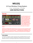
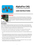
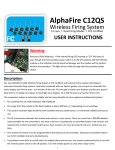
Sequencefire 24 Wireless Firing System 24 cues | Multi Firing Modes | Dual Power Modes | FCC Certified USER INSTRUCTIONS DISCLAIMER: The manufacturers, distributors, and sellers of this device accept no responsibility whatsoever for any damage, injury, or loss, financial or otherwise, resulting directly or indirectly from the use, misuse, function, or malfunction of this device. By purchasing and using this device you understand and accept this disclaimer. DESCRIPTION: Our new Sequencefire 24 Wireless Firing System represents the newest technology in consumer firing systems. And when combined with our Falcon igniters, allows you to put on a dramatic fireworks display just like the pros - at a fraction of the cost. Plus you get to watch your displays along with your guests! Now there is no longer any reason to hand light your displays. Do it like the pros at a fraction of the cost! This convenient system is extremely reliable and has many benefits of more expensive professional systems: FCC Certified (FCC ID: AYHFS2012) The range from the remote to the field module (receiver) is about 500 feet (+/-) depending on surroundings. The field module is programmable and may be reassigned to different Sequencefire 24 remotes. One Sequencefire 24 remote can control multiple Sequencefire 24 field modules in unison. The system has five firing modes: instant on-demand cue firing in any order, firing in stepped sequence, firing with time delays between all cues set equivalently, firing with time delays between all cues set arbitrarily, and firing all cues at once. Dual Power Modes: The field module operates on an internal rechargeable battery or can be connected to an optional external battery . The onboard timing sequencer allows the time delay between each cue to be set anywhere between 0.1 and 99.9 seconds. The firing system has a keyed safety and will not operate unless the key has been inserted and turned to the ON position. This system is highly sensitivity with excellent anti-jam performance. It is extremely reliable and easy to use. The RF transmission between the remote transmitters and receiver is very secure. Once a receiver is activated by a remote transmitter, that receiver will respond only to the transmitter it has been assigned to. 1 The remote transmitter comes with an on/off switch for added safety and security. You cannot inadvertently fire a cue with the remote power switch in the off position. Turn the remote power on only when ready to fire. The field module receiver has a 3-position switch for TEST, FIRE, and STANDBY. Charging circuit: The system comes with an internal charging circuit and plug-in wall charger. The internal charging circuit is only used to recharge the internal battery. The internal charging circuit will not charge an external battery. The wall charger will also not power the system for firing. Internal Circuit Overload Protection: The electrical circuitry of each cue is protected from thermal overload. Overloading can occur when there exists a short circuit in the wiring of igniters to the system. The Sequencefire 24 system, however, contains thermal overload circuit protection. So even if a short circuit exists in the wiring of the igniters to the system, thermal overload will not occur. Using a remote firing system like our Sequencefire 24 is much safer than lighting by hand. The Sequencefire 24 is a versatile and economical answer to a vast matrix of consumer wireless firing demands. Transmitter (Remote): Model: FS2012 (FCC Certified) FCC ID: AYHFS2012 Power: (2) 9V batteries (not included) Frequency: RF Radio 315.02 MHz Range: approximately 500 feet (+/-) depending on surrounding and other RF interference. Buttons: 16 buttons total. Dimensions: 3.875” x 8.125” x 1.375” Transmitter has an ON/OFF switch for added safety. The remote will not operate when in the OFF position, thereby eliminating the risk of an inadvertent button press. Receiver (Field Module): Model: SEQFIRE-24 Field Module: 1 containing 24 cues total Power: Internal rechargeable battery 12V, 3.2aH or optional external 12V 10 aH SLA battery Firing Current: > 1 A Test Current: 2 mA Dimensions: 10 .625” x 9” x 4” Firing Capacity: min. 5 Falcon Igniters per cue when wired in parallel 2 Components: 3 2 4 7 8 1 10 1 2 3 6 5 7 5 6 9 4 Description of Components: 1. Antenna Connection: allows for the detachable antenna to be connected to the system on the outside of the protective hard plastic case. 2. Cue Terminals: there are a total of 24 sets of cue terminals on the Sequencefire 24 system. Each cue consists of a red and black jack to which you connect igniters. It does not matter which wire of the igniter goes into which color jack. Receiver (Field Module) 3. Cue Lamps: Each cue has a lamp associated with it. These lamps are used for two purposes. When the system is in TEST mode, these lamps will turn ON indicating that that connected igniter has good continuity. When in FIRE mode these lamps will turn ON when the cue is being fired. 4. LCD Display: When the system is in STANDBY mode (the three-position switch in the center “0” position), the LCD will display the voltage being supplied by the internal or external battery. In other modes, the LCD display provides information regarding system status and programming. 5. Safety Key Switch: For added safety, the system will not operate unless the system key has been inserted into this switch and turned to the “ON” position. Switches between internal and optional external battery. 6. Three-Position Switch: TEST - used to test circuit continuity. FIRE - places system in FIRE mode. STANDBY (O) places the system into standby mode. 7. Programming Buttons: used to place the system into programming mode for programming the internal sequencer. Also used to place the system into STUDY mode allowing the system to be assigned or reassigned to a new remote. 3 8. Indicator Lamps: FULL—will turn on when the wall charger has been plugged in and the internal battery is fully charged. CHARGE—will turn on when the wall charger has been plugged in and the internal battery is charging. STUDY—will turn on when the system has been placed into STUDY mode and is receiving a signal from the remote transmitter. SIGNAL—will turn on when the system is receiving a signal from the remote transmitter. FIRE—will turn on when the system has been placed into FIRE mode. TEST—will turn on when the system has been placed into TEST mode. 9. Wall Charger Jack — plug the wall charger into this jack and into a standard wall outlet to recharge the internal battery. The wall charger will not charge an optional external battery. 10. External Battery Jack—use this jack to attach an external battery (optional) Components: Wall Charger Alligator Clip Cable Remote Transmitter External Battery (optional) Sequencefire 24 Field Module (Receiver) Notes: - Wall charger is for recharging the inner rechargeable battery only. It does not power the unit. - Alligator clip cable is for external battery connection. Red clip is for anode, black clip is for cathode. - The high capacity external battery is optional and recommended when firing more than one igniter per cue and for larger shows. 4 Before Use: Remote: Install two (2) 9V batteries in the remote by opening the battery compartment door on the back of the unit. Install the batteries inside of the compartment and replace the battery compartment door. Then turn on the remote by flipping the switch to the “on” position. The LED display on the remote should then read “P000.” Internal Field Module Battery: Before using your new firing system, please make sure to charge the internal battery completely by using the included wall charger. When the internal battery is fully charged, the FULL lamp on the face of the system will stay lit while the wall charger remains plugged into a power outlet. External SLA Battery (optional): If using the external battery option, also make sure the external battery is fully charged before use. To attach the external battery to the system, plug the alligator clip wire into the external battery jack (#10) and use the red alligator clip to connect to the positive (anode) terminal on the battery and use the black alligator clip to attach to the negative (cathode) terminal of the battery. How to Use: Powering On the Field Module Using the Internal or optional External Battery: 1. Make sure the three-position switch (#6) is in the STANDBY (O) position. 2. Insert the system key into the key switch (#5).Turn it to the INT position to use the internal battery or EXT to us an optional external battery. 3. The system will power on and the LCD display should show the current system voltage being supplied by the battery that has been selected for use. NOTE: ALWAYS MAKE SURE THE THREE POSITION SWITCH (#6) IS IN THE STANDBY (O) POSITION WHEN POWERING ON THE SYSTEM. NEVER POWER ON THE SYSTEM WITH THE THREE POSITION SWITCH IN THE FIRE POSITION AS ACCIDENTAL IGNITION COULD OCCUR, CAUSING POTENTIAL DAMAGE AND/OR INJURY. Assigning the remote transmitter to the field module: The Sequencefire 24 should arrive with the remote transmitter already assigned to the field module. Should you need to reassign the remote transmitter to the field module, or if you want to change the remote transmitter that the field module is assigned to, follow this procedure: 1. Power the system on as described in the “Powering On” section above. 2. Make sure the three-position (#6) switch is in the STANDBY (O) position. 3. Make sure the LCD screen reads “ALL TIME IS SAME” on the top row. If the LCD screen does not read “ALL TIME IS SAME” on the top row, press the MODE button until it does. 4. Press and hold the FIRE and OK buttons simultaneously on the remote transmitter. At the same time press and hold the STUDY button on the field module. After a few seconds release all buttons. 4. Confirm successful programming by pressing the FIRE and OK buttons on the remote transmitter. If both the SIGNAL and STUDY lamps light up on the field module, then the remote has been successfully assigned to the field module. IMPORTANT: NEVER ATTEMPT ANY PROGRAMMING OF THE SYSTEM WITH IGNITERS ATTACHED TO THE SYSTEM, AS ACCIDENTAL IGNITION COULD OCCUR, CAUSING POTENTIAL DAMGE AND/OR INJURY. 5 How to Use (continued): Programming the Internal Sequencer: You can program the internal sequencer in the field module to sequentially fire all 24 cues at predetermined time intervals between cues. The amount of time delay between each cue can be set anywhere between .1 second and 99.9 seconds. Once programmed, the remote transmitter can be used to start the sequence allowing the field module to fire the cues based upon the pre-programmed time internals without further involvement by the user. Programming the internal sequencer for all time intervals between cues to be equivalent: 1. Power on the field module as described in the “Powering On” section. 2. Make sure the three-position switch (#6) is in the STANDBY (O) position. 3. Press the MODE button on the field module until you see “ALL TIME IS SAME” displayed on the LCD screen. The time interval that is currently stored for use between all cues will also be displayed. 4. To change the time interval setting press the buttons labeled +10, +1, and +0.1. You may set the time to anything between .1 second and 99.9 seconds. 5. Once you have set the time delay to the desired amount, press the OK button to save the setting. 6. Now ALL the cues have been programmed with the exact same time delay between them. 7. Press the MODE button two times to exit the programming mode. Programming the internal sequencer with arbitrary time delays between cues: 1. Power on the field module as described in the “Powering On” section. 2. Make sure the three-position switch (#6) is in the STANDBY (O) position. 3. Press the MODE button on the field module until you see “01 TO 02” displayed on the LCD screen. The time interval that is currently stored for cue 01 to 02 is also displayed. 4. To change the time interval setting between cue 01 and 02 press the buttons labeled +10, +1, and +0.1. You may set the time to anything between .1 second and 99.9 seconds. 5. Once you have set the time delay to the desired amount, press the OK button to save the setting. 6. To set the time interval between other sets of cues press the NEXT button and follow the same procedure as outlined above. Use the NEXT and LAST buttons to move up and down between cues. 7. When finished, press the MODE button to exit the programming mode. WARNING: Only when no fireworks or igniters are connected to the firing system may the above procedures be performed. Never perform these procedures when fireworks are connected. Accidental ignition may occur, causing potential damage and/or injury. 6 How to Use (continued): Connecting Igniters to the Field Module: When connecting igniter wires to the field module, it does not matter which wire on the igniter goes into which terminal (red / black) on the field module cue. When connecting more than one igniter to any terminal on the module connect them in parallel. If you connect the igniters in series then the igniters may not fire. Testing Igniter Circuits: Once igniters have been attached to the cue terminals, it is important to test them to make sure the igniter circuits are good. 1. After connecting igniters to the cue terminals, power on the system as described earlier in the “Powering On” section. 2. Set the three-position switch (#6) to the TEST position. The TEST indicator lamp will turn on indicating the system is in TEST mode. 3. If the igniter circuit is good, the cue lamp (#3) for the cue will shine “green” indicating good continuity. If the green light does not turn on then the circuit is broken. Please check your wire connections. If your wire connections are sound, then the igniter is bad and will not fire. Replace the igniter and try again. Example: An igniter has been attached to cue 12 of the system and the LED light for cue 12 is shining green indicating good continuity for the cue. WARNING: NEVER attach igniters to the module when the module is powered on. Accidental ignition of igniters could occur and could pose a serious safety risk. Note: Do not connect more igniters to a field module than it can effectively fire. Connecting more than the specified number of igniters may overload the module and some or none of the igniters on the module may fire. 7 How to Use (continued): Firing Procedure: After your igniter circuits have tested as having good continuity, follow one of the following procedures for firing the cues: Instant on-demand cue firing in any order To fire individual cues on demand and in any order you desire: 1. Make sure the field module is powered on as described earlier in this manual. 2. Press the MODE button until the LCD screen reads “01 TO 02” or “ALL TIME IS SAME.” 3. On the field module set the three-position switch (#6) to the “FIRE” position. The LED display should read “WIRELESS INPUT- - - CAUTION - - -.“ The FIRE lamp on the field module will also turn on indicating the system is in FIRE mode. CAUTION: AT THIS POINT THE SYSTEM IS ARMED AND READY TO FIRE. 4. Turn on the remote transmitter. When powered on the remote should read “P000.” 5. To fire cue #1 - On the remote press the numbers 001 and then press the “FIRE” and “OK” buttons simultaneously. This will send the fire command for cue #1 to the field module and you will see the cue lamp for cue #1 on the field module light up indicating the cue has been fired. Next press the “C” button on the remote to ready the remote to fire the next cue. 6. To fire any of the remaining cues in any order, follow the same process as described in step 5 above. Firing In Stepped Sequence To fire the cues on-demand sequentially, starting with cue #1 and finishing with cue #24: 1. Make sure the field module is powered on as described earlier in this manual. 2. Press the MODE button until the LCD screen reads “01 TO 02” or “ALL TIME IS SAME.” 3. On the field module set the three-position switch (#6) to the “FIRE” position. The LED display should read “WIRELESS INPUT- - - CAUTION - - -.“ The FIRE lamp on the field module will also turn on indicating the system is in FIRE mode. CAUTION: AT THIS POINT THE SYSTEM IS ARMED AND READY TO FIRE. 4. Turn on the remote transmitter. When powered on the remote should read “P000.” 5. On the remote transmitter, press the STEP button. The LCD display on the remote will read STEP. 6. To fire the first cue, press the FIRE and OK buttons simultaneously on the remote. This will send the fire command to the first cue. The cue lamp for cue #1 will shine red indicating the cue has received the firing command. 7. Pressing the “FIRE” and “OK” buttons simultaneously again on the remote transmitter will fire the second cue. Follow this procedure to fire all remaining cues in sequence. Firing In Timed Sequence Using the Internal Sequencer Program To fire the cues sequentially using the internal sequencer with pre-programmed times: 1. Make sure the field module is powered on as described earlier in this manual. 2. Press the MODE button to choose which method of sequential firing you wish to use (either ALL TIME IS SAME or 01 TO 02 should be displayed on the LCD screen to choose whether you wish to fire the cues with all times between cues set equivalently to the time that has been stored previously or whether you wish to fire the cues using the arbitrary times that have been previously stored for each cue segment). 3. On the field module set the three-position switch (#6) to the “FIRE” position. The FIRE lamp on the field module will turn on indicating the system is in FIRE mode. CAUTION: AT THIS POINT THE SYSTEM IS ARMED AND READY TO FIRE. 4. Turn on the remote transmitter. When powered on the remote should read “P000.” 5. On the remote transmitter, press the CONT button. The LCD display on the remote will read CONT. 8 How to Use (continued): 6. On the remote press the FIRE and OK buttons simultaneously to start the sequence. This will send the start command to the internal sequencer of the field module and fire all cues in sequence according to the time intervals pre-programmed by the user. No further input is needed from the user. 7. To STOP the sequence, press the C button on the remote, then press the FIRE and OK buttons simultaneously. The sequence will be paused on the field module. To RESTART the sequence from the point where it was paused, press the CONT button on the remote, then press the FIRE and OK buttons simultaneously. The sequence will resume on the field module from the point it was paused. Example of Firing in Timed Sequence: Below is an example of firing in timed sequence. The first row represents the cue intervals. The second row represents the amount of time delay that has been programmed between the cue. The third row represents the total elapsed time of the display. All times are shown in seconds. Cue Interval 1-2 2-3 3-4 4-5 5-6 6-7 7-8 8-9 9-10 10-11 Interval (secs) 10 30 15 25 45 15 25 30 60 40 Elapsed (secs) - 10 40 55 80 125 140 165 195 255 Cue 11-12 12-13 13-14 14-15 15-16 16-17 17-18 18-19 19-20 20-21 Interval (secs) 10 30 15 25 45 15 25 30 60 10 Elapsed (secs) 295 305 335 350 375 420 435 460 490 550 Cue 21-22 22-23 23-24 End Interval (secs) 10 30 15 Elapsed (secs) 560 570 600 615 Firing All Cues at Once To fire all 24 cues at once: 1. Make sure the field module is powered on as described earlier in this manual. 2. Press the MODE button until the LCD screen reads “01 TO 02” or “ALL TIME IS SAME.” 3. On the field module set the three-position switch (#6) to the “FIRE” position. The LED display should read “WIRELESS INPUT- - - CAUTION - - -.“ The FIRE lamp on the field module will also turn on indicating the system is in FIRE mode. CAUTION: AT THIS POINT THE SYSTEM IS ARMED AND READY TO FIRE. 4. Turn on the remote transmitter. When powered on the remote should read “P000.” 5. On the remote transmitter, press the ALL button. The LCD display on the remote will read ALL. 6. On the remote press the FIRE and OK buttons simultaneously send the fire command to the field module and fire all cues at once. 9 SAFETY IS OUR MAIN PRIORITY: REMEMBER, SAFETY IS OUR PRIMARY CONCERN WHEN WORKING WITH FIREWORKS. REMOTE FIRING SYSTEMS CAN ADD AN ADDITIONAL LEVEL OF SAFETY TO IGNITING FIREWORKS, BUT THE RISKS OF ACCIDENTAL IGNITION STILL REMAIN EVEN WITH THE REMOTE FIRING SYSTEM’S USE. PLEASE, MAKE SURE ALL FIELD MODULE AND REMOTE TRASMITTER POWER SWITCHES ARE IN THE OFF POSITION RIGHT UP UNTIL THE TIME YOUR DISPLAY IS ABOUT TO BEGIN. THIS NOT ONLY SAVES ON BATTERIES, BUT HELPS TO PREVENT ACCIDENTAL IGNITION FROM AN INADVERTENT BUTTON PRESS. PLEASE REVIEW OUR COMMON SENSE SAFETY GUIDELINES LOCATED AT: http://www.fireworks.us Quantum Products, Inc. www.Fireworks.us www.FiringSystems.us Email: [email protected] 10