1
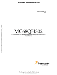
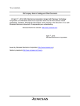
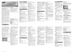
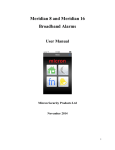
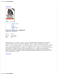
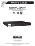
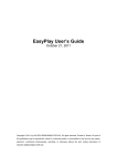
PIKA dsPTX
USER MANUAL
PIKA Technologies Inc.
1.09
PIKA TECHNOLOGIES INC.
155 Terrence Matthews Crescent
Kanata, Ontario K2M 2A8
Canada
Tel: 1-613-591-1555
Fax: 1-613-591-1488
(c) Copyright 1989 - 1995 PIKA Technologies Inc.
All rights reserved. No part of this document may be reproduced, stored in a retrieval system, or in any other form or by any
means, electronic, mechanical, photocopying, recording or otherwise, without prior written permission of PIKA Technologies
Inc.
This Printing: June 1995
Table of Contents
1 DSPTX HARDWARE ............................................................................................................................................. 1
1.1 DSPTX/SOLO .................................................................................................................................................... 1
1.1.1 Features .................................................................................................................................................... 1
1.1.2 Overview ................................................................................................................................................... 1
1.1.3 Power Connections ................................................................................................................................... 2
1.1.4 Telephone line Connections ..................................................................................................................... 2
1.1.5 Special Mounting Considerations ............................................................................................................. 4
1.1.6 Remote Login ............................................................................................................................................ 5
1.2 DSPTX-I PC CARD............................................................................................................................................ 6
1.2.1 Card Base I/O Address ............................................................................................................................. 7
1.2.2 Phone Line Connection............................................................................................................................. 8
2 RUNNING THE DSPTX SOFTWARE........................................................................................................................ 9
2.1 CONFIGURATION FILES .................................................................................................................................... 10
2.1.1 NFSTART.CFG ....................................................................................................................................... 10
2.1.2 FSTART.CFG.......................................................................................................................................... 10
2.1.3 NFDPSTRT.CFG .................................................................................................................................... 10
3 CUSTOMIZING DSPTX OPERATION .................................................................................................................... 11
3.1 OPERATING MODE ........................................................................................................................................... 12
3.1.1 Mode ....................................................................................................................................................... 12
3.1.2 Connection type ...................................................................................................................................... 12
3.2 CARD SETTINGS .............................................................................................................................................. 13
3.2.1 Card Base Address.................................................................................................................................. 13
3.2.2 dsPTX channels per card ........................................................................................................................ 13
3.3 COUNTRY OPTIMIZATION ................................................................................................................................ 14
3.3.1 DSP Base Address................................................................................................................................... 14
3.3.2 Country ................................................................................................................................................... 14
3.3.3 Optimization Mode.................................................................................................................................. 14
3.4 CALL START HANDLING .................................................................................................................................. 15
3.4.1 Channel Numbers.................................................................................................................................... 15
3.4.2 Channel always active ............................................................................................................................ 15
3.4.3 Call start on ringing................................................................................................................................ 15
3.4.4 Ringing Voltage Debounce ..................................................................................................................... 15
3.4.5 Wait After Ringing .................................................................................................................................. 15
3.4.6 Call Start On Local Off Hook ................................................................................................................. 15
3.4.7 Local Off Hook Debounce....................................................................................................................... 16
3.4.8 Activate after local off hook debounce.................................................................................................... 16
3.4.9 Maximum interdigit time ......................................................................................................................... 16
3.4.10 Wait for pulse digit after local flash...................................................................................................... 16
3.5 CALL END HANDLING ..................................................................................................................................... 17
3.5.1 Channel Numbers.................................................................................................................................... 17
3.5.2 Deactivation Condition ........................................................................................................................... 17
3.5.3 Deactivation Timing................................................................................................................................ 18
3.5.4 Signal Energy Threshold......................................................................................................................... 18
3.5.5 Pulse Sequence........................................................................................................................................ 18
3.5.6 Maximum CO Feed off............................................................................................................................ 18
3.6 DTMF OUTPUT .............................................................................................................................................. 19
3.6.1 Channel Number ..................................................................................................................................... 19
3.6.2 Digit Translation..................................................................................................................................... 19
3.6.3 Transmit Grouping.................................................................................................................................. 20
3.6.4 Inactivity time-out ................................................................................................................................... 20
3.6.5 Block first digit........................................................................................................................................ 20
3.6.6 Digit Masking.......................................................................................................................................... 21
3.6.7 DTMF Parameters .................................................................................................................................. 21
3.7 VOICE RESPONSE OPERATION ......................................................................................................................... 22
3.7.1 Channel Number ..................................................................................................................................... 22
3.7.2 Voice Response Enable ........................................................................................................................... 22
3.7.3 Voice Response Files .............................................................................................................................. 22
3.7.4 Directory ................................................................................................................................................. 22
3.8 DETECTOR CONTROL ...................................................................................................................................... 23
3.8.1 Channel Numbers.................................................................................................................................... 23
3.8.2 Report time-out period ............................................................................................................................ 23
3.8.3 Local to CO signal gain .......................................................................................................................... 23
3.8.4 CO to Local signal gain .......................................................................................................................... 23
3.8.5 Double talk detector enable / disable...................................................................................................... 23
3.8.6 Minimum double talker detector clipping threshold ............................................................................... 24
3.8.7 Double talker activation threshold.......................................................................................................... 24
3.8.8 Use double talk learning ......................................................................................................................... 24
3.9 LOG FILE GENERATION ................................................................................................................................... 25
3.9.1 Log Flags ................................................................................................................................................ 25
3.9.2 Logging All Channels ............................................................................................................................. 25
3.9.3 Logging One Channel ............................................................................................................................. 25
3.9.4 Maximum Log Size .................................................................................................................................. 25
3.9.5 Log Directory.......................................................................................................................................... 25
3.9.6 Enable echo canceller diagnostics.......................................................................................................... 25
4 DSPTX APPLICATION ENVIRONMENT ................................................................................................................ 26
4.1 COMMAND WINDOW .............................................................................................................................. 26
4.2 STATUS WINDOW..................................................................................................................................... 26
5 TROUBLE SHOOTING .......................................................................................................................................... 27
5.1 System Grounding ...................................................................................................................................... 27
5.2 Wiring ........................................................................................................................................................ 27
5.3 Configuration File ..................................................................................................................................... 27
5.4 Loop Instability .......................................................................................................................................... 27
5.5 Cut thru improvements............................................................................................................................... 28
5.6 Poor speech quality.................................................................................................................................... 28
5.7 Low or inconsistent speech levels .............................................................................................................. 29
1 dsPTX Hardware
The dsPTX Pulse to DTMF converter is based on state of the art digital signal processing (DSP)
technology. The dsPTX is available either as a 4/8 port standalone unit (dsPTX/Solo), or as a PC
based peripheral card (dsPTX-i), compatible with any 286 or better PC, running DOS 3.0 or higher.
1.1 dsPTX/Solo
The dsPTX/Solo is available in four line (dsPTX-4/Solo) or eight line (dsPTX-8/Solo) versions and is
contained in a standalone box suitable for both desktop and wall mount applications. It is
accompanied by an external power supply.
1.1.1 Features
•
•
•
4 or 8 lines of pulse to tone conversion
small 3”X8”X6” industrial chassis suitable for desktop or wall mounting
remote login feature allows software updates as well as diagnostics through modem/direct
connection by a Pika technician or developer
1.1.2 Overview
1.
3.
6.
2.
4.
5.
.
1
2
3
4
5
6
Power light
Power connector
Com1
Com2
Ext keyboard
Telephone line jacks
dsPTX User Manual
Active when ON
+5v/+12v/-12v from external supply
Used for remote login
Not used
Not used
Up to 8 pulse channels
1
1.1.3 Power Connections
Power is delivered by an external power supply and is connected as follows. The unit requires +12v, 12v, and +5v.
+5v
NC
5 pin DIN plug keyed
with external power
supply connector
-12v
+12
GND
GN
1.1.4 Telephone line Connections
Each pulse to tone conversion channel is equipped with a pair of connections, telephone line “in”
which connects to the PBX or Public network, and “local” line connected to the host system (i.e.
receiving DTMF digits). The connectors are wired in RJ-14 style, compatible with most standard PC
based voice cards. The location of each “in”/”local” pair is as shown in the figure below.
The following diagram illustrates telephone line connector assignments (dsPTX-8/Solo):
Channel 1 “in” line
Channel 0 “in” line
Channel 1 “local” line
Channel 0 “local” line
Channel 3 “in” line
Channel 2 “in” line
Channel 3 “local” line
Channel 2 “local” line
dsPTX User Manual
Channel 5 “in”
Channel 4 “in”
Channel 5 “local” line
Channel 4 “local” line
Channel 7 “in”
Channel 6 “in”
Channel 7 “local” line
Channel 6 “local” line
2
The following diagrams illustrate actual wiring of telephone lines onto the dsPTX/Solo:
PIKA
dsPTX-4/Solo
IN 0+1
PBX/NETWORK
Local 0+1
LINES
IN 2+3
Local 2+3
HOST APPLICATION
(Typically Voice Cards)
Phone line connectors (RJ-14 style)
First Pair
dsPTX User Manual
Second Pair
3
1.1.5 Special Mounting Considerations
dsPTX User Manual
4
1.1.6 Remote Login
Remote login is used for field debuging, customizing dsPTX/Solo operation, or uploading software
updates. The COM1 serial interface port of the dsPTX/Solo is used for remote login access. The
COM1 port can be connected either to any PC running a communications package via a null modem
cable, or directly to an external MODEM for dial-in access via the telephone network.
When logged in externally. the remote terminal device essentially becomes the keyboard and monitor
for the dsPTX/Solo, thereby giving users full access to dsPTX output, configuration files, and logging
capabilities of the unit, as described in sections 2, 3 and 4 of this manual.
PC Connection
A three wire connection is necessary to communicate with the dsPTX unit. The term for such a
connection is known as a null modem and contains the following three signals:
RXD - Receive data (pin 2 on dsPTX)
TXD - Transmit data (pin 3 on dsPTX)
GND - Ground (pin 5 on dsPTX)
Do not forget the crossing of the RXD and TXD signals as shown below:
The data transfer mode used by the dsPTX is 9600 baud, no parity, 8 data bits, 1 stop bit. The
terminal package on the PC must be set for this in order to recognize the information coming from the
dsPTX/Solo.
dsPTX/Solo COM port 1
RXD pin 2
RXD
TXD pin 3
TXD
GND pin 5
GND
PC
MODEM Connection
A three wire connection is necessary to communicate with the dsPTX/Solo unit.
RXD - Receive data (pin 2 on dsPTX)
TXD - Transmit data (pin 3 on dsPTX)
GND - Ground (pin 5 on dsPTX)
In the case of a dial-in connection, a MODEM is required at both ends of the connection. The
MODEM connected to the dsPTX should be configured as follows:
- Auto answer
- DTR override
The data transfer mode used by the dsPTX/Solo is 9600 baud, no parity, 8 data bits, 1 stop bit. The
terminal package on the PC must be set for this in order to recognize the information coming from the
unit.
dsPTX/Solo COM port 1
Modem
RXD pin 2
TXD pin 3
GND pin 5
dsPTX User Manual
Modem
Tel.
Network
TXD
RXD
PC
GND
5
1.2 dsPTX-i PC Card
The dsPTX is available as an internal PC peripheral card, in two line (dsPTX-2i) or four line (dsPTX4i) formats, and can be inserted in any free 8-bit or 16-bit slot of the host PC, and requires no
interrupts.
Base
Address
DIPSwitch
PHONE
LINES
IN 0+1 ( Far End or "CO")
OUT 0+1 (Near End or "IVR")
PIKA
dsPTX-4i PC Card
dsPTX User Manual
IN 2+3 (Far End or "CO")
OUT 2+3 (Near End or "IVR")
6
1.2.1 Card Base I/O Address
The dsPTX-i card occupies 32 consecutive I/O addresses of the PC bus, and no system memory
space. The start or Base address is user selectable, ensuring no conflicts with any type of peripheral
card. Each dsPTX-icard in the system is set to a different base address by using the BASE ADDRESS
dipswitch located conveniently at the top of the card as shown:
Base Address Switch (TOP VIEW)
UP
1
2
3
4
DOWN
CIRCUIT BOARD
1
D
D
D
D
D
D
D
D
U
U
U
U
U
U
U
U
2
D
D
D
D
U
U
U
U
D
D
D
D
U
U
U
U
3
D
D
U
U
D
D
U
U
D
D
U
U
D
D
U
U
4
D
U
D
U
D
U
D
U
D
U
D
U
D
U
D
U
BASE ADDRESS
0x200
0x220
0x240
0x260
0x280
0x2A0
0x2C0
0x2E0
0x600
0x620
0x640
0x660
0x680
0x6A0
0x6C0
0x6E0
Notes on Base address selection:
For historical reasons, the PC architecture defined by IBM restricts peripheral cards (i.e. non
motherboard based devices) to using I/O addresses in the range 0x200 to 0x3FF, although the
286/386/486 processors actually support 16 bit I/O (0x0000 to 0xFFFF).
The PIKA cards overcome this address space limitation by decoding the entire I/O address bus (A15A0), providing paging into addresses above the standard range (i.e. 0x600 and above).
Some older peripheral cards ignore address lines A10 to A15, meaning that these cards will decode
addresses 0x600 to 0x6E0 as addresses 0x200 to 0x2E0. Selecting base addresses above 0x600
may not resolve conflicts between a PIKA card and other cards.
The following figure illustrates how the PC’s I/O addresses are decoded by different cards:
Description
Standard decoding
PIKA Low addresses
PIKA High addresses
dsPTX User Manual
A15-A11
X
X
X
A10
X
0
1
A9
1
1
1
A8
0
0
0
Decoded Address
(0x200-0x2FF) +(0x600-0x6FF)
0x200-0x2FF
0x600-0x6FF
7
1.2.2 Phone Line Connection
The line interface to the dsPTX-i PC card is made by connecting the inputs in series with the target
(host) system lines as shown below:
IN 0+1
PBX/NETWORK
PIKA dsPTX
OUT 0+1
LINES
IN 2+3
OUT 2+3
HOST APPLICATION
Phone line connectors (RJ-14 style)
Line 0 or 2
dsPTX User Manual
Line 1 or 3
8
2 Running the dsPTX Software
The dsPTX hardware is driven by a DOS application program DSPTXDRV which can be run either as
a dedicated application or as a background DOS TSR (Terminate and Stay Resident).
DSPTXDRV is run from the DOS command line as follows:
DSPTXDRV [config file]
The operation of the DSPTXDRV application is set up by a configuration file. The default file name is:
‘DSPTX.CFG’, which is used if the configuration file is not specified on the command line. The
configuration file is a user definable text file which controls various parameters and modes of
operation of the dsPTX. Most Parameters can be setup either on a system or a per channel basis.
Section 3 of this manual describes the available dsPTX configuration options.
NOTES:
• Any of the parameters listed may be omitted from the configuration file, permitting the
application to use default values.
•
The configuration files will need to be modified to setup the base address of the card(s) in
the system, or if the dsPTX driver is to run as a standalone application rather than a TSR.
A template configuration file TEMPLATE.CFG is also provided. This template file is a copy of the
original DSPTX.CFG.
dsPTX User Manual
9
2.1 Configuration files
Three standard configuration files are provided. These files typically require modification at installation
time to indicate the base address of the dsPTX card in the system. Template versions of these files
are provided: NFTMPLT.CFG, FTMPLT.CFG, and NFDPTMPL.CFG.
These template files are a copy of the original configuration files, allowing them to be modified without
destroying the originals. Configuration files with other names can be created and
used as required.
2.1.1 NFSTART.CFG
This file is identical to dsptx.cfg. This configuration is typically used in most situations, allowing the
dsPTX to remain active both on incoming and outgoing calls.
This configuration file supports pulse detection both on incoming and outgoing calls. Incoming calls
are indicated by ringing voltage followed by a local offhook, and outgoing calls are indicated by local
offhook ( not preceded by ringing). Near end originated calls may dial out using DTMF dialing, but
may not use pulse dialing.
Dial pulsing by the near end may not occur following a near end hook flash.
2.1.2 FSTART.CFG
This configuration file only supports pulse detection on incoming calls, allowing the dsPTX to remain
idle on outbound calls. This configuration is typically used in trunk side connections (i.e. on the public
network lines).
Incoming calls are indicated by ringing voltage followed by a local offhook, and outgoing calls are
indicated by local offhook ( not preceded by ringing).
Dial pulsing by the near end may not occur following a near end hook flash.
2.1.3 NFDPSTRT.CFG
This configuration file supports pulse detection both on incoming and outgoing calls. This
configuration allows the near end originated calls to be dialed out using either DTMF or dial pulsing.
Incoming calls are indicated by ringing voltage followed by a local offhook, and outgoing calls are
indicated by local offhook ( not preceded by ringing).
Dial pulsing by the near end may occur after a hook flash.
dsPTX User Manual
10
3 Customizing dsPTX Operation
The text file DSPTX.CFG contains the configuration parameters for the dsPTX card. The configuration
file can be edited manually to change configuration parameters. Comment lines, starting with a semicolon may be included anywhere in the file. Default values are shown as bold text in each section of
this manual, and will be used for any parameters which are omitted.
The configuration file is separated into different sections. The sections currently supported are
[operating mode] [ptx card] [country optimization] [call start handling] [call end handling]
[voice response] [dtmf output] [detector control] and [log file generation].
All parameters in the sections [call handling] [activation deactivation][dtmf output] and [detector
control] may be specified either globally or on a per channel basis. In each section, all global
parameters must be specified first. Any channel specific parameter may the be specified following the
parameter "channel=n" where n is the channel number. Channels are numbered consecutively
starting at 0 starting on the dsPTX card specified in the first [ptx card] section. If the first card is a 2
channel card and the second card is a 4 channel card, the first card would have channels 0 - 1 and
the second card would have channels 2 - 5 and so on. The parameters in the section [country
optimization] may be either specified globally or on a per DSP basis. The global parameters must be
specified first and any DSP specific parameters may be specified at the end of the section, following
the parameter "dsp_ptx_base_address=n" where n is the base address of the card containing the
DSP which will be used.
dsPTX User Manual
11
3.1 Operating mode
This section defines the operating mode of the dsPTX driver. This section may appear only once in
this file
[operating mode]
3.1.1 Mode
The driver may be loaded as an application or as a TSR (terminate and stay resident) program. If the
driver is loaded as a TSR, the dsPTX may be used with other DOS applications.
In the TSR mode of operation, the command and status screen are not available and no logging is
performed.
If the dsPTX driver is run as a dedicated application, the status screen is available and logging can
be performed. In this mode of operation the dsPTX can be used for trouble shooting, performance
monitoring and becoming familiar with dsPTX operation. In application mode, the driver can be run
from the timer interrupt or it may run in the background. Better performance can be expected if the
driver is run from the timer.
1. TSR (Terminate and Stay Resident) = 0
2. Application with driver on timer interrupt = 1
3. Application with driver running in background = 2 (Debug only, should normally not be
used)
default: mode_of_operation=0
3.1.2 Connection type
The dsPTX may be connected either in bridged mode or in series with the line.
In series mode, the dsPTX is placed in series with the telephone line being monitored. Dial pulse
signals are received on the “in” line input and DTMF tones are transmitted on to the “local” line.
Series mode connections are required to support enhanced cut thru operation.
In bridged mode, the channel “in” line inputs are bridged across the line being monitored, and the
nothing is connected to the “local” line inputs. In this mode, the line remains on hook and does not
draw any loop current except when a tone or voice prompt is being played on the line. Bridged mode
does not support enhanced cut thru operation and should only be used if cut thru detection is not
required.
1. Series mode = 0
2. Bridged mode = 1
default: connection_mode=0
dsPTX User Manual
12
3.2 Card Settings
This section defines settings for each dsPTX card in the system, and must be repeated for each
dsPTX card in the system:
[ptx card]
3.2.1 Card Base Address
Base address of the card. The address must be specified in HEX, and it must match the DIPSWITCH
setting on the card.
default: ptx_base_address=200
3.2.2 dsPTX channels per card
The dsPTX card can be configured to support 1 to 4 channels. If fewer than 4 channels are enabled,
the lower numbered channels will be enabled and the higher numbered channels will be disabled.
default: number_of_channels_on_card=4
dsPTX User Manual
13
3.3 Country Optimization
This section defines how the performance of the pulse detector is optimized, and should appear only
once in the configuration file.
[country optimization]
3.3.1 DSP Base Address
The parameters specified in this section apply to all dsPTX channels in the system, unless parameter
dsp_ptx_base_address=n appears first, in which case all following parameters will affect only those
channels which use the DSP on the specified card. To assign unique values to different DSPs,
dsp_ptx_base_address=n can be repeated, with each instance superseding the previous one.
NOTE: value for this parameter must be in hex.
default: dsp_ptx_base_address=200
3.3.2 Country
The country for which the dsPTX is optimized. The countries which are currently supported are:
World = “wo”.
default: country="wo"
3.3.3 Optimization Mode
The type of performance for which the dsPTX is to be optimized.
The current list includes.
1. Balanced=“ba”
2. Talk-off=“to”
3. Talk-off and Cut-thru=“tc”
default: optimization="to"
dsPTX User Manual
14
3.4 Call Start Handling
This section determines how the dsPTX will handle the start of a call, and should appear only once in
the configuration file.
[call start handling]
3.4.1 Channel Numbers
The parameters specified in this section apply to all channels in the system, unless parameter
channel=n appears first. If the parameter channel=n appears, all following parameters will affect only
that specific channel. To assign unique value to different channels, channel=n can be repeated.
Each instance of channel=n supersedes the previous one.
3.4.2 Channel always active
When a PTX channel is always active, it continuously monitors and reports dial pulse signals. When
the PTX always active flag is set, other call start handling and call end handling parameters have no
affect. This parameter should be set to 1 only when ringing is not available to signal the start of a call.
1. Monitoring starts and stops using call start and call end parameters=0
2. Channel is always active=1
default: ptx_always_active=0
3.4.3 Call start on ringing
When activated, a new call is started when ringing is detected.
1. Do not start call on ringing=0
2. Start call on ringing=1
default: start_call_on_ringing=1
3.4.4 Ringing Voltage Debounce
The minimum period is used to debounce the ringing signal to eliminate spurious ringing detections
due to noise. If the debounce period is to large, the far end can answer before ringing is detected.
This period is specified in milliseconds.
default: ringing_debounce_period_msec=150
3.4.5 Wait After Ringing
In series mode, if the local off hook condition is not detected within the specified period, the dsPTX will
behave as if the call was not answered go back to the idle state and wait for the next call. In bridged
mode, pulse detection will be activated after ringing has been removed for specified period.
default: wait_after_ringing_msec=5000
3.4.6 Call Start On Local Off Hook
When activated, a new call is started when local off hook is detected (unless start_on_ringing = 1 and
ringing is detected first). This parameter is not used in bridged mode.
1. Do not start call on local off hook=0
2. Start call on start call on local off hook=1
default: start_call_on_local_off_hook=1
dsPTX User Manual
15
3.4.7 Local Off Hook Debounce
The minimum period is used to debounce the local off hook signal to eliminate spurious local off hook
detections due to noise. The value should be longer than the CO requires to detect the local off hook
condition. This will prevent spurious detections when the CO disconnects the ringing generator. This
parameter is not used in bridged mode or when start_call_on_local_off_hook = 0. This period is
specified in milliseconds.
default: local_off_hook_debounce_period_msec=1000
3.4.8 Activate after local off hook debounce
Pulse detection can be activated immediately after the local off hook signal has been debounced, or
activation can occur only after local end pulse dialing has been completed. Activation immediately
after the debounce should be used unless the local end can initiate a call with pulse dialing. Activation
after pulse dialing should occur whenever pulse dialing will be used, since the pulse digits will not
propagate through the line split configuration which is present when pulse detection is active. This
parameter is not used in bridged mode.
1. Activate after pulse dialing complete=0
2. Activate after local off hook debounce=1
default: activate_after_local_off_hook_debounce=1
3.4.9 Maximum interdigit time
When the time since the last local end dial pulse exceeds the maximum interdigit time, the dsPTX
splits the line and starts detecting far end dial pulses. This parameter is only used if the local end can
dial pulse at the start of a call or following a hook flash.
default: maximum_interdigit_time_msec=2000
3.4.10 Wait for pulse digit after local flash
This parameter must be set to a value greater than 0 when the local end must be capable of pulse
dialing during a call, after sending a hook flash. This parameter specifies the maximum delay from
the end of the hook flash to the start of the first pulse digit. If no pulse dialing occurs within this
period, the dsPTX returns to the digit detection state.
default: local_wait_to_dial_after_flash_msec=0
dsPTX User Manual
16
3.5 Call End Handling
This section defines the conditions for the deactivation of the dsPTX and should appear only once in
the configuration file.
[call end handling]
3.5.1 Channel Numbers
The parameters specified in this section apply to all channels in the system, unless parameter
channel=n appears first. If the parameter channel=n appears, all following parameters will affect only
that specific channel. To assign unique values to different channels, channel=n can be repeated.
Each instance of channel=n supersedes the previous one.
3.5.2 Deactivation Condition
The dsPTX can be deactivated as a result of one or more conditions. Deactivation is the end of a call.
Dial pulse detection will only be reactivated at the start of the next call. If the connection mode is
bridged, the local_on_hook_deactivation and the co_loop_current_off_deactivation conditions are not
used. If connection mode is series, ringing_deactivation is not used. Deactivation conditions are
listed below (a "0" indicates the condition is not used and a "1" indicates the condition is used):
1. Local on hook detected, this condition should normally be debounced to differentiate between a
hook flash and true hang-up (Used only in series connection mode):
default: local_on_hook_deactivation=1
2. CO loop current off (Used only in series connection mode)::
default: co_loop_current_off_deactivation=1
3. On detection of ringing (Used only in bridged connection mode):
default: ringing_deactivation=1
4. After a period of no detected pulse digits:
default: no_pulse_digit_period_deactivation=0
5. After a given period of no energy on the line:
default: no_signal_energy_period_deactivation=0
6. A given period after activation
default: activation_period_deactivation=0
7. On reception of a pulse digit sequence
default: pulse_digit_sequence_deactivation=0
8. On receipt of any DTMF digit:
default: any_dtmf_deactivation=0
9. On DTMF received before any DTMF digit transmitted:
default: dtmf_first_deactivation=0
dsPTX User Manual
17
3.5.3 Deactivation Timing
The deactivation time-out periods are specified in milliseconds. The first no pulse period used may be
different than the remaining no pulse periods time-outs. The first no energy period used may be
different than the remaining no energy periods used. The following parameters are provided:
defaults:
local_on_hook_debounce_period_msec=1500
first_no_pulse_digit_period_msec=20000
no_pulse_digit_period_msec=120000
first_no_energy_period_msec=15000
no_energy_period_msec=10000
activation_period_msec=300000
3.5.4 Signal Energy Threshold
Signal energy detection threshold in dBm0. When deactivation on no signal energy is enabled,
deactivation will occur when the signal energy is below the threshold for the no_energy_period. This
number must be specified as an integer.
default: energy_detection_threshold_dbm0=-45
3.5.5 Pulse Sequence
A sequence of 1 or 2 pulse digits can be used to deactivate the receiver. For example
deactivation_pulse_sequence = 7,9 indicates that the dsPTX channel is to be deactivated when the
digit sequence 7, 9 is detected.
default: deactivation_pulse_sequence=8
3.5.6 Maximum CO Feed off
This parameter is used only when the local end can start a call. The CO signals the end of a call by
removing the CO feed current for a short period (typicaly 500mSec). The dsPTX can use this signal
to detect the end of a call. The amount of time that the CO removes this current must be less than
the value of this parameter. If the local end goes on hook at the same time that the CO removes the
loop feed current, it must remain on hook longer than this parameter value. If this parameter is to
large, the dsPTX may miss a local on hook condition and remain idle for the duration of the next call.
If this parameter is to small, the dsPTX will immediately reactivate its self.
default: max_co_feed_off_msec=2000
dsPTX User Manual
18
3.6 DTMF Output
This section defines the DTMF output characteristics and operation of the dsPTX, and should appear
only once in the configuration file.
[dtmf output]
3.6.1 Channel Number
The parameters specified in this section apply to all channels in the system, unless parameter
channel=n appears first. If the parameter channel=n appears, all following parameters will affect only
that specific channel. To assign unique value to different channels, channel=n can be repeated.
Each instance of channel=n supersedes the previous one.
3.6.2 Digit Translation
Normally the DTMF tone which is transmitted, will be the same as the received pulse digit. However,
remapping of pulse digits will allow support of DTMF digits "*" and "#". A DTMF digit will be sent in
response to 1 or 2 received pulse digits. If a dtmf digit cannot be generated, a negative number
should be specified. A pulse digit which forms a one digit sequence may not start a 2 digit sequence.
dtmf_sequence*=9,7 will result in the DTMF signal * being sent when pulse digit
sequence 9, 7 is received.
defaults:
Example:
dtmf_sequence0=0
dtmf_sequence1=1
dtmf_sequence2=2
dtmf_sequence3=3
dtmf_sequence4=4
dtmf_sequence5=5
dtmf_sequence6=6
dtmf_sequence7=7
dtmf_sequence8=8
dtmf_sequence9=9
dtmf_sequence*=-1
dtmf_sequence#=-1
dtmf_sequenceA=-1
dtmf_sequenceB=-1
dtmf_sequenceC=-1
dtmf_sequenceD=-1
dsPTX User Manual
19
3.6.3 Transmit Grouping
DTMF transmit grouping. If dsPTX can collect more than one digit at the start of a call before these
digits need to be forwarded, then ‘backward learning’ can be used. Backward learning can
significantly decreases the error rate, by comparing the parameters of the first digit to the second and
possibly the third digit, and rejecting the first digit if it's parameters are significantly different. The digit
counts refer to the number of transmitted DTMF digits, and not the number of received pulse digits.
The transmit grouping is specified using the format: transmit_grouping = NH,NH,NH... There may no
more than 10 groups. Where N is the number of transmitted DTMF digits in the group and H indicates
how the group is to be handled. A group can be handled in one of two ways:
I - send all digits in the group immediately after all digits in the group have been received. A group of
this type may have at most 24 digits.
T - send any received digits after an inactivity time-out and send any unsent digits immediately after all
digits for the group have been received. A buffer may hold at most 24 digits. If the buffer is full all
received digits will be forwarded even if there is no time-out.
Example 1:
transmit_grouping =3000T
Transmit all digits in the queue whenever there is an inactivity time-out. A value greater than 1000 is
taken to mean that the group includes all digits in the call.
Example 2:
transmit_grouping = 4T,2I,1I
Transmit the first 4 digits when they have all be received or if the inactivity time-out expires first,
transmit all digits in the queue. Transmit the next two digits when they have both been received.
Transmit all remaining digits as soon as each is received. Once all digit groups have been used, the
last digit group is used repeatedly until the end of the call.
More examples:
transmit_grouping = 2000T
transmit_grouping = 4T,1I
default: transmit_grouping = 1I
3.6.4 Inactivity time-out
The inactivity time-out for the transmit grouping is specified in mSec
default: inactivity_timeout_for_transmit_grouping_msec = 4000
3.6.5 Block first digit
The first pulse digit received in a call can be blocked. This allows a training pulse digit to be absorbed
by the dsPTX. digit not blocked=0, digit blocked=1
default: block_first_pulse_digit = 0
dsPTX User Manual
20
3.6.6 Digit Masking
The reliability of the dsPTX can be increased if some digits can be eliminated from the set of
possible first pulse digits in a call. The most common digits detected incorrectly at the start of a call
are 1, 2 and 3. Possible parameter values are: allow as first pulse digit in call=0, do not allow as first
pulse digit in call=1.
Example 1:
Given, the following parameter list:
block_first_pulse_digit = 1
ignore_first_pulse_digitN = 1 (for N=0 and N=1)
ignore_first_pulse_digitN = 0 (for N=2..9)
and given the first three received pulse digits are 7, 1, 6 then the digits 7 and 1 would be ignored and
the first pulse which would be used is 6.
Example 2:
For the same set of parameters as example 1, and given the following sequence of received pulse
digits: 1, 0, 1, 9 then the digits 1, 0 and 1 would be ignored, and the first pulse digit which would be
used would be 9.
Example 3:
For the same set of parameters as example 1, and given the following sequence of received pulse
digits: 1, 9 the digit 1 would be ignored and the digit 9 would be used.
defaults:
ignore_first_pulse_digit0 = 0
ignore_first_pulse_digit1 = 0
ignore_first_pulse_digit2 = 0
ignore_first_pulse_digit3 = 0
ignore_first_pulse_digit4 = 0
ignore_first_pulse_digit5 = 0
ignore_first_pulse_digit6 = 0
ignore_first_pulse_digit7 = 0
ignore_first_pulse_digit8 = 0
ignore_first_pulse_digit9 = 0
3.6.7 DTMF Parameters
The DTMF output signal parameters can be specified. These parameters may only be specified on a
global basis. The DTMF row tones are the low and DTMF column tones are the high frequency tones.
defaults:
dtmf_row_output_level_dbm0=-18
dtmf_col_output_level_dbm0=-18
dtmf_on_time_duration_msec=100
dtmf_off_time_duration_msec=100
dsPTX User Manual
21
3.7 Voice Response Operation
This section defines the dsPTX voice response operation. If voice response is enabled, a voice
message will immediately be played out onto the phone line whenever a pulse digit is detected. This
will also allow voice confirmation of dialed digits. Voice response occurs for all received pulse digits,
including blocked and ignored digits. If voice response and DTMF transmission can occur at the same
time, voice response occurs first. Voice responce is not available in the TSR mode of operation.
[voice response]
3.7.1 Channel Number
Voice response operation may be enabled or disabled on a per channel basis by using the channel=n
command. The only one set of voice files may be specified. These voice files must be specified on a
global basis.
3.7.2 Voice Response Enable
Enable or disable voice response by the dsPTX to detected pulse digits. Voice response disabled = 0,
voice response enabled = 1.
default: voice_response_enabled=0
3.7.3 Voice Response Files
A different voice response file will be played for each received pulse digit. These files are:
voice_response_file0="r_zero.vox"
voice_response_file1="r_one.vox"
voice_response_file2="r_two.vox"
voice_response_file3="r_three.vox"
voice_response_file4="r_four.vox"
voice_response_file5="r_five.vox"
voice_response_file6="r_six.vox"
voice_response_file7="r_seven.vox"
voice_response_file8="r_eight.vox"
voice_response_file9="r_nine.vox"
3.7.4 Directory
If the voice response files are not stored on a local directory the directory name must be specified. If
the drive is not included, the current drive will be used.
default: voice_response_dir=""
dsPTX User Manual
22
3.8 Detector Control
This section defines parameters which control the pulse detector performance. This section should
appear only once in this file.
[detector control]
3.8.1 Channel Numbers
The parameters specified in this section apply to all channels in the system, unless parameter
channel=n appears first. If the parameter channel=n appears, all following parameters will affect only
that specific channel. To assign unique value to different channels, channel=n can be repeated.
Each instance of channel=n supersedes the previous one.
3.8.2 Report time-out period
The digit collector waits for the report time-out period before reporting a digit and transmitting a DTMF
tone. This delay is useful in eliminating spurious digit one’s detection near a valid digit. If this period
is to long, transmitted DTMF can interfere with an incoming pulse digit, decreasing the reliability of the
detector. If this period is too short, spurious digit ones may be detected near valid digits. The
minimum value is 150 mSec and the maximum value is 4095 mSec.
default: report_timeout_period_msec=350
3.8.3 Local to CO signal gain
The local to CO signal gain is specified in units of 10ths of a dB. A parameter value of 60 results in a
signal from the local end being amplified by 6 dB. A parameter value of -60 results in an attenuation
of 6 dB. Higher parameter values result in louder signal to the CO, but may also result in instability,
poor signal quality, possibly a loud whistling noise and possibly worse detector cut through
performance. A lower parameter value can result in elimination of instability, better signal quality,
elimination of any loud whistling noise and improved detector cut through performance. The
maximum gain is 12 dB. Specifying an attenuation greater than 52 dB will result in an infinite
attenuation. If this value is to large, the DTMF signal from the near end may be clipped.
default: ivr_to_co_gain_10th_db=-10
3.8.4 CO to Local signal gain
The CO to local signal gain is specified in units of 10ths of a dB. A parameter value of 60 results in a
signal from the CO being amplified by 6 dB. A parameter value of -60 results in an attenuation of 6
dB. Higher parameter values result in louder signal to the local end, but may also result in instability,
poor signal quality, and possibly a loud whistling. A lower parameter value can result in elimination of
instability, better signal quality, and elimination of any loud whistling. The maximum gain is 17 dB.
Specifying an attenuation greater than 47 dB will result in an infinite attenuation.
default: co_to_ivr_gain_10th_db=-10
3.8.5 Double talk detector enable / disable
The double talk detector, attenuates the output to the CO when an incoming signal from the CO is
detected. This improves the pulse cut thru performance. A parameter value of 0 disables the double
talk detector and a parameter value of 1 enables the double talk detector.
default: enable_double_talk_detector=1
dsPTX User Manual
23
3.8.6 Minimum double talker detector clipping threshold
The double talk detector limits the level of the signal to the CO so that the level of the portion of the
signal reflected back from the CO is lower than the expected peak dial pulse level. For very low
dial pulse signal levels, this may result in a significant attenuation of the signal being output to the
CO. This parameter places a lower limit on the clipping threshold, ensuring that speech is not
attenuated to much for low level dial pulses. If the dial pulse levels need more signal attenuation than
is allowed by this threshold, the cut thru performance will be reduced. This parameter specifies a
threshold relative to the default threshold. Positive parameter values will increase the maximum
signal level to the CO but reduce cut thru performance; while negative parameter values will improve
cut thru performance while reducing the maximum signal level to the CO. The parameter units are in
10ths of a dB.
default: relative_peak_signal_level_10th_db=0
3.8.7 Double talker activation threshold
The ratio of the input signal from the CO to the signal being output to the CO must exceed this
threshold before the double talk detector attenuates the output to the CO. If this threshold is too high
cut thru performance is reduced and if this level is to low, the signal sent to the CO will be distorted.
The parameter values are in units of 10ths of a dB, relative to the default level. Negative parameter
values may improve cut thru performance, but may result in false double talk detection , which will
result in signal distortion due to intermittent signal attenuation. Positive parameter values may
decrease cut thru performance, but may eliminate signal distortion due to intermittent signal
attenuation.
default: double_talker_activation_threshold_10th_db=0
3.8.8 Use double talk learning
This parameter is used by the double talk detector to determine how to predict pulse levels. If call
starts can be reliably determined (i.e. by Ringing voltage or Local Offhook as specified in section 3.4
‘Call Start Handing’), double talk detector parameters are learned using previous digits in a call. If
call starts cannot be detected, double talk learning is not used. A parameter value of 0 indicates that
call starts cannot be reliably determined and that double talk learning will not be used. A parameter
value of 1 implies that call starts can be reliably determined and that double talk learning can be used.
default: use_double_talk_learning=1
dsPTX User Manual
24
3.9 Log File Generation
This section defines dsPTX log file generation activity, and should appear only once in the
configuration file. Log file generation is not available if the dsPTX driver is running as a TSR
(Terminate and Stay Resident) program. The parameters specified in this section apply to all dsPTX
channels in the system. The format of the dsPTX log file entries is as follows:
1. Event time stamp high (seconds)
2. Event time stamp low (milliseconds)
3. Log Flag bit number
4. Logged data
The interpretation of the log messages is not provided in customer documentation.
[log file generation]
3.9.1 Log Flags
The log flag word indicates which events are to be logged. Each bit in the flag word represents an
event type. If the appropriate bit is set, that event is logged. The log flag word is a 32 bit word
represented in HEX.
default: log_flag_word=0
3.9.2 Logging All Channels
All channels can be logged or global events and events associated with only a specific channel can be
logged. Parameter value of 0 disables logging for all channels.
default: log_for_all_channels=0
3.9.3 Logging One Channel
If events are to be logged for only a specific channel that channel is specified here. This parameter
may be repeated for each channel for which data is to be logged.
default: specific_log_channel=0
3.9.4 Maximum Log Size
Two log files are generated. When a log file is full, the current file is closed and a new file is opened.
When all log files are full the oldest one is deleted and overwritten. This implies that latest log
information is always available. The maximum number of log entries into each file may be specified.
default: max_log_file_size=2500
3.9.5 Log Directory
The directory into which the log files will be written may be specified. If an empty string is specified,
the log files will be written into the currently active directory. The directory path name must be
enclosed in quotes.
default: log_directory=""
3.9.6 Enable echo canceller diagnostics
This is a flag word which enables diagnostics from the echo canceller. If logging is enabled, the
diagnostic messages are written to the log file, otherwise they are ignored. These diagnostics should
normally be disabled because they result in a lot of message traffic, which could limit the number of
channels which can be supported. The each of the three least significant bits of the parameter
enables or disables a specific diagnostic message. Setting a bit enables the corresponding diagnostic
message. The diagnostic flags can be enabled or disabled on a per channel basis, using the
channel=n format.
default: echo_canceller_diag_enable=0
dsPTX User Manual
25
4 dsPTX Application Environment
The dsPTX Application provides screen display output for status. The following sections show these
displays. These displays are not available when the driver is running as a TSR (Terminate and Stay
Resident) program.
4.1 COMMAND WINDOW
quit - exit program
status - display status window
>
4.2 STATUS WINDOW
This display is the normal view of dsPTX status.
dsPTX status
Channel
number
call
state
number
of calls
number
of digits
detected
0
1
2
3
4
5
6
7
8
9
10
idle
ringing
listening
voice resp
listening
sending DTMF
sending DTMF
listening
listening
listening
listening
100
100
100
100
100
100
100
100
100
100
100
200
200
200
200
200
200
200
200
200
200
200
number of
digits in
current
call
last
digit
detected
0
10
10
10
10
10
10
10
10
10
10
NONE
7
1
4
1
0
7
1
4
8
7
hit ESC to return to the command window
states:
idle, ringing, wait, listening, sending DTMF, voice resp, local onhk, CO loop off, wait loc DP, local DP,
interdigit.
dsPTX User Manual
26
5 Trouble shooting
5.1 System Grounding
Symptoms
Improper system grounding often results in poor pulse digit detection. Improper grounding may also
be indicated by low level, low frequency hum, which can be heard on a phone connected to the near
end. This hum consists of harmonics to the power line frequency.
Solution
The PC containing the dsPTX must be properly grounded. If a suitable hydro ground is not
available, the building frame, or conductive plumbing can be used.
5.2 Wiring
Symptoms
• Erratic behavior.
• Outbound calls don’t work.
• Inbound calls can’t be answered.
• Cannot detect pulses during local end speech.
• The dsPTX application never indicates “LISTENING” state during calls.
Solution
Check the wiring to the dsPTX card as described in section 1.2 of this manual. It is important that the
ports indicated as IN are connected to the far end ( PBX or infrastructure lines) and the ports indicated
as OUT are connected to the local or host device.
5.3 Configuration File
Symptoms
Poor or erratic behavior.
Solution
The DSPTX.CFG configuration file gives full control over the dsPTX unit, so be careful when making
changes to it.
To check basic operation, delete or rename file DSPTX.CFG, and run the dsPTX in its default mode,
with card base address at 200, and both inbound and outbound call support.
To customize the dsPTX , we suggest that changes be made to the configuration file one at a time,
and tested incrementally.
5.4 Loop Instability
Symptoms
Loop instability results in audio sounding distorted, possibly with a lot of hiss. This hiss can remain
even if there is no audio present. In extreme cases, the line will sing or squeal. Both detection and
cut thru will be poor when the loop is not stable.
Solution
If the loop is unstable, the signal gains must be reduced. These signal gains can be specified in the
detector control section of the configuration file, using the parameters ivr_to_co_gain_10th_db and
co_to_ivr_gain_10th_db.
dsPTX User Manual
27
5.5 Cut thru improvements
Symptoms
Pulse recognition during host system speech (‘Cut thru’) is not as good as desired; while detection,
when speech is not present, is significantly better.
Solution
Cut thru performance can likely be improved by adjusting the double talker parameters. The default
double talker parameter have been chosen to minimize the speech quality degradation due to double
talk detector operation. In most cases cut thru performance will be excellent simply by using the
default parameter values; however if cut thru performance needs to be improved, the adjustments can
to performed at each site. The following steps should be followed to optimize the cut thru
performance:
Step 1: Different sites will have different optimal double_talker_activation_threshold_10th_db
parameter values. The optimum parameter value depends on how well the line impedance of the
dsPTX matches the CO (Central Office) or PBX to which it is connected. The default parameter value
was chosen to be high enough to ensure that the speech signal will not be distorted. Distortion occurs
when there are false double talker activations, resulting in 120 mSec sections of speech being sharply
attenuated. To find the optimal value for a site, decrease the
double_talker_activation_threshold_10th_db parameter to the value which results in periodic false
double talker activations. Then increase the value to the lowest value which does not result in any
false double talker activations. Use a value which is 1.5 dB higher than this value. 1.5 dB of margin
is required to account for different far end phone characteristics. The IVR speech source must be loud
enough to ensure than that the double talker can be activated. It may be necessary to connect a
phone into the IVR port and speak loudly into the phone while doing this optimization.
Step 2: If incoming dial pulse levels are low, cut thru performance can be improved by reducing the
relative_peak_signal_level_10th_db parameter value. This will result in the pulse detector activating
for lower level dial pulses. To determine if cut thru is poor because of low level dial pulses, reduce the
relative_peak_signal_level_10th_db parameter value by 20 dB. If there is a significant improvement in
cut thru performance, then the low level of the dial pulses is a contributing factor. Once it has been
verified that the dial pulse levels are too low for the default parameter value, adjust the
relative_peak_signal_level_10th_db parameter value to the highest level which gives satisfactory cut
thru performance. Reducing this parameter may also decrease the level of signal being sent to the
CO, therefore a compromise solution may be required.
5.6 Poor speech quality
Symptoms
The speech sounds distorted due to false double talk activation. When the double talk detector falsely
activates, a 120 mSec section of speech is sharply attenuated, resulting in choppy sounding speech.
Solution
Check whether the problem is due to the double talk detector, by setting the
enable_double_talk_detector parameter value to 0. If the problem is due to the double talk detector,
increase the value of the double_talker_activation_threshold_10th_db parameter to a value which
eliminates the problem.
dsPTX User Manual
28
5.7 Low or inconsistent speech levels
Symptoms
The speech levels are considerably lower when the dsPTX is in listen mode than when it is in idle
mode, or the speech levels vary between calls. Speech levels in listen mode are normally slightly
lower than speech levels in idle mode to ensure loop stablity while listening.
Solution
The dsPTX provides a double talk detector (i.e. the host system is talking while pulses are coming in).
If enabled, this detector will momentarily attenuate the speech level while the pulses are present on
the line to to provide optimum Cut-thru detection. To check whether the problem is due to the double
talk detector, disable the double talk detector by setting the enable_double_talk_detector parameter
value to 0. If the problem is due to the double talk detector, enable the double talk detector and
increase the value of the relative_peak_signal_level_10th_db parameter to a value which sufficiently
reduces the problem. Increasing this parameter value will result in decreased cut thru performance
for low level dial pulses, therefore a compromise solution may be necessary.
dsPTX User Manual
29