1
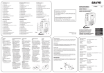
DIGITAL VIDEO RECORDER
IDVR-2300L/2304L
Operation Manual (Rev.1.0)
(I NFORMATION MAY CHANGE WITHOUT NOTICE )
Physical Unit
1
System Install 4
System Setup 7
Playback Function 17
Back Up
18
PC Viewer
20
FCC NOTICE
This device has been tested and found to comply with the limits for a Class A digital
Device, pursuant to Part 15 of the FCC Rules. These limits are designed to provide
Reasonable protection against harmful interference in a commercial, industrial or
business environment can generate, use and radiate Radio frequency energy and,
if not installed and used in accordance with the instruction, may cause harmful
interference to radio communications. However, there is no guarantee that
interference will not Occur in a particular installation.
If this equipment does cause harmful interference to radio or television reception,
which can be determined by turning the equipment off and on, the user is
encouraged to try to correct the interference by one or more of the following
measures:
‧Reorient or relocate the receiving antenna.
‧Increase the separation between the equipment and receiver.
‧Connect the equipment into an outlet on a circuit different from
that to which the receiver is connected.
‧Consult the dealer or an experienced radio/TV technician for help.
This device complies with Part 15 of the FCC Rules. Operation is subject to
the following two conditions:
(1) this device may not cause harmful interference, and
(2) this device must accept any interference received,
including interference that may cause undesired operation.
CAUTION ON MODIFICATIONS
To comply with the limits for the Class A digital device, pursuant to
Part 15 of the FCC Rules,this device must be installed in computer
equipment certified to comply with the Class A limits. All cables used
to connect the computer and peripherals must be shielded and grounded.
Operation with non-certified computers or non-shielded cables may
result in interference to radio or television reception.
Any changes or modifications not expressly approved by the grantee
of this device could void the user's authority to operate the equipment.
CE NOTICE
This is a Class A product.
DISCLAIMER
No warranty or representation, either expressed or implied, is made with
respect to the contents of this documentation, its quality, performance,
merchantability, or fitness for a particular purpose. Information presented
in this documentation has been carefully checked for reliability; however,
no responsibility is assumed for inaccuracies.
The information contained in this documentation is subject to change
without notice.
In no event will interVision be liable for direct, indirect, special, incidental,
or consequential damages arising out of the use or inability to use this
product or documentation, even if advised of the possibility of such damages.
CAUTION
TO REDUCE THE RISK OF ELECTRICAL SHOCK, DO NOT OPEN COVERS.
NO USE SERVICEABLE PARTS INSIDE. REFER SERVICING TO QUALIFIED
SERVICE PERSONNEL.
CAUTION
THE LIGHTING FLASH WITH AN ARROWHEAD SYMBOL WITHIN AN
EQUILATERAL TRIANGLE IS INTENDED TO ALERT THE USER TO THE
PRESENCE OF UNINSULATED “ DANGEROUS VOLTAGE” WITHIN THE
PRODUCT’S ENCLOSURE THAT MAY BE OF SUFFICIENT MAGNITUDE
TO CONSTITUTE A RISK OF ELECTRIC SHOCK TO PERSONS.
CAUTION
THE EXCLAMATION POINT WITHIN AN EQUILATERAL TRIANGLE IS
INTENDED TO ALERT THE USER TO PRESENCE OF IMPORTANT
OPERATING AND MAINTENANCE (SERVICING) INSTRUCTIONS
IN THE LITERATURE ACCOMPANYING THE APPLIANCE.
NOTICE:
THE SPECIFICATIONS CAN BE CHANGED OR IMPROVED W/O NOTICE.
WARNING
TO PREVENT FIRE OR SHOCK HAZARD, DO NOT EXPOSE UNITS NOT SPECIFICALLY DESIGNED
FOR OUTDOOR USE TO RAIN OR MOISTURE.
ATTENTION
INSTALLATION SHOULD BE PERFORMED BY QUALIFIED SERVICE PERSONNEL ONLY
NOTICE
POWER DISCONNECT. UNIT WITH OR WITHOUT ON-OFF SWITCHES HAVE POWER SUPPLIED TO
THE UNIT WHENEVER THE POWER CORD IS INSERTED INTO THE POWER SOURCE; HOWEVER,
THE UNIT IS OPERATIONAL ONLY WHEN THE ON-OFF SWITCH IS IN THE ON POSITION.
THE POWER CORD IS THE MAIN POWER DISCONNECT FOR ALL UNITES.
NOTICE
Please do not open the unit. There's no any parts has to be fixed by end user.
For any problems on the unit, please contact your dealer.
This manual is published on the time of the product has been made.
The manufacture has the right to change or upgrade the product without
any announcement. All the spec of product is basis on the product sold by time.
About This Manual
Before installing stand-alone DVR, be sure to thoroughly review and follow
the instructions in this User's Manual. Pay particular attention to the parts
that are marked NOTICE.Also, when connecting with external application,
first turn the power OFF and follow manual instruction for appropriate installation.
Before Reading This Manual
1. This document is intended for both the administrator and users of stand-alone
DVR model.
2. This manual contains information for configuring, managing and using
stand-alone DVR model.
3. Be sure to read through this manual before using this stand-alone DVR model.
4. To prevent fie or electrical shock, do not expose the product to heat or moisture.
5. Check electricity at the place you want to install the DVR unit if it is stable and
meets our electricity requirements. Unstable electricity will cause malfunction
of the unit or give critical damage to the unit.
6. Several chips on the main board of the DVR unit and hard disk drive inside
the unit generate heat, and it must be properly discharged. Do not put any
objects near or on top of the unit.
7. Put the DVR unit at well-ventilated place and do not put heat-generating
objects on the unit. When it is installed inside 19 inch mounting rack together
with other devices, please check built-in ventilation fan of the rack is properly
running.
NOTICE
Open Package:
Please be care to open the package to avoid dropping the unit. This might hurt
any parts of your body or the system will be broken.
Checking and Confirm:
1. If there's any damage happened on the shipping, please pack the unit in the
original box and return back.
2.Please check the goods shipped inside the package (as below). If there's any
lose, please contact your dealer.
Standard Goods with one package:
a. DVR main system *1
b. 100~240 Power Cord *1
c. DC 12V 3A Power Supply *1
d. User's Manual *1
f. Hard Disk Screws *4
3. Please keep the packing box as it is made to protect the unit in case if the
unit needs to be returned for any reason.
Working Environment:
Please do not set the unit in any case with no air circulation as the unit might
be dead on heat.
Remove Hard Disk Box:
Please turn off the system first while take out the Hard Disk Box.
TABLE OF
1. INTRODUCTION ..................................1
2. Physical Unit
2 -1 Front Panel ..............................1
2 -2 Back Panel ..............................2
2 -3 Remote Control ...........................3
3. Getting Start .....................................4
4. System Install
4 -1
4 -2
4 -3
4 -4
Monitor Connection .......................4
Camera Connection .......................5
HDD Setup ..............................5
Power Connection ........................5
5. Screen Introduction ................................6
6. System Setup ....................................7
6-1
6-2
6-3
6-4
6-5
6-6
6-7
6-8
6-9
Camera ..................................7
Record ..................................8
Motion Detection ...........................10
Screen .................................10
Audio ...................................11
System ..................................11
Search ..................................15
Language ................................16
Exit .....................................16
7. Playback Function .................................17
8. Backup .........................................18
9 . PC Viewe .......................................2 0
1. INTRODUCTION
1. Support true duplex functionality (Simultaneous
playback, record and USB media back-up)
2. Support 50-field recording frame rate
3. Host USB (avg. 300 KB/sec) drive
4. User flexible and high-quality audio (8/16/20 KHz)
interface
5. Support PS/2 USB type mouse
6. Support USB upgrade
7. Support (BNC) to connect 1~4 Cameras
2. Physical Unit
2-1 Front Panel
Power
HDD Indicator
Remote Receiver(OPTION)
Mouse
Flash Disk
PS/2 Mouse Connection
USB Storage
1
1
1
2-2 Back Panel
AUDIO OUT
AUDIO IN
MONITOR
Video Output(BNC)
VIDEO IN
CH1
~
VGA
DC-IN.12V.
AUDIO
IN/OUT
Ch4
Video Input(BNC)
VGA Output(Option)
Power Supply
(Adaptor DC12V/5A)
Audio Input/Otput RCA
2-3 Remote Control(Optional)
Digital Video Recorder
CHANNEL SELECTION
MENU
1
2
3
4
5
6
7
8
9
MENU
SEQ
REC
ENTER
9S
ENTER
4S
FUNCTION KEY
PLAY
STOP
SEQUENCE
RECORD
SCREEN SPLIT
PAUSE
UP
F.F
REW
UP
DOWN
DOWN
3
3.GETTING STARTED
Install a hard drive into your DVR
Connect DVR to monitor
Connect cameras (up to 4) to DVR
Plug the power cord into power jack on the wall
Turn on the power switch on the back of the DVR
Start TV Monitoring and Recording
… Make sure that a hard drive and camera(s) are properly installed
… If the power is turned off while recording (i.e. A power failure),
the DVR will enter”Power Recovery” mode at start up,
detect that it has been shut down,
and then reinitiate the recording process.
4. SYSTEM INSTALL
4-1Monitor Connection
[ C o n n e c t moni t o r w ith VI D E O O UT po r t o n DV R ]
MONITOR
["VIDEO IN” port on Monitor]
[”VIDEO OUT” port on DVR]
Connect "VIDEO IN" of the monitor to "VIDEO OUT" of
the DVR system.
The DVR supports BNC output
1. BNC Output
Connect the DVR “VIDEO OUTPUT” to camera(s)
“VIDEO INPUT” then see the recording screen.
4
4- 2 Camera Connection
Connect between "CHANNEL IN" of your DVR and
" VIDEO OUT"of camera with video cable and plug in
the camera’s power adapter.
“VIDEO OUT” on CAMERA
AUDIO OUT
AUDIO IN
VIDEO IN: Also can use VIDEO BALUN to connect DVR
with internet cable plug
4-3 HDD SETUP
Please use SATA HDD.
4-4 Power Connection
Connect a DVR power adapter to the adapter jack at the rear panel
of DVR unit. And turn the power switch on. It will boot up the system.
If you install a new HDD, it will ask for HDD formatting before a system
starts to run. Choose format option using”SELECT” button.
Below is the information of input/ output voltage for the power adapter.
*Input : AC 100-240V,50/60Hz,1.5A
*Output : DC + 12V == 3A
5
5.Screen Introduction
Ch1
Ch2
Ch3
Ch4
0%
2005/08/01 11:00:25
Ch1= First Camera
Ch2= Second Camera
Ch3= Third Camera
Ch4= Forth Camera
= Motion Detecting On
= Video Loss
= Recording
= Squence On
= Vidio On
= Writing to HDD, % is the HDD recording space
6
6. System Setup
Choose the “MENU” after turn on the DVR power.
Setup
Camera
Record
Motion Detection
Screen
Audio
System
Search
Language
Exit
Chinese
0% 2005/08/01 11:00:25
* Using button "
,
" to choose the language
On the DVR front panel or remote control,press "
Press “
“ can go to each sub menu.
To go back to the previous menu, press”
panel or remote control.
,
" can move the cursor up or down,
” button on the front
6-1 Camera Setup
Camera
Channel
Camera Name
Display
Brightness
Contrast
Color
Saturation
<
1>
Ch1
ON
0% 2005/08/01 11:00:25
Press"
" enter the camera video
Channel : Press “
”, “
”, OR”
” to select (1~4)
Camera Name: Change camera name.
Display : Switch on/off the camera(s) picture. When the channel is off, it will be black and show
Brightness:Select brightness of the channel
8
Contrast:Select
the contrast of the channel
Color:Select the color of the channel
Hue:Select the HUE of the channel
Press”
” or “
” to setup
The original setup is 5, can change it from 1~10
77
.
6-2 Record
Record
Record Speed
Record Quality
Event Rec Duration
Record Schedule
< Normal>
10
Press
Press
Press
,
,
to exit
to move the cursor
,
to setup
0% 2005/08/01 11:00:25
RECORD SPEED: It can be changed the frame numbers
RECORD QUALITY: Press”
” to chose HIGH/NORMAL/LOW
Event Rec Duration: You can adjust it depending on your need.
(Act time from 5~30)
RECORD SCHEDULE: It can set up the time of recording.
* If you want to stop recording, please set up the record
schedule.
6-2-1 Record Speed
RECORD SPEED
Channel -1
Channel -2
Channel -3
Channel -4
15
15
15
15
TOTAL USED FRAME =60(60)
0% 2005/08/01 11:00:25
Press
,
decrease the frame
to choose the channel,press
to increase the frame.
to
Totally are 50 frames, the most frame of each channel are 30pcs,
you can depend on your need to change the numbers.
TOTAL USED FRAME: It will show how many frames you chose in 50 pcs.
* Same adjust way for real time and motion record.
8
6-2-2 RECORD SCHEDULE
Record Schedule
0 0 0 0 0 1 1 1 1 1 2 2
0 2 4 6 8 0 2 4 6 8 0 2
No Record
Time Record
Motion+ Sensor Record
Time+ Motion+ Sensor Record
0% 2005/08/01 11:00:25
> ,can choose
Press<
No record : Only if pressing
or the DVR is set on Auto Record,
the DVR will record. When recording, you can press
at anytime to stop record. For update the firmware, DVR
should be in this mode and stop recording.
Time Record:In this mode,you don’t need to press
DVR will
record automatically. Once it is on recording, DVR
won’t stop recording unless switch to No Record
mode. Time Record mode is suggested to avoid
recording loss.
Motion+Sensor Record:When individual camera is on,DVR
will only record while motion or sensor alarm is
triggered. It can save the HDD space.
Time+Motion+ Sensor Record : DVR is on recording.When
motion or sensor alarm is triggered,it will
stop recording and switch to motion or sensor record.
* Record Schedule set on 24 hours basicly
Press
Press
Press
Press
、
to move the cursor
to set
to set all
to exit
99
6-3 Motion Detection
MOTION DETECTION
Channel
Sensitivity
Motion Area
Press
Press
Press
1
4
,
to move the cursor
,
to setup
,
to exit
0% 2005/08/01 11:00:25
Channel : Press “
Sensitivity : Press”
” to setup
”,”
” or “
” to setup
Motion Area : Press”
”,”
” to move the cursor
up and down. Press “
“,”
“
to move the cursor right and left.
Setup : Select motion area first.
Move the cursor from left-top corner and press “
to right-bottom corner then press”
”.
When motion alarm is on,it will show
and
“
for recording.
6-4 Screen
Screen
Border
Video Adjustment
720 Video Out
On
Off
Press
Press
Press
,
,
to exit
to move the cursor
,
to setup
0% 2005/08/01 11:00:25
BORDER LINE:Chose ON/OFF
VIDEO ADJUSTMENT: Press
10
to adjust the screen
6-5 Audio
Audio
Record
Mute
Input Volume
Output Volume
On
Off
Press
Press
Press
,
,
to exit
to move the cursor
,
to setup
0% 2005/08/01 11:00:25
Record : Press”
Mute : Press”
” to select On/Off
” to select On/Off
Input Volume : Press”
” to adjust. From 0~10
Output Volume : Press”
” to adjust. From 0~10
6-6 System
System
Hard Disk Setup
Password Change
Time Set
Even List
F/W Upgrade
DVR Setup
9
System
Hard Disk Setup
Password Change
Time Set
Even List
Network
F/W Upgrade
Load Active-x Control
Sequence Time Set
Press
Press
Press
,
,
to exit
to move the cursor
,
to setup
11
6-6-1 HDD Setup
Hard Disk Setup
Overwrite Enabled
Format HDD
Yes
TOTAL:155904MB
USED:155904MB 100%
DISK0:155904MB Maxtor 6L160p0
Overwwrite Enabled:
If you choose YES, recording
continues and overwrites previous
recording when HDD space is full.
If you choose NO, the recording
stops when HDD is full.
TOTAL:HDD Capacity.
USED:Size of been record.
Hard Disk Setup
Overwrite Enabled
Format HDD
YES
Format Master HDD
To format HDD, you must stop recording
and enter the password first, then format.
TOTAL:155904MB
USED:155904MB 100%
DISKO:155904MB Maxtor 6L160p0
( YOU MUST STOP RECORDING)
Press
Press
Press
,
,
to exit
to move the cursor
,
to setup
6-6-2 Password Change
Default Password is 111111
Password Change : Enter “Password Change”
Current Password : Input the old password
New Password : Input the new password
Current Password : Confirm the new password
Passwordn Change
Current Password
-----1 2 3 4 5 6 7 8 9 0 - =←
qwert yu i op[ ]
a s d f g h j k l ; Shift
z x c v b nm , . / Enter
Password Change Successful
* If you lost your password, please ask your agent.
Press
Press
Press
12
,
,
to exit
to move the cursor
,
to setup
6-6-3 Time Set
Time Set
Time Zone
( GMT+08:00)
[Taipei
]
Time Set 2007/06/02 15:40:00
Daylight Saving Time
Apply
According the time zone to do the time set
Enter the Time Set then can change the time, date and year.
Press
Press
Press
,
,
to exit
to move the cursor
,
to setup
* Once you finish time setting, move the cursor to Apply then press
Enter.
If you have NTP server, please key in the server IP address,
the time will be the same with NTP server.
6-6-4 Even Listt
Even Select
068 07/06/08 20:39:05 REC START
067 07/06/08 20:39:04 POWER ON
066 07/06/08 20:38:47 POWER OFF
065 07/06/08 12:04:56 REC START
064 07/06/08 12:02:30 REC STOP
063 07/06/07 13:48:56 REC START
062 07/06/07 13:48:56 POWER ON
061 07/06/07 13:48:39 POWER OFF
060 07/06/07 10:41:56 REC START
059 07/06/07 10:41:56 POWER ON
System will record when the power switch on/off, record start/stop,
and alarm on ...etc.
Press
Press
Press
,
,
to exit
to move the cursor
,
to setup
13
13
6-6-6 F/W Upgrade
F/W Upgrade
The DVR can make the F/W Upgrade by
USB(HOST/Flashdrive),please ask
your manufacturer.
Searching Firmware...
Plug the USB(HOST/Flashdrive) into
the USB Link, and press”ENTER” in
the upgrade list.Then press”PLAY”,
it will copy the file into the DVR.
.
DVR restart automatically after
upgrade completely.
F/W Upgrade
*When upgrade the F/W,
Stop DVR record first.
Current Ver : 2.19
New
Ver : 2.19
Press [PLAY] UPLOAD,[STOP]CANCEL
*HDD will format after F/W upgrading,
please make sure there is no important
files in the HDD.
*It is not 100% guaranteed with using
USB upgrading the F/W, please beware
of using carefully. If fail the upgrading,
please contact your manufactory.
F/W Upgrade
Firmware Reading Loading...
Press
Press
Press
14
,
,
to exit
to move the cursor
,
to setup
6-6-8 DVR Setting
DVR Setup
Sequence Duration
Auto Record Setup
Menu Password
Stop Password
Camera Name Hide
LOSS ALARM
Alarm Duration
1
off
off
off
off
off
5
0% 2005/08/01 11:00:25
Sequence Duration:Set sequence duration(1~9 sec),press
sequence on,it will show
.
Auto record :Can be OFF or set the sequence duration 1~9
mins. When record schedule is set on no record,
if you didn’t press the record key, it’s easy forget
to record. If you set on Auto Record, it will record
automatically on the set time.
Menu Password: Can be On or Off.When it is on,you have to
key passwords when enter Menu.
Stop Password: Can be On or Off. When schedule record
is set on OFF,you have to enter the
password to stop the record to avoid
recording loss.
Camera Name Hide: Can be On or Off.
Loss Alarm:Can be On or Off. When it is on, it will alarm when
loss video.
Alarm Duration:Set alarm duration.
6-7 Search
Time Search
In the live screen, press”SELECT”
to search the time.Press”FASTWARD”
&”BACKWARD” to adjust the time.
Start 2007/06/09 17:18:26
End 2007/06/12 16:03:55
2007/06/09
Search
16:36:40
Press
Press
Press
,
,
to exit
to move the cursor
,
to setup
15
15
17
6-8 Language
Language
English
German
Italian
Chinese
Press
Press
Press
,
,
to exit
to move the cursor
,
to setup
6-9 Exit
Exit
Exit & Save Changes
Exit & Discard Changes
Load Setup Default
Please save then exit, if have any changes.
If want to back to the original setup, please move the cursor to
the Load setup Default, press”
” and input the password
then it back to the original setup.
16
7. Playback Function
7-1.R ecord
There are 3 types of DVR recording as below:
1. Setup the record schedule at real time.
It will start record when switch on the DVR power,
but it can’t stop when it’s recording.
2. Do not setup the record schedule.
Press “RECORD” to record and press “RECORD” again
or “STOP” to stop record.
3.Setup the record as ALARM or SENSOR record.
Press “RECORD” to record real time, cancel record will
be ALARM or SENSOR record.
7-2.P layback
There are 3 ways to playback
1. Press “PLAY” to show out the”Search” list on the screen.
And chose the time that you’re going to playback.
2.Select the “Search” at “System” list, and chose the time that
you’re going to playback.
3.Select the”EVEN LIST” at “System” list, and chose the even
that you’re going to playback.
17
8. Back Up
8-1.USB HOST Back Up
( 1) . Playback operation
First: make sure starting and ending time is recorded.
Prepare the USB host to connect to the DVR to start recording at start up time.
Start
2007/06/24 17:14:15
End
2007/06/24 17:14:17
Size
2368KB
(UP) START TIME
(REC) CDR COPY
HDD Data
(DOWN) END TIME
(SELECT) USB COPY
Press”
”to ajust playback time,suggest the starting time should be
2 sec before the time you want to backup.
Press”
”to exit and press”
”to playback.
Time Search
Start
End
2007/06/09 17:18:26
2007/06/12 16:03:55
2007/06/09
16:36:40
Search
(2).Set back up file starting time
When DVR playback to the starting time of the file,
press”
”,then press “
“system will record the time and
display on the monitor.
開始
2007/06/24 17:14:15
(UP) START TIME
Press
will show
starting time
(DOWN) END TIME
(SELECT) USB COPY
Data
18
(3).Set Back Up file ending time
After set the starting time,press”
”fastfoward to the end of back up file,
press ”
” back to normal play,when it is on the back up file ending time,
press ”
” ,system will record the time and the size of the back up file and
show on the monitor.
St a r t
End
Si z e
2 0 0 7 / 0 6 / 2 4 17:14:15
2 0 0 7 / 0 6 / 2 4 17:14:17
2368KB
Size of the Data
(U P ) ST A R T TI M E
(R E C ) CD R CO P Y
(DOWN) END TIME
(SELECT) USB COPY
Prss"
”to see the
backup end time.
(4). Flash drive setup information via USB
After confirming the flash drive capacity connects via USB port and press”
The unit automatically sets up the required procedures.
”.
Backup To USB
Start
2007/06/24 17:14:15
End
2007/06/24 17:14:17
Disk Available
508156KB
Copy Size
2368KB
File Name
01010058.VVF
Writing To USB
2368KB
Time To Remain
9 SECS
COMPLETE
Backup file name
Writing to USB displays hard drive size
Backup To USB
Start
2007/06/24 17:14:15
End
2007/06/24 17:14:17
Disk Available
508156KB
Copy Size
2368KB
File Name
01010058.VVF
Writing To USB
2368KB
Time To Remain
9 SECS
COMPLETE
Elapsed time.
Upon successful completion of setup, the Copy Frames to USB
screen will be displayed. Press “
” to return to normal view.
19
9. Instructions of PC VIEWER
Minimum System Requirements
Windows 2000/ XP Requirements
Direct X
7.0 Requirements
CPU
1GHz Requirements
RAM
256Mbytes Requirements
(1)Setup
Play the CD and chose the “4ch PC VIEWER”
(2).Open:
23
20
(3). Function
:Open backup file and play.
:Skip Back x 2,x4,x8,x16,x32,x64,x128,x256,x512,x1024…
:Review
:S tep R eview
:Pause
:S tep F orward
:Play
:Fast F orward x2,x4,x8,x 1 6 , x 3 2 , x 64,x128,x2 5 6 , x 5 1 2 , x1024….
21
:Picture c atch u p .
(Default C :\VxCap ture\ )
:Switch s ingle c hannel.
:Switch t o Q uad s creen.
(4). Transfer to AVI file
※Please transfer the file to VVF first.
Than transfer to AVI file.
AVI file size is more bigger then VVF file.
22
Click mouse right key to transfer AVI file.
To call AVI file. System transfer automatically.
User select channel 1~4.
User can change the save place.
Compress quality:
User can choose AVI format.
23
About
USB setup time procedure
HDD TIME(S)
DATE SIZE KB
Backup time
30sec.
22016KB
85 sec
90sec.
68288KB
260 sec
180sec.
132160KB
504 sec
300sec.
215744KB
794 sec
600sec.
449664KB
1711 sec
※The form only for reference
24
Select compress format than press Enter.
Transfer information.
Screen shows each camera time.
PC viewer will always on top of screen.
Use full screen to operate PC viewer.
Change resolution 640x448 or 640x554.
25
For more information please contact your sales agent.
Sales Agent:
2 0 0 6 0 4 1 9 0 0 1
26