1
TDFM-136
VHF/FM DIGITAL AIRBORNE TRANSCEIVER
OPERATOR'S GUIDE
Til Document No.
Rev. C
99RE266
(For Software Release: 2.0.0)
APR 2004
T ab l e of Co n t e nt s
SECTION 1 - Introduction............................................................................................................................ 1
1.1 Command Methodology.................................................................................................................... 1
SECTION 2 - Operator Commands............................................................................................................. 5
2.1 Operator Level 1 Commands............................................................................................................ 5
L1-1. Select the Operating Memory for the Main Channel (MN)........................................................5
L1-2. Increase Display Brightness..................................................................................................... 6
L1-3. Edit Channel Operating Mode (MN/GD)................................................................................... 6
L1-4. Scroll Backwards through Available Memories........................................................................ 7
L1-5. Start/Stop Scan (MN)............................................................................................................... 7
L1-6. Scroll Forward through Available Memories (MN).................................................................... 8
L1-7. Edit Channel Operating Frequency (MN/GD)........................................................................... 9
L1-8. Decrease Display Brightness................................................................................................... 9
L1-9. Edit Channel Squelch Mode (MN/GD)....................................................................................10
L1-0. Command Level Up................................................................................................................ 15
2.2 Operator Level 2 Commands.......................................................................................................... 16
L2-1. Create/Edit All Channel Information (MN/GD restricted)....................................................... 16
L2-2. Copy Guard to Main .............................................................................................................. 18
L2-3. Lock Keypad .......................................................................................................................... 19
L2-4. Not Used.................................................................................................................................19
ii
L2-5.
L2-6.
L2-7.
L2-8.
L2-9.
L2-0.
L2–*.
L2–#.
Edit Scan List & Enable/Disable Scan (MN)........................................................................... 19
Edit Channel Text Description (MN/GD).................................................................................21
Create Shadow Channel........................................................................................................ 22
Copy Main to Guard .............................................................................................................. 24
Edit Unit ID Value (MN/GD).................................................................................................... 24
Command Level Up ............................................................................................................... 25
Command Level Down........................................................................................................... 25
Not Used................................................................................................................................ 25
2.3 Operator Level 3 Commands.......................................................................................................... 26
L3-1. Select Boot Channel............................................................................................................... 26
L3-2. Unused................................................................................................................................... 27
L3-3. Select Hex/Decimal Edit Mode............................................................................................... 27
L3-4. Display Software Release and Version Information.............................................................. 28
L3-5. Edit Scan Parameters (MN)....................................................................................................28
L3-6. Configure the PTT Timer........................................................................................................ 31
L3-7. Side tone Audio Level Adjust..................................................................................................32
L3-8. PC Data Upload/Download ....................................................................................................33
L3-9. Display Channel Squelch Parameters.................................................................................... 33
L3-0. Command Level Up ............................................................................................................... 34
L3-*. Command Level Down............................................................................................................ 34
L3-#. Unused .................................................................................................................................. 34
SECTION 3 - Appendix A...........................................................................................................................35
iii
SECTION 1 - Introduction
This section provides the user with a reference of the keypad accessible programming features of the
Technisonic TDFM-136 VHF FM Digital Transceiver.
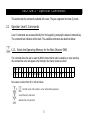
1.1
Command Methodology
This section describes how the TDFM-136 command structure is organized.
Command Levels
In order to accommodate the necessary commands, the commands have been divided into
different levels, each command level has up to 12 commands numbered 0-9, # and *; the zero
(0), and the ESC (*) key are functions for every level, they allow the user to move between levels
as follows:
step up through command levels
step down through command levels
When stepping through command levels, the indicated level is shown in subscript in the 4th character
position on the lower line of the display. Note that this display position is left blank for the default level
(level1). Table 1 shows the command levels and the associated display character.
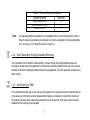
1
Table 1. Command Levels
Level
Display
Operator L1
Operator L2
Operator L3
blank
‘2’
‘3’
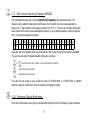
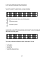
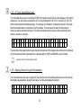
The Figure below shows the front panel display for different Command levels.
0 0 1
G D 2
M a i
3
n
G u a r
d 2
D 1 3 6 .
0 0 0 0 R g
w 1 7 4 .
0 0 0 0 R t
Command Types
There are two basic command types: Inherent and Edit. An Inherent command is one that requires no
additional input from the user, such as the ‘memory brightness’ or ‘scroll memory’ commands. An Edit
command requires further input from the user.
Command Scope
Most, but not all, edit commands can affect either the Main or the Guard Channel. The channel to be edited
depends on the position of the MN/GD and the G1/G2 front panel switches. In this manual, the scope of the
command is given on the command title line as follows:
2
(MN/GD)
(MN)
Blank
for a command that is valid in both Main and Guard,
for a command that is valid for Main only
for a command that is not subject to channel restrictions.
Command Conventions
After selecting the command, the system expects further input from the user. All edit commands may be
terminated in the same way:
accept the entry and return
abandon the entry and exit
The commands that allow the user to choose an option from a list, will always use the up/down arrows:
(key2 and key8) to step UP and DOWN – respectively - through the available choices. In addition, the key
that was used to enter the function can be used to step UP through the available choices.
Example:
the user selects the L1-3 (Op Mode) command, once the user has selected the command they
can press
and
, to step up, or
to step down through the choices. The
advantage of the 'entry key' step method is that the user does not have to move their finger to
a different key to make the choice once the command has been selected.
3
Command Reference
Table 2 below shows the commands divided into command levels: one, two, and three.
Table 2. Command Level Reference
Key
1
2
3
4
5
6
7
8
9
0
#
*
Level 1
CHAN
up
MODE
back
SCAN
fwd
FREQ
down
SQL
PROG
ENTER
ESC
NOTE:
Select Main Memory
Display – Brighter
Edit Mode
Scroll Memory Down
Scan ON/OFF
Scroll Memory Up
Edit Frequency
Display – Dimmer
Edit Squelch
Go to next level
n/u
n/u
Level 2
Program New Memory
Copy Guard to Main
Lock Keypad
n/u
Edit Scan
Edit Description
Create Shadow Channel
Copy Main to Guard
Set Unit ID
Go to next level
n/u
Go to Previous level
n/u indicates command keys that are not currently implemented.
4
Level 3
Select Boot Memory
n/u
Select HEX/Decimal Edit
Display Software rev
Set Scan Parameters
Set PTT Timer
Set Side-tone Audio
PC Communications
Display Squelch Values
n/u
n/u
Go to Previous level
SECTION 2 - Operator Commands
This section lists the commands available to the user, They are organized into three (3) levels.
2.1
Operator Level 1 Commands
Level 1 commands are accessed directly from the keypad by pressing the desired command key.
The command level indicator will be blank. The available commands are described below:
L1-1. Select the Operating Memory for the Main Channel (MN)
This command allows the user to select the MAIN channel that the radio is operating on. Upon selecting
this command the cursor will appear at the first digit in the channel number as shown:
0 0 0
E n t e
r
N u m b e
r
(
0 -
9 ,
Now, select a number from 001 to 230 as follows:
to
decimal mode: enter number, cursor automatically advances
accept the entry and return
abandon the entry and exit
5
# *
)
Note:
If the channel number selected is out of range then the cursor will remain until the user enters a
valid number. If there is no information programmed for the channel, the editor will return to the
previously displayed channel.
L1-2. Increase Display Brightness
Press and hold the up arrow (2) key to increase the brightness of the LED display, it stops at maximum.
L1-3. Edit Channel Operating Mode (MN/GD)
This command will edit the Operating Mode of the selected channel, the available modes are shown in table
3. Upon selecting this command the cursor will appear at the MODE position:
0 0 1
E d i t
M a i
M o
n
d e
(
D 1 3 6 .
↑ ↓ 3 , # * )
You may now edit the Operating Mode as follows:
step through the available entries
accept the entry and return
abandon the entry and exit
6
0 0 0 0 R g
Table 3 Channel Operating Modes
Operating Mode
Indicator
Analog Wide (25 kHz)
Analog Narrow (12.5 kHz)
Digital (12.5 kHz)
Note:
>w=
>n=
>D=
If an Operating Mode is selected that is incompatible with the current Squelch Mode, then the
Squelch mode will automatically be changed to one that is acceptable for that Operating Mode
(ie >x' for analog, 'm' for Digital Rx and 'g' for Digital Tx).
L1-4. Scroll Backwards through Available Memories
This command will scroll the Main Channel BACK, or down, through the programmed memories until
reaching the lowest memory programmed, it will then wrap around and restart from the top. Once the user
releases the button the displayed characteristics will be programmed. The scroll speed will increase as the
button is held.
L1-5. Start/Stop Scan (MN)
This command allows the user to start and stop Scan operation, the system will scan the channels that are
in the same scan list that the currently displayed Main channel is a member of. Note that the channels in
the scan list must have scan enabled (see command L2-5) to be scanned. If the memory scan has been
enabled then the following screen appears:
7
0 0 1 1
G D 1 ∩
M a i
G u a
n
r d
D 1 3 6 .
n 1 5 4 .
1
0 0 0 0 R g
0 0 0 0 R t
Once scan has started the scan list digit flashes to indicate that the unit is in SCAN mode. Also note that
the key level indicator position has the lock symbol (∩, this indicates that all keypad keys are disabled
except for:
stop scan
display brightness
Front panel switch operation is modified as well: operation of MN/GD or G1/G2 will terminate scan and
restore normal operation of keys and switches. The front panel Squelch button is disabled. The HI/LO
power switch is unaffected. If you try to start scan on a channel or memory that doesn't support scan, you
will see:
0 0 1
E r r o
M a
r :
i
n
N o
n -
S c
D 1 3 6 .
a n n e d
0 0 0 0 R g
C h a n
L1-6. Scroll Forward through Available Memories (MN)
This command will scroll FORWARD, or up, through the programmed channels, scroll speed will increase
as the button is held and the scroll will wrap around and restart from the bottom. Once the user releases the
button the displayed characteristics will be programmed.
8
L1-7. Edit Channel Operating Frequency (MN/GD)
This command allows the user to edit the Operating Frequency of the selected channel. The
frequency will be edited in duplex mode: first Receive, then Transmit. Once the receive parameter is
entered, the 2nd last chartacter in the display will switch from “R” to “T”, the user can now enter the transmit
value. Note that the receive value is automatically entered, so to get simplex operation, simply accept this
entry. The edit screen appears as follows:
0 0 1
E d i t
M a
F
i
r
n
e q u e
n c
D 1 3 6 .
y
( 0 -
0 0 0 0 R g
9 , # * )
Upon start, the cursor appears at the second character in the Frequency field of the channel to be edited.
The user may now enter the desired operating frequency as follows:
to
decimal mode: enter number, cursor automatically advances
accept the entry and return
abandon the entry and exit
The editor will not accept a value outside the limits of 136.0000 MHz. to 174.0000 MHz. In addition
frequency selection is limited to 2.5 kHz increments in all Operating modes.
L1-8. Decrease Display Brightness
Press and hold the down arrow (8) key to decrease the brightness of the LED display, it stops at minimum.
9
L1-9. Edit Channel Squelch Mode (MN/GD)
This command will edit the Squelch Mode of the selected channel, and then allow the user to edit the
associated Squelch Mode Value. As with the Frequency Edit function above, the Squelch Edit is in duplex
mode, Receive followed by Transmit. The edit screen appears as follows:
0 0 1
E d i t
M a i n
S q l
M o
d e
D 1 3 6 . 0 0 0 0 R g
( ↑ ↓ 9 , # * )
Upon start, the cursor appears at the Squelch Mode indicator position of the channel to be edited. The user
may now select the desired Squelch mode from the list, as follows:
step up through available Squelch modes (see table below)
step down through available Squelch modes
accept the entry and return
abandon the entry and exit
The available options are constrained by the operating mode, that is, different Squelch Modes are available
for the analog Operating Modes (wide and narrow) than for the P25 operating mode. See table 4 below.
10
Table 4. Receive and Transmit Squelch Modes
Analog
Rx
Analog
Tx
Digital
Rx
Digital
Tx
Noise
Rx
None
Tx
TalkGroup + NAC
Rg
TalkGroup + NAC
Tg
CTCSS Tones
Rt
CTCSS Tones
Tt
NAC Only
Rn
ID Call
Ti
DCS Code
Rc
DCS Codes
Tc
Monitor
Rm
Inhibit
T-
Inhibit
T-
Once the Squelch Mode has been selected, the user will be allowed to edit the value of the selected mode.
The Squelch Modes that may be edited are: Noise, CTCSS Tones, and DCS Codes for analog operating
modes, and TalkGroup, NAC, and ID Call for digital operating mode.
L1-9.1 Edit Noise Squelch Value analog only, receive only, range 0-16
If Noise (Rx) is chosen, the prompt line will display the current value for noise squelch level and place the
cursor on the first digit, the value can be edited using the keys shown below.
0 0 5
N o i s
to
T
e
e
s
L
t
e
n
v
e
l
1 5 6 .
:
decimal mode: enter number, cursor automatically advances
accept the entry and return
abandon the entry and exit
11
0 0 0 0 R x
1 0
L1-9.2 Select CTCSS Tone analog only, receive & transmit, 42 tones (67Hz to 254.8Hz)
If CTCSS Tones are chosen, the prompt line will display the current value for that tone, the user can select
the tone using the keys shown below. Appendix A lists the available tones.
0 0 5
T e
C T C S S
s
T
t
o
n e
(
n 1 5 6 . 0 0 0 0 R t
↑ ↓ , # * ) :
6 7 . 0
step up/down through available CTCSS Tones
accept the entry and return
abandon the entry and exit
L1-9.3 Select DCS Code Scope: analog only, receive only, 83 codes (23 to 754)
If DCS Codes are chosen, the prompt line will display the current value for that code, the user can select
the code using the keys shown below. Appendix A lists the available choices.
0 0 5
T e s t
D C S
C o d e
n 1 5 6 .
(
↑ ↓ ,
step up/down through available DCS Codes
accept the entry and return
abandon the entry and exit
12
# * )
:
0 0 0 0 R c
2 3
L1-9.4 Edit Project 25 Talkgroup Value digital only, receive & transmit, range 0-65535 ($0000-$FFFF)
If the P25 TalkGroup was chosen the, the prompt line will display the current TalkGroup value, the cursor
will be on the first digit:
0 0 1
P 2 5
M a
T a
i
l
n
k G r
o
D 1 3 6 .
u p :
0 0 0 0 R g
0 0 0 1
This parameter may be edited in either HEX or in Decimal (see command L3-3). The edit keys are as
follows:
hex edit: step up/down through hex digits (0-9, A-F)
hex edit: move cursor forward / backward
to
decimal mode: enter number, cursor automatically advances
accept the entry and return
abandon the entry and exit
Note:
If P25 Talkgroup was chosen, the editor will proceed to Edit NAC upon accepting the Talkgroup
value.
13
L1-9.5 Edit Project 25 NAC Value Scope: digital only, receive and transmit, range 0-4095 ($000-$FFF)
If the P25 NAC was chosen (or after entering the P25 TalkGroup) the prompt line will display the current
NAC value, with the cursor on the first digit:
0 0 1
P 2 5
M a i n
N A C :
D 1 3 6 .
0 0 0 0 R n
0 0 1
This parameter may be edited in either HEX or in Decimal (see command L3-3). The edit keys are as
follows:
hex edit: step up/down through hex digits (0-9, A-F)
hex edit: move cursor forward / backward
to
decimal mode: enter number, cursor automatically advances
accept the entry and return
abandon the entry and exit
L1-9.6 Edit Project 25 ID Call Value - Scope: digital only, transmit only, range 0-9,999,999
If the P25 ID Call is chosen, the prompt line will display the current ID Call value. This parameter may only
be edited in decimal, as follows:
14
0 0
1
P 2 5
M a
C a
i
l
n
l
U n i
t
D 1 3 6 . 0 0 0 0 T i
# :
0 0 0 0 0 0 1
This transmit only mode allows the user to try to contact a specific radio by transmitting that radio's user ID.
If no radio has that ID then this will fail.
The keys used to edit the ID call parameter are:
to
decimal mode: enter number, cursor automatically advances
accept the entry and return
abandon the entry and exit
L1–0. Command Level Up
This key selects the next HIGHER Command Level, the Command Level is indicated by a subscript digit in
the 4th character position on the lower row of the display. See table 2-1.
Upon pressing this key, the radio will remain in the new Command Level for 5 seconds, if there is no further
user input within this time then the radio will revert to Level 1. The Direct Command Level (level 1) is the
normal operating mode for the radio and is indicated by a blank space.
L1. Not Used
15
2.2
Operator Level 2 Commands
Access the Level 2 Commands by pressing the >PROG= key from the Operator Level 1 once, the Menu
Level indicator will show a subscript >2=.
Note: the system is time limited in command levels above level 1. The system will automatically return
to level 1 if a command has not been selected in five (5) seconds!
L2–1. Create/Edit All Channel Information (MN/GD restricted)
This command allows the user to create a new memory position (for Main channel only) or to edit all the
parameters of an existing memory position (Main or Guard channels). The editor steps through the channel
parameters in sequence from left to right across the screen. The edit functions here match those used to
edit an individual parameter; in this case however selecting the ENTER key accepts the data and proceeds
to the next step, rather than returning. Only after the last step does selecting enter save the data and exit..
The ESC key will abandon the entire edit session without changing an existing channel or creating a new
one.
accept the entry and return
abandon the entry and exit
16
L2-1.1. Entering a Memory Number (refer to L1-1 for details)
When the Create/Edit All command is selected, the first step is to enter the number of the memory position
that you wish to Create or Edit. Note that if the Radio is on a Guard channel then the editor starts at the
“Edit Text” prompt (step 3 below) as the memory number and scan cannot be edited for Guard channels.
The valid range is (001 to 230)
Once a number has been entered, the system checks to see if the memory location has already been
programmed, if so, then the existing data will be loaded, if the location has NOT been previously
programmed then the default template data will be loaded. In each case the user can edit the channel
parameters in the same way as shown in the following steps.
L2-1.2. Enter a Scan Zone & Enabling/Disabling Scan (refer to L2-5 for details)
The cursor will move to the third (3rd) position on the top line, the default scan zone is shown in subscript. If
there is a bar over top of the character, this indicates that scan is disabled for this memory, if there is no
bar, then scan has been enabled. The 'PROG' key (key 0 ) toggles the scan enabled/disabled state.
L2-1.3. Enter a Text Description (refer to L2-6 for details)
After SCAN, the cursor moves to the first position in the text description field, the user may now edit the
existing test as desired. The editor allows you to select all upper and lower (A-Z, a-z) case alphabetic
characters, the numbers from zero to nine (0-9), and a selection of extra characters including the space.
L2-1.4. Enter an Operating Mode (refer to L1-3 for details)
After TEXT, the cursor is positioned on the one (1) character Operating Mode (Mode) field, this single
character represents the operation of the radio: analog wide, analog narrow, or digital.
17
L2-1.5. Enter a Frequency (refer to L1-7 for details)
The frequency parameter is a seven (7) digit decimal parameter, though the first digit is always one so the
user cannot edit that digit. The frequency parameter may be edited to any number between 136.0000 and
174.0000 in 2.5 kHz. steps. (ie 150.0025 is valid, 150.0046 is not).
This is a duplex parameter, that is, the user has a chance to edit both the receive value followed by the
transmit value. Once the receive value has been accepted, pressing 'ENTER' again will accept the same
value for transmit.
L2-1.6. Enter the Squelch Parameters (refer to L1-9 for details)
When the Create/Edit All command is selected, the first step is to enter the number of the memory position
below) as the memory number and scan cannot be edited for Guard channels.
Once the user is finished and selects ‘ENTER’ then the newly edited channel parameters are selected and
displayed for the appropriate channel. This may take a moment as the information is programmed into the
appropriate RF module at this time as well.
L2–2. Copy Guard to Main
Copy the currently displayed Guard information UP to the Main channel. This is irreversible, so be sure you
wish to do this. As a safety precaution this command is disabled from the factory.
18
L2-3. Lock Keypad
This command locks the keypad to prevent accidental change to parameters of the radio unbeknownst to
the operator. This will disable all keyboard functions (except keyboard unlock and display luminance). To
unlock the keyboard, press and hold the >ESC= key for two seconds.
Lock the keypad, display 'locked' until key release
unlock the keypad (after 2 secs), display 'unlocked' until key release
L2–4. Not Used.
L2–5. Edit Scan List & Enable/Disable Scan (MN)
This command allows the user to select which of the SCAN LISTs - if any - that the selected channel is
included in. The memory must be a member of one of the fifteen (15) scan lists that are supported. In
addition, it allows the user to select whether or not the scan is enabled for the current memory.
The cursor will move to the fourth (4th) position on the top line, the default scan list is shown in subscript. If
there is a bar over top of the character, this indicates that scan is disabled for this memory, if there is no
bar, then scan has been enabled.
19
0
1 5
—
E
d i
t
1
D e
s
Z o
c
w 1 4 1 .
n e
/
S c
a
n
(
0 0 0 0 R x
↑ ↓ 0 ,
# *
)
The user may select the scan list for the memory as follows:
step up through available scan lists
step down through available scan lists
toggle the scan enable / disabled (bar = disabled)
accept the entry and return
abandon the entry and exit
Note:
0 1 5
G D 2
If a scan list is full, it will NOT appear in the group of available scan lists. This includes the
default list. When this happens, the unit will display the next higher available list, this will stop
at list 15 and then loop back to list 1.
2
D e s
G u a
c
r
w 1 4 1 .
w 1 7 4 .
d 2
20
0 0 0 0 R x
0 0 0 0 R t
L2–6. Edit Channel Text Description (MN/GD)
This command allows the user to edit the text description for the selected channel. There are four groups of
characters that may be used; upper case (A-Z), lower case (a-z), numbers (0-9), and 16 extra characters:
{blank space ! “ # $ % & ' ( ) * + , - . / }. The user can change character groups at any time and as
many times as desired during a description edit session.
0 0 6
E d i t
D e
T
s
e
c
x
t
(
w 1 4 1 . 0 0 0 0 R x
↑ ↓ ← → 3 , # * )
A Z
The keys for the text editor operate as follows:
step through available edit groups (A-Z, a-z, 0-9, +extra characters – see tbelow)
scroll up/down through available characters
move cursor forward / backward
accept the entry and return
abandon the entry and exit
Note: for this command the up/down arrow keys are scroll enabled, that is, if you hold them you will scroll
through the character set rather than having to press each time you want to advance.
21
L2–7. Create Shadow Channel
This command allows the user to create a shadow channel, the steps are the same as for creating a regular
channel, except that the user must pick a primary channel on which to base the shadow channel first. Some
parameters are not valid for shadow channels so the user is not given the opportunity to enter or edit these.
L2-7.1. Selecting a Primary Number to Base the Shadow On
Upon selecting the Create Shadow Channel command the user is prompted to enter the primary channel
upon which the shadow channel is based, the screen displays the current memory number as a default:
0 0 6
E n t e
P
r
r
i m a r y
N u m b e
r
C h a n n e
( 0 - 9 ,
l
# *
)
Now, you must select an already existing channel from within the 001 to 230 limits as follows:
to
decimal mode: enter number, cursor automatically advances
accept the entry and return
abandon the entry and exit
Assume that the user entered a primary of '006', then:
22
L2-7.2. Selecting a Primary Number to Base the Shadow On
Next, enter the number for the shadow channel, use the keys shown below:
0 0 6
E n t e
to
S h a d o w
r
N u m b e
C h a
r
(
n n e l
0 - 9 ,
# *
)
decimal mode: enter number, cursor automatically advances
accept the entry and return
abandon the entry and exit
Assume that the user entered '061' as the desired shadow channel number. The radio will now display the
data from the chosen Primary channel.
0 6 1
E d i t
C h a
T e
n
x t
6
(
D 1 6 6 . 0 0 0 0 R g
↑ ↓ ← → 3 , # * )
A Z
The user may now edit those data fields that are valid for a shadow channel. These are:
•
•
•
Text Description
Operating Mode
Squelch Mode and associated value
23
The editor functions and keys are the same as for any of the independent editor operation, the difference,
as with Create New / Program All (L2-1), is that the ENTER key will advance to the next editor until all valid
fields have been entered, then the ENTER key accepts an exits.
Note that there are some parameters that cannot be edited:
•
•
•
Frequency is fixed to that of the Primary channel
Shadow channels cannot be scanned.
Shadow channels cannot use the Digital Squelch Mode IDcall (i).
L2–8. Copy Main to Guard
Copy the currently displayed Main information DOWN to the selected Guard channel. This is irreversible, so
be sure you wish to do this. As a safety precaution this command is disabled from the factory. (see
Command Permissions L4-2).
L2–9. Edit Unit ID Value (MN/GD)
The Unit ID is a number from 0 to 9,999,999 that is given to the RF module, this number should be unique
within the operating group of radios, but this is NOT a universally mandated number (ie the number is NOT
assigned by any P25 umbrella group, or even by the manufacturer), the user may edit this number as
desired.
24
This command allows the user to Edit the Unit ID, note that the system has two (2) unit ID's one for the
Main, and one for the Guard. The value is editable in decimal only.
to
decimal mode: enter number, cursor automatically advances
accept the entry and return
abandon the entry and exit
L2–0. Command Level Up
This key selects the next HIGHER Command Level, the Command Level is indicated by a subscript digit in
the 4th character position on the lower row of the display. See section 2.1 above.
L2–*. Command Level Down
This key selects the next LOWER Command Level, the command Level is indicated by a subscript digit in
the 4th character position on the lower row of the display. See section 2.1 above.
L2–#. Not Used.
25
2.3
Operator Level 3 Commands
Access the Level 3 Commands by pressing the >PROG= key ( 0 ) from Level 1 twice, the Menu Level
indicator will show a subscript >3=.
L3-1. Select Boot Channel
This command allows the user to select which method will be used to determine the memory that will be
used for the Main Channel when the unit is turned on. The available choices are: the last Selected channel
or the last Programmed channel .
The default is: last Selected channel.
3 B o
3
o t
S e t
O n :
B o
L
o
a
t
s
t
M e m o
S e l
r
e
The user may select the boot memory for the main channel as follows:
toggle the boot mode
accept the entry and return
abandon the entry and exit
26
y
c
t
e
d
L3-2. Unused
L3-3. Select Hex/Decimal Edit Mode
This command allows the user to select whether to edit the TalkGroup and the NAC numbers as
Hexadecimal (Hex) or as Decimal numbers. The other parameters are edited in decimal only.
The default is: Hex Edit Mode (HEX is indicated by a preceding dollar sign: $)
3 - 3
E d i t
S e
i
t
n :
H e x
H e
/
x
D e
c
e
m a
The user may select the TalkGroup and NAC Edit mode as follows:
toggle the Hex/Decimal edit mode
accept the entry and return
abandon the entry and exit
27
l
E
d i
t
L3-4. Display Software Release and Version Information
This command allows the user to see the current software release and version number for both the Main
code, and the Boot loader code. This information is displayed on the bottom row as follows:
0 0 1
M a i
M a i n
C o
n
d e
D 1 3 6 .
:
0 0 0 0 R n
2 . 0 . 0
The user may select which information is displayed as follows:
toggle the Main/boot loader code version display
exit
The number format is as follows: Release.Version.Revision
So the number: 2.0.0 reads as Release 2, Version 0, Revision 0
L3–5. Edit Scan Parameters (MN)
This command allows the user to edit the parameters that govern the SCAN operation. There are 4 (four)
parameters that may be configured: Revert Mode, Reply Timer, Monitor Timer, and Delay Timer. As with
the Create/Edit All command (L2-1), this command is sequential, allowing the user to move between
parameters using the enter key, at the last parameter, this key accepts all and exits.
28
L3-5.1. Setting the Revert Mode default: last contacted
The Revert Mode refers to whether the radio will, when keyed, transmit on the selected memory channel, or
on the last contacted memory channel. The radio will only respond on the last contacted channel for a time
determined by the Delay timer setting, once the timer times-out, then the unit always transmits on the
selected channel. The Revert Mode screen is as follows:
3 R e
5
v e
E
r
d i
t
t
M o
S c
d e
a
:
n
P
C o
a r
n t
a
a
m e
c t
t
e
e r
d
s
The user can select the revert mode as follows:
toggle the revert mode
advance to next screen
abandon the entry and exit
L3-5.2. Setting the Reply Timer Range: 0-20s, Default: 3 seconds
The next screen allows the user to set the scan Reply time. This is the time that the radio will monitor a
channel on which RF was received, after all activity on the channel has ended (Rx or Tx). If there is further
receive or transmit activity on the channel, the timer will reset, and start again once the activity has ended.
When the timer times-out the unit will resume scan. If set to zero (0), the unit will resume scan immediately
upon end of channel activity.
29
3 R e
5
p l
E
y
d i
T
t
i
S c
m e r
a
:
n
P
a
r
a
m e
t
e
r s
0 3
The user can set the Scan Reply Timer value as follows:
to
decimal mode: enter number, cursor automatically advances
advance to next screen
abandon the entry and exit
L3-5.3. Setting the Monitor Timer Range: 1-90s, Default: 10 seconds
The next screen allows the user to set the scan Monitor time, this is the time that the radio will monitor a
channel on which RF was received, before resuming scanning. Once the timer expires, the unit will break
and resume scan, if the value is set to zero (0) then the unit will monitor the signal as long as it is received.
The edit screen is as follows:
3 M o
5
n i
E
t
d i
o r
t
T
S c a
i m e
n
r :
P
a
r
a
The user can set the Scan Monitor Timer value as follows:
to
decimal mode: enter number, cursor automatically advances
advance to next screen
abandon the entry and exit
30
m e
t
e
r s
1 0
L3-5.4. Setting the Delay Timer Range: 0-15s, Default: 5 seconds
The Delay time is the time that the radio will remain monitoring a channel after receiving on that channel
has ended. If the timer is set to zero, (0), then the unit will resume scanning immediately after receive
activity ends. This is the timer that affects the Revert Mode 'Contacted'.
3 D e
5
l a
E
y
d i
T
t
i
S c
m e r
a
:
n
P
a
r
a
m e
t
e
r s
0 5
The user can set the Scan Delay Timer value as follows:
to
decimal mode: enter number, cursor automatically advances
advance to next screen
abandon the entry and exit
L3-6. Configure the PTT Timer
The PTT timer will run whenever the user holds PTT. The PTT timer duration may be set using this
command: scroll through the available selections: OFF, 30 seconds, 60 seconds and 90 seconds.
3 T i
6
m e
S e
r
t
S e
P
t
T
:
T
T i
9 0
31
m e
s e
r
c
The user can set the PTT Timer value as follows:
step up through available
step down through available
accept the entry and return
abandon the entry and exit
L3-7. Side tone Audio Level Adjust
This command allows the user to adjust the level of side tone. The screen shows the currently selected
level as shown:
3 - 7
A u d i
S e
o
t
L
e
S i
v e
d e
l :
t
o
n e
A u d i
The user may edit the side tone audio level in either Hex or Decimal as follows:
hex mode: step up/down through available hex digits (0-9, A-F)
hex mode: move cursor forward / backward
to
decimal mode: enter number, cursor automatically advances
advance to next screen
abandon the entry and exit
32
o
L3-8. PC Data Upload/Download
This command allows a user to exchange TDFM-136 channel memory files (records) between a PC and the
transceiver. The unit must be connected to a PC running Windows 95, 98 or NT 4.0 and the TiL TDP-136
Radio Communications Software package. To exchange record data the Transceiver must be in this mode,
then the communication is controlled by the PC software. The transceiver will wait for 25 seconds to
receiver a valid record before timing out. The radio will indicate which memory is being transferred, and
when the transfer is complete.
C o
R e
m m u n i
a d y
c
a
t
e
w i
t
h
P
C
The transceiver may swap memory space during the download, if this happens the activity will be displayed
on the front panel and the download will be completed after a SWAP and ERASE cycle is finished.
abandon the PC communication mode
L3-9. Display Channel Squelch Parameters
This command allows the user to quickly find out what the various Squelch parameters are for the channel,
this displays all parameters except ID Call value. The data are displayed as follows:
R x
A
:
T o n e
1 6 7 . 0
C o d e
2 3
33
T a l k G
N A C
$ 0 0 0 1 $ 2 9 3
When displaying the receive parameters, the noise squelch level appears beneath the “Rx” that starts the
line, this space is blank in the transmit parameters display:
T
x
:
T o n e
1 6 7 . 0
C o d e
2 3
T a l k G
N A C
$ 0 0 0 1 $ 2 9 3
The user can switch between displaying receive and transmit parameters as follows:
toggle the squelch parameter display Rx/Tx
exit the command
L3-0. Command Level Up
This key selects the next HIGHER Command Level, the Command Level is indicated by a subscript digit in
the 4th character position on the lower row of the display. See section 2.1 above.
L3-*. Command Level Down
This key selects the next LOWER Command Level, the command Level is indicated by a subscript digit in
the 4th character position on the lower row of the display. See section 2.1 above.
L3-#. Unused
34
SECTION 3 - Appendix A
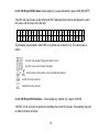
The table below shows the supported CTCSS tones.
CTCSS Tone Table
67
107.2
173.8
69.3
110.9
179.9
71.9
114.8
186.2
74.4
118.8
192.8
77
123
203.5
79.7
127.3
206.5
82.5
131.8
210.7
85.4
136.5
218.1
88.5
141.3
225.7
91.5
146.2
229.1
94.8
151.4
233.6
97.4
156.7
241.8
100
162.2
250.3
103.5
167.9
254.8
35
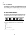
The table below shows the supported DCS codes.
DCS Codes Table
23
114
174
315
445
631
25
115
205
331
464
632
26
116
223
343
465
654
31
125
226
346
466
662
32
131
243
351
503
664
43
132
244
364
506
703
47
134
245
365
516
712
51
143
251
371
532
723
54
152
261
411
546
731
65
155
263
412
565
732
71
156
265
413
606
734
72
162
271
423
612
743
73
165
306
431
624
754
74
172
311
432
627
36