1
Setup Instructions
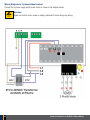
Electrical Wiring
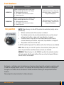
Always switch off power before doing any wiring.
Make sure that all the wiring is completed and that the motor is connected to the
control card. Recommended wire strip length should be 10mm for all
connections to the plug in terminal blocks.
DANGER
Mains
voltage
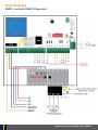
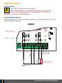
Inputs and Outputs Diagram
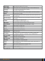
The diagram below shows the inputs and outputs available, their factory default settings, status LED’s
and the test button for each input.
415S1E
7 8
Close
Test buttons
A
B
D
C
E
Status LED's
Photo Beam
Ped Access
Common
Common
Push Button
+
-
24V DC out
150mA max
Normally Closed
User can change
Normally Open
(NO)
6
Universal Controller for 415VAC 3-Phase Motors