1
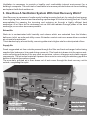
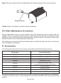
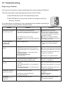
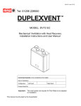
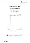
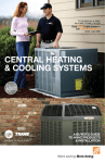
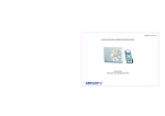
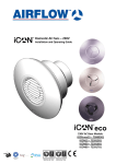
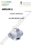
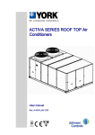
MODEL: BV400
Part No: 90000312
Mechanical Ventilation with Heat Recovery
User and Maintenance Manual
PLEASE RETAIN THESE INSTRUCTIONS WITH THE PRODUCT
Page 2 of 18
INDEX
1. Introduction................................................................................................................ 4
2. Why Ventilate?........................................................................................................... 4
3. How Does A Ventilation System With Heat Recovery Work?................................ 5
4. Components............................................................................................................... 6
5. Technical Data............................................................................................................ 6
6. Performance Curve.................................................................................................... 7
7. Sound Curve............................................................................................................... 7
8. Dimensions................................................................................................................. 8
9. Operating Instructions.............................................................................................. 9
9.1 Basic Control Settings.................................................................................. 10
9.2 Fan Speed Adjustment................................................................................. 10
9.3 Other Control Functions............................................................................... 11
10. Maintenance Instructions........................................................................................ 14
10.1 Filter Maintenance...................................................................................... 14
10.2 Heat Exchanger Maintenance.................................................................... 15
10.3 Other Maintenance Procedures................................................................. 16
11. Accessories.............................................................................................................. 16
12. Troubleshooting....................................................................................................... 17
13. Warranty.................................................................................................................... 18
Page 3 of 18
1. Introduction
Dear Customer,
Thank you for choosing a Duplexvent Mechanical Ventilation with Heat Recovery (MVHR) unit.
The balanced heat recovery ventilation unit Duplexvent BV400 has a state of the art design and
must be used according to the planning calculations and operating instructions.
Please read the information in the user manual carefully before you start using your equipment.
In this document you will find instructions for usage and maintenance which are necessary to
operate your unit properly and improve the longevity of your ventilation unit.
This manual is intended for qualified installers and users of this unit. If you have any further
questions, please contact:
Airflow Developments Limited
Aidelle House, Lancaster Road, Cressex Business Park
High Wycombe, Buckinghamshire, HP12 3QP
United Kingdom
Tel: (Int +44) (UK 0) 1494 560800
Fax: (Int +44) (UK 0) 1494 461073
E-mail: [email protected]
Visit: www.airflow.com
Please keep this manual in a place where it is accessible at all times. In case of loss of this
document please refer to the relevant product page on our website.
The manufacturer is not liable for damage caused by unprofessional installation and operation
that is not in compliance with this manual. Failure to follow these instructions may cause the loss
of product warranty.
Electrical Connection
Danger
Electric Shock
risk
Caution: Before opening the door of the unit for cleaning, filter replacement or
general maintenance always make sure that the equipment is
isolated or disconnected from the power supply.
2. Why Ventilate?
With ever increasing energy costs the need to conserve heat and power is leading to higher
levels of insulation and air tightness in residential dwellings and commercial buildings which
inevitably leads to poor indoor air quality.
In a healthy home, thousands of litres of fresh air are needed every day to replace the moist air
generated by individuals and also through cooking, washing and bathing (please refer to UK
Building Regulations, Approved Document F for guidance).
Page 4 of 18
Ventilation is necessary to provide a healthy and comfortable internal environment for a
building's occupants. The main task of ventilation is to remove polluted indoor air from a building
and replace it with fresh outdoor air.
3. How Does A Ventilation System With Heat Recovery Work?
Heat Recovery is a process of continuously heating incoming fresh air, by using the heat energy
from outgoing stale, warm air and transferring a percentage of it to the incoming fresh air. This is
accomplished by passing the incoming and outgoing air through a highly efficient heat
exchanger. At no time do the airstreams mix as the heat radiates through plates of the heat
exchanger, so no odour issues are possible.
Extract Air
Stale air is contaminated with humidity and odours which are extracted from the kitchen,
bathroom, toilet, en-suite and utility rooms. Extraction vents in wet room areas allow a constant
air volume to be extracted.
This is backed up by a boost facility, removing stale air at a higher rate for a short period of time.
Supply Air
Fresh oxygenated air from outside passes through the filter and heat exchanger before being
supplied into bedrooms, living and dining rooms etc. This fresh air is drawn into the various wetrooms collecting pollutants on its way such as moisture, odours, allergens and volatile organic
components. The air is also heated as it passes from room to room using the statutory gap at the
bottom of internal doors when closed.
The now stale, polluted air is then drawn out of wet rooms through the heat recovery unit to
outside, completing the cycle.
1
2
4
3
1
Extracted Air:
bathroom, en-suite, toilet,
utility and kitchen
2
Fresh Air from Outside:
bedroom, living-room and dining-room
5
Page 5 of 18
3
Stale Air to Outside
4
Incoming Fresh Air
5
Heat Recovery Unit
4. Components
1
2
5
3
1
Control Box
2
Extract & Supply Air Filters
3
By-pass Module
4
Heat Exchanger
5
Metal Casing
6
Extract & Supply Air Fans
4
6
5. Technical Data
EC Fan Speed settings selected on installation
(Low & High speed levels are 100% adjustable)
Typical Ventilation Settings at 100 Pa
Rated Voltage
Low
Medium
High
Boost
75 m³/hr
200 m³/hr
350 m³/hr
425 m³/hr
3.0 V
5.5 V
8.0 V
10.0 V
Maximum Air Volume (at 0 Pa)
475 m³/hr (132 l/s)
Air Volume (at 100 Pa)
425 m³/hr (118 l/s)
Thermal Efficiency (ref. SAP Appendix Q)
93%
Specific Fan Power (ref. SAP Appendix Q)
0.45 W/l/s
Power Supply
230V / 1PH / 50Hz
Maximum Power Input
180 W
Maximum Current
1.54 Amp
Filter Class (conforming to EN779)
G4 (F7 optional)
Duct Connection Ø
160 mm
Condensate Discharge Ø
22 mm
Protection Class
IP44
Operating Temperature
-10°C to +40°C
Operating Humidity
0% to 80% RH
Dimensions (W x H x D)
710 x 725 x 630 mm
Weight
41 kg
Page 6 of 18
6. Performance Curve
500
450
External Pressure (Pa)
400
350
Low Speed
Medium Speed
High Speed
Boost
300
250
200
150
100
50
0
0
50 100 150 200 250 300 350 400 450 500 550
Air Volume (m³/h)
7. Sound Curve
Octave Sound Pressure Level (dB: Overall A Scale )
dB(A)
60
50
NR50
Low Speed
Medium Speed
High Speed
Boost
40
NR40
30
NR30
NR20
20
NR0
10
63
125
250
NR10
500
1000
2000
4000
8000
Central Frequency (Cycle per Second)
Page 7 of 18
Hz
8. Dimensions
Front View
Top View
160
Rear
475
103
287
610
630
10
725
733
731
116
23
130
710
Front
Service Space
Front View
Top View
Rear
Front
min. 110 mm.
A clear space of 600mm
should be provided in
front of the unit to allow
for servicing.
Clearance for condensate drain
*All dimensions are in mm.
Page 8 of 18
9. Operating Instructions
Continuous ventilation is necessary to ensure a healthy indoor air quality and to maintain the
building fabric in good condition at all times. Even with prolonged absence of residents (ie.
holiday) it is not recommended to switch off the ventilation unit since indoor contaminants are
still being produced and entering the air, causing the air to get stuffy and a high possibility of
moisture damage due to excess humidity during the heating season.
Do not turn off the device! This is required for protection against moisture in accordance
with DIN 1946 Part 6 and Building Regulations 2010 Approved Document Part F.
The ventilation unit works properly when the flow rates are adjusted in accordance with the
above regulations to ensure optimum ventilation of the house.
Default Factory Settings
Parameters
Settings
Low Speed Supply/Extract
30% (3V)
Medium Speed Supply/Extract
55% (5.5V)
High Speed Supply/Extract
80% (8V)
Boost Speed Supply/Extract*
100% (10V)
Manual Boost Overrun*
15 min
On-demand Boost Delay*
1 min
Filter Timer*
3000 hours
Requested Indoor Temperature*
22°C
Indoor Temperature Selection*
Extract Air Temperature
-3°C
Defrost Temperature*
Defrost Cycle*
15 min
Pre-heater Temperature*
0°C
Note: The low and high speed levels can be adjusted by manual potentiometers. The medium
speed has been set in the controller's software by the manufacturer and is set as the average
value of the manually adjusted low and high speed levels.
* These values are factory set and can only be adjusted via the digital controller (BV400 SE).
Page 9 of 18
9.1 Basic Control Settings
ON/OFF: Press
for 3 seconds.
Press
to increase fan speed.
Press
to decrease fan speed.
Press
to activate the manual
“boost” function.
Child Proof Protection: To activate this function, press
and
simultaneously for 3 seconds.
When child proof protection is active, keypad is locked and buttons do
not work.
To deactivate this function press
and
for 3 seconds.
9.2 Fan Speed Adjustment
The installer is responsible for setting the required air volume rates for every room in compliance
with the Domestic Ventilation Compliance Guide 2010.
The Duplexvent BV400 unit has a 3-speed control switch which is supplied as standard. The low
and high speed levels can be adjusted by manual potentiometers for commissioning purposes.
This can be done through the control box which is located on top of the unit. The medium speed
has been set in the controller's software by the manufacturer and is set as the average value of
the manually adjusted low and high speed levels.
Page 10 of 18
9.3 Other Control Functions
Boost Function
This function is used when large amounts of exhaust and fresh air are required.
There are 2 different boost functions (Manual and On-demand):
a) The Manual Boost function is activated after pressing the “Boost” button on the
control panel
Once activated, the unit runs at the boost speed for 15 minutes.
Note: During the manual boost operation the Low, Medium and High speed LED lights
flash at the same time.
b)The On-demand Boost function is activated via volt-free or switched live contact
(see section 11) on the control board. When activated, the unit starts running at the
“High” speed until it is deactivated and goes back to the speed level that was set
before the boost operation.
Volt-free
connection
for boost
Switched live
connection
for boost
Summer Bypass
The Duplexvent BV400 unit is fitted with a bypass facility as standard. This can be used for
keeping indoor air temperature at a comfortable level.
If the house indoor air temperature is hotter than the unit temperature sensor setting (factory set
at 22°C), with the incoming air temperature lower than the indoor air temperature, the bypass
damper will open. This will tend to lower the indoor air temperature until it reaches the set
temperature level (22°C).
Page 11 of 18
At other times the unit will recover heat as long as the related dip switch in the control box is
activated.
The bypass function is activated from “dip
switch 1” in the control box on top of the
unit.
ON CEY
1 2 3 4
This can be switched off in the heating
season to have heat recovery at all times.
Frost Protection
In case of very low outside temperatures, the supply fan will reduce its speed automatically for a
short period to protect the heat exchanger from freezing. This function is active when the outdoor
air temperature falls below -3°C.
For uninterrupted air supply and extract volumes in regions with low outside temperatures
(< -5°C for more than 24 hours), an in-line electric pre-heater (see section 11) can be used in the
supply air stream from the outside to the dwelling to avoid the heat exchanger freezing. The
heater automatically switches on when the outdoor air temperature falls below 0°C.
Once installed, the pre-heater control must be activated from “dip switch 2” in the
control box on top of the unit.
Filter Maintenance Indicator
The unit is fitted with a maintenance reminder facility which has been pre-set to 4 months. When
this time interval is reached the red warning light on the control panel flashes for filter
maintenance indication. After cleaning/replacing the filters press the
and
buttons
simultaneously for 3 seconds to reset the timer.
Alternatively, optional pressure sensors (see section 11) can be used to measure the actual
pressure difference between supply and exhaust air hence monitor the filter status. The red
warning light on the control panel flashes as soon as the filters need to be maintained.
After cleaning/replacing the filters, the red warning light goes off automatically.
Page 12 of 18
Electric Post-heater
For most of the year, heat recovered from the extracted air is sufficient to warm the fresh
incoming air to the required temperature. If the heat gain from the extract air is not sufficient an
optional post-heater (see section 11) can be used to increase the indoor air temperature.
The heater is switched on/off automatically based on the extract air temperature in order to
maintain the requested indoor air temperature (factory set at 22°C).
Once installed, the post-heater control must be activated from the “dip switch 3” in
the control box on top of the unit.
Fire Switch
This volt-free contact can be used to shut down the unit in case of a fire or any other emergency.
A volt-free switch should be connected to
the corresponding socket to activate this function.
MODBUS Control / MODBUS Monitor
The MODBUS (via RS485) BMS control function helps to control the functions from a central
automation system. For more information, please contact our technical support team.
The MODBUS BMS monitoring enables the user to display the operating status of the unit and
receive fault signals (as different voltage outputs) in an unexpected failure of the unit.
This function is activated from “dip switch 4” in the control box on top of the unit.
Page 13 of 18
10. Maintenance Instructions
Heat recovery units, by their very nature, require regular maintenance. The Duplexvent BV400
has been designed to facilitate easy access to enable maintenance to be carried out.
Note: The heat exchanger will be damaged if the unit runs without the filters.
WARNING
THE FAN AND ANCILLARY CONTROL EQUIPMENT MUST BE ISOLATED
FROM THE POWER SUPPLY DURING MAINTENANCE.
Danger
Electric Shock
risk
10.1 Filter Maintenance
In the Duplexvent BV400, both supply and exhaust air streams are filtered through G4 class
course filters. The filters should always be kept in place when the ventilation unit is in operation.
To prevent the contamination of this ventilation system, to guarantee years of trouble-free
operation and ensure that clean air is supplied into your home the filters must be periodically
cleaned or replaced (depending on contamination of the outdoor air).
Step 1: Slide the service cover to the left, open it and remove the filters.
Slide the
Service Cover Left
Open the
Service Cover
Remove the Filters
Step 2: Use a vacuum cleaner to clean the dust from the air filter. If necessary, use warm water
with detergent to remove the persistent dirt. Leave the filters to dry before placing them
back in the unit.
Vacuum Cleaner
Page 14 of 18
Filter
Note: The G4 filters should be replaced once every six months or after a maximum of two
cleaning cycles. If an optional F7 filter is used please replace these filters after every
maintenance cycle (replacement filters are available on www.airflow.com, see page 15 for part
numbers).
Step 3: Place the filters in the filter slots, close the service cover and slide it to the right to secure.
10.2 Heat Exchanger Maintenance
Approximately every two years it is recommended that the heat exchanger is checked for
contamination. This time scale may vary depending on the surroundings of the property.
Inspection should be carried out when checking the filters.
WARNING
THE FAN AND ANCILLARY CONTROL EQUIPMENT MUST BE ISOLATED
FROM THE POWER SUPPLY DURING MAINTENANCE.
Danger
Electric Shock
risk
Step 1: Remove the front cover plate and the bypass module by unscrewing the screws.
Step 2: Remove the filters and pull the heat exchanger out gently using the green strap.
Caution: The fins of the heat exchanger are very thin and can easily be damaged.
Page 15 of 18
Step 3: Remove the dirt from the outside walls of the heat exchanger with a vacuum cleaner.
Vacuum Cleaner
Caution: Never use water or any other cleaning materials.
10.3 Other Maintenance Procedures
During maintenance work in autumn please check the condensate drain is secure and not
clogged. This can be tested by pouring some water into the drain pan and checking the water
coming out of the unit through the condensate drain. Clean the drain, if necessary. Also ensure
that the insulation of the condensate pipe is adequate.
Check that the unit and all wall-mount fastenings are sufficiently tight and have not become
loose. Re-tighten if necessary.
11. Accessories
The following accessories for this unit can be ordered from Airflow Developments Ltd:
Part Number
Product Description
90000336
Digital control display
90000322
G4 filter pack (2 filters)
90000323
F7 filter pack (2 filters)
90000228
Boost switch (1-way)
90000324
Electric duct heater (1 kW)
(can be used as pre-heater or post-heater)
9041570
Room humidistat
51969702
PIR Motion sensor
90000325
Built-in humidity sensor
90000326
Pressure sensors for filter monitoring
Mechanical ventilation units require good quality ducting and a high standard of installation.
To ensure the best results, we recommend the innovative AIRFLEX PRO semi-rigid ducting
system.
Page 16 of 18
12. Troubleshooting
Diagnosing a Problem
In the event of a problem, always troubleshoot the unit according to LED fault.
There are two types of warnings displayed on the control switch:
a) Red LED flashes on/off: Filter Maintenance Alert
b) Red LED flashes continuously: Failure of Components (Fans,
Sensors, Heaters)
If no indications are displayed, then troubleshoot the problem according to
the fault symptom as described in the table below:
Failure
Reason
Outdoor air coming into * Air cools down in the attic ducts
the dwelling is cold
* The heat exchanger is frozen which is why
extract air cannot heat the incoming air
* The extract fan is not running
* The extract air filter or the heat exchanger
is clogged
The unit has been
switched off
unexpectedly
* Mains voltage failure
The unit makes a lot of
noise
Gurgling noise
* Condensate trap water level is too low
* Condensate pipe is not completely in the
trap
* Condensate pipe or condensate trap is
blocked or frozen
Rumbling/Rattling noise
* Fan motor fault
Solution
Check the duct insulation
If the heat exchanger is frozen
contact your supplier/installer to
reduce the set point of the frost
protection facility
Contact your supplier/installer
Check that the filters and the heat
exchanger are clean
Consult a qualified electrician to
check mains power supply to
units.
Fill the condensate trap with water
Push the pipe deeper into the trap
Check the condensate drain and
clean it, if necessary
Contact your supplier/installer
Water leakage near the * Condensate trap is clogged or frozen
* Condensate pipe has come loose
unit
Check the condensate drain and
clean it, if necessary
Unpleasant smell near
the unit
* Condensate trap (U-bend) below the unit
is empty
* The condensate pipe is not completely in
the trap
* The condensate pipe or condensate trap
is blocked or frozen
Fill the condensate trap with water
* Air extract rates are too low
Activate the boost speed when
cooking
Replace the filters
Clean all grilles
Unpleasant cooking
smell in the house
* The filters are polluted/blocked
* The grilles are dirty
Too much
condensation in the
bathroom
* Air extract rates are too low
Page 17 of 18
Push the pipe deeper into the trap
Check the condensate drain and
clean it, if necessary
Activate the boost speed while
showering or bathing
13. Warranty
Applicable to units installed and used in the United Kingdom. Airflow guarantees the Duplexvent
BV400 units for 3 YEARS from date of purchase against faulty material or workmanship. To be
aware of the latest updates of Duplexvent BV400, please register your product at
www.airflow.com.
The warranty only covers the unit, not the re-installation of it if required.
In the event of any defective parts being found, Airflow Developments Ltd reserve the right to
repair or at our discretion replace without charge provided that the unit:
1. Has been installed and used in accordance with the fitting and wiring instructions supplied
with each unit.
2. Has not been connected to an unsuitable electrical supply.
3. Has not been subjected to misuse, neglect or damage.
4. Has not been modified or repaired by any person not authorised by Airflow Developments Ltd
5. Has been installed in accordance with latest Building Regulations and IEEE wiring
regulations.
6. Has been installed by a competent person who is qualified to do so.
Airflow Developments shall not be liable for any loss, injury or other consequential damage, in
the event of a failure of the equipment or arising from, or in connection with, the equipment
excepting only that nothing in this condition shall be construed as to exclude or restrict liability for
negligence.
All goods are sold according to Airflow Developments Limited's Standard Condition of Sale
which is available on request.
In the interest of continuous development Airflow Developments Limited continuously strive to
improve their products and reserve the right to change specifications and prices without prior
notice.
This warranty does not in any way affect any statutory or other consumer rights.
All information believed correct at time of going to press.
80000135 - Issue 1 5/13
REV01 15.07.2013
Page 18 of 18
95201074