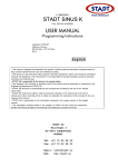
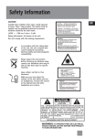
1
DSM26
DIGITAL SPEAKER PROCESSOR
www.global-9.com
User Manual
1
INPUT
A
2
B
COMP
LIMITER
IN-1
LIMITER
OVER
OVER
IN-2
OVER
OUTPUT
C
D
IN-1
LIMITER
IN-1
LIMITER
IN-2
OVER
IN-2
OVER
E
F
IN-1
LIMITER
IN-1
LIMITER
IN-2
OVER
-6
IN-2
OVER
HF
MF
-20
-40
-6
-6
HF
-6
HF
-6
HF
-6
-10
-10
MF
-10
MF
-10
MF
-10
-20
-20
LF
-20
LF
-20
LF
-40
-40
SLF
-40
SLF
-40
SLF
IN-1
PROGRAM
IN-2
STATUS
HF
REMOTE/ID
HF
-6
-10
MF
-10
MF
LF
-20
LF
-20
LF
SLF
-40
SLF
-40
SLF
POWER
MUTE
MUTE
MUTE
MUTE
MUTE
MUTE
UP
DISPLAY
DOWN
LOCK
DIGITAL SPEAKER CONTROLLER
MUTE
RECALL
/ENTER
DSM 26
MUTE
RoHS
SM-061011001-WA
Content
User manual
1.
Precaution
1
2.
Introduction
2
2.1
Audio features
2
2.2
User interface
2
2.3
Other features
2
3.
Unpacking
3
4.
AC power requirements
3
5.
Front panel control features
4
6.
Rear panel interconnect features
5
7.
Display and operation
6
7.1
Switching display mode
6
7.2
Indications and operations at lock
7
7.3
Display and operation during external control
7
7.4
To recall
7
7.5
Changing remote ID
8
Built-in signal processing
9
8.1
Input signal selecting block
9
8.2
Master channel processing block
9
8.3
Output channel processing block
9
8.
9.
System control software
11
9.1
How to get the software
11
9.2
Installing system control software
11
9.3
Connecting DEVICE to a computor
11
9.4
Application of software
12
10. Troubleshooting
20
11. Specification
21
12. Installation record
22
13. Block diagram
24
14. Dimensions
24
1> Precartions
!
User manual
Instruction:
The lightning flash with arrowhead symbol within the equilateral;
triangle is intended to alert the user to the presence of un-insulated
angerous voltage within the product's enclosure that may be of
sufficient magnitude to constitute a risk of electric shock.
The exclamation point within the equilateral triangle is intended to
alert the user to the presence of important operation an maintenance
(servicing) instructions in the literature accompanying this appliance.
Do not open the cover
Do not open the cover to avoid the risk of electric shock caused
by high voltage parts in the product. Any problems caused by
user's wrong actions are out of warranty.
Do not damage the cord
the cord Please hold the plug when pulling out or plug in the cord.
Do not pull out or touch the cord with wet hand, or it will cause the
risk of electric shock. Power supply cords should be routed so th
at they are not likely to be walked upon or pinched by items placed
on or against them. When removing the cord from a power outlet
be sure to remove it by holding the plug attachment and not by
pulling on the cord.
Avoid object and liquid entry
Take care that objects do not fall into and that liquids are not spilled
into the inside of the product.If the object or liquid enter the product,
please ask qualified personnel to check it.
Abnormal status
In the event of abnormal noise and smell, please
put off the power supply and pull out the cord,
please ask qualified personnel to check it.
Nonuse for a long time
When nonuse it for a long time, please put off
the power supply and pull out the cord to avoid
the unexpected dangers.
2> Introduction
User manual
Thank you for your purchasing of the DEVICE digital speaker processor. This processor builds on the
advanced and experienced ideas of design and marketing, the excellent audio performance and competitive
quality/price ratio make sure your interests.
This unit DEVICE, can provide the precise digital signal processing for two channel analog signal.
She has audio processor and audio management functions. It can be used to the middle/small sound
reinforcement system. And can be used as a monitor to control the working status in control center. RS-485 PC
port is provided for use with proper software system. So it is fit for the large avenue systems. The front panel
interface allows quick access to all parameter by indication functions: Full control is also available via MIDI
input and output jacks. Also indicate each channel configure information (Sound resource, subwoofer, low
frequency, middle frequency and high frequency). Numeral remote ID or current users serial number.
Setting ID or recall user's program is available by touching front panel buttons.
2.1 Audio Features
The DEVICE utilizes state of the art DSP technologies, beginning with 24bits, 64KHz delta-sigma A/D
and D/A converters, with 32 bits floating points DSP for signal processing. Digital processing includes
Gain, Polarity Invert, Parametric EQ, Shelving Filters, Delay, Crossover Functions (Butter worth/Bessel/
Linwitz,optional slope12dB~36/oct), Limiting, Signal Routing, etc. All audio inputs and outputs are precise
electrical balanced and RF protected circuit and using standard XLR connectors.
2.2 User Interface
Front panel interface:
LED dynamic indicate, Limiting function indication, Users Program configure
indication.Mute input/output indication button, Current program number and Unit
ID indication. Front panel operation/running, and Remote ID Changing
function button.
Control system software:
The computer interface uses SYSTEM SOFTWARE for Windows98 or above
version, which allows flexible user programs configuration through an USB
serial port. It can upload the user program from processor to computer,or
download the user set programs from computor to processor.
2.3 Other Features
Having 50 groups of configure programs, and many fault programs for different equipments and
application avenues, it is very convenient for user.
3> Unpacking
User manual
As a part of our system of quality control, every product is carefully inspected before leaving the factory to ensure
flawless appearance. After unpacking, please inspect for any physical damage. Save the shipping carton and all
packing materials for the future shipping and safety.In the event that damage has occurred, immediately notify your
dealer so that a written claim to cover the damages can be initiated.
4> AC power requirements
Note:
The 115V/220V switch is built in the DEVICE to avoid damage caused by wrong operation. The default set
is 220V before leaving factory. If the local voltage is 110V,please open the cover and set the switch at 110V under
disconnecting the AC power and change the 500mA fuse.. If the fuse is damaged , please replace the same type
and rating fuse.
Instruction:
The show on the switch is standard. As above diagram, the show is 220V on switch, it means the
current AC voltage is 220V.
Note:
When the local voltage is 110V, please use the 500mA delay fuse; when the local voltage is 220V,please
use the 250mA delay fuse.
5> Front panel control features
User manual
Note:
When the operation on front panel is locked(the LOCK indicator lights up ) or when connecting with PC, all
the buttons is not available.
18
1
18
INPUT
19
19
19
19
19
19 16
14
14
14
14
14
14
A
2
B
OUTPUT
C
D
E
10 12
F
LIMITER
IN-1
LIMITER
IN-1
PROGRAM
OVER
-6
HF
-6
HF
OVER
-6
IN-2
HF
-10
MF
-10
MF
-10
MF
-20
LF
-20
LF
-20
LF
-40
SLF
-40
SLF
-40
SLF
COMP
LIMITER
IN-1
LIMITER
IN-1
LIMITER
IN-1
LIMITER
IN-1
OVER
OVER
IN-2
OVER
IN-2
OVER
IN-2
OVER
IN-2
-6
-6
HF
-6
-10
-10
MF
-20
-20
LF
-40
-40
SLF
IN-2
STATUS
HF
-6
HF
REMOTE/ID
-10
MF
-10
MF
-20
LF
-20
LF
-40
SLF
-40
SLF
RECALL
/ENTER
UP
DISPLAY
DOWN
LOCK
POWER
1
1.
2.
3.
4-9.
10.
11.
12.
13.
14.
15.
16.
17.
18.
19.
MUTE
MUTE
2
3
MUTE
MUTE
MUTE
MUTE
4
9
MUTE
MUTE
15
17
11 13
Power switch
To turn the power on/off.
Input channel 1 mute button:
Press the button, the red LED on the left lights up, the input is muted. The output from Channel 1 has
not the signal output, but at the same time, input level dynamic range still shows the real input status.
Input channel 2 mute button:
Press the button, the red LED on the left lights up, the input is muted. The output from Channel 2 has
not the signal output, but at the same time, input level dynamic range still shows the real input status.
Output channel mute button:
press the button, the red LED on the left lights up, the output is muted, A-F channels have not output,
and the level dynamic range LED will be off.
Enter/recall button
When the PROGRAM indicator lights up, press the ENTER/RECALL , number display shows the
current program number, output channel LED shows the channel status. Use the UP and DOWN
buttons to find the needed program, press the ENTER button and recall the program.If you want to
cancel the recalling, press DISPLAY button under the sparkling status.
Display button
UP button
DOWN button
Output channel peak limiter indicator
Front panel lock indicator
Status indicator
Program number or ID number display
Input channel level dynamic indicator
Output channel level dynamic indicator
Remarks:
Unit of level indicator
OVER:
lights up when the wave reaches digital's full scale(the clipping level). You need to lower the level when it
lights up often.
-6,-10,-20,-40:
Indicates the level in decibels(0dBFS) on digital full scale.
6> Rear connecting featrue
2
1
BGM
F
E
ANALOG INPUT
1
D
User manual
C
B
ANALOG OUTPUT
IN
2
6
3
1. Analog input terminals(IN-1,IN-2)
Connector: XLR-3-31
1 GND 2 HOT 3 COLD
Circuit: Electronic balanced circuit
2
1
Maximum input level:+20dBu
3
BGM
SWITCH
USB
A
RS485
OUT
~ AC IN
5
7
4
5. Control interface
(standard USB)
Compatible with
USB1.1&USB2.0
2. Analog output termainals
(A.B.C.D.E.F)
Connector: XLR-3-32
1: GND, 2: HOT, 3: COLD
1
2
3
Circuit: Electronic balanced circuit
Maximum input level:+20dBu
6. Remote control input terminal
(RS-485)
3. Spare signal input terminal(BGM)
7. Remote control onput terminal
(RS-485)
Connector: 6.35 big three cores jack
1
3
2
1
3
2
1
2
3
1: GND, 2: HOT, 3: COLD
4. Pare signal switch(BGM SWITCH)
Control voltage:DC+5V-+48V
Connecting: terminal board,
tight the screw
Action status: the voltage on two terminals>
5V DC,input switch to BGM, or
the In1 and IN2 are available
1
2
3
1
2
3
GND
A+
B-
GND
A+
B-
8. Power input terminal
input voltage: Refer to 4
7> Display and operatioin
1
INPUT
A
2
User manual
B
OUTPUT
C
D
E
F
COMP
LIMITER
IN-1
LIMITER
IN-1
LIMITER
IN-1
LIMITER
IN-1
LIMITER
IN-1
LIMITER
IN-1
PROGRAM
OVER
OVER
IN-2
OVER
IN-2
OVER
IN-2
OVER
IN-2
IN-2
OVER
IN-2
STATUS
REMOTE/ID
-6
-6
HF
-6
-10
HF
-6
HF
-6
HF
OVER
-6
MF
MF
HF
-6
HF
MF
-10
MF
-10
-10
MF
-10
-10
MF
-10
-20
-20
LF
-20
LF
-20
LF
-20
LF
-20
LF
-20
LF
-40
-40
SLF
-40
SLF
-40
SLF
-40
SLF
-40
SLF
-40
SLF
RECALL
/ENTER
UP
DISPLAY
DOWN
LOCK
POWER
MUTE
MUTE
MUTE
MUTE
MUTE
MUTE
MUTE
MUTE
7.1 Switching display mode
You can change the display mode by pressing the display button in turn.
The Display mode indicator shows the current display.(Not available
during external control)
PROGRAM
STATUS
REMOTE/ID
LOCK
When PROGRAM is lit:
The number display indicates the current program number and each output channel
indicator indicates output level at that output;
When OUTPUT STATUS is lit:
The number display indicates the current program number and each output
channel indicator indicates output assignment status.
When REMOTE/ID is lit:
The number display indicators REMOTE ID number and each output channel
indicator indicates the level.
Output level indication:
A
LIMITER
IN-1
OVER
IN-2
-6
HF
-10
MF
-20
LF
-40
SLF
Indicates signal levels of each output after all signal processing.
Output level correspond to the level scale printed at the left side of the indicator.
When OVER is lit for a long time: means that the signal is too big, can lower the input
signal;
When LIMITER is lit: means the compressor is working.
Output status indications:
A
LIMITER
IN-1
OVER
IN-2
-6
HF
-10
MF
-20
LF
-40
SLF
Indicates simply which output channel is fed by which input channel and the output
frequency range based on the setting of filter cut-off frequencies.
This function helps prevent speaker from being damaged as you can make sure of
each output's status when you operate RECALL or connect an amplifier and
loudspeaker.
The print at the right side of the LED show each indication's meaning as follows:
IN-1,IN-2
Indicates which input's signal is the sound source. When both indicators
light up, it indicates monomixed signal is the sound source.
HF,MF,LF,SLF
Indicates the frequency range of each output channel:
HF : High Frequency; Lights up when frequen cies>=1KHz;
MF : Middle Frequency; Lights up when frequencies from 500Hz to 1KHz;
LF : Low Frequency. Lights up when frequencies from 100Hz to 500Hz;
SLF : Super Low Frequency; Lights up when frequencies<=100Hz.
7> Display and operatioin
User manual
7.2 Indications and operation at LOCK
To assure the use security by using an external computer(need to install control software of this processor),
you can disable RECALL and REMOTE/ID operation with the unit, and then LOCK indicator lights up.
You can operate without using an external computer to LOCK and release LOCK of the unit
To LOCK
1). Turn off the power,
2). Turn on the power with keeping pressing UP button.(Sound is not output),
3). LOCK lights up while digital transistor display normal No., move away your hand from UP ,
Auto panel operation is prohibited and come to normal working status.
To release LOCK
1). Turn off the power
2). Turn on the power with pressing DOWN button.
3). LOCK lights down while digital transistor display normal No., move away your hand from
DOWN, Auto panel operation open and come to normal working status.
7.3 Display and operation during linking to computer
You cannot use buttons on the front panel while you control with an external
computer. In this case, indicator of LOCK at DISPLAY mode indicator light up.
The number of the display indicates the current program number.
PROGRAM
STATUS
REMOTE/ID
LOCK
7.4
RECALL
: Transferring program
RECALL
/ENTER
CORUSCATE
UP
DOWN
CORUSCATE
RECALL
/ENTER
CORUSCATE
RECALL
/ENTER
RECALL of stored programs with the unit is as follows,
1). Press RECALL/ENTER button while while PROGRAM indicator lights up.
Then the currently set program number flashes and each output channel
indicator turns to flash simultaneously, meaning that it is ready for setting
output status.(Program will not be changed until step 3),
2). Select program number you to RECALL output indicating the program
arrangement information with UP and DOWN,
3). Press RECALL/ENTER button.The program number will stop flashing and
display the newest programs' Number.
Attention:
1). You can press DISPLAY button to cancel while digital transistors display, the mode will be back to the normal
status before starting RECALL,
2). Program NO. inside without save will not display,
3). RECALL operation is impossible if you press RECALL/ENTER when there is no RECALL-capable program.
Also, any stor ed pro grams w hich a re set RECALL LOCK are ne ver di splayed. (use an external computer to
set and release RECALL LOCK.),
4). When the LOCK indicator is lit, RECALL operation is impossible.
7> Display and operatioin
User manual
7.5 Changing remote ID
RECALL
/ENTER
CORUSCATE
UP
DOWN
CORUSCATE
RECALL
/ENTER
CORUSCATE
RECALL
/ENTER
REMOTE ID is preset at factory to 01. It can only be changed by operating
from the panel:
1). Press DISPLAY button. Then REMOTE/ID indicator lights up and currently
selected number displays set number displays,
2). Press UP or DOWN button repeatedly until the number you want appears.
When you keep pressing them. The number gains or loses continuously,
3). Press RECALL/ENTER button, confirm the changing and display the
latest ID code.
8> Built-in signal processing
User manual
Signal Processing Block and procedure Chart ( go to 13 for reference).
8.1 input signal selecting block
Select the combination of 2 analog channels ( IN1+IN2) and 2 digital channels ( IN1,IN2).
8.2 Master channel processing block
1). 11-band parametric equalizer
EQ Type : (parametric equalizer type): Select one of Peaking/ bandpass/hi-shelf/lo-shelf/notch;
Frequency : Adjustable in a range of 20Hz-20kHz, at 1/12 oct steps and from 121 points.
Level
: As for peaking and shelving, adjustable in a range of + 12.0dB and at 0.5dB steps.
Q
: As for peaking, bandbass and notch, adjustable in 73 levels in a range of Q =0.31-19.4
Gain
: Ajustable in a range of oo + 12.0dB at 0.5dB steps;
PEQ Link : You can link IN1 & IN2 by linking command, and adjust and influenced PEQ & Gain.
2). Master channel delay compressor
Can be adjusted with 15.515 sec steps up to 0-2.034 seconds.(15.515 sec is equal to
sound transfers to 5.275mm in air)
8.3 Output channel processing block
Each output channel is identical and can to be set independently.
1). Selecting the input signal
You can select the input source from master 2 channels from following 3 patterns.
IN-1
: Master IN-1 channel signal
IN-2
: Master IN-2 channel signal
IN-1+ IN-2 : Mono-mix signal of master 2 channels
2). Crossover filter (LCF,HCF)
Selectable OFF for both LCF and HCF. Also it allows to be used for a 2input/6output signal Distributor.
Frequency: Adjustable in a range of 20-20kHz, at 1/12 oct steps and from 121 points.
Filter type:
(1) 2nd order Butterworth(-12dB/oct slope)
(2) 3rd order Butterworth(-18dB/oct slope)
(3) 4th order Butterworth(-24dB/oct slope)
(4) 5th order Butterworth(-30dB/oct slope)
(5) 6th order Butterworth(-36dB/oct slope)
2
(6)
th order Bessel(-12dB/oct slope)
(7) 3th order Bessel(-18dB/oct slope)
(8) 4th order Bessel(-24dB/oct slope)
(9) 5th order Bessel(-30dB/oct slope)
(10) 6th order Bessel(-36dB/oct slope)
(11) 2th order Linkwitz-Riley(-12dB/oct slope)
(12) 4th order Linkwitz-Riley(-12dB/oct slope)
8> Built-in signal processing
User manual
3). 3-band PEQ
It offers 3-band PEQ for each output channel.
Each parameter of 3-band PEQ is same as the PEQ of master channel processing block.
4). Channel Level
Adjustable in 0.5dB steps over a range of oo -- +12.0dB.
5). Peak Limiter.
Include Instantaneous waveform transformation type peak limiter in each channel. It can be set over a
range of -24.0dBFs+2dBFs, OFF at 0.5dB steps. When signal reaches the limiting level, the limiter
indicator is lit. Following is the chart before processing (narrow line) and after processing (wide line).
Real line: before processing Broken line: after processing
6). Delay
Capable adjust with 15.515 sec steps at 0- 2.034seconds ( 15.515 sec is equivalent to approximately
5.275mm in the speed of sound.
NOTE:
The minimum delay time between input and output while using an analog input/output is about 1.2msend
when delay time is set at 0. This delay is caused by signal's passing through A/D, D/A converter and the
signal processor.
7). Phase
Capable of switching normal or inverse (180 ).
8). Muting
Capable of setting for each channel.
9). Domain of output channel link
Except Muting and source of invoice is individual setting everlasting, Parameter of other channels can be
adjustable by link.
9> system control software
User manual
This facility offers a multifunctions software control panel, which controls Max 50 equipments, and it equips
lots of relative documents and allow users to put into practice concretely and quickly.
9.1 How to get this software
The software is stored in the disc. of course, you can also down load the latest version of this software
and more our company's optimize collocated files and practical useness.
9.2 Installation of the software
System requirement: Window98 or above operation systems. Distinguish of clearance at 800*600 or
above, have at least a USB serial interface . Play the installation program DEVICE on the disc,
and finish the steps of the instruction installation procedures
9.3 Facility and the connection of computer
System demand: Windows98 operation systems or above, Distinguish of clearance at 800*600 or above.
Have at least a USB serial port . Play the installation systems DEVICE on the disc, and finish the steps of
the instruction installation procedures.
Computer
RS485 Bus
RS485 Bus
INPUT
OUTPUT
RS485 Bus
INPUT
RECALL
/ENTER
OUTPUT
RS485 Bus
INPUT
RECALL
/ENTER
UP
OUTPUT
MUTE
MUTE
MUTE
MUTE
MUTE
MUTE
MUTE
DISPLAY
DOWN
MUTE
MUTE
MUTE
MUTE
MUTE
MUTE
MUTE
MUTE
OUTPUT
RECALL
/ENTER
UP
LOCK
UP
LOCK
LOCK
POWER
MUTE
INPUT
RECALL
/ENTER
UP
LOCK
POWER
DISPLAY
DOWN
POWER
MUTE
MUTE
MUTE
MUTE
MUTE
MUTE
MUTE
MUTE
DISPLAY
DOWN
MUTE
MUTE
MUTE
MUTE
MUTE
MUTE
MUTE
MUTE
DISPLAY
DOWN
Use a computer installing control software , then it can control the facilities on RS485, and by USB which
can connect into any facility on the net( The connecting facility to computer play the role as the general line of
transistors of USB and RS485.
When plug USB into PC the first time, system prompt to install driver. you may select the special
driver file from CD with control software. And If you install the USB driver successfully, Please be
sure to DO NOT unconnect or powerdown the device when the control software is in connecting
status, Elsewise,PC prompt serious error, and you should restart the control software.
9> system control software
User manual
9.4 Using of the software
When you finish the installation , run the controlling software and it will display the following page:
2
1
3
4
15
5
14
13
6
7
12
11
10
16
17
9
8
1). Display of status: Device ID. Program ID, Serial Port,
2). Indication of communication between this facility and computer: It displays OK normal communication, or
ERROR for unmoral,
3). By different colors to identify the 15th curve of frequency response,
4). Device list, 2 times press No. of the device , then being ready to connect, and display the following
interface:
**RAM: Date will lost if not saved when power off
**FLASH: Save the user data permanence
**FILE: In computer system operation
If online, press this device then show the "Disconnect with this device" information
to process offline command.
[ Before connect, there have two option: Download data from PC to DEVICE---Indicate that
download data have configed in computer, But only load into RAM. If to save datas, you
should process the save operation(in Program menu); Upload data from DEVICE to PC
indicate that load the current program using in device into PC to review or edit ]
5). Input channels IN1, IN2 and output channels OUT-A, B ,C D,E,F indication of electric level,
6). Indicate the currently adjustable output channels( *marks) and connection status among all channels , one
time press this area,
7). Parameters' adjustable areas, different parameters to different adjustable methods/types,
8). Break the current connection and out the programs,
9). Change to full screen status,
9> system control software
10). Program Operation Menu (effective only on line), after click, if choose
can see the following interface:
after listing(Press
Press
OK
Stop List
User manual
program List
during the listing, the Program List will end )show:
, then Show:
Red Marks on the right of button, Show no operation.
Protection: If set
Protection
,the program can not be revised or covered.
order, then you
9> system control software
RecallLock: Prohibit/ Permit to transfer the program via the panel key, if set rohibit
the program on the Panel ,and even can not transfer the program..
User manual
,you can not see
Delete: the program protected will not be deleted
Recall: Press the Recall order, will implement the operation of Transferring Program, and set the
choosing program as the current using program.
StopList: StopList Order only will be used in implementing List Program.
Refresh: Refresh Order only will be used in after List Program ending.
If choosing
Program Restore
order :
Save the current program to program number designated, if choosing the New Program ,and
automatically use the new program number ,which is not being used, or otherwise save to program
number designated.
You may press Modify to revise the program name and program information , and enter the contents
in the Program Name column and Program Information Column respectively , after finishing, please
press Modify Confirm to save.
9> system control software
User manual
9> system control software
User manual
13.2 Delay Adjustment Interface
Right corner is the Delay Adjustment Interface, if change the delay time, and the interface shows the
delay distance accordingly(Sound speed=340m/s).
13.3 PEQ Adjustment Interface
You can set PEQ Open/ Close and Link
Attention: Link setting is also effective to Enter Channel Gain.
Only press the button ,which show the Filter Curve accordingly, you can adjust the parameter ( Filter
Tyye, Central Frequency,Q/Bandwidth, Gain/Level).
9> system control software
User manual
13.4 Input Channel Gain Adjustment Interface:
13.5 Input Channel Silence , press Mute , and turn red to show the state of Mute, otherwise ,
it is no Mute.
13.6 Output Channel Crossover setting Interface:
The above part is High Pass Filter ( cut low frequency), the under part is Low Pass Filter
(cut high frequency ).
9> system control software
User manual
13.7 Output Channel Peak Limit Adjustment Interface
Adjustment Range :-24.0db +2.0db,OFF, 0.5db for each step.
13.8 Output Channel
Mute
,setting same as the INPUT CHANNEL.
14). Current output channel sound source choosing ( Choosing IN-1,IN-2,OR IN-1+IN-2)
15). Frequency Response Curve showing range, Show the PEQ curve of the main channel IN-1,IN-2 and the
Output Channel, and the curve of the HPF / LPF .
16). Click the button with mouse and then show the following interface.
9> system control software
User manual
17. Default configure adjustment: when it is in the off line status, click the button for showing
following interface:
Select the default configure file which need to adjust, click button APPLY , returning to the main interface.
Here, the parameter of the controller does not change. Click the command for login. Select download
configure to controller. The parameter of controller will update after successful link, Audio process will be
effective. Please check the other relevant illustration of further operation.
10> Frequently questions solving
User manual
10.1 Audio relevant question
Disconnect
Check the power cord is connected well or not? And the power button on the
front panel is turn on or not?
Panel button
operation error
Check the lock button on the panel is flashing or not. And unit is locked
status or not.
No Sound output
Check the input/output is silent or not? The plus of input/output is weak
or not? Check the selection sound source of each output channel. And
confirm whether have signal to relevant input channel. If finished setting the
crossover, confirm the closed frequency of high filter is lower than the
closed frequency of low filter.
Overload indicator
is flashing often
Whether the input signal is over strong? (The max input signal is over
20dBu or not?). Whether the plus of Input/output increased much?
Check the plus of parameter increased much.
Sound default
Check the crossover setting if want output full range signal.
Noise
Check whether the setting of input signal and plus is limited. And will get
more plus from output. So do not try to adjust much the plus of the
equipment and filter. That will caused the output noise being strong.
10.2 USB/RS-485 connecting problem
1). Check all the connecting wires, and make sure these are standard wires. Please check the back
plate connecting terminal definition for the reference of connecting standard.
2). While many machines are connected with the head line(485), Please check the address pins of the
machines, and make sure no conflict.
3). Check the USB port, Keep the hardware and software are in the same port.
10.3 BGM switch problem
1). Make sure BGM switch controlling terminal is connected well.
2). Make sure BGM switch controlling signal(difference between two lines) are between
+5VDC--+48VDC.
11> Technical specification
User manual
Analog input
Terminal
Input impedance
Max input level
A/D conversion
:
:
:
:
Balanceable 6.35 Mic socket (BGM signal) and XLR-3-31 input socket
10K Ohm
+20dBu
Sampling frequency 64KHz, 24bits linear
Analog output
Terminal
Output impedance
Load impedance
Max output level
:
:
:
:
Balanceable XLR-3-32 output socket
47 Ohm
600 Ohm
+20dBu
Analog Audio characteristics
Frequency response
S/N Ratio
THD+noise
System min delay
Remote control terminal
:
:
:
:
:
20Hz-20KHz(+0.3/-0.3dB), 10Hz-30Khz(+0.3/-3.0dB)
110dB(A Weight)
<0.006%
1.2ms( signal output and input setting are 0 .)
RS-485/USB
Others
Power request
Power consuming
Dimension(WXDXH)
Weight
Opterating temperature
Storage temperature
:
:
:
:
:
:
220VAC 50Hz
25W
482X44.8X228mm
4.7Kg
0-+40
-10-+60
Accessories
Power cord
Fuse(spare)
User manual
CD
:
:
:
:
1 pcs
500mA@250V AC delay/250mA@110V AC delay
1 pcs
Including user manual, installation software etc.
12> Installation record
Installation record
Worker
Agent
User manual
Tel:
Tel
E-mail:
Address
System description(equipment, engineer request and its relevant information):
DEVICEprogram No.:
program name
program panel is locked or not:
program information:
input selection:
input channel1:
input channel2:
stereo,
Plus
mono
dB, delay
ms, sound silence
on
off, channel click status
on
off
parameter equal filter 1, filter type
centre frequency
Q value/wide
parameter equal filter 2, filter type
centre frequency
Q value/wide
parameter equal filter 3, filter type
centre frequency
Q value/wide
parameter equal filter 4, filter type
centre frequency
Q value/wide
parameter equal filter 5, filter type
centre frequency
Q value/wide
parameter equal filter 6, filter type
centre frequency
Q value/wide
parameter equal filter 7, filter type
centre frequency
Q value/wide
parameter equal filter 8, filter type
centre frequency
Q value/wide
parameter equal filter 9, filter type
centre frequency
Q value/wide
parameter equal filter 10, filter type
centre frequency
Q value/wide
parameter equal filter 11, filter type
centre frequency
Q value/wide
Plus
dB, delay
ms, sound silence
on
off, channel click status
on
off
parameter equal filter 1, filter type
centre frequency
Q value/wide
parameter equal filter 2, filter type
centre frequency
Q value/wide
parameter equal filter 3, filter type
centre frequency
Q value/wide
parameter equal filter 4, filter type
centre frequency
Q value/wide
parameter equal filter 5, filter type
centre frequency
Q value/wide
parameter equal filter 6, filter type
centre frequency
Q value/wide
parameter equal filter 7, filter type
centre frequency
Q value/wide
parameter equal filter 8, filter type
centre frequency
Q value/wide
parameter equal filter 9, filter type
centre frequency
Q value/wide
parameter equal filter 10, filter type
centre frequency
Q value/wide
parameter equal filter 11, filter type
centre frequency
Q value/wide
12> Installation record
Output channel A: Sound source
IN1
User manual
IN2
IN1+IN2,output plus
dB
phase
normal
contrary output delay
parameter equal filter 1, filter type
centre frequency
Q value/wide
parameter equal filter 2, filter type
centre frequency
Q value/wide
parameter equal filter 3, filter type
centre frequency
Q value/wide
Crossover setting low pass type
Pressure limit value
Output channel B: Sound source
IN1
frequency
dBFS mute
IN2
low pass type
on
IN1+IN2,output plus
frequency
off
dB
phase
normal
contrary output delay
parameter equal filter 1, filter type
centre frequency
Q value/wide
parameter equal filter 2, filter type
centre frequency
Q value/wide
parameter equal filter 3, filter type
centre frequency
Q value/wide
Crossover setting low pass type
Pressure limit value
Output channel C: Sound source
IN1
frequency
dBFS mute
IN2
low pass type
on
IN1+IN2,output plus
off
dB
phase
normal
contrary output delay
centre frequency
Q value/wide
parameter equal filter 2, filter type
centre frequency
Q value/wide
parameter equal filter 3, filter type
centre frequency
Q value/wide
Pressure limit value
Output channel D: Sound source
IN1
frequency
dBFS mute
IN2
low pass type
on
IN1+IN2,output plus
off
dB
phase
normal
contrary output delay
centre frequency
Q value/wide
parameter equal filter 2, filter type
centre frequency
Q value/wide
parameter equal filter 3, filter type
centre frequency
Q value/wide
Pressure limit value
Output channel E: Sound source
IN1
frequency
dBFS mute
IN2
low pass type
on
IN1+IN2,output plus
off
dB
phase
normal
contrary output delay
centre frequency
Q value/wide
parameter equal filter 2, filter type
centre frequency
Q value/wide
parameter equal filter 3, filter type
centre frequency
Q value/wide
Pressure limit value
Output channel F: Sound source
IN1
frequency
dBFS mute
IN2
low pass type
on
IN1+IN2,output plus
off
dB
phase
normal
contrary output delay
centre frequency
Q value/wide
parameter equal filter 2, filter type
centre frequency
Q value/wide
parameter equal filter 3, filter type
centre frequency
Q value/wide
Pressure limit value
frequency
dBFS mute
on
low pass type
off
Output channel link status:
Other settings:
The panel operation is locked or not
machinery infomation
ms
frequency
parameter equal filter 1, filter type
Crossover setting low pass type
ms
frequency
parameter equal filter 1, filter type
Crossover setting low pass type
ms
frequency
parameter equal filter 1, filter type
Crossover setting low pass type
ms
frequency
parameter equal filter 1, filter type
Crossover setting low pass type
ms
ID code
frequency
ms
13> Block diagram
-IN1-
Delay
PEQ
User manual
Mute
Gain
select sound
source for
each channel
-IN1-IN2-IN1+IN2-
-IN2-
Delay
PEQ
Mute
Gain
HpfLpf
PEQ
Gain
Limiter
Mute
-A
Delay
HpfLpf
PEQ
Gain
Limiter
Mute
-B
Delay
HpfLpf
PEQ
Gain
Limiter
Mute
-C
Delay
HpfLpf
PEQ
Gain
Limiter
Mute
-D
Delay
HpfLpf
PEQ
Gain
Limiter
Mute
-E
Delay
HpfLpf
PEQ
Gain
Limiter
Mute
-F
Device Function Drawing
Input
Sound source selection
input dynamic
indicator
A/D
Delay
input overload/clip indicator
input delay
0 2033ms
input
mute
input plus
mute +12dB
input EQ
bands11,
type:
output delay
0 2033ms
Output
crossover high/low
output overload/clip
indicator
12dB ButterWorth
/Bessel/Linkwitz
18dB Butter/Worth
/Bessel
Peaking
Bandpass
Hi-Shelf
Lo-Shelf
Notch
24dB ButterWorth
/Bessel/Linkwitz
output EQ
bands 3, type:
output gain
mute +12dB
output gain/clip
indicator
pressure
limit indicator
output limit
D/A
output
mute
Peaking
Bandpass
Hi-Shelf
Lo-Shelf
Notch
36dB ButterWorth
/Bessel
14> Dimensions
F
1
E
D
C
B
USB
A
BGM
IN
ANALOG OUTPUT
RS485
OUT
~ AC IN
223.8
ANALOG INPUT
BGM
SWITCH
228.3
2
430
44.8
482
INPUT
COMP
LIMITER
OVER
OVER
MUTE
B
C
OUTPUT
D
IN-1
LIMITER
IN-1
LIMITER
IN-1
LIMITER
IN-1
LIMITER
IN-1
PROGRAM
OVER
IN-2
OVER
IN-2
OVER
IN-2
OVER
-6
IN-2
OVER
IN-2
STATUS
HF
HF
-6
HF
REMOTE/ID
MF
-10
MF
-10
MF
LF
-20
LF
-20
LF
SLF
-40
SLF
-40
HF
-6
HF
-6
HF
-6
MF
-10
MF
-10
MF
-10
-20
-20
LF
-20
LF
-20
LF
-20
SLF
-40
SLF
-40
SLF
-40
-40
MUTE
F
LIMITER
IN-2
-6
-10
MUTE
E
IN-1
-6
-10
-40
POWER
A
2
MUTE
MUTE
MUTE
465
MUTE
SLF
MUTE
RECALL
/ENTER
UP
DISPLAY
DOWN
32.5
44.8
1
LOCK
www.global-9.com