1
350
PHOENIX CONTACT
Industrial communication technology
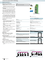
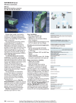
As modern systems and machines become increasingly automated, ever larger
amounts of information need to be processed. The higher data volumes, coupled
with the integration of complex field devices, is demanding more and more in terms of
the performance capabilities of the communication networks used.
The “main arteries” of these networks
consist of various types of serial data link,
which are neither inter-compatible nor capable of satisfying the increasingly stringent
requirements with regard to immunity to interference, range, and speed. Even in harsh
industrial environments, our products ensure interference-free and high-performance data transmission.
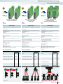
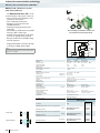
Copper transmission
High-performance isolators, repeaters,
and converters are available for all leading
networks. The devices excel thanks to their
high insulation voltages between the interfaces, which effectively prevent faults and
compensating currents.
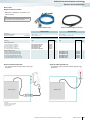
Fiber optic transmission
Fiber optic data transmission has become
the norm, particularly in critical applications
with very high requirements regarding availability. Whether immunity to interference,
high performance, electrical isolation or
network expansion, the use of fiber optic
technology is unavoidable.
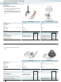
Remote communication
Global networking of machines and systems. Alarm generation, remote maintenance, and continual data acquisition. From
classic analog modems to fast mobile phone
routers: the right system for every application.
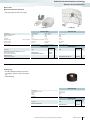
Wireless
Signals from measuring and monitoring
stations often have to be transmitted over
long distances. Modern wireless systems are
a flexible, extendable, and low-cost alternative. Depending on the distance to be covered and the signals to be transmitted, various wireless technologies are available such
as Trusted Wireless, Bluetooth or WLAN.
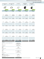
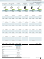
Product overview
352
Copper transmission
RS-485 repeaters for PROFIBUS, Modbus, and company-specific
2-wire systems
Active PROFIBUS termination
Repeater for ControlNet™
Repeaters, segment couplers, and bridge for DeviceNet™
Isolators and converters for RS-232, TTY (CL)
Converters for RS-422, RS-485 4-wire bus systems
Fiber optic transmission
FO converters:
- For PROFIBUS
- For ControlNet™
- For DeviceNet™, and CANopen®
- For RS-485 2-wire bus systems
- For INTERBUS
- For RS-422, RS-485 4-wire bus systems
- For RS-232
Fiber optic cables, tools, and measuring devices
Ethernet networks
Media converters for fiber optics
COMSERVER for serial interfaces
Electrical Ethernet isolators, patch panels, Ethernet cables
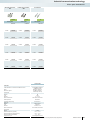
Remote communication
Product overview
Mobile phone network (SMS)
Mobile phone network (GSM/GPRS or EDGE router)
Mobile phone network (UMTS/HSPA router)
Public network (DSL broadband router)
Public network (analog modems)
Private network (extender)
Antennas, surge protection, programming adapters,
interface converters
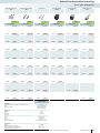
Fieldbus components and systems
Controller boards
Fast connection technology
PROFIBUS cables and fast connection tools
D-SUB fast connection for PROFIBUS
D-SUB fast connection for CANopen® and SafetyBUSp
D-SUB fast connection for Modbus, INTERBUS, RS-232, RS-422,
RS-485
USB and RS-232 cables, RS-485 connection distributors
Wireless data communication
Product overview
Radioline wireless transceivers (2400 MHz, 900 MHz)
I/O extension modules
Bluetooth wireless modules (2400 MHz)
WirelessHART gateway and adapter (2400 MHz)
Bluetooth interface converter (2400 MHz)
Antennas and accessories (2400 MHz)
RAD-Line IO - unidirectional wireless system (900 MHz)
RAD-Line Serial (900 MHz)
RAD-Line Ethernet (900 MHz)
Antennas and accessories (900 MHz)
355 356 357 359 360 363 365 367 369 371 373 374 377 378 406 411 414 420 421 423 425 427 428 431 432 434 439 440 442 444 446 448 451 452 456 458 460 462 466 468 470 474 PHOENIX CONTACT
351
Industrial communication technology
Product overview
Copper transmission
Repeaters
System
Active bus termination
Isolators + converters
TTY (CL)
RS-485
RS-232/RS-422/RS-485
RS-485
Description
Page
Patch panels
Segment couplers
Ethernet
PROFIBUS PA
FOUNDATION
For electrical isolation and
increasing the range
Termination resistor,
for active bus termination
Interface isolators and converters,
for electrical isolation
Passive mini patch panels,
with various connection options
Device coupler,
See section:
Process infrastructure
355
356
360
452
483
FO converters
FO converters
FO converters
FO converters
Fiber optic transmission
FO converters
System
Description
Page
RS-485 2-wire
RS-422
RS-485 4-wire
RS-232
For PROFIBUS,
Termination devices and T-couplers
For ControlNet™,
DeviceNet™, CANopen®,
Termination devices and T-couplers
For INTERBUS,
Termination devices and T-couplers
For RS-485 2-wire and
RS-485 4-wire systems,
Termination devices and T-couplers
For RS-422 and
RS-232 up to 115.2 kbps
Termination devices and T-couplers
365
369
372
371
373
Media converters
COMSERVER
Switches
Secure networks
Switches, INTERFACE modules,
hubs, Power over Ethernet module
Router with firewall for
control cabinet, for mobile use, PCI
See section:
Ethernet networks
See section:
Ethernet networks
6
40
Ethernet networks
System
RS-232
RS-422
RS-485
Ethernet
Ethernet
Description
Page
352
Conversion of 10/100Base-T(X)
Ethernet to fiber optics
WDM technology
451
PHOENIX CONTACT
Isolator
Device servers
for converting serial interfaces
460
Ethernet
4 kV Ethernet ISOLATOR
for electrical isolation
414
Industrial communication technology
Product overview
Remote communication
Mobile phone network
System
I/O
Description
Page
GSM/SMS relays,
6 analog/digital inputs,
4 digital outputs
Public network
UMTS/3G
ADSL Annex A, B
Ethernet
Ethernet/RS-232
423
Controller boards
Page
Analog modem,
for dial-up line/permanent line
operation
Extender (SHDSL)
for in-house cables
428
431
Bluetooth/WirelessHART
RAD-Line (900 MHz)
RS-232
RS-422
RS-485
PC master/slave
controller boards
Master controller boards
for SIMATIC S7-300/400
434
436
Radioline wireless modules
2.4 GHz and 900 MHz
with I/O extension modules
Ethernet
Wireless-MUX
WirelessHART gateway/adapter
Bluetooth interface converter
Unidirectional and
bidirectional wireless systems
From page 448
Fast connection technology
Accessories
SUBCON
Cables, plugs, and tools
System
Description
Ethernet
RS-232/RS-422/RS-485
Wireless data communication
Radioline
System
Page
Ethernet/RS-232
427
Fieldbus components and systems
Description
V.34 (analog)
Industrial mobile phone router, DSL broadband router/modem,
for GPRS/EDGE
with firewall, VPN
and UMTS/HSPA
and serial device server
421
Private network
RS-232
RS-422
RS-485
Ethernet
FO
D-SUB fast connection
for PROFIBUS, CANopen®,
and SafetyBUSp
D-SUB fast connection
for Modbus, INTERBUS,
RS-232, RS-422, RS-485
PROFIBUS cable,
type A Fast Connect
and quick stripping tool
CAT5e cable SF/UTP,
RJ45 plug, crimping pliers,
patch cable
Fiber optic cables,
plugs, and tools
440
444
439
417
378
For additional information, visit www.phoenixcontact.net/products
PHOENIX CONTACT
353
Industrial communication technology
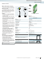
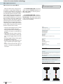
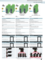
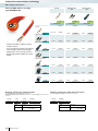
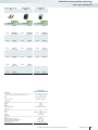
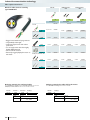
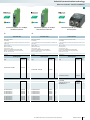
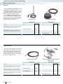
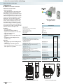
Copper transmission
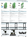
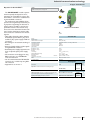
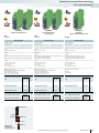
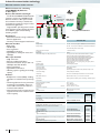
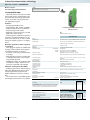
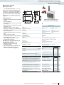
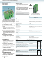
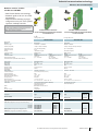
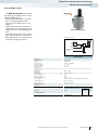
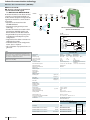
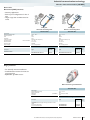
Repeater for PROFIBUS DP
and RS-485 2-wire systems
The performance and availability of bus
systems can be significantly increased by using repeaters. Segmenting the bus with repeaters makes it possible to increase the
permissible extent of the network many
times over and to extend the number of devices. Bus cable short circuits only affect the
relevant segment.
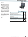
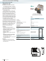
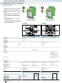
The PSI-REP-PROFIBUS/12MB modular repeater has been specially developed
for the requirements of PROFIBUS systems.
As stipulated by the PROFIBUS installation
guidelines, the PROFIBUS network is connected using D-SUB connectors.
– Automatic data rate detection or fixed
data rate setting via DIP switches
– Suitable for all data rates of up to 12 Mbps
– High-quality 4-way electrical isolation between all interfaces (PROFIBUS (A) //
PROFIBUS (B) // power supply // DIN rail
connector)
– Bit oversampling for reliable detection of
sporadic disturbances
– Bit retiming for unrestricted cascading of
devices
– Filtering of faulty telegrams based on start
delimiter detection
– Routing of supply voltage and data signals
through DIN rail connectors
– Can be combined with PSI-MOS FO converters in a modular way using DIN rail
connectors
As a modular repeater, the PSI-REPRS485W2 can be used in RS-485 2-wire
bus systems. The device supports bus systems that rely on the UART/NRZ data format with a character length of 10 or 11 bits.
– Suitable for data rates of up to 500 kbps
(adjustable via DIP switches)
– High-quality 4-way isolation between all
interfaces (RS-485 (A) // RS-485 (B) //
power supply // DIN rail connector)
– Bit oversampling for reliable detection of
sporadic disturbances
– Bit retiming for unrestricted cascading of
devices
– Can be combined with PSI-MOS FO converters in a modular way using DIN rail
connectors
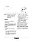
The PSM-ME-RS485/RS485-P compact repeater is designed for universal use in
RS-485 2-wire bus systems.
– Transmission speeds of up to 1.5 Mbps
– Space-saving narrow 22.5 mm device
– High-quality 3-way isolation (RS-485 (A)
// RS-485 (B) // power supply)
– Shipbuilding approval according to DNV
Notes:
1) EMC: Class A product, see page 553
Supply
Supply voltage
Nominal current consumption
RS-485 interface
Data format/coding
Data direction switching
Termination resistor
Transmission speed
Transmission length
Connection method
General data
Bit distortion, input
Bit distortion, output
Bit delay
Alarm output
Test voltage
Ambient temperature range
Electrical isolation
Dimensions
Conformance / approvals
ATEX
UL, USA / Canada
W/H/D
Description
Repeater, for electrical isolation and increased range
for PROFIBUS up to 12 Mbps, 4-way isolation, modular expansion
possible
for RS-485-2-wire bus systems, 4-way isolation, modular expansion possible
for RS-485-2-wire bus systems, 3-way isolation
DIN rail connector (optional), for routing through the supply voltage and data signal, two pieces are required per device
System power supply unit, primary-switched
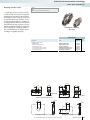
Stub line
PROFIBUS 12 Mbps
100m
100m
Max. 31 devices
= Switch on bus termination resistor
354
PHOENIX CONTACT
Industrial communication technology
Copper transmission
H
H
D
W
D
Repeater for PROFIBUS
H
W
Repeater for RS-485 2-wire systems
Ex: // Applied for: cUL / UL
Basic repeater for RS-485 2-wire systems
Ex: // Applied for: cUL / UL
Technical data
W
D
Ex: // Applied for: cUL / UL
Technical data
Technical data
UART (11 bit, NRZ)
Automatic control, min. station response time 2 bits
24 V DC ±20%
75 mA (24 V DC)
RS-485 interface, in acc. with EIA/TIA-485, DIN 66259-4/RS-485 2wire
UART (11/10 bit switchable ; NRZ)
Automatic control, min. station response time 2 bits
24 V AC/DC ±20%
90 mA (24 V DC)
RS-485 interface, in acc. with EIA/TIA-485, DIN 66259-4/RS-485 2wire
UART (11/10 bit switchable ; NRZ)
Automatic control, min. station response time 1 bits
(external)
Manual and automatic adjustment: 9.6/19.2/45.45/93.75/187.5/500
kbps ; 1.5/3/6/12 Mbps
390 Ω / 180 Ω / 390 Ω (can be connected)
Can be set manually:
4,8/9,6/19,2/38,4/57,6/75/93,75/115,2/136/187,5/375/500 Kbps
390 Ω / 220 Ω / 390 Ω (can be connected)
4.8/ 9.6/ 19.2/ 38.4/ 57.6/ 75/ 93.75/ 115.2/ 136/ 187.5/ 375/ 500/
1500 kbps
max. 1200 m (depends on transmission speed and cable type)
D-SUB-9 socket
max. 1200 m (depends on transmission speed, bus system and cable type)
Plug-in screw connection
max. 1200 m (depends on transmission speed, bus system and cable type)
Plug-in screw connection
Max. ± 35%
< 6.25%
< 1 bit
60 V DC / 42 V AC, 1 A
1.5 kV
-20 °C ... 60 °C
(VCC // TBUS // PROFIBUS (A) // PROFIBUS (B))
35 mm / 99 mm / 105 mm
Max. ± 35%
< 6.25%
< 1 bit
1.5 kV
-20 °C ... 60 °C
(VCC // TBUS // RS-485 (A) // RS-485 (B))
35 mm / 99 mm / 105 mm
Max. ± 35%
< 3.6%
< 200 ns
2 kV
0 °C ... 55 °C
(VCC // RS-485 (A) // RS-485 (B))
22.5 mm / 99 mm / 114.5 mm
II 3 G Ex nAC IIC T4 X
II 3 G Ex nA II T4 X
508 recognized
508 recognized
24 V DC ±20%
90 mA (24 V DC)
PROFIBUS acc. to IEC 61158, RS-485 2-conductor
Ordering data
Ordering data
Type
Order No.
PSI-REP-PROFIBUS/12MB1)
2708863
Pcs. /
Pkt.
Ordering data
Type
Order No.
PSI-REP-RS485W21)
2313096
Pcs. /
Pkt.
Type
Order No.
PSM-ME-RS485/RS485-P1)
2744429
Accessories
1
Accessories
2709561
10
MINI-SYS-PS-100-240AC/24DC/1.5
2866983
1
2709561
10
MINI-SYS-PS-100-240AC/24DC/1.5
2866983
1
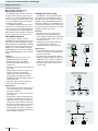
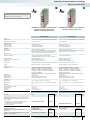
Tree structure
= Switch on bus termination resistor
1
Accessories
ME 17,5 TBUS 1,5/ 5-ST-3,81 GN
Linear structure
Max. 30 devices
= Switch on bus termination resistor
Pcs. /
Pkt.
1
ME 17,5 TBUS 1,5/ 5-ST-3,81 GN
Star structure
508 recognized
Class I, Div. 2, Groups A, B, C, D
Max. 30 devices
= Switch on bus termination resistor
For additional information, visit www.phoenixcontact.net/products
PHOENIX CONTACT
355
Industrial communication technology
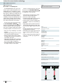
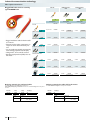
Copper transmission
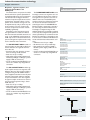
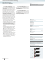
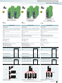
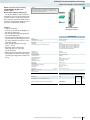
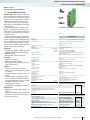
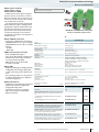
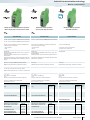
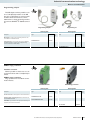
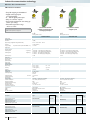
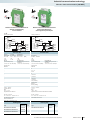
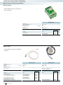
Active bus termination for
PROFIBUS DP and RS-485 networks
Notes:
H
1) EMC: Class A product, see page 553
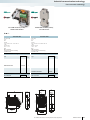
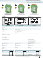
PROFIBUS and RS-485 networks can be
actively terminated using the PSI-TERMINATOR-PB.
This device relies on permanent termination to ensure interference-free communication, particularly in applications that involve alternating bus devices. The bus cable
can be connected using either a plug-in double spring terminal block or a D-SUB socket.
Active programming and diagnostic devices are supplied with power via the D-SUB
connection. This also makes the device ideal
for use as a defined service and measuring
connection within a bus system.
Properties:
– Interference-free bus communication
thanks to active termination
– Fixed programming interface on the network
– Electrical isolation of supply and data interface
– Redundant power supply
– Diagnostic LEDs for voltage and data activity
– Extended temperature range of
-20° +65°C
– Termination can be activated externally
– Compact housing type
– DIN rail mounting
W
D
Active bus termination
Ex: // Applied for: cUL / UL
Technical data
Supply
Supply voltage
24 V DC ± 20% (via plug-in COMBICON screw terminal block)
Nominal current consumption
RS-485 interface
Termination resistor
Transmission speed
Transmission length
45 mA (24 V DC)
PROFIBUS acc. to IEC 61158, RS-485 2-conductor
390 Ω / 220 Ω / 390 Ω (can be connected)
≤ 12 Mbps
≤ 1200 m (depends on transmission speed and cable type)
Nominal output voltage
Strain relief
Connection method
General data
Test voltage
Ambient temperature range
Electrical isolation
Dimensions
Conformance / approvals
ATEX
UL, USA / Canada
5 V DC
Shield connection clamp in spring-cage terminal block
D-SUB 9, COMBICON
W/H/D
1.5 kV
-20 °C ... 65 °C
DIN EN 50178 (RS-485 // VCC)
22.5 mm / 99 mm / 56 mm
II 3 G Ex nA IIC T4 Gc X
508 listed
Ordering data
Application:
Motor Control Center (MCC)
– Replacement of MCC racks
Automatic vehicles
– Mobile industrial trucks that are regularly
coupled to and uncoupled from machining
stations
Changeover tools
– Robot tools with bus interface
Service, programming, and diagnostics
– Fixed programming interface in the bus
system
Description
Order No.
PSI-TERMINATOR-PB1)
2313944
1
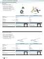
SUBCON-PLUS-PROFIB/90/IDC
SUBCON-PLUS-PROFIB/90/SC
2313672
2313698
1
1
PSM-CABLE-PROFIB/FC
2744652
1
Active termination resistor, for PROFIBUS and RS-485 bus systems, compact design, electrical isolation, bus termination that can
be activated, programming interface
Accessories
PROFIBUS connector, up to 12 Mbps, integrated termination
resistor which can be switched on externally, 9-pos. D-SUB pin,
pin assignment 3, 5, 6, 8
- Angled 90°, IDC connection
- Angled 90°, screw connection
PROFIBUS cable, Fast Connect type, up to 12 Mbps, for permanent connection (02YSY (ST)CY 1X2X22 AWG)
(Length in meters as per customer specifications)
Programming access
SUB
CON
PLU
S
Termination operation
1A
Termination=ON
= Active bus termination resistor
356
PHOENIX CONTACT
Pcs. /
Pkt.
Type
1B
2A
2B
Termination=OFF
= Active bus termination resistor
Industrial communication technology
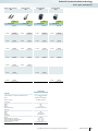
Copper transmission
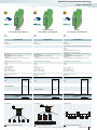
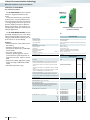
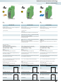
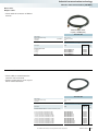
Repeater for ControlNet™
Notes:
H
1) EMC: Class A product, see page 553
The PSI-REP-CNET modular repeater
has been specially developed for the requirements of ControlNet™ systems. The
ControlNet™ connection is established using standard BNC connectors.
The performance and availability of bus
systems can be significantly increased by using repeaters. Segmenting the bus with repeaters makes it possible to increase the
permissible extent of the network many
times over and to extend the number of devices. Another advantage is that bus cable
short circuits are restricted to the relevant
segment.
– High-quality electrical isolation between
all interfaces (ControlNet™ (A) // ControlNet™ (B) // power supply // DIN rail
connector)
– Bit retiming for unrestricted cascading of
devices
– Routing of supply voltage and data signals
through DIN rail connectors
– Redundant power supply supported in the
form of optional system power supply
unit
– All connections can be plugged in using
BNC connectors or a COMBICON
screw terminal block
– Can be combined with the PSI-MOS FO
converters in a modular way using DIN
rail connectors
– Approved for use in zone 2
D
W
Repeater for ControlNet™
Ex:
Technical data
Supply
Supply voltage
Nominal current consumption
ControlNet™ interface
Transmission speed
Transmission length
Connection method
General data
Bit distortion, input
Bit distortion, output
Bit delay
Test voltage
Ambient temperature range
Electrical isolation
Dimensions
Conformance / approvals
ATEX
UL, USA / Canada
24 V DC
38 mA (24 V DC)
ControlNet™ interface, according to EN 50170
5 Mbps
≤ 1000 m
BNC 75 Ω
W/H/D
± 35%
< 6.25%
< 3 bit
1.5 kVrms (50 Hz, 1 min.)
-20 °C ... 60 °C
(VCC // CNET // CNET)
35 mm / 108 mm / 117 mm
II 3 G Ex nA IIC T4 Gc X
508 listed
Ordering data
Description
Pcs. /
Pkt.
Type
Order No.
PSI-REP-CNET1)
2313737
1
Repeater for electrical isolation and increasing the range
Accessories
DIN rail connector (optional), for routing through the supply voltage and data signal, two pieces are required per device
ME 17,5 TBUS 1,5/ 5-ST-3,81 GN
2709561
10
System power supply unit, primary-switched
MINI-SYS-PS-100-240AC/24DC/1.5
2866983
1
For additional information, visit www.phoenixcontact.net/products
PHOENIX CONTACT
357
Industrial communication technology
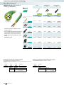
Copper transmission
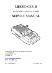
Repeaters, segment couplers, and
bridge for DeviceNet™ and
CANopen®
The infrastructure components for CANbased transmission systems (DeviceNet™
and CANopen®) can be used to implement
interference-free and high-performance
networks. Important requirements such as
segmentation, electrical isolation, and expansion of the network coverage can now
be implemented as easily as almost any network structures. The use of active infrastructure components increases network
availability significantly.
Depending on the transmission speed,
the signal runtimes in cables and devices
limit the maximum achievable network coverage, as the CSMA/CA method typical of
CAN only works in a limited time slot. Repeaters and segment couplers can be configured to eliminate these restrictions.
The PSI-REP-DNET CAN modular repeater provides an electrically isolated connection between two segments with the
same data rate.
– Automatic data rate detection or fixed
data rate setting via DIP switches
– Data rates of up to 1 Mbps
– High-quality 4-way isolation between all
interfaces (CAN (A) // CAN (B) // power
supply // DIN rail connector)
– Can be combined with PSI-MOS FO converters in a modular way using DIN rail
connectors
The PSI-SC-DNET CAN modular segment coupler connects two segments with
different data rates. The segment coupler is
configured using the PSI-CONF software
that is supplied as standard so that only data
telegrams with specific addresses (identifiers) are transmitted to the other segment.
A segment coupler can be used to connect
remote network segments using a slower
CAN data rate.
– Data rates of up to 1 Mbps
– High-quality 4-way isolation between all
interfaces (CAN (A) // CAN (B) // power
supply // DIN rail connector)
– Can be combined with PSI-MOS FO converters in a modular way using DIN rail
connectors
Notes:
1) EMC: Class A product, see page 553
The PSI-BRIDGE-DNET CAN modular bridge connects two segments of a network via different infrastructure solutions.
The segments can operate at the same or
different data rates. Modem/DSL paths,
wireless connections or Ethernet networks
can be used as alternative transmission
technologies via the FL COMSERVER. An
RS-422 interface is integrated as standard
for connecting the desired infrastructure.
The bridge is configured using the PSICONF software that is supplied as standard
so that only data telegrams with specific addresses (identifiers) are transmitted via the
RS-422. The advantage of the bridge is that
it can be used to combine CAN-based networks with alternative infrastructure solutions.
– CAN data rates of up to 1 Mbps
– RS-422 data rates of up to 500 kbps
– High-quality 4-way isolation (CAN //
RS-422 // power supply // DIN rail connector)
– Can be combined with PSI-MOS FO converters in a modular way using DIN rail
connectors
Supply
Supply voltage
Nominal current consumption
RS-422 interface
Termination resistor
Transmission speed
Transmission length
Connection method
CAN interface
Termination resistor
Transmission speed
Transmission length
Connection method
General data
Bit distortion, input
Bit distortion, output
Bit delay
Test voltage
Ambient temperature range
Electrical isolation
Dimensions
Conformance / approvals
ATEX
UL, USA / Canada
W/H/D
Description
Modular repeater for electrical isolation and increasing the range
Modular segment coupler for connecting slow network segments
Modular bridge that allows the use of alternative transmission
technologies
System power supply unit, primary-switched
Stub line
R
Max. 63 devices
= Switch on bus termination resistor
358
PHOENIX CONTACT
Industrial communication technology
Copper transmission
Repeater
for DeviceNet™ and CANopen®
Segment coupler
for DeviceNet™ and CANopen®
Ex:
Bridge
for DeviceNet™ and CANopen®
Ex:
Ex:
Technical data
Technical data
Technical data
24 V DC
55 mA (24 V DC)
24 V DC
55 mA (24 V DC)
24 V DC
55 mA (24 V DC)
RS-422 interface in acc. with ITU-T V.11, EIA/TIA-422, DIN 66348-1
CAN interface, in accordance with ISO/IS 11898 for DeviceNet™,
CAN, CANopen®
124 Ω (integrated and ready to be switched)
≤ 1000 kbps
≤ 5000 m (dependent on the data rate and the protocol used)
CAN interface, in accordance with ISO/IS 11898 for DeviceNet™,
CAN, CANopen®
124 Ω (integrated and ready to be switched)
≤ 1000 kbps
≤ 5000 m (dependent on the data rate and the protocol used)
150 Ω
≤ 500 kbps
≤ 1200 m (dependent on the data rate)
COMBICON plug-in screw terminal block
CAN interface, in accordance with ISO/IS 11898 for DeviceNet™,
CAN, CANopen®
124 Ω (integrated and ready to be switched)
≤ 1000 kbps
≤ 5000 m (dependent on the data rate and the protocol used)
COMBICON plug-in screw terminal block
COMBICON plug-in screw terminal block
COMBICON plug-in screw terminal block
± 35%
< 6.25%
< 1 bit (configurable)
1.5 kVrms (50 Hz, 1 min.)
-20 °C ... 60 °C
(VCC // CAN A // CAN B)
35 mm / 107 mm / 121 mm
± 35%
< 6.25%
≤ 108 bit
1.5 kVrms (50 Hz, 1 min.)
-20 °C ... 60 °C
(VCC // CAN A // CAN B)
35 mm / 107 mm / 121 mm
± 35%
< 6.25%
1.5 kVrms (50 Hz, 1 min.)
-20 °C ... 60 °C
(VCC // CAN // RS-422)
35 mm / 107 mm / 121 mm
II 3 G Ex nA IIC T4 Gc X
II 3 G Ex nA IIC T4 Gc X
508 listed
II 3 G Ex nA IIC T4 Gc X
508 listed
508 listed
Ordering data
Ordering data
Type
Order No.
PSI-REP-DNET CAN1)
2313423
Pcs. /
Pkt.
Ordering data
Type
Order No.
PSI-SC-DNET CAN1)
2313449
Pcs. /
Pkt.
Type
Order No.
1
1
PSI-BRIDGE-DNET CAN1)
Accessories
MINI-SYS-PS-100-240AC/24DC/1.5
Accessories
2866983
1
MINI-SYS-PS-100-240AC/24DC/1.5
Tree structure
Star structure
Pcs. /
Pkt.
2313533
1
2866983
1
Accessories
2866983
1
MINI-SYS-PS-100-240AC/24DC/1.5
Linear structure
R R R
R R R
R
R R
R R
R
R R
Max. 62 devices
= Switch on bus termination resistor
R
= Switch on bus termination resistor
Max. 62 devices
= Switch on bus termination resistor
For additional information, visit www.phoenixcontact.net/products
PHOENIX CONTACT
359
Industrial communication technology
Copper transmission
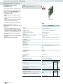
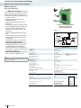
Interface isolator
H
RS-232 / RS-232 interface isolator
The V.24 (RS-232) interface is an asymmetric voltage interface (common signal
ground for all signals). As well as having a
very low signal power, the signal ground is
connected to ground potential. This results
in very little immunity to interference and a
maximum range of 15 m.
A considerably higher level of immunity to
interference can be achieved in industrial
applications by using V.24 (RS-232) isolator
modules. The high-quality 3-way isolation
results in an electrically isolated and interference-proof V.24 (RS-232) interface. This
decoupling also protects the expensive terminal devices against damage.
Features:
– High-quality 3-way isolation up to 2 kV
(VCC // V.24 (RS-232) // V.24 (RS-232))
– Max. transmission rate of up to 115.2
kbps
– 24 V DC or AC power supply suitable for
control cabinet
– Mounting on standard EN DIN rails
– Integrated surge protection with transient discharge to the DIN rail
– In the case of variable cable lengths, the
V.24 (RS-232) connection on the field side
can be established conveniently using
plug-in screw terminal blocks
– Transmission of TxD/RxD data channels
and RTS/CTS control lines
– Active data transmission indicated by separate data indicators for the transmit and
receive channels
Application:
– Higher level of immunity to interference
for industrial conditions
– Compensating currents avoided through
electrical isolation
– Protection of expensive terminal devices
through decoupling
– Optimum protection of both interface
sides thanks to two V.24 (RS-232)/V.24
(RS-232) interface isolators
Notes:
1) EMC: Class A product, see page 553
360
PHOENIX CONTACT
D
W
Electrical Isolation
15 m
RS-232
(V.24)
RS-232
(V.24)
15 m
V.24 (RS-232) interface isolator
Ex: // Applied for: cUL / UL
Technical data
Supply
Supply voltage
Nominal current consumption
V.24 (RS-232) interface
24 V AC/DC ±20%
40 mA (24 V DC)
V.24 (RS-232) interface in acc. with ITU-T V.28, EIA/TIA-232, DIN
66259-1
115.2 kbps
15 m (twisted pair)
D-SUB-9 plug
Plug-in screw connection
Transmission speed
Transmission length
Connection method
General data
Bit distortion
Bit delay
Test voltage
Ambient temperature range
Housing material
Transmission channels
Electrical isolation
Dimensions
Conformance / approvals
UL, USA / Canada
W/H/D
< 5%
< 3 µs
2 kV
0 °C ... 55 °C
PA
4 (2/2), RxD, TxD, RTS, CTS ; full duplex
(VCC // V.24 (RS-232) (A) // V.24 (RS-232) (B))
22.5 mm / 99 mm / 118.6 mm
508 recognized
Class I, Div. 2, Groups A, B, C, D
Ordering data
Description
Pcs. /
Pkt.
Type
Order No.
PSM-ME-RS232/RS232-P1)
2744461
1
2761059
2799474
1
1
Interface isolator, for electrical isolation of RS-232 (V.24) interfaces, four channels, rail-mountable
Accessories
RS-232-D-SUB cable, length: 2 m
- 9-pos. socket on 25-pos. socket
- 9-pos. socket on 9-pos. socket
PSM-KA 9 SUB 25/BB/2METER
PSM-KA9SUB9/BB/2METER
Industrial communication technology
Copper transmission
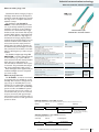
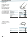
Interface converters
H
RS-232 / TTY interface converter
This converter converts a V.24 (RS-232)
interface into a 20 mA TTY current loop interface bidirectionally.
The interference immune TTY signal allows problem-free data transmission over
distances of up to 1000 m using a twistedpair and shielded 4-wire cable.
Features:
– Conversion of V.24 (RS-232) TxD/RxD
full duplex data signals into the TTY current loop standard
– Semi-active, active or passive TTY operating mode, depending on pin assignment
– Transmission speed of up to 19.2 kbps
– Transmission distances of up to 1000 m in
active TTY mode
– 24 V DC or AC power supply suitable for
control cabinet
– Active data transmission indicated by separate data indicators for the transmit and
receive channels
– Convenient connection for variable cable
lengths, enabling the TTY connection on
the field side to be established via plug-in
screw terminal blocks
– V.24 (RS-232) connection via D-SUB 9
and standard V.24 (RS-232) cable
– High-quality 3-way isolation up to 2 kV
(VCC // V.24 (RS-232) // TTY)
– Mounting on standard EN DIN rails
– Integrated surge protection with transient discharge to the DIN rail
Application:
The following tasks are generally solved
with the converters (see illustration):
– Interface adaptation between V.24
(RS-232) and TTY interfaces
– Increased range of up to 1000 m
– Programming connection between PC
(V.24 (RS-232)) and, for example, S5 controllers with TTY programming interface
for temporary coupling
D
W
Interface adaptation
RS-232
(V.24)
RS-232
(V.24)
15 m
1000 m
TTY converter, 2 channels
TTY
TTY
Ex: // Applied for: cUL / UL
Technical data
Supply
Supply voltage
Nominal current consumption
V.24 (RS-232) interface
Transmission speed
Transmission length
Connection method
TTY interface
Transmission speed
Transmission length
Connection method
Operating mode
Load
General data
Bit distortion
Bit delay
Test voltage
Ambient temperature range
Housing material
Transmission channels
Electrical isolation
Dimensions
Conformance / approvals
UL, USA / Canada
24 V AC/DC ±20%
75 mA (24 V DC)
V.24 (RS-232) interface in acc. with ITU-T V.28, EIA/TIA-232, DIN
66259-1
≤ 19.2 kbps
15 m (twisted pair)
D-SUB-9 plug
TTY interface, CL2 in acc. with DIN 66348-1
≤ 19.2 kbps
1000 m (twisted pair)
Plug-in screw connection
Active, semi active, passive
≤ 500 Ω
W/H/D
< 5%
< 3 µs
2 kV
0 °C ... 55 °C
PA
2 (1/1), RxD, TxD, full duplex
(VCC // V.24 (RS-232) // TTY)
22.5 mm / 99 mm / 118.6 mm
508 recognized
Class I, Div. 2, Groups A, B, C, D
Ordering data
Description
Type
Order No.
Pcs. /
Pkt.
Interface converter, for conversion from RS-232 (V.24) to TTY,
with electrical isolation, two channels, rail-mountable
PSM-ME-RS232/TTY-P1)
2744458
1
2761059
2799474
1
1
Accessories
RS-232-D-SUB cable, length: 2 m
- 9-pos. socket on 25-pos. socket
- 9-pos. socket on 9-pos. socket
PSM-KA 9 SUB 25/BB/2METER
PSM-KA9SUB9/BB/2METER
Notes:
1) EMC: Class A product, see page 553
For additional information, visit www.phoenixcontact.net/products
PHOENIX CONTACT
361
Industrial communication technology
Copper transmission
Interface converters
RS-232 (V.24) / RS-422 (V.11)
RS-232 (V.24) / RS-485
The RS-422 standard can be used to set
up rapid, interference-free point-to-point
connections in industrial applications. Connections covering a distance of up to 1200
m can be established using a twisted-pair
and shielded 4-wire cable.
The RS-485 standard allows more than
two devices to communicate with one another. Converting the V.24 (RS-232) pointto-point interface into the bus-capable RS485 standard makes it possible to network
up to 32 devices via a 2 or 4-wire cable.
PSM-ME-RS232/RS485-P
This interface converter converts
TxD/RxD data signals with speeds of up to
115.2 kbps on the V.24 (RS-232) interface
bidirectionally into either RS-422 or RS-485
signals. The V.24 (RS-232) connection is established via a 9-pos. D-SUB, and the RS422/RS-485 field connection is established
using COMBICON plug-in screw terminal
blocks.
Features:
– RS-422 4-wire point-to-point mode
– RS-485 2-wire mode, half duplex
– RS-485 4-wire mode, full duplex
– Automatic RS-485 transmit/receive
changeover
– Transmission speed between 4.8 kbps and
115.2 kbps
– Integrated data indicator for dynamic indication of send and receive data
– High-quality 3-way isolation between
power supply, V.24 (RS-232), and RS422/485 for reliable decoupling of the potentials with 2 kV
– Integrated surge protection with transient discharge to the DIN rail
Applications:
– Fast and interference-free point-to-point
connection between two V.24 (RS-232)
interfaces via RS-422
– Increase in range or remote transmission
up to 1200 m
– Programming or parameterizing link between PC (V.24 (RS-232)) and a piece of
equipment such as a PLC or variable frequency drive with an RS-422 connection
– A temporary programming or parameterizing link can be set up between a PC
(V.24 (RS-232)) and a piece of equipment
such as a PLC or variable frequency drive
with an RS-485 connection
PSM-EG-RS 232/RS 422-P/4K
The PSM-EG... control cabinet module
also converts the V.24 (RS-232) signals in
full duplex mode with a data rate of up to
64 kbps to the powerful RS-422 standard.
However, in addition to the TxD/RxD transmit and receive channels, the converter also
provides two further channels for transmitting RTS and CTS control lines.
Features:
– RS-422 4-wire point-to-point mode
– High-quality 3-way isolation between
power supply, V.24 (RS-232), and RS-422
for reliable electrical isolation of the potentials with 2.5 kV
– Integrated surge protection with transient discharge to the DIN rail
– Transmission speed of up to 64 kbps
Applications:
– Fast and interference-free point-to-point
connection between two V.24 (RS-232)
interfaces via RS-422
– Programming or parameterizing link between PC (V.24 (RS-232)) and a piece of
equipment such as a PLC or variable frequency drive with an RS-422 connection
– Increased range of up to 1200 m, incl.
control cables
Remote transmission
RS-232
(V.24)
1200 m
RS-232
(V.24)
Interface adaptation
PHOENIX CONTACT
Programming connection
RS-232
(V.24)
15 m
RS-485
RS-422
(V.11)
RS-485
Master interface connection on an
RS-485 2-wire and 4-wire system
Master
RS-232
(V.24)
RS-485
2-/4-wire
max. 31
Networking of RS-232 devices
RS-232
(V.24)
RS-485
2-/4-wire
max. 32 devices
RS-232
(V.24)
362
RS-422
(V.11)
RS-232
(V.24)
Industrial communication technology
Copper transmission
H
H
D
W
D
W
Notes:
1) EMC: Class A product, see page 553
V.24 (RS-232) converter for
RS-422 and RS-485, 2 channels
V.24 (RS-232) converter for
RS-422, 4 channels
Ex: // Applied for: cUL / UL
Technical data
Technical data
Transmission speed
Connection method
RS-422 interface
24 V AC/DC ±20%
85 mA (24 V DC)
V.24 (RS-232) interface in acc. with ITU-T V.28, EIA/TIA-232, DIN
66259-1
115.2 kbps
D-SUB-9 plug
RS-422 interface in acc. with ITU-T V.11, EIA/TIA-422, DIN 66348-1
24 V DC ±20%
130 mA (24 V DC)
V.24 (RS-232) interface in acc. with ITU-T V.28, EIA/TIA-232, DIN
66259-1
64 kbps
D-SUB-9 plug
RS-422 interface in acc. with ITU-T V.11, EIA/TIA-422, DIN 66348-1
Termination resistor
Transmission speed
Transmission length
Connection method
RS-485 interface
390 Ω / 180 Ω / 390 Ω (can be connected)
115.2 kbps
1200 m (twisted pair)
Plug-in screw connection
RS-485 interface in acc. with EIA/TIA-485, DIN 66259-1
510 Ω / 150 Ω / 510 Ω (can be connected)
64 kbps
1200 m (twisted pair)
D-SUB-15 plug
Data direction switching
Termination resistor
Transmission length
Connection method
General data
Bit distortion
Bit delay
Test voltage
Ambient temperature range
Housing material
Transmission channels
Electrical isolation
Dimensions
Conformance / approvals
UL, USA / Canada
Automatic control or via RTS/CTS
390 Ω / 180 Ω / 390 Ω (can be connected)
1200 m (twisted pair)
Plug-in screw connection
-
≤ 5%
≤ 3 µs
2 kV
0 °C ... 55 °C
PA
2 (1/1), RxD, TxD, full duplex
(VCC // V.24 (RS-232) // RS-485)
22.5 mm / 99 mm / 118.6 mm
≤ 5%
≤ 3 µs
2.5 kV
0 °C ... 50 °C
ABS
4 (2/2), RxD, TxD, RTS, CTS ; full duplex
(VCC // V.24 (RS-232) // RS-422)
45 mm / 75 mm / 110 mm
508 recognized
Class I, Div. 2, Groups A, B, C, D
cUL 508 recognized
Supply
Supply voltage
Nominal current consumption
V.24 (RS-232) interface
W/H/D
Ordering data
Description
Type
Ordering data
Order No.
Pcs. /
Pkt.
Pcs. /
Pkt.
Type
Order No.
PSM-EG-RS232/RS422-P/4K1)
2761266
1
2761059
2799474
1
1
Interface converter, for conversion from RS-232 (V.24) to RS485, with electrical isolation, rail-mountable, changeover of data
direction self-controlling or through RTS/CTS
- 2 channels
Interface converter, for conversion from RS-232 (V.24) to RS-422
(V.11), with electrical isolation, rail-mountable
PSM-ME-RS232/RS485-P1)
2744416
1
- 4 channels
Accessories
RS-232-D-SUB cable, length: 2 m
- 9-pos. socket on 25-pos. socket
- 9-pos. socket on 9-pos. socket
PSM-KA 9 SUB 25/BB/2METER
PSM-KA9SUB9/BB/2METER
Accessories
2761059
2799474
1
1
PSM-KA 9 SUB 25/BB/2METER
PSM-KA9SUB9/BB/2METER
For additional information, visit www.phoenixcontact.net/products
PHOENIX CONTACT
363
Industrial communication technology
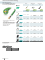
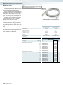
Fiber optics transmission
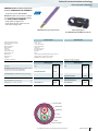
FO converters for PROFIBUS
Notes:
1) EMC: Class A product, see page 553
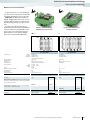
The PSI-MOS-PROFIB/FO... devices
convert copper-based PROFIBUS interfaces
to fiber optics.
The integrated optical diagnostics allow
permanent monitoring of the FO paths during installation and also during operation.
The floating switch contact is activated
when the signal output on the fiber optic
paths drops to a critical level.
Depending on which wavelength is used in
conjunction with the corresponding fibers,
transmission distances of 70 m to 45 km
can be achieved between two devices. Depending on the wavelength, devices can be
used with polymer, HCS, and fiberglass.
– Automatic data rate detection or fixed
data rate setting via DIP switches
– Suitable for all data rates of up to 12 Mbps
– Integrated optical diagnostics for continuous monitoring of fiber optic paths
– Floating switch contact for leading alarm
generation in relation to critical fiber optic paths
– High-quality electrical isolation between
all interfaces (PROFIBUS // fiber optic
ports // power supply // DIN rail connector)
– Bit retiming for any cascading depth
– Routing of supply voltage and data signals
through DIN rail connectors
– Redundant power supply supported in the
form of optional system power supply
unit
– Can be combined with the PSI copper repeater for PROFIBUS in a modular way
using DIN rail connectors
The PSI-MOS-PROFIB/FO... E terminal devices convert a PROFIBUS interface
to a FO cable. They are ideal for point-topoint connections.
The PSI-MOS-PROFIB/FO... T T-couplers allow the interface to be converted to
two FO cables. They can be used to create
linear structures and ring structures for increased system availability.
Supply
Supply voltage range
Nominal current consumption
RS-485 interface
Data format/coding
Transmission speed
Transmission length
Connection method
Optical interface
Connection
Wavelength
Transmission length incl. 3 dB system reserve
General data
Bit delay
Ambient temperature range
Dimensions
Conformance / approvals
ATEX
W/H/D
UL, USA / Canada
Description
Terminal device, for converting data signals from PROFIBUS
FMS/DP to an FO cable
T-coupler, for converting data signals from PROFIBUS FMS/DP to
two FO cables
DIN rail connector (optional), for routing through the supply voltage and data signal, two pieces are required per device
DIN rail connector, (optional), for routing through the supply voltage, 2 required per device
System power supply unit, primary-switched
Max. 31
E
FO
Max. 31
T
FO
Max. 31
T
FO
Linear structure
364
PHOENIX CONTACT
Industrial communication technology
Fiber optics transmission
H
H
D
W
H
W
D
PROFIBUS
polymer and HCS fibers
W
D
PROFIBUS
HCS and fiberglass
(multi mode)
Ex:
PROFIBUS
fiberglass
(multi mode and single mode)
Ex:
Technical data
Technical data
Technical data
18 V DC ... 30 V DC
100 mA (24 V DC)
PROFIBUS acc. to IEC 61158, RS-485 2-wire, half duplex,
automatic control
UART (11 bit, NRZ)
≤ 12 Mbps
≤ 1200 m (depending on the data rate, with shielded, twisted pair
data cable)
D-SUB-9 socket
18 V DC ... 30 V DC
120 mA (24 V DC)
PROFIBUS acc. to IEC 61158, RS-485 2-wire, half duplex,
automatic control
UART (11 bit, NRZ)
≤ 12 Mbps
≤ 1200 m (depending on the data rate, with shielded, twisted pair
data cable)
D-SUB-9 socket
18 V DC ... 32 V DC
170 mA (24 V DC)
PROFIBUS acc. to IEC 61158, RS-485 2-wire, half duplex,
automatic control
UART (11 bit, NRZ)
≤ 12 Mbps
≤ 1200 m (depending on the data rate, with shielded, twisted pair
data cable)
D-SUB-9 socket
F-SMA
660 nm
70 m (with F-P 980/1000 230 dB/km with quick mounting connector)
400 m (with F-K 200/230 10 dB/km with quick mounting connector)
B-FOC (ST®)
850 nm
2600 m (with F-G 50/125 2.5 dB/km)
3300 m (with F-G 62.5/125 3.0 dB/km)
800 m (with F-K 200/230 10 dB/km with quick mounting connector)
SC duplex
1300 nm
25 km (with F-G 50/125 0.7 dB/km at 1300 nm)
22 km (with F-G 62.5/125 0.8 dB/km at 1300 nm)
45 km (with F-E 9/125 0.4 dB/km at 1300 nm)
< 1 bit
-20 °C ... 60 °C
35 mm / 99 mm / 106 mm
< 1 bit
-20 °C ... 60 °C
35 mm / 99 mm / 106 mm
< 1 bit
-20 °C ... 60 °C
35 mm / 105 mm / 106 mm
II 3 G Ex nAC IIC T4 X
II (2) GD [Ex op is] IIC (PTB 06 ATEX 2042 U)
II 3 G Ex nAC IIC T4 X
II (2) GD [Ex op is] IIC (PTB 06 ATEX 2042 U)
II 3 G Ex nA nC IIC T4 Gc X
Class I, Zone 2, AEx nc IIC T5
Class I, Zone 2, Ex nC nL IIC T5 X
Class I, Div. 2, Groups A, B, C, D
Class I, Zone 2, AEx nc IIC T5
Class I, Zone 2, Ex nC nL IIC T5 X
Class I, Div. 2, Groups A, B, C, D
508 listed
508 recognized
Ordering data
Ordering data
Type
Order No.
PSI-MOS-PROFIB/FO 660 E1)
2708290
PSI-MOS-PROFIB/FO 660 T1)
Pcs. /
Pkt.
Ordering data
Type
Order No.
1
PSI-MOS-PROFIB/FO 850 E1)
2708274
2708287
1
PSI-MOS-PROFIB/FO 850 T1)
ME 17,5 TBUS 1,5/ 5-ST-3,81 GN
2709561
10
ME 17,5 TBUS 1,5/PP000-3,81 BK
2890014
MINI-SYS-PS-100-240AC/24DC/1.5
2866983
Pcs. /
Pkt.
Pcs. /
Pkt.
Type
Order No.
1
PSI-MOS-PROFIB/FO1300 E1)
2708559
1
2708261
1
PSI-MOS-PROFIB/FO1300 T1)
2708892
1
ME 17,5 TBUS 1,5/ 5-ST-3,81 GN
2709561
10
ME 17,5 TBUS 1,5/ 5-ST-3,81 GN
2709561
10
10
ME 17,5 TBUS 1,5/PP000-3,81 BK
2890014
10
ME 17,5 TBUS 1,5/PP000-3,81 BK
2890014
10
1
MINI-SYS-PS-100-240AC/24DC/1.5
2866983
1
MINI-SYS-PS-100-240AC/24DC/1.5
2866983
1
Accessories
Accessories
Accessories
max. 31
........
max. 31
Max. 31
T
T
E
T
T
T
...
...
FO
FO
max. 31
max. 31
max. 31
max. 31
max. 31
max. 31
T
T
........
........
E
E
E
E
E
T
T
...
T
T
...
T
T
...
T
T
...
FO
T
Max. 31
Star structure
Tree structure
FO
Redundant FO ring
For additional information, visit www.phoenixcontact.net/products
max. 31
........
PHOENIX CONTACT
365
Industrial communication technology
Fiber optics transmission
FO converters for ControlNet™
Notes:
1) EMC: Class A product, see page 553
With the infrastructure components for
ControlNet™, copper-based and fiber optic networks can benefit from the advantages of active devices. The main advantage is
the electrically isolated connection of bus
devices, which means that the negative effects of voltage equalization currents and
electromagnetic interference on the bus cables are a thing of the past. In addition, bus
cable short circuits only affect the specific
potential segment concerned. In addition to
interference-free and electrically isolated
networking, the use of fiber optic technology also enables longer branch lines and star
and tree structures to be created.
– Integrated optical diagnostics for continuous monitoring of fiber optic paths
– Floating switch contact for leading alarm
generation in relation to critical fiber optic paths
– High-quality electrical isolation between
all interfaces (ControlNet™ // fiber optic
ports // power supply // DIN rail connector)
– Routing of supply voltage and data signals
through DIN rail connectors
– Redundant power supply supported in the
form of optional system power supply
unit
– Can be combined with the PSI copper repeater in a modular way using DIN rail
connectors
The PSI-MOS-CNET/FO... E terminal
device converts a PROFIBUS interface to a
fiber optic cable. It is ideal for point-topoint connections.
The PSI-MOS-CNET/FO... T T-coupler allows the interface to be converted to
two FO cables. This device can be used to
create redundant network structures for increased system availability.
Supply
Supply voltage range
Nominal current consumption
ControlNet™ interface
Transmission speed
Transmission length
Connection method
Optical interface
Connection
Wavelength
Transmission length incl. 3 dB system reserve
General data
Bit delay
Alarm output
Test voltage
Ambient temperature range
Electrical isolation
Dimensions
Conformance / approvals
ATEX
W/H/D
UL, USA / Canada
Description
Fiber optic converter, termination device for converting data signals to a fiber optic cable
Fiber optic converter, T-coupler for converting data signals to two
fiber optic cables
DIN rail connector (optional), for routing through the supply voltage and data signal, two pieces are required per device
System power supply unit, primary-switched
Max. 47
E
Max. 47
T
FO
E
T
Max. 47
Point-to-point connection
366
PHOENIX CONTACT
Max. 47
Redundant
point-to-point connection
Industrial communication technology
Fiber optics transmission
H
H
D
W
W
D
ControlNet™,
one optical channel
ControlNet™,
two optical channels
Ex:
Ex:
Technical data
Technical data
18 V DC ... 30 V DC (via plug-in COMBICON screw terminal block)
18 V DC ... 30 V DC (via plug-in COMBICON screw terminal block)
100 mA (24 V DC)
ControlNet™ interface, according to EN 50170
5 Mbps
≤ 1000 m
BNC 75 Ω
100 mA (24 V DC)
ControlNet™ interface, according to EN 50170
5 Mbps
≤ 1000 m
BNC 75 Ω
B-FOC (ST®)
850 nm
1200 m (with F-K 200/230 8 dB/km with quick mounting connector)
3100 m (with F-G 50/125 2.5 dB/km)
3000 m (with F-G 62.5/125 3.0 dB/km)
B-FOC (ST®)
850 nm
1200 m (with F-K 200/230 8 dB/km with quick mounting connector)
3100 m (with F-G 50/125 2.5 dB/km)
3000 m (with F-G 62.5/125 3.0 dB/km)
< 3 bit
18 V DC ... 30 V DC, 500 mA
1.5 kVrms (50 Hz, 1 min.)
-20 °C ... 60 °C
(VCC // ControlNet™)
35 mm / 105 mm / 117 mm
< 3 bit
18 V DC ... 30 V DC, 500 mA
1.5 kVrms (50 Hz, 1 min.)
-20 °C ... 60 °C
(VCC // ControlNet™)
35 mm / 105 mm / 117 mm
II (2) D [Ex op is Db] IIIC (PTB 06 ATEX 2042 U)
II (2) G [Ex op is Gb] IIC (PTB 06 ATEX 2042 U)
II 3 G Ex nA IIC T4 Gc X
II (2) D [Ex op is Db] IIIC (PTB 06 ATEX 2042 U)
II (2) G [Ex op is Gb] IIC (PTB 06 ATEX 2042 U)
II 3 G Ex nA IIC T4 Gc X
508 listed
508 listed
Ordering data
Ordering data
Type
Order No.
PSI-MOS-CNET/FO 850 E1)
2313711
Pcs. /
Pkt.
Type
Order No.
Pcs. /
Pkt.
1
PSI-MOS-CNET/FO 850 T1)
2313724
1
ME 17,5 TBUS 1,5/ 5-ST-3,81 GN
2709561
10
MINI-SYS-PS-100-240AC/24DC/1.5
2866983
1
Accessories
Accessories
ME 17,5 TBUS 1,5/ 5-ST-3,81 GN
2709561
10
MINI-SYS-PS-100-240AC/24DC/1.5
2866983
1
Max. 47
E
max. 47
Max. 47
FO
T
T
E
T
T
...
...
FO
Max. 47
T
FO
max. 47
max. 47
max. 47
max. 47
FO
Max. 47
E
E
E
E
E
T
T
...
T
T
...
T
T
...
T
T
...
Max. 47
FO
Linear structure
T
Star structure
Tree structure
For additional information, visit www.phoenixcontact.net/products
FO
PHOENIX CONTACT
367
Industrial communication technology
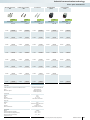
Fiber optics transmission
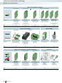
FO converters for
DeviceNet™ and CANopen®
The PSI-MOS-DNET... fiber optic transmission system enables DeviceNet™ and
CANopen® users to benefit from simple
and interference-free networking based on
fiber optics. In addition, bus cable short circuits only affect the specific potential segment concerned. This increases overall
availability, and improves flexibility when designing the bus topology. The use of fiber
optic technology enables branch lines and
star and tree structures to be created.
The 22.5 mm space-saving devices from
the PSI-MOS-DNET CAN/FO series
feature an internal backplane. The maximum
network expansion that can be achieved
(sum total of copper and fiber optic cables)
essentially depends on the data rate used.
– Data rates of up to 800 kbps, set via DIP
switches
– Integrated optical diagnostics for continuous monitoring of fiber optic paths
– Floating switch contact in basic module
for leading alarm generation in relation to
critical fiber optic paths
– High-quality electrical isolation between
all interfaces (DeviceNet™ // fiber optic
port // power supply // backplane)
– Integrated backplane for routing through
the supply voltage and data signals
Notes:
1) EMC: Class A product, see page 553
Thanks to extended functions, the modular devices in the PSI-MOS-DNET/FO
series support network expansion that is
not dependent on the data rate.
– Automatic data rate detection or fixed
data rate setting via DIP switches
– Data rates of up to 1000 kbps
– Integrated optical diagnostics for continuous monitoring of fiber optic paths
– Floating switch contact for leading alarm
generation in relation to critical fiber optic paths
– High-quality electrical isolation between
all interfaces (DeviceNet™ // fiber optic
ports // power supply // DIN rail connector)
– Routing of supply voltage and data signals
through DIN rail connectors
– Redundant power supply supported in the
form of optional system power supply
unit
– Can be combined with the PSI copper repeater in a modular way using DIN rail
connectors
Supply
Supply voltage range
Nominal current consumption
CAN interface
Termination resistor
Transmission speed
Transmission length
Connection method
Optical interface
Connection
Wavelength
Transmission length incl. 3 dB system reserve
General data
Bit delay
Alarm output
Test voltage
Ambient temperature range
Dimensions
Conformance / approvals
ATEX
W/H/D
UL, USA / Canada
Description
Basic module for conversion of the CAN-based interface to a
fiber optics interface
Extension module with a fiber optics interface
FO converter, terminal device for converting a CAN-based interface to a fiber optic cable
FO converter, T-coupler for converting a CAN-based interface to
two fiber optic cables
BE
B
FO
B
Branch line / redundant branch line
368
PHOENIX CONTACT
BE
Industrial communication technology
Fiber optics transmission
DeviceNet™ and CANopen®
Polymer and HCS fibers
DeviceNet™ and CANopen®
HCS and fiberglass
(multi mode)
Ex:
DeviceNet™ and CANopen®
HCS and fiberglass
(multi mode) external backplane
Ex:
Ex:
Technical data
Technical data
Technical data
10 V DC ... 30 V DC (via plug-in COMBICON screw terminal block)
10 V DC ... 30 V DC (via plug-in COMBICON screw terminal block)
11 V DC ... 30 V DC (via plug-in COMBICON screw terminal block)
100 mA (24 V DC)
CAN interface, in accordance with ISO/IS 11898 for DeviceNet™,
CAN, CANopen®
120 Ω (can be connected)
≤ 800 kbps
≤ 5000 m (dependent on the data rate and the protocol used)
100 mA (24 V DC)
CAN interface, in accordance with ISO/IS 11898 for DeviceNet™,
CAN, CANopen®
120 Ω (can be connected)
≤ 800 kbps
≤ 5000 m (dependent on the data rate and the protocol used)
130 mA (24 V DC)
CAN interface, in accordance with ISO/IS 11898 for DeviceNet™,
CAN, CANopen®
124 Ω (integrated and ready to be switched)
≤ 1000 kbps
≤ 5000 m (dependent on the data rate and the protocol used)
Plug-in screw connection
Plug-in screw connection
COMBICON plug-in screw terminal block
(ST®)
F-SMA
660 nm
100 m (with F-P 980/1000 230 dB/km with quick mounting connector)
800 m (with F-K 200/230 10 dB/km with quick mounting connector)
B-FOC
850 nm
2800 m (with F-K 200/230 8 dB/km with quick mounting connector)
4800 m (with F-G 50/125 2.5 dB/km)
4200 m (with F-G 62.5/125 3.0 dB/km)
B-FOC (ST®)
850 nm
1800 m (with F-K 200/230 8 dB/km with quick mounting connector)
4600 m (with F-G 50/125 2.5 dB/km)
4200 m (with F-G 62.5/125 3.0 dB/km)
< 1 bit
60 V DC / 42 V AC, 0.46 A
1.5 kVrms (50 Hz, 1 min.)
-20 °C ... 60 °C
22.5 mm / 99 mm / 114.5 mm
< 1 bit
60 V DC / 42 V AC, 0.46 A
1.5 kVrms (50 Hz, 1 min.)
-20 °C ... 60 °C
22.5 mm / 99 mm / 114.5 mm
< 1 bit (configurable)
1.5 kVrms (50 Hz, 1 min.)
-20 °C ... 60 °C
35 mm / 102 mm / 119 mm
II 3 G Ex nAC IIC T4 X
II (2) GD [Ex op is] IIC (PTB 06 ATEX 2042 U)
II 3 G Ex nAC IIC T4 X
II (2) GD [Ex op is] IIC (PTB 06 ATEX 2042 U)
II (2) D [Ex op is Db] IIIC (PTB 06 ATEX 2042 U)
II (2) G [Ex op is Gb] IIC (PTB 06 ATEX 2042 U)
II 3 G Ex nA IIC T4 Gc X
Class I, Zone 2, AEx nc IIC T5
Class I, Div. 2, Groups A, B, C, D
Class I, Zone 2, AEx nc IIC T5
Class I, Div. 2, Groups A, B, C, D
508 listed
Ordering data
Ordering data
Type
Order No.
PSI-MOS-DNET CAN/FO 660/BM1)
2708054
PSI-MOS-DNET CAN/FO 660/EM1)
2708067
FO
Pcs. /
Pkt.
Type
Order No.
1
PSI-MOS-DNET CAN/FO 850/BM1)
2708083
1
1
PSI-MOS-DNET CAN/FO 850/EM1)
2708096
1
Pcs. /
Pkt.
Type
Order No.
PSI-MOS-DNET/FO 850 E1)
2313999
1
PSI-MOS-DNET/FO 850 T1)
2313986
1
FO
BE
B
Pcs. /
Pkt.
Ordering data
max. 63
B
BE E E
BE BE
...20
BE
T
...20
T
...
FO
FO
...64x
Linear structure
...64x
...64x
B
B
B
B
max. 63
BE
Star structure / redundant star structure
BE
BE
T
T
max. 63
...
Tree structure
For additional information, visit www.phoenixcontact.net/products
T
T
...
max. 63
T
T
...
max. 63
T
T
...
FO
PHOENIX CONTACT
369
Industrial communication technology
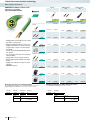
Fiber optics transmission
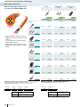
Fiber optic converters
for RS-485 2-wire bus systems
The RS-485 2-wire interface is the most
widely used interface in the field of automation technology. Well-known bus systems,
such as SUCONET K, Modbus ASCII, Modbus RTU, S-BUS, and DH-485, are all based
on this interface, as are many other company-specific bus systems.
The PSI-MOS-RS485W2/FO... FO
converters convert the electrical data signal
into an optical one by protocol transparent
means.
The integrated optical diagnostics allow
permanent monitoring of the FO paths during installation and also during operation.
The floating switch contact is activated
when the signal output on the fiber optic
paths drops to a critical level.
Depending on which wavelength is used in
conjunction with the corresponding fibers,
distances of 100 m to 45 km can be
achieved between two devices.
– Automatic data rate detection or fixed
data rate setting via DIP switches
– Suitable for data rates of up to 500 kbps
– Integrated optical diagnostics for continuous monitoring of fiber optic paths
– Floating switch contact for leading alarm
generation in relation to critical fiber optic paths
– High-quality electrical isolation between
all interfaces (RS-485 // fiber optic ports //
power supply // DIN rail connector)
– Routing of supply voltage and data signals
through DIN rail connectors
– Redundant power supply supported in the
form of optional system power supply
unit
– Can be combined with the PSI copper repeater in a modular way using DIN rail
connectors
Notes:
1) EMC: Class A product, see page 553
The PSI-MOS-RS485W2/FO... E termination devices convert an RS-485 interface to a fiber optic cable. They are ideal for
point-to-point connections.
The PSI-MOS-RS485W2/FO... T Tcouplers allow the interface to be converted to two FO cables. They can be used to
create linear structures and redundant
structures for increased system availability.
Supply voltage range
Nominal current consumption
RS-485 interface
Data format/coding
Termination resistor
Transmission speed
Transmission length
Connection method
Optical interface
Connection
Wavelength
Transmission length incl. 3 dB system reserve
General data
Bit delay
Alarm output
Test voltage
Ambient temperature range
Dimensions
Conformance / approvals
ATEX
W/H/D
UL, USA / Canada
Description
Terminal device, for converting data signals from RS-485 2-wire
to an FO cable
T-coupler, for converting data signals from RS-485 2-wire to two
FO cables
DIN rail connector (optional), for routing through the supply voltage and data signal, two pieces are required per device
DIN rail connector, (optional), for routing through the supply voltage, 2 required per device
System power supply unit, primary-switched
Max. 31
E
Max. 31
T
FO
E
T
Max. 31
Point-to-point connection
370
PHOENIX CONTACT
Max. 31
Redundant
point-to-point connection
Industrial communication technology
Fiber optics transmission
H
H
D
W
D
H
W
RS-485 2-wire
polymer and HCS fibers
W
D
RS-485 2-wire
HCS and fiberglass
(multi mode)
Ex:
RS-485 2-wire
fiberglass
(multi mode and single mode)
Ex:
Technical data
Technical data
Technical data
18 V DC ... 30 V DC
100 mA (24 V DC)
RS-485 interface, 2-wire
UART (11/10 bit switchable ; NRZ), slip-tolerant
390 Ω / 220 Ω / 390 Ω (can be connected)
4,8/ 9,6/ 19,2/ 38,4/ 57,6/ 75/ 93,75/ 115,2/ 136/ 187,5/ 375/ 500
≤ 1200 m (depending on the data rate, with shielded, twisted data
cable)
Plug-in screw connection
18 V DC ... 30 V DC
120 mA (24 V DC)
RS-485 interface, 2-wire
UART (11/10 bit switchable ; NRZ), slip-tolerant
390 Ω / 220 Ω / 390 Ω (can be connected)
4,8/ 9,6/ 19,2/ 38,4/ 57,6/ 75/ 93,75/ 115,2/ 136/ 187,5/ 375/ 500
≤ 1200 m (depending on the data rate, with shielded, twisted data
cable)
Plug-in screw connection
18 V DC ... 32 V DC
170 mA (24 V DC)
RS-485 interface, 2-wire
UART (11/10 bit switchable ; NRZ), slip-tolerant
390 Ω / 220 Ω / 390 Ω (can be connected)
4,8/ 9,6/ 19,2/ 38,4/ 57,6/ 75/ 93,75/ 115,2/ 136/ 187,5/ 375/ 500
≤ 1200 m (depending on the data rate, with shielded, twisted data
cable)
Plug-in screw connection
F-SMA
660 nm
100 m (with F-P 980/1000 230 dB/km with quick mounting connector)
800 m (with F-K 200/230 10 dB/km with quick mounting connector)
B-FOC (ST®)
850 nm
2800 m (with F-K 200/230 8 dB/km with quick mounting connector)
4200 m (with F-G 50/125 2.5 dB/km)
3300 m (with F-G 62.5/125 3.0 dB/km)
SC duplex
1300 nm
25 km (with F-G 50/125 0.7 dB/km at 1300 nm)
22 km (with F-G 62.5/125 0.8 dB/km at 1300 nm)
45 km (with F-E 9/125 0.4 dB/km at 1300 nm)
< 1 bit
60 V DC / 42 V AC, 0.46 A
1.5 kVrms (50 Hz, 1 min.)
-20 °C ... 60 °C
35 mm / 99 mm / 105 mm
< 1 bit
60 V DC / 42 V AC, 0.46 A
1.5 kVrms (50 Hz, 1 min.)
-20 °C ... 60 °C
35 mm / 99 mm / 105 mm
< 1 bit
60 V DC / 42 V AC, 1 A
1.5 kVrms (50 Hz, 1 min.)
-20 °C ... 60 °C
35 mm / 99 mm / 105 mm
II 3 G Ex nAC IIC T4 X
II (2) GD [Ex op is] IIC (PTB 06 ATEX 2042 U)
II 3 G Ex nAC IIC T4 X
II (2) GD [Ex op is] IIC (PTB 06 ATEX 2042 U)
II 3 G Ex nA nC IIC T4 Gc X
Class I, Zone 2, AEx nc IIC T5
Class I, Zone 2, Ex nC nL IIC T5 X
Class I, Div. 2, Groups A, B, C, D
Class I, Zone 2, AEx nc IIC T5
Class I, Zone 2, Ex nC nL IIC T5 X
Class I, Div. 2, Groups A, B, C, D
508 listed
508 recognized
Ordering data
Ordering data
Type
Order No.
PSI-MOS-RS485W2/FO 660 E1)
2708313
PSI-MOS-RS485W2/FO 660 T1)
2708300
Pcs. /
Pkt.
Ordering data
Pcs. /
Pkt.
Type
Order No.
1
PSI-MOS-RS485W2/FO 850 E1)
2708339
1
1
PSI-MOS-RS485W2/FO 850 T1)
2708326
1
Accessories
Pcs. /
Pkt.
Type
Order No.
PSI-MOS-RS485W2/FO1300 E1)
2708562
1
Accessories
Accessories
ME 17,5 TBUS 1,5/ 5-ST-3,81 GN
2709561
10
ME 17,5 TBUS 1,5/ 5-ST-3,81 GN
2709561
10
ME 17,5 TBUS 1,5/ 5-ST-3,81 GN
2709561
10
ME 17,5 TBUS 1,5/PP000-3,81 BK
2890014
10
ME 17,5 TBUS 1,5/PP000-3,81 BK
2890014
10
ME 17,5 TBUS 1,5/PP000-3,81 BK
2890014
10
MINI-SYS-PS-100-240AC/24DC/1.5
2866983
1
MINI-SYS-PS-100-240AC/24DC/1.5
2866983
1
MINI-SYS-PS-100-240AC/24DC/1.5
2866983
1
Max. 31
E
max. 31
Max. 31
FO
T
T
E
T
T
...
...
FO
Max. 31
T
FO
max. 31
max. 31
max. 31
max. 31
FO
Max. 31
E
E
E
E
E
T
T
...
T
T
...
T
T
...
T
T
...
Max. 31
FO
Linear structure
T
Star structure
Tree structure
For additional information, visit www.phoenixcontact.net/products
FO
PHOENIX CONTACT
371
Industrial communication technology
Fiber optics transmission
Fiber optic converter for INTERBUS
The PSI-MOS-RS422/FO... devices are
used for converting INTERBUS interfaces
to fiber optics. The conversion is performed
using a transparent protocol for all data
rates up to max. 2 Mbps. The integrated optical diagnostics allow permanent monitoring of the FO paths during installation and
also during operation. The floating switch
contact is activated when the signal output
on the fiber optic paths drops to a critical
level. This early alarm generation enables
critical system states to be diagnosed before they result in failure.
– Automatic data rate detection for all data
rates up to 2 Mbps
– Integrated optical diagnostics for continuous monitoring of fiber optic paths
– Floating switch contact for leading alarm
generation in relation to critical fiber optic paths
– High-quality electrical isolation between
all interfaces (INTERBUS // fiber optic
ports // power supply // DIN rail connector)
– Connections can be plugged in using a
COMBICON screw terminal block
– Redundant power supply supported in the
form of optional system power supply
unit
– Routing through of the supply voltage via
the DIN rail connector
– Approved for use in zone 2
– Intrinsically safe FO interface (Ex op is)
for direct connection to devices in zone 1
(all 660 and 850 nm versions)
INTERBUS lines are constructed with the
PSI-MOS-RS422...E terminal devices.
The PSI-MOS-RS422...T T-couplers
also allow redundant INTERBUS connections via fiber optics.
Notes:
1) EMC: Class A product, see page 553
Supply voltage range
Nominal current consumption
RS-422 interface
Transmission length
Connection method
Optical interface
Connection
Wavelength
Transmission length incl. 3 dB system reserve
General data
Bit delay
Alarm output
Test voltage
Ambient temperature range
Dimensions
Conformance / approvals
ATEX
W/H/D
UL, USA / Canada
Description
Terminal device, for converting data signals from RS-422 (V.11)
/RS-485 4-wire to an FO cable
T-coupler, for converting data signals from RS-422 (V.11) /RS-485
4-wire to two FO cables
DIN rail connector, (optional), for routing through the supply
voltage, 2 required per device
System power supply unit, primary-switched
INTERBUS Master
E
LWL (FO)
REMOTE IN
REMOTE OUT
E
E
LWL (FO)
REMOTE IN
E
INTERBUS with
PSI-MOS-RS-422
372
PHOENIX CONTACT
Industrial communication technology
Fiber optics transmission
H
H
D
W
D
H
W
INTERBUS
polymer and HCS fibers
D
INTERBUS
HCS and fiberglass
(multi mode)
Ex:
W
INTERBUS
fiberglass
(multi mode and single mode)
Ex:
Technical data
Technical data
Technical data
18 V DC ... 30 V DC
100 mA (24 V DC)
RS-422 interface in acc. with ITU-T V.11, EIA/TIA-422, DIN 66348-1
18 V DC ... 30 V DC
120 mA (24 V DC)
RS-422 interface in acc. with ITU-T V.11, EIA/TIA-422, DIN 66348-1
18 V DC ... 32 V DC
110 mA (24 V DC)
RS-422 interface in acc. with ITU-T V.11, EIA/TIA-422, DIN 66348-1
≤ 1000 m (depending on the data rate, with shielded, twisted data
cable)
Plug-in screw connection
≤ 1000 m (depending on the data rate, with shielded, twisted data
cable)
Plug-in screw connection
≤ 1000 m (depending on the data rate, with shielded, twisted data
cable)
Plug-in screw connection
F-SMA
660 nm
100 m (with F-P 980/1000 230 dB/km with quick mounting connector)
800 m (with F-K 200/230 10 dB/km with quick mounting connector)
B-FOC (ST®)
850 nm
2800 m (with F-K 200/230 8 dB/km with quick mounting connector)
4200 m (with F-G 50/125 2.5 dB/km)
4800 m (with F-G 62.5/125 3.0 dB/km)
SC duplex
1300 nm
27 km (with F-G 50/125 0.7 dB/km at 1300 nm)
22 km (with F-G 62.5/125 0.8 dB/km at 1300 nm)
45 km (with F-E 9/125 0.4 dB/km at 1300 nm)
< 1 bit
60 V DC / 42 V AC, 0.46 A
1.5 kVrms (50 Hz, 1 min.)
-20 °C ... 60 °C
35 mm / 99 mm / 103 mm
< 1 bit
60 V DC / 42 V AC, 0.46 A
1.5 kVrms (50 Hz, 1 min.)
-20 °C ... 60 °C
35 mm / 99 mm / 103 mm
< 1 bit
60 V DC / 42 V AC, 1 A
1.5 kVrms (50 Hz, 1 min.)
-20 °C ... 60 °C
35 mm / 105 mm / 103 mm
II 3 G Ex nAC IIC T4 X
II (2) GD [Ex op is] IIC (PTB 06 ATEX 2042 U)
II 3 G Ex nAC IIC T4 X
II (2) GD [Ex op is] IIC (PTB 06 ATEX 2042 U)
II 3 G Ex nA nC IIC T4 Gc X
Class I, Zone 2, AEx nc IIC T5
Class I, Zone 2, Ex nC nL IIC T5 X
Class I, Div. 2, Groups A, B, C, D
Class I, Zone 2, AEx nc IIC T5
Class I, Zone 2, Ex nC nL IIC T5 X
Class I, Div. 2, Groups A, B, C, D
508 listed
508 recognized
Ordering data
Ordering data
Type
Order No.
PSI-MOS-RS422/FO 660 E1)
2708342
PSI-MOS-RS422/FO 660 T1)
2708384
Pcs. /
Pkt.
Ordering data
Pcs. /
Pkt.
Type
Order No.
1
PSI-MOS-RS422/FO 850 E1)
2708355
1
1
PSI-MOS-RS422/FO 850 T1)
2708397
1
Accessories
Pcs. /
Pkt.
Type
Order No.
PSI-MOS-RS422/FO1300 E1)
2708575
1
Accessories
Accessories
ME 17,5 TBUS 1,5/PP000-3,81 BK
2890014
10
ME 17,5 TBUS 1,5/PP000-3,81 BK
2890014
10
ME 17,5 TBUS 1,5/PP000-3,81 BK
2890014
10
MINI-SYS-PS-100-240AC/24DC/1.5
2866983
1
MINI-SYS-PS-100-240AC/24DC/1.5
2866983
1
MINI-SYS-PS-100-240AC/24DC/1.5
2866983
1
INTERBUS Master
T
LWL (FO)
REMOTE IN
REMOTE OUT
T
T
LWL (FO)
REMOTE IN
INTERBUS with
PSI-MOS-RS-422
redundant connection
T
For additional information, visit www.phoenixcontact.net/products
PHOENIX CONTACT
373
Industrial communication technology
Fiber optics transmission
FO converters for
RS-422 and RS-485 4-wire bus systems
Data transfer via copper cables reaches
its limits very quickly in an industrial environment. Particularly in applications with a
high level of electromagnetic interference,
interference-free communication can only
be achieved with great complexity in terms
of shielding and surge protection. The PSIMOS-RS422/FO... devices convert copper for fiber optics. A transparent protocol
is used for conversion.
– Automatic data rate detection for all data
rates up to 2 Mbps
– Integrated optical diagnostics for continuous monitoring of fiber optic paths
– Floating switch contact for leading alarm
generation in relation to critical fiber optic paths
– High-quality electrical isolation between
all interfaces (RS-422 // fiber optic ports //
power supply // DIN rail connector)
– Connections can be plugged in using a
COMBICON screw terminal block
– Redundant power supply supported in the
form of optional system power supply
unit
– Routing of supply voltage and data signals
through DIN rail connectors
– Approved for use in zone 2
– Intrinsically safe FO interface (Ex op is)
for direct connection to devices in zone 1
(all 660 and 850 nm versions)
If RS-422 terminal devices are used, only
one terminal device can be connected to
each PSI-MOS-RS422/FO... device. If devices
with an RS-485 4-wire interface are used, it
is possible to create a network with up to
31 slave devices connected to one FO converter. In both cases, a suitable communication protocol capable of terminal device addressing is required (e.g., Modbus RTU).
Notes:
1) EMC: Class A product, see page 553
Supply voltage range
Nominal current consumption
RS-422 interface
Transmission length
Connection method
Optical interface
Connection
Wavelength
Transmission length incl. 3 dB system reserve
General data
Bit delay
Alarm output
Test voltage
Ambient temperature range
Dimensions
Conformance / approvals
ATEX
W/H/D
UL, USA / Canada
Description
Terminal device, for converting data signals from RS-422 (V.11)
/RS-485 4-wire to an FO cable
T-coupler, for converting data signals from RS-422 (V.11) /RS-485
4-wire to two FO cables
DIN rail connector (optional), for routing through the supply voltage and data signal, two pieces are required per device
DIN rail connector, (optional), for routing through he supply voltage, 2 required per device
System power supply unit, primary-switched
Master
E
FO
E
Slaves:
1 x RS-422
Max. 31 x RS-485 4-wire
....
Point-to-point connection
374
PHOENIX CONTACT
Industrial communication technology
Fiber optics transmission
H
H
D
W
D
H
W
RS-422/RS-485 4-wire
polymer and HCS fibers
D
RS-422/RS-485 4-wire
HCS and fiberglass
(multi mode)
Ex:
W
RS-422/RS-485 4-wire
fiberglass
(multi mode and single mode)
Ex:
Technical data
Technical data
Technical data
18 V DC ... 30 V DC
100 mA (24 V DC)
RS-422 interface in acc. with ITU-T V.11, EIA/TIA-422, DIN 66348-1
18 V DC ... 30 V DC
120 mA (24 V DC)
RS-422 interface in acc. with ITU-T V.11, EIA/TIA-422, DIN 66348-1
18 V DC ... 32 V DC
110 mA (24 V DC)
RS-422 interface in acc. with ITU-T V.11, EIA/TIA-422, DIN 66348-1
≤ 1000 m (depending on the data rate, with shielded, twisted data
cable)
Plug-in screw connection
≤ 1000 m (depending on the data rate, with shielded, twisted data
cable)
Plug-in screw connection
≤ 1000 m (depending on the data rate, with shielded, twisted data
cable)
Plug-in screw connection
F-SMA
660 nm
100 m (with F-P 980/1000 230 dB/km with quick mounting connector)
800 m (with F-K 200/230 10 dB/km with quick mounting connector)
B-FOC (ST®)
850 nm
2800 m (with F-K 200/230 8 dB/km with quick mounting connector)
4200 m (with F-G 50/125 2.5 dB/km)
4800 m (with F-G 62.5/125 3.0 dB/km)
SC duplex
1300 nm
27 km (with F-G 50/125 0.7 dB/km at 1300 nm)
22 km (with F-G 62.5/125 0.8 dB/km at 1300 nm)
45 km (with F-E 9/125 0.4 dB/km at 1300 nm)
< 1 bit
60 V DC / 42 V AC, 0.46 A
1.5 kVrms (50 Hz, 1 min.)
-20 °C ... 60 °C
35 mm / 99 mm / 103 mm
< 1 bit
60 V DC / 42 V AC, 0.46 A
1.5 kVrms (50 Hz, 1 min.)
-20 °C ... 60 °C
35 mm / 99 mm / 103 mm
< 1 bit
60 V DC / 42 V AC, 1 A
1.5 kVrms (50 Hz, 1 min.)
-20 °C ... 60 °C
35 mm / 105 mm / 103 mm
II 3 G Ex nAC IIC T4 X
II (2) GD [Ex op is] IIC (PTB 06 ATEX 2042 U)
II 3 G Ex nAC IIC T4 X
II (2) GD [Ex op is] IIC (PTB 06 ATEX 2042 U)
II 3 G Ex nA nC IIC T4 Gc X
Class I, Zone 2, AEx nc IIC T5
Class I, Zone 2, Ex nC nL IIC T5 X
Class I, Div. 2, Groups A, B, C, D
Class I, Zone 2, AEx nc IIC T5
Class I, Zone 2, Ex nC nL IIC T5 X
Class I, Div. 2, Groups A, B, C, D
508 listed
508 recognized
Ordering data
Ordering data
Type
Order No.
PSI-MOS-RS422/FO 660 E1)
2708342
PSI-MOS-RS422/FO 660 T1)
2708384
Pcs. /
Pkt.
Ordering data
Pcs. /
Pkt.
Type
Order No.
1
PSI-MOS-RS422/FO 850 E1)
2708355
1
1
PSI-MOS-RS422/FO 850 T1)
2708397
1
Accessories
Pcs. /
Pkt.
Type
Order No.
PSI-MOS-RS422/FO1300 E1)
2708575
1
Accessories
Accessories
ME 17,5 TBUS 1,5/ 5-ST-3,81 GN
2709561
10
ME 17,5 TBUS 1,5/ 5-ST-3,81 GN
2709561
10
ME 17,5 TBUS 1,5/ 5-ST-3,81 GN
2709561
10
ME 17,5 TBUS 1,5/PP000-3,81 BK
2890014
10
ME 17,5 TBUS 1,5/PP000-3,81 BK
2890014
10
ME 17,5 TBUS 1,5/PP000-3,81 BK
2890014
10
MINI-SYS-PS-100-240AC/24DC/1.5
2866983
1
MINI-SYS-PS-100-240AC/24DC/1.5
2866983
1
MINI-SYS-PS-100-240AC/24DC/1.5
2866983
1
Master
Master
Master
E
T
T
E
T
...
T
T
...
FO
FO
T
Slaves:
1 x RS-422
Max. 31 x RS-485 4-wire
FO
LWL(FO)
T
E
E
E
E
T
T
E
T
FO
Slaves:
1 x RS-422
Max. 31 x RS-485 4-wire
Master/Slave line structure
Star structure
Slaves:
1 x RS-422
Max. 31 x RS-485 4-wire
Slaves:
1 x RS-422
max. 31 x RS-485-4-wire
Redundant structure
For additional information, visit www.phoenixcontact.net/products
PHOENIX CONTACT
375
Industrial communication technology
Fiber optics transmission
Fiber optic converters
for RS-232 (V.24)
Due to its electrical properties, the V.24
(RS-232) is very susceptible to EMC influences and potential differences. For this reason, it can only be used for short distances
of up to max. 15 m. FO transmission technology is, therefore, the first choice for longer transmission distances and for eliminating EMC influences. The PSI-MOSRS232/FO... devices convert the V.24 (RS232) interface for fiber optics. A transparent protocol is used for conversion. If addressable V.24 (RS-232) devices and a suitable communication protocol are used,
even multi-point networks can be constructed. These can be implemented as linear, star, and even redundant star structures.
– Automatic data rate detection for all data
rates up to 115.2 kbps
– Integrated optical diagnostics for continuous monitoring of fiber optic paths
– Floating switch contact for leading alarm
generation in relation to critical fiber optic paths
– High-quality electrical isolation between
all interfaces (V.24 (RS-232) // fiber optic
ports // power supply // DIN rail connector)
– Redundant power supply supported in the
form of optional system power supply
unit
– Connections can be plugged in using a
COMBICON screw terminal block
– Routing of supply voltage and data signals
through DIN rail connectors
– Approved for use in zone 2
– Intrinsically safe FO interface (Ex op is)
for direct connection to devices in zone 1
(all 660 and 850 nm versions)
Notes:
1) EMC: Class A product, see page 553
Supply voltage range
Nominal current consumption
V.24 (RS-232) interface
Transmission length
Connection method
Optical interface
Connection
Wavelength
Transmission length incl. 3 dB system reserve
General data
Bit delay
Alarm output
Test voltage
Ambient temperature range
Dimensions
Conformance / approvals
ATEX
W/H/D
UL, USA / Canada
Description
Terminal equipment, for converting data signals from RS-232
(V.24) to an FO cable
T-coupler, for converting data signals from RS-232 (V.24) to two
FO cables
DIN rail connector (optional), for routing through the supply voltage and data signal, two pieces are required per device
DIN rail connector, (optional), for routing through the supply voltage, 2 required per device
System power supply unit, primary-switched
E
T
FO
E
Point-to-point connection
376
PHOENIX CONTACT
T
Redundant point to
point connection
Industrial communication technology
Fiber optics transmission
H
H
D
W
H
W
D
V.24 (RS-232)
polymer and HCS fibers
D
V.24 (RS-232)
HCS and fiberglass
(multi mode)
Ex:
W
V.24 (RS-232)
fiberglass
(multi mode and single mode)
Ex:
Technical data
Technical data
Technical data
18 V DC ... 30 V DC
100 mA (24 V DC)
V.24 (RS-232) interface in acc. with ITU-T V.28, EIA/TIA-232, DIN
66259-1
≤ 15 m
D-SUB-9 plug
18 V DC ... 30 V DC
120 mA (24 V DC)
V.24 (RS-232) interface in acc. with ITU-T V.28, EIA/TIA-232, DIN
66259-1
≤ 15 m
D-SUB-9 plug
18 V DC ... 32 V DC
100 mA (24 V DC)
V.24 (RS-232) interface in acc. with ITU-T V.28, EIA/TIA-232, DIN
66259-1
≤ 15 m
D-SUB-9 plug
F-SMA
660 nm
100 m (with F-P 980/1000 230 dB/km with quick mounting connector)
800 m (with F-K 200/230 10 dB/km with quick mounting connector)
B-FOC (ST®)
850 nm
2800 m (with F-K 200/230 8 dB/km with quick mounting connector)
4200 m (with F-G 50/125 2.5 dB/km)
4800 m (with F-G 62.5/125 3.0 dB/km)
SC duplex
1300 nm
27 km (with F-G 50/125 0.7 dB/km at 1300 nm)
22 km (with F-G 62.5/125 0.8 dB/km at 1300 nm)
45 km (with F-E 9/125 0.4 dB/km at 1300 nm)
< 1 bit
60 V DC / 42 V AC, 0.46 A
1.5 kVrms (50 Hz, 1 min.)
-20 °C ... 60 °C
35 mm / 99 mm / 105 mm
< 1 bit
60 V DC / 42 V AC, 0.46 A
1.5 kVrms (50 Hz, 1 min.)
-20 °C ... 60 °C
35 mm / 99 mm / 105 mm
< 1 bit
60 V DC / 42 V AC, 1 A
1.5 kVrms (50 Hz, 1 min.)
-20 °C ... 60 °C
35 mm / 99 mm / 105 mm
II 3 G Ex nAC IIC T4 X
II (2) GD [Ex op is] IIC (PTB 06 ATEX 2042 U)
II 3 G Ex nAC IIC T4 X
II (2) GD [Ex op is] IIC (PTB 06 ATEX 2042 U)
II 3 G Ex nA nC IIC T4 Gc X
Class I, Zone 2, AEx nc IIC T5
Class I, Zone 2, Ex nC nL IIC T5 X
Class I, Div. 2, Groups A, B, C, D
Class I, Zone 2, AEx nc IIC T5
Class I, Zone 2, Ex nC nL IIC T5 X
Class I, Div. 2, Groups A, B, C, D
508 listed
508 recognized
Ordering data
Ordering data
Type
Order No.
PSI-MOS-RS232/FO 660 E1)
2708368
PSI-MOS-RS232/FO 660 T1)
2708410
Pcs. /
Pkt.
Ordering data
Pcs. /
Pkt.
Type
Order No.
1
PSI-MOS-RS232/FO 850 E1)
2708371
1
1
PSI-MOS-RS232/FO 850 T1)
2708423
1
Accessories
Pcs. /
Pkt.
Type
Order No.
PSI-MOS-RS232/FO1300 E1)
2708588
1
Accessories
Accessories
ME 17,5 TBUS 1,5/ 5-ST-3,81 GN
2709561
10
ME 17,5 TBUS 1,5/ 5-ST-3,81 GN
2709561
10
ME 17,5 TBUS 1,5/ 5-ST-3,81 GN
2709561
10
ME 17,5 TBUS 1,5/PP000-3,81 BK
2890014
10
ME 17,5 TBUS 1,5/PP000-3,81 BK
2890014
10
ME 17,5 TBUS 1,5/PP000-3,81 BK
2890014
10
MINI-SYS-PS-100-240AC/24DC/1.5
2866983
1
MINI-SYS-PS-100-240AC/24DC/1.5
2866983
1
MINI-SYS-PS-100-240AC/24DC/1.5
2866983
1
Master
Master
T
T
E
Master
...
FO
E
E
E
E
E
Slave
T
A
E
Slave
T
T
B
FO
A
FO
T
...
FO
.......
B
FO
T
T
T
Slaves
Slaves
Star structure
T
Master/Slave line structure
Redundant structure
For additional information, visit www.phoenixcontact.net/products
PHOENIX CONTACT
377
Industrial communication technology
Fiber optics transmission
Universal POF cable for assembly,
type KDHEAVY-1011
free end
FSMA connector,
IP20
OE
FSMA
Ordering data
Order No.
By the meter
2744319
SCRJ connector,
IP20
SCRJ
Ordering data
Ordering data
Order No.
Order No.
Variable
2901553
Variable
2901553
free end
OE
FSMA connector, IP20
– Universal installation cable for fixed installation indoors
– 2.2 mm single wires made from extremely
hard-wearing polyamide chloride (PA)
– Halogen-free, ozone and UV resistant
– Rugged polyurethane (PUR) outer cable
sheath
FSMA
SCRJ connectors, IP20
Variable
2901553
Variable
2901553
Variable
2901553
SCRJ
B-FOC (ST®) connector, IP20
Variable
2901553
Variable
2901553
Variable
2901553
BFOC
SCRJ connector, IP67
Variable
2901553
Variable
2901553
Variable
2901553
IP67
Push/pull SCRJ, plastic
Variable
1402188
Variable
1402188
Variable
1402188
PPCPL
Push/pull SCRJ, metal
Variable
1402188
Variable
1402188
Variable
1402188
PPCME
Variable
1402188
Variable
1402188
Variable
1402188
Ordering example for configured cable:
Ordering example for cable sold by the meter:
For a POF cable, fitted with an SCRJ plug at one end and a
plastic SCRJ push/pull plug-in connector at the other end, and 15 m in length, the ordering data is
as follows:
For a POF cable 70 m in length, the ordering data is as follows:
Order No.
1402188
378
Plug 1
/
SCRJ
Plug 2
/
PPCPL
Length:
Min. 0.5 m
Max. 100 m
Increment:
0.25 m
1m
PHOENIX CONTACT
Length [m]
/ 15
1 m ... 5 m
5 m ... 100 m
Order No.
2744319
Length [m]
/ 70
Length:
Min. 0.5 m
Max. 500 m/cable drum
Increment:
0.25 m
1m
1 m ... 5 m
5 m ... 500 m
Industrial communication technology
Fiber optics transmission
B-FOC (ST®) connector,
IP20
SCRJ connector,
IP67
BFOC
Push/pull SCRJ,
plastic
IP67
Ordering data
Push/pull SCRJ,
metal
PPCPL
Ordering data
PPCME
Ordering data
Ordering data
Order No.
Order No.
Order No.
Order No.
Variable
2901553
Variable
1402188
Variable
1402188
Variable
1402188
Variable
2901553
Variable
1402188
Variable
1402188
Variable
1402188
Variable
2901553
Variable
1402188
Variable
1402188
Variable
1402188
Variable
2901553
Variable
1402188
Variable
1402188
Variable
1402188
Variable
1402188
Variable
1402188
Variable
1402188
Variable
1402188
Variable
1402188
Variable
1402188
Technical data
Cable data
Cable abbreviation in accordance with IEC 61977:2010
Fibers
Attenuation, typical
Outer sheath
Material
Color
Diameter
Strain relief elements
Single wire
Material
Color
Diameter
General data
Weight
Ambient temperature (operation)
Ambient temperature (storage/transport)
Ambient temperature (installation)
Halogen-free as per:
J-V11Y 4Y2P 980/1000 160A
10
Polymer fiber, 980/1000 µm
230 dB/km (at 660 nm)
PUR
red
5.5 - 6.5 mm
Non-metallic, aramid fiber
PA
black/orange
2.2 mm ±0.07 mm
33 kg/km
-20 °C ... 70 °C
-40 °C ... 80 °C
-5 °C ... 50 °C
According to IEC 60754-2
For additional information, visit www.phoenixcontact.net/products
PHOENIX CONTACT
379
Industrial communication technology
Fiber optics transmission
Rugged POF cable for free assembly,
type RUGGED-1012
free end
FSMA connector,
IP20
OE
FSMA
Ordering data
Order No.
By the meter
2744322
SCRJ connector,
IP20
SCRJ
Ordering data
Ordering data
Order No.
Order No.
Variable
2901548
Variable
2901548
free end
OE
FSMA connector, IP20
– Rugged installation cable for fixed installation indoors
– Dimensioned for higher requirements in
respect of tensile load and lateral pressure
– 2.2 mm single wires made from extremely
hard-wearing polyamide chloride (PA)
– Halogen-free, ozone and UV resistant
– Reinforced polyurethane (PUR) outer cable sheath
FSMA
SCRJ connectors, IP20
Variable
2901548
Variable
2901548
Variable
2901548
SCRJ
B-FOC (ST®) connector, IP20
Variable
2901548
Variable
2901548
Variable
2901548
BFOC
SCRJ connector, IP67
Variable
2901548
Variable
2901548
Variable
2901548
IP67
Push/pull SCRJ, plastic
Variable
1402185
Variable
1402185
Variable
1402185
PPCPL
Push/pull SCRJ, metal
Variable
1402185
Variable
1402185
Variable
1402185
PPCME
Variable
1402185
Variable
1402185
Variable
1402185
Ordering example for configured cable:
Ordering example for cable sold by the meter:
For a POF cable, fitted with an SCRJ plug at one end and a
plastic SCRJ push/pull plug-in connector at the other end, and 15 m in length, the ordering data is
as follows:
For a POF cable 70 m in length, the ordering data is as follows:
Order No.
1402185
380
Plug 1
/
SCRJ
Plug 2
/
PPCPL
Length:
Min. 0.5 m
Max. 100 m
Increment:
0.25 m
1m
PHOENIX CONTACT
Length [m]
/ 15
1 m ... 5 m
5 m ... 100 m
Order No.
2744322
Length [m]
/ 70
Length:
Min. 0.5 m
Max. 500 m/cable drum
Increment:
0.25 m
1m
1 m ... 5 m
5 m ... 500 m
Industrial communication technology
Fiber optics transmission
B-FOC (ST®) connector,
IP20
SCRJ connector,
IP67
BFOC
Push/pull SCRJ,
plastic
IP67
Ordering data
Push/pull SCRJ,
metal
PPCPL
Ordering data
PPCME
Ordering data
Ordering data
Order No.
Order No.
Order No.
Order No.
Variable
2901548
Variable
1402185
Variable
1402185
Variable
1402185
Variable
2901548
Variable
1402185
Variable
1402185
Variable
1402185
Variable
2901548
Variable
1402185
Variable
1402185
Variable
1402185
Variable
2901548
Variable
1402185
Variable
1402185
Variable
1402185
Variable
1402185
Variable
1402185
Variable
1402185
Variable
1402185
Variable
1402185
Variable
1402185
Technical data
Cable data
Cable abbreviation in accordance with IEC 61977:2010
Fibers
Attenuation, typical
Outer sheath
Material
Color
Diameter
Strain relief elements
Single wire
Material
Color
Diameter
General data
Weight
Ambient temperature (operation)
Ambient temperature (storage/transport)
Ambient temperature (installation)
Halogen-free as per:
J-V11Y 4Y2P 980/1000 160A
10
Polymer fiber, 980/1000 µm
230 dB/km (at 660 nm)
PUR
red
7.5 - 8.5 mm
Non-metallic, aramid fiber
PA
black/orange
2.2 mm ±0.07 mm
54 kg/km
-20 °C ... 70 °C
-40 °C ... 80 °C
-5 °C ... 50 °C
According to IEC 60754-2
For additional information, visit www.phoenixcontact.net/products
PHOENIX CONTACT
381
Industrial communication technology
Fiber optics transmission
Highly flexible POF cable for free assembly, type RUGGED-FLEX-1013
free end
FSMA connector,
IP20
OE
FSMA
Ordering data
Order No.
By the meter
2744335
SCRJ connector,
IP20
SCRJ
Ordering data
Ordering data
Order No.
Order No.
Variable
2901549
Variable
2901549
free end
OE
FSMA connector, IP20
– Highly flexible round cable for use in trailing cables or drag chains
– Dimensioned for an alternating bending
frequency of up to 5,000,000 cycles
– 2.2 mm single wires made from extremely
hard-wearing polyamide chloride (PA)
– Halogen-free, ozone and UV resistant
– Rugged polyurethane (PUR) outer cable
sheath
FSMA
SCRJ connectors, IP20
Variable
2901549
Variable
2901549
Variable
2901549
SCRJ
B-FOC (ST®) connector, IP20
Variable
2901549
Variable
2901549
Variable
2901549
BFOC
SCRJ connector, IP67
Variable
2901549
Variable
2901549
Variable
2901549
IP67
Push/pull SCRJ, plastic
Variable
1402187
Variable
1402187
Variable
1402187
PPCPL
Push/pull SCRJ, metal
Variable
1402187
Variable
1402187
Variable
1402187
PPCME
Variable
1402187
Variable
1402187
Variable
1402187
Ordering example for configured cable:
Ordering example for cable sold by the meter:
For a POF cable, fitted with an SCRJ plug at one end and a
plastic SCRJ push/pull plug-in connector at the other end, and 15 m in length, the ordering data is
as follows:
For a POF cable 70 m in length, the ordering data is as follows:
Order No.
1402187
382
Plug 1
/
SCRJ
Plug 2
/
PPCPL
Length:
Min. 0.5 m
Max. 100 m
Increment:
0.25 m
1m
PHOENIX CONTACT
Length [m]
/ 15
1 m ... 5 m
5 m ... 100 m
Order No.
2744335
Length [m]
/ 70
Length:
Min. 0.5 m
Max. 500 m/cable drum
Increment:
0.25 m
1m
1 m ... 5 m
5 m ... 500 m
Industrial communication technology
Fiber optics transmission
B-FOC (ST®) connector,
IP20
SCRJ connector,
IP67
BFOC
Push/pull SCRJ,
plastic
IP67
Ordering data
Push/pull SCRJ,
metal
PPCPL
Ordering data
PPCME
Ordering data
Ordering data
Order No.
Order No.
Order No.
Order No.
Variable
2901549
Variable
1402187
Variable
1402187
Variable
1402187
Variable
2901549
Variable
1402187
Variable
1402187
Variable
1402187
Variable
2901549
Variable
1402187
Variable
1402187
Variable
1402187
Variable
2901549
Variable
1402187
Variable
1402187
Variable
1402187
Variable
1402187
Variable
1402187
Variable
1402187
Variable
1402187
Variable
1402187
Variable
1402187
Technical data
Cable data
Cable abbreviation in accordance with IEC 61977:2010
Fibers
Attenuation, typical
Outer sheath
Material
Color
Diameter
Strain relief elements
Single wire
Material
Color
Diameter
General data
Weight
Ambient temperature (operation)
Ambient temperature (storage/transport)
Ambient temperature (installation)
Halogen-free as per:
J-V11Y 4Y2P 980/1000 180A
10
Polymer fiber, 980/1000 µm
275 dB/km (at 660 nm)
PUR
red
7.5 - 8.5 mm
Non-metallic, aramid fiber
PA
black/orange
2.2 mm ±0.07 mm
54 kg/km
-20 °C ... 70 °C
-40 °C ... 80 °C
-5 °C ... 50 °C
According to IEC 60754-2
For additional information, visit www.phoenixcontact.net/products
PHOENIX CONTACT
383
Industrial communication technology
Fiber optics transmission
PROFINET B POF cable for free assembly, type PN-B-1000
free end
FSMA connector,
IP20
OE
FSMA
Ordering data
Order No.
By the meter
2313397
SCRJ connector,
IP20
SCRJ
Ordering data
Ordering data
Order No.
Order No.
Variable
2901551
Variable
2901551
free end
OE
FSMA connector, IP20
– Universal installation cable for fixed installation indoors
– 2.2 mm single wires made from extremely
hard-wearing polyamide chloride (PA)
– Halogen-free, ozone and UV resistant
– Rugged polyurethane (PUR) outer cable
sheath
– PROFINET type B
FSMA
SCRJ connectors, IP20
Variable
2901551
Variable
2901551
Variable
2901551
SCRJ
B-FOC (ST®) connector, IP20
Variable
2901551
Variable
2901551
Variable
2901551
BFOC
Push/pull SCRJ, plastic
Variable
2901551
Variable
2901551
Variable
2901551
PPCPL
Push/pull SCRJ, metal
Variable
1402172
Variable
1402172
Variable
1402172
PPCME
Variable
1402172
Variable
1402172
Variable
1402172
Ordering example for configured cable:
Ordering example for cable sold by the meter:
For a POF cable, fitted with an SCRJ plug at one end and a
plastic SCRJ push/pull plug-in connector at the other end, and 15 m in length, the ordering data is
as follows:
For a POF cable 70 m in length, the ordering data is as follows:
Order No.
1402172
384
Plug 1
/
SCRJ
Plug 2
/
PPCPL
Length:
Min. 0.5 m
Max. 100 m
Increment:
0.25 m
1m
PHOENIX CONTACT
Length [m]
/ 15
1 m ... 5 m
5 m ... 100 m
Order No.
2313397
Length [m]
/ 70
Length:
Min. 0.5 m
Max. 500 m/cable drum
Increment:
0.25 m
1m
1 m ... 5 m
5 m ... 500 m
Industrial communication technology
Fiber optics transmission
B-FOC (ST®) connector,
IP20
Push/pull SCRJ,
plastic
BFOC
Push/pull SCRJ,
metal
PPCPL
Ordering data
PPCME
Ordering data
Ordering data
Order No.
Order No.
Order No.
Variable
2901551
Variable
1402172
Variable
1402172
Variable
2901551
Variable
1402172
Variable
1402172
Variable
2901551
Variable
1402172
Variable
1402172
Variable
2901551
Variable
1402172
Variable
1402172
Variable
1402172
Variable
1402172
Variable
1402172
Variable
1402172
Technical data
Cable data
Cable abbreviation in accordance with IEC 61977:2010
Fibers
Attenuation, typical
Outer sheath
Material
Color
Diameter
Strain relief elements
Single wire
Material
Color
Diameter
General data
Weight
Ambient temperature (operation)
Ambient temperature (storage/transport)
Ambient temperature (installation)
Halogen-free as per:
J-V11Y 4Y2P 980/1000 160A
10
Polymer fiber, 980/1000 µm
230 dB/km (at 660 nm)
PUR
Green
7.5 - 8.5 mm
Non-metallic, aramid fiber
PA
Black and orange with arrow labeling
2.2 mm ±0.07 mm
49 kg/km
-20 °C ... 70 °C
-40 °C ... 80 °C
5 °C ... 50 °C
According to IEC 60754-2
For additional information, visit www.phoenixcontact.net/products
PHOENIX CONTACT
385
Industrial communication technology
Fiber optics transmission
Highly flexible PROFINET C POF cable for free assembly, type PN-C-1003
free end
FSMA connector,
IP20
OE
FSMA
Ordering data
Order No.
By the meter
2313407
SCRJ connector,
IP20
SCRJ
Ordering data
Ordering data
Order No.
Order No.
Variable
2901552
Variable
2901552
free end
OE
FSMA connector, IP20
– Highly flexible round cable for use in trailing cables or drag chains
– Dimensioned for an alternating bending
frequency of up to 5,000,000 cycles
– 2.2 mm single wires made from extremely
hard-wearing polyamide chloride (PA)
– Halogen-free, ozone and UV resistant
– Rugged polyurethane (PUR) outer cable
sheath
– PROFINET type C
FSMA
SCRJ connectors, IP20
Variable
2901552
Variable
2901552
Variable
2901552
SCRJ
B-FOC (ST®) connector, IP20
Variable
2901552
Variable
2901552
Variable
2901552
BFOC
Push/pull SCRJ, plastic
Variable
2901552
Variable
2901552
Variable
2901552
PPCPL
Push/pull SCRJ, metal
Variable
1402175
Variable
1402175
Variable
1402175
PPCME
Variable
1402175
Variable
1402175
Variable
1402175
Ordering example for configured cable:
Ordering example for cable sold by the meter:
For a POF cable, fitted with an SCRJ plug at one end and a
plastic SCRJ push/pull plug-in connector at the other end, and 15 m in length, the ordering data is
as follows:
For a POF cable 70 m in length, the ordering data is as follows:
Order No.
1402175
386
Plug 1
/
SCRJ
Plug 2
/
PPCPL
Length:
Min. 0.5 m
Max. 100 m
Increment:
0.25 m
1m
PHOENIX CONTACT
Length [m]
/ 15
1 m ... 5 m
5 m ... 100 m
Order No.
2313407
Length [m]
/ 70
Length:
Min. 0.5 m
Max. 500 m/cable drum
Increment:
0.25 m
1m
1 m ... 5 m
5 m ... 500 m
Industrial communication technology
Fiber optics transmission
B-FOC (ST®) connector,
IP20
Push/pull SCRJ,
plastic
BFOC
Push/pull SCRJ,
metal
PPCPL
Ordering data
PPCME
Ordering data
Ordering data
Order No.
Order No.
Order No.
Variable
2901552
Variable
1402175
Variable
1402175
Variable
2901552
Variable
1402175
Variable
1402175
Variable
2901552
Variable
1402175
Variable
1402175
Variable
2901552
Variable
1402175
Variable
1402175
Variable
1402175
Variable
1402175
Variable
1402175
Variable
1402175
Technical data
Cable data
Cable abbreviation in accordance with IEC 61977:2010
Fibers
Attenuation, typical
Outer sheath
Material
Color
Diameter
Strain relief elements
Single wire
Material
Color
Diameter
General data
Weight
Ambient temperature (operation)
Ambient temperature (storage/transport)
Ambient temperature (installation)
Halogen-free as per:
J-V11Y 4Y2P 980/1000 180A
10
Polymer fiber, 980/1000 µm
275 dB/km (at 660 nm)
PUR
Green
7.5 - 8.5 mm
Non-metallic, aramid fiber
PA
Black and orange with arrow labeling
2.2 mm ±0.07 mm
51 kg/km
-20 °C ... 70 °C
-40 °C ... 80 °C
5 °C ... 50 °C
According to IEC 60754-2
For additional information, visit www.phoenixcontact.net/products
PHOENIX CONTACT
387
Industrial communication technology
Fiber optics transmission
Universal PROFINET B HCS cable for
free assembly, type PN-B-HCS-1018
free end
FSMA connector,
IP20
OE
FSMA
Ordering data
Order No.
By the meter
2313766
SCRJ connector,
IP20
SCRJ
Ordering data
Ordering data
Order No.
Order No.
Variable
2901556
Variable
2901556
free end
OE
FSMA connector, IP20
– Universal installation cable for fixed installation indoors
– 2.2 mm single wires made from extremely
hard-wearing polyvinyl chloride (PVC)
– Halogen-free, ozone and UV resistant
– PVC outer cable sheath
– PROFINET type B
FSMA
SCRJ connectors, IP20
Variable
2901556
Variable
2901556
Variable
2901556
SCRJ
SC duplex connector, IP20
Variable
2901556
Variable
2901556
Variable
2901556
SCDUP
B-FOC (ST®) connector, IP20
Variable
2901556
Variable
2901556
Variable
2901556
Variable
2901556
Variable
2901556
Variable
2901556
LC
Push/pull SCRJ, plastic
Variable
2901556
Variable
2901556
Variable
2901556
PPCPL
Push/pull SCRJ, metal
Variable
1402190
Variable
1402190
Variable
1402190
PPCME
Variable
1402190
Variable
1402190
Variable
1402190
BFOC
LC connector
Ordering example:
For an HCS cable with two SCRJ plugs with IP20 protection and 70 m in length,
the ordering data is as follows:
Order No.
1408466
388
Length [m]
/ 70
Length:
Min. 1 m
Max. 2000 m/cable drum
Increment:
0.25 m
1m
PHOENIX CONTACT
1 m ... 5 m
5 m ... 2000 m
Industrial communication technology
Fiber optics transmission
SC duplex connector,
IP20
B-FOC (ST®) connector,
IP20
SCDUP
LC connector
BFOC
Ordering data
Push/pull SCRJ,
plastic
LC
Ordering data
Push/pull SCRJ,
metal
PPCPL
Ordering data
PPCME
Ordering data
Ordering data
Order No.
Order No.
Order No.
Order No.
Order No.
Variable
2901556
Variable
2901556
Variable
2901556
Variable
1402190
Variable
1402190
Variable
2901556
Variable
2901556
Variable
2901556
Variable
1402190
Variable
1402190
Variable
2901556
Variable
2901556
Variable
2901556
Variable
1402190
Variable
1402190
Variable
2901556
Variable
2901556
Variable
2901556
Variable
1402190
Variable
1402190
Variable
2901556
Variable
2901556
Variable
2901556
Variable
1402190
Variable
1402190
Variable
2901556
Variable
2901556
Variable
2901556
Variable
1402190
Variable
1402190
Variable
1402190
Variable
1402190
Variable
1402190
Variable
1402190
Variable
1402190
Variable
1402190
Variable
1402190
Variable
1402190
Technical data
Cable data
Cable abbreviation in accordance with IEC 61977:2010
Fibers
Attenuation, typical
Outer sheath
Material
Color
Diameter
Strain relief elements
Single wire
Material
Color
Diameter
Strain relief elements
General data
Weight
Ambient temperature (operation)
Ambient temperature (storage/transport)
Ambient temperature (installation)
Halogen-free as per:
AT-V(ZN)YY 2K200/230 HCS
HCS, 200/230 µm
10 dB/km (at 660 nm),
8 dB/km (at 850 nm)
PVC
Green
6.7 - 7.7 mm
Non-metallic, aramid fiber
PVC
Black and orange with arrow labeling
2.2 mm ±0.1 mm
Non-metallic, aramid fibers
45 kg/km
-40 °C ... 90 °C
-40 °C ... 90 °C
-5 °C ... 50 °C
-
For additional information, visit www.phoenixcontact.net/products
PHOENIX CONTACT
389
Industrial communication technology
Fiber optics transmission
PROFINET C HCS broadband cable
(GI) for free assembly,
type PN-C-HCS-GI-1005
free end
FSMA connector,
IP20
OE
FSMA
Ordering data
Order No.
By the meter
2313410
SCRJ connector,
IP20
SCRJ
Ordering data
Ordering data
Order No.
Order No.
Variable
2901554
Variable
2901554
free end
OE
FSMA connector, IP20
– Highly flexible round cable for use in trailing cables or drag chains
– Rugged installation cable for indoor use
– Gradient index fiber for maximum power
requirements in respect of transmission
bandwidth
– Can be used in 10/100/1000 Mbps Ethernet systems
– 2.2 mm single wires made from polyvinyl
chloride (PVC)
– Halogen-free, ozone and UV resistant
– Rugged polyurethane (PUR) outer cable
sheath
– Highly tear-resistant aramid strain relief
elements
– PROFINET type C
FSMA
SCRJ connectors, IP20
Variable
2901554
Variable
2901554
Variable
2901554
SCRJ
SC duplex connector, IP20
Variable
2901554
Variable
2901554
Variable
2901554
SCDUP
B-FOC (ST®) connector, IP20
Variable
2901554
Variable
2901554
Variable
2901554
Variable
2901554
Variable
2901554
Variable
2901554
LC
Push/pull SCRJ, plastic
Variable
2901554
Variable
2901554
Variable
2901554
PPCPL
Push/pull SCRJ, metal
Variable
1402189
Variable
1402189
Variable
1402189
PPCME
Variable
1402189
Variable
1402189
Variable
1402189
BFOC
LC connector
Ordering example for configured cable:
Ordering example for cable sold by the meter:
For an HCS cable 15 m in length equipped with an SCRJ connector at one end and an
SCRJ push/pull plastic connector at the other end, the order data is as follows:
For an HCS cable 70 m in length, the order data is as follows:
Order No.
1402189
390
Connector 1
/
SCRJ
Connector 2
/
PPCPL
Length:
Min. 1 m
Max. 2000 m
Increment:
0.25 m
1m
PHOENIX CONTACT
Length [m]
/ 15
1 m ... 5 m
5 m ... 2000 m
Order No.
2313410
Length [m]
/ 70
Length:
Min. 1 m
Max. 2000 m/cable drum
Increment:
0.25 m
1m
1 m ... 5 m
5 m ... 2000 m
Industrial communication technology
Fiber optics transmission
SC duplex connector,
IP20
B-FOC (ST®) connector,
IP20
SCDUP
LC connector
BFOC
Ordering data
Push/pull SCRJ,
plastic
LC
Ordering data
Push/pull SCRJ,
metal
PPCPL
Ordering data
PPCME
Ordering data
Ordering data
Order No.
Order No.
Order No.
Order No.
Order No.
Variable
2901554
Variable
2901554
Variable
2901554
Variable
1402189
Variable
1402189
Variable
2901554
Variable
2901554
Variable
2901554
Variable
1402189
Variable
1402189
Variable
2901554
Variable
2901554
Variable
2901554
Variable
1402189
Variable
1402189
Variable
2901554
Variable
2901554
Variable
2901554
Variable
1402189
Variable
1402189
Variable
2901554
Variable
2901554
Variable
2901554
Variable
1402189
Variable
1402189
Variable
2901554
Variable
2901554
Variable
2901554
Variable
1402189
Variable
1402189
Variable
1402189
Variable
1402189
Variable
1402189
Variable
1402189
Variable
1402189
Variable
1402189
Variable
1402189
Variable
1402189
Technical data
Cable data
Cable abbreviation in accordance with IEC 61977:2010
Fibers
Attenuation, typical
Outer sheath
Material
Color
Diameter
Strain relief elements
Single wire
Material
Color
Diameter
Strain relief elements
General data
Weight
Ambient temperature (operation)
Ambient temperature (storage/transport)
Ambient temperature (installation)
Halogen-free as per:
J-V(ZN)12Y(ZN)11Y
2GK200/230 GI-HCS
HCS gradient index, 200/230
µm
18 dB/km (at 660 nm),
12 dB/km (at 850 nm)
PUR
Green
7.5 - 8.5 mm
Non-metallic, aramid fiber
PVC
Black and orange with arrow labeling
2.2 mm ±0.1 mm
Non-metallic, aramid fibers
52 kg/km
-20 °C ... 70 °C
-40 °C ... 70 °C
-5 °C ... 50 °C
According to IEC 60754-2
For additional information, visit www.phoenixcontact.net/products
PHOENIX CONTACT
391
Industrial communication technology
Fiber optics transmission
Rugged HCS cable for free assembly,
type HCS-RUGGED-1014
free end
FSMA connector,
IP20
OE
FSMA
Ordering data
Order No.
By the meter
2799885
SCRJ connector,
IP20
SCRJ
Ordering data
Ordering data
Order No.
Order No.
Variable
2901555
Variable
2901555
free end
OE
FSMA connector, IP20
– Rugged installation cable for indoor use
– Highly tear-resistant aramid strain relief
elements
– 2.9 mm single wires made from highly
flexible FRNC material
– Halogen-free, ozone and UV resistant
– Rugged polyurethane (PUR) outer cable
sheath
FSMA
SCRJ connectors, IP20
Variable
2901555
Variable
2901555
Variable
2901555
SCRJ
SC duplex connector, IP20
Variable
2901555
Variable
2901555
Variable
2901555
SCDUP
B-FOC (ST®) connector, IP20
Variable
2901555
Variable
2901555
Variable
2901555
Variable
2901555
Variable
2901555
Variable
2901555
LC
Push/pull SCRJ, plastic
Variable
2901555
Variable
2901555
Variable
2901555
PPCPL
Push/pull SCRJ, metal
Variable
1402191
Variable
1402191
Variable
1402191
PPCME
SCRJ connector, IP67
Variable
1402191
Variable
1402191
Variable
1402191
Variable
1402191
Variable
1402191
Variable
1402191
BFOC
LC connector
IP67
Ordering example for configured cable:
Ordering example for cable sold by the meter:
For an HCS cable 15 m in length equipped with an SCRJ connector at one end and an
SCRJ push/pull plastic connector at the other end, the order data is as follows:
For an HCS cable 70 m in length, the order data is as follows:
Order No.
1402191
392
Connector 1
/
SCRJ
Connector 2
/
PPCPL
Length:
Min. 1 m
Max. 2000 m
Increment:
0.25 m
1m
PHOENIX CONTACT
Length [m]
/ 15
1 m ... 5 m
5 m ... 2000 m
Order No.
2799885
Length [m]
/ 70
Length:
Min. 1 m
Max. 2000 m/cable drum
Increment:
0.25 m
1m
1 m ... 5 m
5 m ... 2000 m
Industrial communication technology
Fiber optics transmission
SC duplex connector,
IP20
B-FOC (ST®) connector,
IP20
SCDUP
LC connector
BFOC
Ordering data
Push/pull SCRJ,
plastic
LC
Ordering data
Push/pull SCRJ,
metal
PPCPL
Ordering data
SCRJ connector,
IP67
PPCME
Ordering data
IP67
Ordering data
Ordering data
Order No.
Order No.
Order No.
Order No.
Order No.
Order No.
Variable
2901555
Variable
2901555
Variable
2901555
Variable
1402191
Variable
1402191
Variable
1402191
Variable
2901555
Variable
2901555
Variable
2901555
Variable
1402191
Variable
1402191
Variable
1402191
Variable
2901555
Variable
2901555
Variable
2901555
Variable
1402191
Variable
1402191
Variable
1402191
Variable
2901555
Variable
2901555
Variable
2901555
Variable
1402191
Variable
1402191
Variable
1402191
Variable
2901555
Variable
2901555
Variable
2901555
Variable
1402191
Variable
1402191
Variable
1402191
Variable
2901555
Variable
2901555
Variable
2901555
Variable
1402191
Variable
1402191
Variable
1402191
Variable
1402191
Variable
1402191
Variable
1402191
Variable
1402191
Variable
1402191
Variable
1402191
Variable
1402191
Variable
1402191
Variable
1402191
Variable
1402191
Variable
1402191
Variable
1402191
Technical data
Cable data
Cable abbreviation in accordance with IEC 61977:2010
Fibers
Attenuation, typical
Outer sheath
Material
Color
Diameter
Single wire
Material
Color
Diameter
Strain relief elements
General data
Weight
Ambient temperature (operation)
Ambient temperature (storage/transport)
Ambient temperature (installation)
I-VH11Y 2K200/230 HCS
HCS, 200/230 µm
10 dB/km (at 660 nm),
8 dB/km (at 850 nm)
PUR
orange
7.5 - 8.5 mm
FRNC material
Red/green
2.9 mm ±0.1 mm
Non-metallic, aramid fibers
54 kg/km
-40 °C ... 70 °C
-40 °C ... 70 °C
-20 °C ... 60 °C
For additional information, visit www.phoenixcontact.net/products
PHOENIX CONTACT
393
Industrial communication technology
Fiber optics transmission
Outdoor cables for free assembly,
type HCSO-1015
free end
FSMA connector,
IP20
OE
FSMA
Ordering data
Order No.
By the meter
2799445
SCRJ connector,
IP20
SCRJ
Ordering data
Ordering data
Order No.
Order No.
Variable
2901557
Variable
2901557
free end
OE
FSMA connector, IP20
– Rugged round cable for laying outdoors
– Longitudinally water-tight
– Integrated vapor barrier and rodentproof scrim
– 2.9 mm single wires made from highly
flexible FRNC material
– Ozone and UV resistant
– Extremely rugged polyethylene outer cable sheath
FSMA
SCRJ connectors, IP20
Variable
2901557
Variable
2901557
Variable
2901557
SCRJ
SC duplex connector, IP20
Variable
2901557
Variable
2901557
Variable
2901557
SCDUP
B-FOC (ST®) connector, IP20
Variable
2901557
Variable
2901557
Variable
2901557
BFOC
Variable
2901557
Variable
2901557
Variable
2901557
LC
Variable
2901557
Variable
2901557
Variable
2901557
LC connector
Ordering example for configured cable:
Ordering example for cable sold by the meter:
For an HCS cable 15 m in length equipped with an SCRJ connector at one end and a
B-FOC(ST®) connector, IP20 at the other end, the order data is as follows:
For an HCS cable 70 m in length, the order data is as follows:
Order No.
2901557
394
Connector 1
/
SCRJ
Connector 2
/
BFOC
Length:
Min. 1 m
Max. 1000 m
Increment:
0.25 m
1m
PHOENIX CONTACT
Length [m]
/ 15
1 m ... 5 m
5 m ... 1000 m
Order No.
2799445
Length [m]
/ 70
Length:
Min. 1 m
Max. 1000 m/cable drum
Increment:
0.25 m
1m
1 m ... 5 m
5 m ... 1000 m
Industrial communication technology
Fiber optics transmission
SC duplex connector,
IP20
B-FOC (ST®) connector,
IP20
SCDUP
LC connector
BFOC
Ordering data
LC
Ordering data
Ordering data
Order No.
Order No.
Order No.
Variable
2901557
Variable
2901557
Variable
2901557
Variable
2901557
Variable
2901557
Variable
2901557
Variable
2901557
Variable
2901557
Variable
2901557
Variable
2901557
Variable
2901557
Variable
2901557
Variable
2901557
Variable
2901557
Variable
2901557
Variable
2901557
Variable
2901557
Variable
2901557
Technical data
Cable data
Cable abbreviation in accordance with IEC 61977:2010
Fibers
Attenuation, typical
Outer sheath
Material
Color
Diameter
Strain relief elements
AT-VQHB2Y 2K200/230
10A17+8B20
HCS, 200/230 µm
10 dB/km (at 660 nm),
8 dB/km (at 850 nm)
PE
black
10 - 11 mm
Non-metallic, aramid fiber
Rodent protection
Lengthwise waterproofing
Single wire
Material
Color
Diameter
Strain relief elements
Glass fibers
IEC 60794-1-2
FRNC material
Red/green
2.9 mm ±0.1 mm
Non-metallic, aramid fibers
General data
Weight
Ambient temperature (operation)
Ambient temperature (storage/transport)
Ambient temperature (installation)
Halogen-free as per:
97 kg/km
-20 °C ... 70 °C
-25 °C ... 70 °C
-5 °C ... 50 °C
According to IEC 60754-2
For additional information, visit www.phoenixcontact.net/products
PHOENIX CONTACT
395
Industrial communication technology
Fiber optics transmission
Multi-mode fiberglass cables for free
assembly, type GDM-RUGGED-1016
free end
FSMA connector,
IP20
OE
FSMA
Ordering data
Order No.
By the meter
2799322
SCRJ connector,
IP20
SCRJ
Ordering data
Ordering data
Order No.
Order No.
Variable
2901558
Variable
2901558
free end
OE
FSMA connector, IP20
– Rugged installation cable for indoor use
– Highly tear-resistant aramid strain relief
elements
– 2.9 mm single wires made from highly
flexible FRNC material
– Halogen-free, ozone and UV resistant
– Rugged polyurethane (PUR) outer cable
sheath
FSMA
SCRJ connectors, IP20
Variable
2901558
Variable
2901558
Variable
2901558
SCRJ
SC duplex connector, IP20
Variable
2901558
Variable
2901558
Variable
2901558
SCDUP
B-FOC (ST®) connector, IP20
Variable
2901558
Variable
2901558
Variable
2901558
Variable
2901558
Variable
2901558
Variable
2901558
LC
Push/pull SCRJ, plastic
Variable
2901558
Variable
2901558
Variable
2901558
PPCPL
Push/pull SCRJ, metal
Variable
1402193
Variable
1402193
Variable
1402193
PPCME
SCRJ connector, IP67
Variable
1402193
Variable
1402193
Variable
1402193
Variable
1402193
Variable
1402193
Variable
1402193
BFOC
LC connector
IP67
Ordering example for configured cable:
Ordering example for cable sold by the meter:
For a glass fiber cable 15 m in length equipped with an SCRJ connector at one end and an
SCRJ push/pull plastic connector at the other end, the order data is as follows:
For a glass fiber cable 70 m in length, the order data is as follows:
Order No.
1402193
396
Connector 1
/
SCRJ
Connector 2
/
PPCPL
Length
Min. 1 m
Max. 1000 m
Increment:
1m
PHOENIX CONTACT
Length [m]
/ 15
1 m ... 1000 m
Order No.
2799322
Length [m]
/ 70
Length
Min. 1 m
Max. 1000 m/cable drum
Increment:
1m
1 m ... 1000 m
Industrial communication technology
Fiber optics transmission
SC duplex connector,
IP20
B-FOC (ST®) connector,
IP20
SCDUP
LC connector
BFOC
Ordering data
Push/pull SCRJ,
plastic
LC
Ordering data
Push/pull SCRJ,
metal
PPCPL
Ordering data
SCRJ connector,
IP67
PPCME
Ordering data
IP67
Ordering data
Ordering data
Order No.
Order No.
Order No.
Order No.
Order No.
Order No.
Variable
2901558
Variable
2901558
Variable
2901558
Variable
1402193
Variable
1402193
Variable
1402193
Variable
2901558
Variable
2901558
Variable
2901558
Variable
1402193
Variable
1402193
Variable
1402193
Variable
2901558
Variable
2901558
Variable
2901558
Variable
1402193
Variable
1402193
Variable
1402193
Variable
2901558
Variable
2901558
Variable
2901558
Variable
1402193
Variable
1402193
Variable
1402193
Variable
2901558
Variable
2901558
Variable
2901558
Variable
1402193
Variable
1402193
Variable
1402193
Variable
2901558
Variable
2901558
Variable
2901558
Variable
1402193
Variable
1402193
Variable
1402193
Variable
1402193
Variable
1402193
Variable
1402193
Variable
1402193
Variable
1402193
Variable
1402193
Variable
1402193
Variable
1402193
Variable
1402193
Variable
1402193
Variable
1402193
Variable
1402193
Technical data
Cable data
Cable abbreviation in accordance with IEC 61977:2010
Fibers
Attenuation, typical
Outer sheath
Material
Color
Diameter
Single wire
Material
Color
Diameter
General data
Weight
Ambient temperature (operation)
Ambient temperature (storage/transport)
Ambient temperature (installation)
Halogen-free as per:
I-V(ZN)H11Y 2G50/125
2,5B600+0,7F1200
Fiberglass, 50/125 µm
2.5 dB/km (at 850 nm),
0.7 dB/km (at 1300 nm)
PUR
orange
7.5 - 8.5 mm
FRNC material
Red/green
2.9 mm ±0.1 mm
50 kg/km
-20 °C ... 70 °C
-25 °C ... 70 °C
-5 °C ... 50 °C
According to IEC 60754-2
For additional information, visit www.phoenixcontact.net/products
PHOENIX CONTACT
397
Industrial communication technology
Fiber optics transmission
Outdoor multi-mode fiberglass cables
for free assembly, type GDO-1017
free end
FSMA connector,
IP20
OE
FSMA
Ordering data
Order No.
By the meter
2799432
SCRJ connector,
IP20
SCRJ
Ordering data
Ordering data
Order No.
Order No.
Variable
2901559
Variable
2901559
free end
OE
FSMA connector, IP20
– Rugged round cable for laying outdoors
– Longitudinally water-tight
– Integrated vapor barrier and rodentproof scrim
– 2.9 mm single wires made from highly
flexible FRNC material
– Ozone and UV resistant
– Extremely rugged polyethylene outer cable sheath
FSMA
SCRJ connectors, IP20
Variable
2901559
Variable
2901559
Variable
2901559
SCRJ
SC duplex connector, IP20
Variable
2901559
Variable
2901559
Variable
2901559
SCDUP
B-FOC (ST®) connector, IP20
Variable
2901559
Variable
2901559
Variable
2901559
BFOC
Variable
2901559
Variable
2901559
Variable
2901559
LC
Variable
2901559
Variable
2901559
Variable
2901559
LC connector
Ordering example for configured cable:
Ordering example for cable sold by the meter:
For a glass fiber cable 15 m in length equipped with an SCRJ connector at one end and a
B-FOC(ST®) connector, IP20 at the other end, the order data is as follows:
For a glass fiber cable 70 m in length, the order data is as follows:
Order No.
2901559
398
Connector 1
/
SCRJ
Connector 2
/
BFOC
Length:
Min. 1 m
Max. 1000 m
Increment:
1m
PHOENIX CONTACT
Length [m]
/ 15
1 m ... 1000 m
Order No.
2799432
Length [m]
/ 70
Length:
Min. 1 m
Max. 1000 m/cable drum
Increment:
1m
1 m ... 1000 m
Industrial communication technology
Fiber optics transmission
SC duplex connector,
IP20
B-FOC (ST®) connector,
IP20
SCDUP
LC connector
BFOC
Ordering data
LC
Ordering data
Ordering data
Order No.
Order No.
Order No.
Variable
2901559
Variable
2901559
Variable
2901559
Variable
2901559
Variable
2901559
Variable
2901559
Variable
2901559
Variable
2901559
Variable
2901559
Variable
2901559
Variable
2901559
Variable
2901559
Variable
2901559
Variable
2901559
Variable
2901559
Variable
2901559
Variable
2901559
Variable
2901559
Technical data
Cable data
Cable abbreviation in accordance with IEC 61977:2010
Fibers
Attenuation, typical
Outer sheath
Material
Color
Diameter
Strain relief elements
AT-VQH(BN)2Y 2G50/125
2,5B600+0,7F1200
Fiberglass, 50/125 µm
2.5 dB/km (at 850 nm),
0.7 dB/km (at 1300 nm)
PE
black
10 - 11 mm
Non-metallic, aramid fiber
Rodent protection
Lengthwise waterproofing
Single wire
Material
Color
Diameter
Strain relief elements
Glass fibers
IEC 60794-1-2
FRNC material
Red/green
2.9 mm ±0.1 mm
Non-metallic, aramid fibers
General data
Weight
Ambient temperature (operation)
Ambient temperature (storage/transport)
Ambient temperature (installation)
Halogen-free as per:
97 kg/km
-25 °C ... 70 °C
-30 °C ... 70 °C
-5 °C ... 50 °C
According to IEC 60754-2
For additional information, visit www.phoenixcontact.net/products
PHOENIX CONTACT
399
Industrial communication technology
Fiber optics transmission
Fiber optics patch cables
For fast integration of fiber optic devices
into existing fiber optic networks, it is best
to use preassembled patch cables. Patch cables can be ordered in lengths of one, two,
and five meters for the following connector
formats: SCRJ, SC duplex, LC, and B-FOC
(STR). Both single- and multi-mode fiberglass options are available.
Developed specifically for industrial applications, the preassembled patch cables feature a rugged design. The strong outer cable
sheath and connector transitions with
bending protection sleeve mean that they
can be safely used inside control cabinets.
The extremely rugged patch cables are
suitable for all fiber optic devices with an
optical interface that supports singleand/or multi-mode fiberglass.
Connectors:
– LC
– SC duplex
– SCRJ
– B-FOC (STR)
Fixed lengths:
–1m
–2m
–5m
LC connector
Technical data
Cable, properties
Single wire diameter
Outer sheath, material
External sheath, strain relief elements
Lateral pressure, long-term
Tensile strength short-term/long-term
Halogen-free
General data
Ambient temperature (storage/transport)
Ambient temperature (installation)
Ambient temperature (operation)
2.8 mm
FRNC
Non-metallic, aramid fiber
60 N/cm
600 N
According to IEC 60754-2
-25 °C ... 70 °C
-5 °C ... 50 °C
-5 °C ... 70 °C
Ordering data
Description
Length of cable
Technical data:
– Halogen-free
– Flame-retardant
– No corrosive or toxic fumes
– External dimensions: 2.8 mm x 5.7 mm
Order No.
FL MM PATCH 1,0 LC-LC
FL MM PATCH 2,0 LC-LC
FL MM PATCH 5,0 LC-LC
2989158
2989255
2901799
1
1
1
FL SM PATCH 1,0 LC-LC
FL SM PATCH 2,0 LC-LC
FL SM PATCH 5,0 LC-LC
2989187
2989284
2901826
1
1
1
FO patch cable with multi-mode fiberglass (OM2)
- LC connector to LC, SC duplex, B-FOC or SCRJ connector
Fiber types:
– Multi-mode fiberglass (MM)
– Single-mode fiberglass (SM)
Sheath colors:
– Multi-mode: orange
– Single mode: yellow
Pcs. /
Pkt.
Type
1m
2m
5m
FO patch cable with multi-mode fiberglass (OM2)
- SC duplex connector to SC duplex, B-FOC or SCRJ connector
1m
2m
5m
FO patch cable with multi-mode fiberglass (OM2)
- B-FOC connector to B-FOC or SCRJ connector
1m
2m
5m
FO patch cable with multi-mode fiberglass (OM2)
- SCRJ connector to SCRJ connector
1m
2m
5m
FO patch cable with single-mode fiberglass (OS1)
- LC connector to LC, SC duplex or B-FOC connector
1m
2m
5m
FO patch cable with single-mode fiberglass (OS1)
- SC duplex connector to SC duplex or B-FOC connector
1m
2m
5m
FO patch cable with single-mode fiberglass (OS1)
- B-FOC connector to B-FOC connector
1m
2m
5m
400
PHOENIX CONTACT
Industrial communication technology
Fiber optics transmission
SC duplex connector
B-FOC connector
SCRJ connector
Technical data
Technical data
Technical data
2.8 mm
FRNC
Non-metallic, aramid fiber
60 N/cm
600 N
According to IEC 60754-2
2.8 mm
FRNC
Non-metallic, aramid fiber
60 N/cm
600 N
According to IEC 60754-2
2.8 mm
FRNC
Non-metallic, aramid fiber
60 N/cm
600 N
According to IEC 60754-2
-25 °C ... 70 °C
-5 °C ... 50 °C
-5 °C ... 70 °C
-25 °C ... 70 °C
-5 °C ... 50 °C
-5 °C ... 70 °C
-25 °C ... 70 °C
-5 °C ... 50 °C
-5 °C ... 70 °C
Ordering data
Ordering data
Type
Order No.
FL MM PATCH 1,0 LC-SC
FL MM PATCH 2,0 LC-SC
FL MM PATCH 5,0 LC-SC
2989161
2989268
2901800
FL MM PATCH 1,0 SC-SC
FL MM PATCH 2,0 SC-SC
FL MM PATCH 5,0 SC-SC
2901805
2901807
2901808
Pcs. /
Pkt.
Ordering data
Type
Order No.
1
1
1
FL MM PATCH 1,0 LC-ST
FL MM PATCH 2,0 LC-ST
FL MM PATCH 5,0 LC-ST
2989174
2989271
2901801
1
1
1
FL MM PATCH 1,0 SC-ST
FL MM PATCH 2,0 SC-ST
FL MM PATCH 5,0 SC-ST
FL MM PATCH 1,0 ST-ST
FL MM PATCH 2,0 ST-ST
FL MM PATCH 5,0 ST-ST
Pcs. /
Pkt.
Pcs. /
Pkt.
Type
Order No.
1
1
1
FL MM PATCH 1,0 LC-SCRJ
FL MM PATCH 2,0 LC-SCRJ
FL MM PATCH 5,0 LC-SCRJ
2901802
2901803
2901804
1
1
1
2901809
2901810
2901811
1
1
1
FL MM PATCH 1,0 SC-SCRJ
FL MM PATCH 2,0 SC-SCRJ
FL MM PATCH 5,0 SC-SCRJ
2901812
2901813
2901814
1
1
1
2901815
2901816
2901817
1
1
1
FL MM PATCH 1,0 ST-SCRJ
FL MM PATCH 2,0 ST-SCRJ
FL MM PATCH 5,0 ST-SCRJ
2901820
2901821
2901822
1
1
1
FL MM PATCH 1,0 SCRJ-SCRJ
FL MM PATCH 2,0 SCRJ-SCRJ
FL MM PATCH 5,0 SCRJ-SCRJ
2901823
2901824
2901825
1
1
1
FL SM PATCH 1,0 LC-SC
FL SM PATCH 2,0 LC-SC
FL SM PATCH 5,0 LC-SC
2989190
2989297
2901827
1
1
1
FL SM PATCH 1,0 LC-ST
FL SM PATCH 2,0 LC-ST
FL SM PATCH 5,0 LC-ST
2989242
2989349
2901828
1
1
1
FL SM PATCH 1,0 SC-SC
FL SM PATCH 2,0 SC-SC
FL SM PATCH 5,0 SC-SC
2901829
2901830
2901831
1
1
1
FL SM PATCH 1,0 SC-ST
FL SM PATCH 2,0 SC-ST
FL SM PATCH 5,0 SC-ST
2901832
2901833
2901834
1
1
1
FL SM PATCH 1,0 ST-ST
FL SM PATCH 2,0 ST-ST
FL SM PATCH 5,0 ST-ST
2901836
2901837
2901838
1
1
1
For additional information, visit www.phoenixcontact.net/products
PHOENIX CONTACT
401
Industrial communication technology
Fiber optics transmission
Connectors for fiber optics
Quick mounting connectors for
polymer fiber cable
These connectors are easy to assemble
and allow fast and simple self-assembly on
site. They correspond to the international
F-SMA and SCRJ standards, although their
quick mounting mechanism makes them
stand out from conventional connectors.
The stripped fiber is simply pushed into the
connector and tightened with the knurled
screw. To ensure optimum performance,
the end face is then polished. The tools required are also available as a complete DIY
case (PSM-POF-KONFTOOL).
Quick mounting connector for
HCS (PCF) cables
The PSM-SET-...HCS connector sets for
the 200/230 μm fibers make it possible to
enjoy the benefits of self-assembly for the
kinds of distances that could otherwise only
be achieved by using cables made purely
from fiberglass. The F-SMA, B-FOC (ST®),
SCRJ, and SC duplex connector types are
internationally standardized, although their
quick mounting mechanism makes them
stand out from conventional connectors.
This new patented clamping device eliminates all time-consuming tasks such as
crimping, sticking, and polishing operations.
All that is required is to strip the fibers, slide
and screw on the connector, and score and
break off the protruding fibers. All the tools
required, including the fiber scoring tool,
are included in the PSM-HCSKONFTOOL... tool set. Other connectorspecific fiber cleaving tools can be added on
request.
Connectors with a diameter of 2.9 mm
must be used for our standard HCS fibers.
In the case of our PROFINET-compliant fibers, connectors with a diameter of 2.2 mm
should be used. Please refer to the following
table and to the data sheets for our FO cables.
Quick mounting connector
for polymer and HCS fibers
Technical data
Insertion attenuation
- F-SMA connector
- B-FOC (ST®)
- SCRJ connector
- SC duplex connector
Polymer fiber
< 1.5 dB
< 1.5 dB
-
HCS fiber
< 2 dB
< 2 dB
< 2 dB
< 2 dB
Ordering data
Description
Order No.
- F-SMA set, 4 connectors
- SCRJ set, 2 duplex connectors
Connector set for HCS fibers (diameter of the individual elements: 2.9 mm), for self-assembly, with bend protection
PSM-SET-FSMA/4-KT
PSM-SET-SCRJ-DUP/2-POF
2799720
2708656
1
1
- F-SMA set, 4 connectors
- B-FOC (ST®) set, 4 connectors
- SCRJ set, 2 duplex connectors
Connector set for PROFINET HCS fibers (diameter of the individual elements: 2.2 mm), for self-assembly, with bend protection
PSM-SET-FSMA/4-HCS
PSM-SET-B-FOC/4-HCS
PSM-SET-SCRJ-DUP/2-HCS
2799487
2708481
2313070
1
1
1
- B-FOC (ST®) set, 4 connectors
- SCRJ set, 2 duplex connectors
- SC duplex set, 2 duplex connectors
PSM-SET-B-FOC/4-HCS/PN
PSM-SET-SCRJ-DUP/2-HCS/PN
PSM-SET-SC-DUPLEX/2-HCS/PN
2313782
2313546
2313779
1
1
1
PSM-POF-KONFTOOL
2744131
1
- For F-SMA connectors
- For SCRJ connectors
HCS DIY case for F-SMA quick mounting connectors, comprising
stripping blade, stripping pliers, aramid yarn scissors, fiber stripper,
fiber cleaving tool, and microscope
PSM-SET-FSMA-POLISH
VS-SCRJ-POF-POLISH
2799348
1656673
1
1
- For F-SMA connectors
- For B-FOC (ST®) connectors
- For SCRJ/SC duplex connectors
PSM-HCS-KONFTOOL
PSM-HCS-KONFTOOL/B-FOC
PSM-HCS-KONFTOOL/SC-RJ
2799526
2708465
2708876
1
1
1
Connector set for polymer fibers (diameter of the individual elements: 2.2 mm), for self-assembly, with bend protection
Accessories
Polymer fiber DIY case, consisting of: stripping knife, stripping pliers, polishing wheel for F-SMA and SCRJ quick mounting connectors, polishing pad and emery paper
Polymer fiber polishing set for quick mounting connectors, comprising polishing pads and polishing disks
Permissible combinations of fiber optic cables and connector sets
402
PHOENIX CONTACT
Pcs. /
Pkt.
Type
Fiber optic cable
Connector set
2799885
2799445
PSM-LWL-HCS-RUGGED-200/230
PSM-LWL-HCSO-200/230
2313410
2313766
FL FOC PN-C-HCS-GI-200/230
FL FOC PN-B-HCS-200/230
2799487
2708481
2313070
2313779
2313782
2313546
PSM-SET-FSMA/4-HCS
PSM-SET-B-FOC/4-HCS
PSM-SET-SCRJ-DUP/2-HCS
PSM-SET-SC-DUPLEX/2-HCS/PN
PSM-SET-B-FOC/4-HCS/PN
PSM-SET-SCRJ-DUP/2-HCS/PN
Industrial communication technology
Fiber optics transmission
Assembly case
for quick mounting connector
The DIY cases for polymer and HCS cables are designed for practical on-site assembly. These cases contain the complete
tool range for assembly of the appropriate
quick mounting connectors.
Polymer fiber cables are assembled quickly and easily using the PSM-POFKONFTOOL DIY case. The F-SMA or SCRJ
connectors are used in this context.
Various PSM-HCS-KONFTOOL... tool
sets are available for fitting connectors to
the powerful HCS fibers, as the HCS fibers
can be connected to F-SMA, B-FOC (ST®),
SCRJ, and SC duplex connectors, depending
on the application and device concerned.
An individual fiber cleaving tool (cleave tool)
is required for this due to the different connector receptacles.
All fiber cleaving tools can also be ordered
separately to allow the existing DIY cases to
be upgraded if required. Similarly, all the
tools in the DIY case can be ordered individually as replacement parts.
We will also provide you with our tool
sets temporarily for a low rental rate on request. Please contact us for an individual
quote.
Assembly case
for quick mounting connector
Ordering data
Pcs. /
Pkt.
Description
Type
Order No.
Polymer fiber DIY case, consisting of: stripping knife, stripping pliers, polishing wheel for F-SMA and SCRJ quick mounting connectors, polishing pad and emery paper
PSM-HCS-KONFTOOL/B-FOC
2708465
1
HCS DIY case for F-SMA quick mounting connectors, comprising
stripping blade, stripping pliers, aramid yarn scissors, fiber stripper,
fiber cleaving tool, and microscope
PSM-HCS-KONFTOOL
2799526
1
HCS (GI) DIY case for B-FOC (ST®) quick mounting connectors,
stripping blade, stripping pliers, aramid yarn scissors, fiber stripper,
fiber cleaving tool, and microscope
PSM-HCS-KONFTOOL/B-FOC
2708465
1
HCS (GI) DIY case for SCRJ and SC duplex quick mounting connectors, stripping blade, stripping pliers, aramid yarn scissors, fiber
stripper, fiber cleaving tool, and microscope
PSM-HCS-KONFTOOL/SC-RJ
2708876
1
Fiber cleaning tool for HCS fiber, pin arrangement F-SMA
PSM-HCS-CLEAVETOOL
2744995
1
Fiber cleaving tool for HCS (GI) fiber, pin arrangement B-FOC
(ST®)
Fiber cleaving tool for HCS (GI) fiber, pin arrangement
SCRJ/SC duplex
PSM-HCS-CLEAVETOOL/B-FOC
2708478
1
PSM-HCS-CLEAVETOOL/SCRJ
2313122
1
Accessories
For additional information, visit www.phoenixcontact.net/products
PHOENIX CONTACT
403
Industrial communication technology
Fiber optics transmission
Measurement technology
for fiber optics
The PSM-FO-POWERMETER fiber optic
measuring case is used for carrying out optical power measurements. It provides a
straightforward method for determining
path attenuations and the remaining system
reserves in fiber optic transmission systems
with 660 nm and 850 nm.
The case contains a power meter and all
the necessary reference cables and couplings for checking polymer, HCS, and fiberglass paths with an F-SMA or B-FOC (ST®)
connection. An optional set can be ordered
for terminal devices with an SCRJ connection.
– The power meter can be switched over
between the following wavelengths:
660 nm, 780 nm, and 850 nm
– Suitable for terminal devices with an
F-SMA, B-FOC (ST®), and SCRJ connection
– Reference cables with polymer, HCS, and
fiberglass
Universal fiber optics measuring case
Technical data
Measuring instrument
Receiver
Wavelength
Measuring range
Accuracy
Resolution
Ambient temperature range
Relative humidity
Weight
Dimensions L / W / H
Reference fibers, fiber optic measuring case
Insertion attenuation in accordance with IEC874-1 method 7
Polymer fiber 980/1000 µm F-SMA
HCS fiber 200/230 µm F-SMA
HCS fiber 200/230 µm B-FOC (ST®)
Fiberglass 50/125 µm B-FOC (ST®)
Reference fibers, Powermeter supplementary set
Insertion attenuation in accordance with IEC874-1 method 7
Polymer fiber 980/1000 µm SC/F-SMA
HCS GI fiber 200/230 µm SC/BFOC (ST®)
Large-format silicon element
660 nm, 780 nm, 850 nm
-70 dB ... 6 dB
± 0.25 dB
0.01 dB
0 °C ... 45 °C
max. 95%
180 g
115 mm / 70 mm / 25 mm
1.5 dB ... 2 dB
1.5 dB ... 2 dB
1.5 dB ... 2 dB
1.5 dB ... 2 dB
1.5 dB ... 2 dB
1.5 dB ... 2 dB
Ordering data
404
PHOENIX CONTACT
Pcs. /
Pkt.
Description
Type
Order No.
Fiber optic measuring case, comprising an optical power meter,
F-SMA and B-FOC (ST®) coupling, reference fibers, and operating
instructions
Powermeter supplementary set for devices with SCRJ interface,
comprising one-meter polymer reference fiber (SC Simplex connector to F-SMA connector), one-meter HCS GI reference fiber (SC
Simplex connector to B-FOC (ST®) connector), and SCRJ coupling
PSM-FO-POWERMETER
2799539
1
PSM-FO-POWERMETER SCRJ-SET
2901560
1
Industrial communication technology
Fiber optics transmission
Couplings for fiber optics
Notes:
Key:
B-FOC ST® (registered trademark of AT&T)
Couplings are used to connect two FO
connectors with the same pin arrangement.
Couplings are used when a cable needs to
be extended or when creating a non-permanent panel feed-through. However, the extra transitional attenuation (< 2 dB for all
couplings) must be taken into consideration
when planning the path resources. The sets
include two F-SMA couplings or two B-FOC
(ST®) couplings for connecting duplex cables. The SCRJ duplex, SC duplex, and LC
couplings are supplied separately.
Couplings for connecting
FO cables
Ordering data
Description
Type
Order No.
Coupling ; set, consisting of:
- 2x F-SMA/F-SMA
- 2x B-FOC (ST®)/B-FOC (ST®)
- 1x SCRJ/SCRJ (duplex)
- 1 x LC/LC (duplex, multi-mode fiber)
- 1 x LC/LC (duplex, single-mode fiber)
- 1x SC duplex/SC duplex
PSM-SET-FSMA-LINK/2
PSM-SET-BFOC-LINK/2
VS-SCRJ-GOF-BU/BU
FL MM PATCH COUPLER LC-LC
FL SM PATCH COUPLER LC-LC
FL COUPLER SC-DUPLEX
2799416
2799429
1652978
2700312
2700313
2901788
Pcs. /
Pkt.
1
1
1
1
1
1
12,5
1,5
9,9
SW8
2
SW12
SW7,6
12
1/4-36 UNS-2B
23,5
29,4
Dimensional drawing F-SMA coupling
6,75
3/8-24 UNF-2A
Dimensional drawing B-FOC coupling
max.2
max.3,4
8
9,6
Drilling diagram F-SMA panel feed-through
For additional information, visit www.phoenixcontact.net/products
Drilling diagranm B-FOC panel feed-through
PHOENIX CONTACT
405
Industrial communication technology
Ethernet networks: media converter
Media converters for converting
10/100 BASE-T(X) Ethernet
to fiber optics
Devices with 1300 nm wavelength
The FL MC EF 1300 media converters
convert the Ethernet interface tofiber optics. This provides maximum immunity to
interference and maximum transmission
ranges in industrial Ethernet applications.
Ethernet interface:
– RJ45 socket
– 10/100 Mbps
– Auto negotiation
– Auto-MDI/MDI-X
– Link fault pass through
– Signal LEDs for activity, link status,
10/100 Mbps
Fiber optic interface:
– B-FOC (ST®) or SC-DUPLEX
– Multi-mode or single-mode cable
– Signal LEDs for link status and far end
fault signaling
Features:
– Backplane bus contact (DIN rail connector), enabling alternative or redundant
24 V power supply
– Link fault pass through (LFP) and far end
fault (FEF) functions for easy connection
monitoring. The connection status between the devices is monitored and signaled.
Devices with WDM technology
The FL MC EF WDM... media converters
enable full duplex communication with a
single glass fiber via WDM technology
(Wavelength Division Multiplex).
Features:
– 1310 nm and 1550 nm wavelengths for
transmitting and receiving
– Single-mode fiberglass
– SC simplex connection
Application:
– Single-fiber transmission of optical signals
in rotating applications with optical slip
rings, e.g., wind power or automotive industry
– Doubling of the bandwidth or establishment of separate networks in existing
wiring (separate outgoing/return line)
Notes:
1) EMC: Class A product, see page 553
Single-fiber transmission
WDM technology
Ex:
Technical data
Supply
Supply voltage
Supply voltage
18 V DC ... 30 V DC (screw connection)
18 V DC ... 30 V DC (as an alternative or redundant, via backplane
bus contact and system current supply)
Nominal current consumption
FO interface
Wavelength
Transmission length incl. 3 dB system reserve
≤ 100 mA (24 V DC)
1310 / 1550 nm
38 km (with F-E 9/125 0.36 dB/km)
34 km (with F-E 9/125 0.4 dB/km)
28 km (with F-E 9/125 0.5 dB/km)
Signal LEDs
Ethernet interface
Connection method
Transmission speed
Auto-negotiation modes
Transmission length
Link through
MDI-/MDI-X switchover
Signal LEDs
General data
Ambient temperature (operation)
Electrical isolation
Test voltage
Dimensions
Conformance / approvals
ATEX
Far end fault (red LED), link status (yellow LED)
RJ45 socket, shielded
10/100 Mbps
Auto
100 m (twisted pair, shielded)
Link fault pass through
Auto-MDI(X)
Activity, link status, 10/100 Mbps
W/H/D
-40 °C ... 65 °C
(VCC // FE // Ethernet)
1.5 kVrms (50 Hz, 1 min.)
22.5 mm / 99 mm / 114.5 mm
II 3 G Ex nA IIC T4 Gc X
Ordering data
Description
Type
Order No.
Pcs. /
Pkt.
FO converter, for converting 10/100 BASE-TX to a single-mode
optical fiber, WDM technology
WDM set with devices A and B, SC simplex connection
WDM device A, SC simplex connection
WDM device B, SC simplex connection
FO converter, for converting 10/100 BASE-TX to:
FL MC EF WDM-SET SC
SC1)
FL MC EF WDM-A
FL MC EF WDM-B SC1)
2902660
1
2902658
2902659
1
1
2707437
2866983
2901830
50
1
1
Multi-mode fiberglass (1300 nm), SC duplex connection
FO converter, for converting 10/100 BASE-TX to:
Single-mode fiberglass (1300 nm), SC duplex connection
FO converter, for converting 10/100 BASE-TX to:
Multi-mode fiberglass (1300 nm), B-FOC (ST®) connection
Accessories
DIN rail connector
System power supply unit, primary-switched
Fiberglass single mode patch cable
PROFINET HCS GI cable, duplex, 200/230 µm, for indoor installation
Connector set for PROFINET HCS fibers (diameter of the individual elements: 2.2 mm), for self-assembly, with bend protection
406
PHOENIX CONTACT
ME 22,5 TBUS 1,5/ 5-ST-3,81 GN
MINI-SYS-PS-100-240AC/24DC/1.5
FL SM PATCH 2,0 SC-SC
Industrial communication technology
Ethernet networks: media converter
Multi-mode fiberglass
SC duplex connection
Single-mode fiberglass
SC duplex connection
Ex:
Multi-mode fiberglass
B-FOC (ST®) connection
Ex:
Ex:
Technical data
Technical data
Technical data
18 V DC ... 30 V DC (screw connection)
18 V DC ... 30 V DC (as an alternative or redundant, via backplane
bus contact and system current supply)
18 V DC ... 30 V DC (screw connection)
18 V DC ... 30 V DC (as an alternative or redundant, via backplane
bus contact and system current supply)
18 V DC ... 30 V DC (screw connection)
18 V DC ... 30 V DC (as an alternative or redundant, via backplane
bus contact and system current supply)
≤ 100 mA (24 V DC)
≤ 100 mA (24 V DC)
≤ 100 mA (24 V DC)
1310 nm
6.4 km (with F-G 50/125 0,7 dB/km F 1000)
2.8 km (with F-G 50/125 1,6 dB/km F 800)
10 km (with F-G 62.5/125 0,7 dB/km F 1000)
3 km (with F-G 62.5/125 2.6 dB/km F 600)
2 km (with 2GK200/230 GI-HCS)
Far end fault (red LED), link status (yellow LED)
1310 nm
36 km (with F-E 9/125 0.36 dB/km)
32 km (with F-E 9/125 0.4 dB/km)
26 km (with F-E 9/125 0.5 dB/km)
Far end fault (red LED), link status (yellow LED)
1310 nm
6.4 km (with F-G 50/125 0,7 dB/km F 1000)
2.8 km (with F-G 50/125 1,6 dB/km F 800)
10 km (with F-G 62.5/125 0,7 dB/km F 1000)
3 km (with F-G 62.5/125 2.6 dB/km F 600)
2 km (with 2GK200/230 GI-HCS)
Far end fault (red LED), link status (yellow LED)
RJ45 socket, shielded
10/100 Mbps
Auto
100 m (twisted pair, shielded)
Link fault pass through
Auto-MDI(X)
Activity, link status, 10/100 Mbps
RJ45 socket, shielded
10/100 Mbps
Auto
100 m (twisted pair, shielded)
Link fault pass through
Auto-MDI(X)
Activity, link status, 10/100 Mbps
RJ45 socket, shielded
10/100 Mbps
Auto
100 m (twisted pair, shielded)
Link fault pass through
Auto-MDI(X)
Activity, link status, 10/100 Mbps
-40 °C ... 65 °C
(VCC // FE // Ethernet)
1.5 kVrms (50 Hz, 1 min.)
22.5 mm / 99 mm / 114.5 mm
-40 °C ... 65 °C
(VCC // FE // Ethernet)
1.5 kVrms (50 Hz, 1 min.)
22.5 mm / 99 mm / 114.5 mm
-40 °C ... 65 °C
(VCC // FE // Ethernet)
1.5 kVrms (50 Hz, 1 min.)
22.5 mm / 99 mm / 114.5 mm
II 3 G Ex nA IIC T4 Gc X
II (2) D [Ex op is Db] IIIC (PTB 06 ATEX 2042 U)
II (2) G [Ex op is Gb] IIC (PTB 06 ATEX 2042 U)
II 3 G Ex nA IIC T4 Gc X
II 3 G Ex nA IIC T4 Gc X
II (2) D [Ex op is Db] IIIC (PTB 06 ATEX 2042 U)
II (2) G [Ex op is Gb] IIC (PTB 06 ATEX 2042 U)
Ordering data
Ordering data
Type
Order No.
FL MC EF 1300 MM SC1)
2902853
Pcs. /
Pkt.
Ordering data
Type
Order No.
FL MC EF 1300 SM SC1)
2902856
Pcs. /
Pkt.
Pcs. /
Pkt.
Type
Order No.
FL MC EF 1300 MM ST1)
2902854
1
ME 22,5 TBUS 1,5/ 5-ST-3,81 GN
MINI-SYS-PS-100-240AC/24DC/1.5
2707437
2866983
50
1
1
Accessories
1
Accessories
ME 22,5 TBUS 1,5/ 5-ST-3,81 GN
MINI-SYS-PS-100-240AC/24DC/1.5
FL SM PATCH 2,0 SC-SC
Accessories
ME 22,5 TBUS 1,5/ 5-ST-3,81 GN
MINI-SYS-PS-100-240AC/24DC/1.5
2707437
2866983
50
1
2707437
2866983
2901830
50
1
1
FL FOC PN-C-HCS-GI-200/230
2313410
1
FL FOC PN-C-HCS-GI-200/230
2313410
1
PSM-SET-SC-DUPLEX/2-HCS/PN
2313779
1
PSM-SET-B-FOC/4-HCS/PN
2313782
1
For additional information, visit www.phoenixcontact.net/products
PHOENIX CONTACT
407
Industrial communication technology
Ethernet networks: media converter
Media converters for converting
10/100 BASE-T(X) Ethernet
to fiber optics
Devices with 660 nm wavelength
The FL MC 10/100BASE-T/FO 660 media
converter converts the 10/100Base-T(X)
Ethernet interface to fiber optics. This allows maximum immunity to interference
and maximum transmission ranges in industrial Ethernet applications.
Integrated fiber optic diagnostics continuously signal the receiving capacity by means
of an LED bar graph and two floating
switching outputs.
H
D
FO
FL MC
redundant
1
LNK MODE
2
1
LNK MODE
2
1
LNK MODE
2
X1
1
LNK MODE
2
X2
1
LNK MODE
2
X3
X4
1
LNK MODE
2
X1
1
LNK MODE
2
X2
1
10/100 Base-T(X)
Copper cable
LNK MODE
2
X3
X4
FL Switch
MMS
1
LNK MODE
2
1
LNK MODE
2
X1
1
LNK MODE
2
X2
1
LNK MODE
2
X3
X4
For polymer and HCS fibers
Applications:
– Increased transmission range in industrial
Ethernet applications
– Immunity to electromagnetic interference
Ethernet interface:
– RJ45 socket
– 10/100 Mbps
– Auto negotiation
– MDI/MDI-X switchover
– Signal LEDs for activity, link status, and
100 Mbps
Fiber optic interface
– SCRJ connection
– Polymer and HCS (PCF) fibers
– Transmission distance of up to 300 m at
100 Mbps with HCS GI fibers
– 660 nm wavelength
– Signal LEDs for link status
– LED bar graph for signaling the receiving
capacity
Features:
– Backplane bus contact (TBUS), enabling
alternative or redundant 24 V power supply
– Link through function for easy connection
monitoring. The availability of the connected cable connection and devices is
monitored and indicated.
– Choice between local or transparent auto
negotiation function for maximum transmission capacity
W
Technical data
Supply
Supply voltage
18 V DC ... 30 V DC (via plug-in COMBICON screw terminal block)
Supply voltage
23 V DC ... 25 V DC (as an alternative or redundant, via backplane
bus contact and system current supply)
Nominal current consumption
FO interface
Wavelength
Transmission length incl. 3 dB system reserve
≤ 100 mA (24 V DC)
660 nm
70 m (polymer fiber with F-P 980/1000 230 dB/km at 10 Mbps)
300 m (HCS fiber with F-K 200/230 8 dB/km at 10 Mbps)
50 m (polymer fiber with F-P 980/1000 230 dB/km at 100 Mbps)
100 m (HCS fiber with F-K 200/230 8 dB/km at 100 Mbps)
300 m (HCS GI fiber with F-GK 200/230 at 100 Mbps)
400 m (HCS GI fiber with F-GK 200/230 at 10 Mbps)
Optical receiver power: very good (green), good (green), critical
(yellow), fault (red)
Two floating relay outputs
Signal LEDs
Switching output
Ethernet interface
Connection method
Transmission speed
Auto-negotiation modes
RJ45 socket, shielded
10/100 Mbps
Optionally transparent via TP and FO (default) or locally on TP
Transmission length
Link through
100 m (twisted pair, shielded)
Link down is automatically forwarded to the second connection
MDI-/MDI-X switchover
Built-in switch for line (1:1) and crossover connection
Signal LEDs
Activity (yellow), link status (green, UL flashing), 100 Mbps (green)
General data
Ambient temperature (operation)
Electrical isolation
Test voltage
Dimensions
Conformance / approvals
ATEX
UL, USA / Canada
W/H/D
-20 °C ... 60 °C
(VCC // Ethernet)
1.5 kVrms (50 Hz, 1 min.)
22.5 mm / 99 mm / 114.5 mm
II 3 G Ex nA nC IIC T4 Gc X
508 recognized
Ordering data
Description
Type
Order No.
FO converter, for converting 10/100Base-T to polymer or HCS
fiber, (660 nm)
SC-RJ connection
FL MC 10/100BASE-T/FO-660
Pcs. /
Pkt.
2708193
1
FL FOC PN-B-980/1000
FL FOC PN-C-FLEX-980/1000
2313397
2313407
1
1
FL FOC PN-C-HCS-GI-200/230
PSM-SET-SCRJ-DUP/2-POF
PSM-SET-SCRJ-DUP/2-HCS/PN
2313410
2708656
2313546
1
1
1
ME 22,5 TBUS 1,5/ 5-ST-3,81 GN
MINI-SYS-PS-100-240AC/24DC/1.5
2707437
2866983
50
1
Accessories
Polymer fiber cable POF, duplex, 980/1000 µm, heavy-duty
PROFINET version, for permanent indoor installation
- By the meter w/o plug
- By the meter w/o plug
PROFINET HCS GI cable, duplex, 200/230 µm, for indoor installation
- By the meter w/o plug
Plug set for polymer fibers, for self-assembly, with bend protection
DIN rail connector
System power supply unit, primary-switched
408
PHOENIX CONTACT
Industrial communication technology
Ethernet networks: media converter
Media converters for converting
10/100 BASE-T(X) Ethernet
to fiber optics
Device with 1300 nm wavelength
The FL MC 2000E LC media converter is
designed for use in energy technology. With
its robust design, it can be used in environments subject to high levels of EMI around
switchgear that have been designed according to the new IEC 61850 standard.
Features:
– 1300 nm wavelength
– Connection via multi-mode fiberglass cable with LC duplex plug
– Pass through mode with short latency for
time-critical applications
– Link fault pass through (LFP) function for
easy connection monitoring. The connection status between the devices is monitored and signaled.
– Wide operating temperature range
(-40°C 75°C)
– Redundant power supply with a
wide range from 12 ... 57 V DC
(24, 36, 48 V DC)
– Robust design for high EMC requirements
– Floating alarm contact for power supply
monitoring and diagnostics and link monitoring
Notes:
An unmanaged switch which meets the same requirements that
are required for switchgear and transformer substations in energy
technology can be found on page 18
Multi-mode fiberglass
LC duplex connection
Technical data
Supply
Supply voltage
Nominal current consumption
FO interface
Wavelength
Transmission length incl. 3 dB system reserve
Signal LEDs
Switching output
Ethernet interface
Connection method
Transmission speed
Auto-negotiation modes
Transmission length
Link through
MDI-/MDI-X switchover
Signal LEDs
General data
Ambient temperature (operation)
Electrical isolation
Test voltage
Dimensions
Conformance / approvals
ATEX
UL, USA / Canada
12 V DC ... 57 V DC
110 mA (24 V DC)
1300 nm
8 km (fiberglass with F-G 62.5/125 0.7 dB/km F1000)
3.3 km (fiberglass with F-G 62.5/125 2.6 dB/km F600)
9.6 km (fiberglass with F-G 50/125 0.7 dB/km F1200)
5.3 km (fiberglass with F-G 50/125 1.6 dB/km F800)
2 km (HCS GI fiber with F-GK 200/230)
LNK/ACT
Floating relay output
RJ45 socket, shielded
100 Mbps
Auto
100 m (twisted pair, shielded)
Link fault pass through
Auto-MDI(X)
LNK/ACT, 100
W/H/D
-40 °C ... 75 °C
(VCC // FE // Ethernet)
500 V DC
30 mm / 130 mm / 100 mm
-
Ordering data
Description
Type
Order No.
FL MC 2000E LC
2891056
Pcs. /
Pkt.
FO converter, for converting 100 BASE-TX to:
Multi-mode fiberglass (1300 nm), LC duplex connection
For additional information, visit www.phoenixcontact.net/products
PHOENIX CONTACT
1
409
Industrial communication technology
Ethernet networks: COMSERVER
Device servers
for converting serial interfaces
The FL COMSERVER...232/422/485
products are used to integrate serial V.24
(RS-232)/RS-422/RS-485 interfaces into existing Ethernet networks. This provides an
easy way of implementing functions such as
cable replacement, network integration or a
Modbus gateway.
Cable replacement
Two devices in combination tunnel serial
connections via Ethernet, using either the
TCP or UDP protocol.
Network integration
You can integrate automation devices
such as controllers or frequency inverters
into a network using corresponding programming and diagnostics software. COM
diversion software creates a virtual COM
port on the PC and transmits the data to
the FL COMSERVER.
Modbus gateway
The integrated Modbus gateway function
provided in FL COMSERVER UNI converts
serial Modbus ASCII or RTU data into Modbus TCP. Naturally, the conversion process
also works in the opposite direction.
Features common to all devices:
– Serial interfaces, V.24 (RS-232), RS-422,
RS-485
– 10/100 Base-T(X) interface
– Software for virtual COM ports supplied
as standard
– Extended temperature range of -25°C to
+60°C
– Redundant power supply and modular
station structure with TBUS connectors
– 3-way electrical isolation VCC // V.24 (RS232)/RS-422/RS-485 // network
– Integration into network management
tools and visualization systems with the
support of SNMP services
– LED diagnostic indicators
– Configuration via web-based management
410
PHOENIX CONTACT
Notes:
1) EMC: Class A product, see page 553
FL COMSERVER UNI...
– Supports TCP, UDP, Modbus
TCP/RTU/ASCII
– Can be used exactly as required on Modbus master or slave
FL COMSERVER BASIC...
– Best-value version
– Supports TCP and UDP
FL COMSERVER MPI-SET:
– For programming S7 controllers remotely
over Ethernet
– Preconfigured FL COMSERVER BASIC...
– MPI adapter and V.24 (RS-232) cable supplied as standard
Supply
Supply voltage
Supply voltage
Nominal current consumption
Serial port
Interfaces
Connection method
V.24 (RS-232)
RS-422
RS-485
Data format/coding
Data flow control/protocols
Transmission speed
Termination resistor
Ethernet interface
Connection method
Transmission speed
Transmission length
Supported protocols
Auxiliary protocols
Functions
Management
General data
Ambient temperature (operation)
Electrical isolation
Test voltage
Electromagnetic compatibility
Dimensions
Conformance / approvals
UL, USA / Canada
W/H/D
Description
FL COMSERVER...232/422/485, for converting serial interfaces to
Ethernet. COM port redirector software and additional software
supplied as standard
TCP, UDP, Modbus, PPP
FL COM SERVER, to convert a serial interface to Ethernet, incl.
CD-ROM with drivers, additional software and user documentation
(PDF)
TCP, UDP
MPI programming set, pre-configured, for coupling to the programming interface of a Siemens S7-300/400 controller, consisting
of COM server, MPI adapter, and RS-232 cable
RS-232-D-SUB cable, length: 2 m
- 9-pos. socket on 9-pos. socket
- 9-pos. socket on 25-pos. socket
DIN rail connector
System power supply unit, primary-switched
Industrial communication technology
Ethernet networks: COMSERVER
H
H
D
W
Universal device - Modbus gateway between
RTU/ASCII and TCP
Ex: // Applied for: cUL / UL
H
W
D
W
D
Basic version for redirector operation TCP and UDP
MPI-SET device server,
V.24 (RS-232) cable, and MPI adapter
Ex: // Applied for: cUL / UL
Technical data
Technical data
Technical data
24 V AC/DC ±20% (via plug-in COMBICON screw terminal block)
24 V AC/DC ±20% (via plug-in COMBICON screw terminal block)
24 V DC ±20% (via plug-in COMBICON screw terminal block)
24 V DC ±5% (as an alternative or redundant, via backplane bus
contact and system current supply)
24 V DC ±5% (as an alternative or redundant, via backplane bus
contact and system current supply)
24 V DC ±5% (as an alternative or redundant, via backplane bus
contact and system current supply)
100 mA (24 V DC)
100 mA (24 V DC)
100 mA (24 V DC)
V.24 (RS-232), RS-422, RS-485
D-SUB-9 plug
Plug-in/screw connection via COMBICON
Plug-in/screw connection via COMBICON
UART/NRZ: 7/8 bit data, 1/2 bit stop, 1 bit parity
V.24 (RS-232), RS-422, RS-485
D-SUB-9 plug
Plug-in/screw connection via COMBICON
Plug-in/screw connection via COMBICON
UART/NRZ: 7/8 bit data, 1/2 bit stop, 1 bit parity
Software handshake, Xon/Xoff, or hardware handshake RTS/CTS //
3964 R compatible, Modbus RTU/ASCII
Software handshake, Xon/Xoff or hardware handshake RTS/CTS
V.24 (RS-232)
D-SUB-9 plug
Serially asynchronous UART/NRZ, 8 data, 1 stop, odd parity, 11 bit
character length
Hardware handshake RTS/CTS
0.3 ; 0.6 ; 1.2 ; 2.4 ; 4.8 ; 7.2 ; 9.6 ; 19.2 ; 38.4 ; 57.6 ; 115.2 ; 187.5 ;
230.4 kbps
390 Ω / 180 Ω / 390 Ω (configurable)
0.3 ; 0.6 ; 1.2 ; 2.4 ; 4.8 ; 7.2 ; 9.6 ; 19.2 ; 38.4 ; 57.6 ; 115.2 ; 187.5 ;
230.4 kbps
390 Ω / 180 Ω / 390 Ω (configurable)
19200, 38400 bit/s, adjustable via web-based management
RJ45 socket, shielded
10/100 Mbps, autonegotiation
≤ 100 m (shielded twisted pair)
TCP/IP, UDP, Modbus (TCP, RTU/ASCII), PPP
ARP, DHCP, BOOTP, SNMP, RIP, RARP, HTTP, TFTP
RJ45 socket, shielded
10/100 Mbps, autonegotiation
≤ 100 m (shielded twisted pair)
TCP/IP, UDP
ARP, DHCP, BOOTP, SNMP, RIP, RARP, HTTP, TFTP
RJ45 socket, shielded
10/100 Mbps, autonegotiation
100 m (shielded twisted pair)
TCP/IP, UDP
ARP, DHCP, BOOTP, SNMP, RIP, RARP, HTTP, TFTP
Web-based management, SNMP, emergency exit with Telnet and
serial
Web-based management, SNMP, emergency exit with Telnet and
serial
Web-based management, SNMP, emergency exit with Telnet and
serial
-25 °C ... 60 °C
DIN EN 50178 (VCC // Ethernet // Serial)
1.5 kVrms (50 Hz, 1 min.)
Conformance with EMC Directive 2004/108/EC
22.5 mm / 99 mm / 116 mm
-25 °C ... 60 °C
DIN EN 50178 (VCC // Ethernet // Serial)
1.5 kVrms (50 Hz, 1 min.)
Conformance with EMC Directive 2004/108/EC
22.5 mm / 99 mm / 116 mm
-25 °C ... 60 °C
DIN EN 50178 (VCC // Ethernet // Serial)
1.5 kVrms (50 Hz, 1 min.)
Conformance with EMC Directive 2004/108/EC
22.5 mm / 99 mm / 116 mm
508 listed
508 listed
-
Ordering data
Ordering data
Type
Order No.
FL COMSERVER UNI 232/422/4851)
2313452
Pcs. /
Pkt.
Ordering data
Type
Order No.
FL COMSERVER BASIC 232/422/4851)
2313478
Pcs. /
Pkt.
Order No.
FL COMSERVER-MPI-SET
2313588
1
2799474
2761059
2707437
2866983
1
1
50
1
1
Accessories
2799474
2761059
2707437
2866983
Pcs. /
Pkt.
Type
1
Accessories
PSM-KA9SUB9/BB/2METER
PSM-KA 9 SUB 25/BB/2METER
ME 22,5 TBUS 1,5/ 5-ST-3,81 GN
MINI-SYS-PS-100-240AC/24DC/1.5
-
1
1
50
1
PSM-KA9SUB9/BB/2METER
PSM-KA 9 SUB 25/BB/2METER
ME 22,5 TBUS 1,5/ 5-ST-3,81 GN
MINI-SYS-PS-100-240AC/24DC/1.5
Accessories
2799474
2761059
2707437
2866983
1
1
50
1
PSM-KA9SUB9/BB/2METER
PSM-KA 9 SUB 25/BB/2METER
ME 22,5 TBUS 1,5/ 5-ST-3,81 GN
MINI-SYS-PS-100-240AC/24DC/1.5
For additional information, visit www.phoenixcontact.net/products
PHOENIX CONTACT
411
Industrial communication technology
Ethernet networks: COMSERVER
Device servers
for converting serial interfaces
Notes:
H
1) EMC: Class A product, see page 553
D
FL COMSERVER PRO...
Individual solutions that cannot be implemented with the the standard devices can
be created with this freely programmable
version. To do this, users program their
own application program.
Features:
– Freely programmable version
– Programming in BCL (similar to BASIC)
– Integrated web server for visualization
– Pre-processing of data stream
– Adaptation of old protocols for compatibility with modern systems
A PCL program is required for operation.
In addition, an HTML visualization can be
saved on the web server in order to make
settings in the BCL program or to display
states.
Example applications when supplied
as standard
Some program samples are available free
of charge. These samples can be adapted
and developed further as required.
– IP scanner: monitoring of network devices via ping
– TCP multicast: program for sending data
to multiple devices across the network
using the TCP protocol
– Modbus I/O monitor: in combination with
a Modbus bus coupler, I/O data can be
processed, controlled, and visualized
Software development kit (SDK)
A BCL program can be created using any
editor. The SDK provides support when
transferring the BCL program and for
HTML visualization in the form of batch
files.
The current version of the SDK together
with samples can be found on our website.
W
Freely programmable device server
with HTTP server
Ex: // Applied for: cUL / UL
Technical data
Supply
Supply voltage
24 V AC/DC ±20% (via plug-in COMBICON screw terminal block)
Supply voltage
24 V DC ±5% (as an alternative or redundant, via backplane bus
contact and system current supply)
Nominal current consumption
Serial port
Interfaces
Connection method
100 mA (24 V DC)
Data format/coding
V.24 (RS-232), RS-422, RS-485
D-SUB-9 plug
Plug-in/screw connection via COMBICON
Plug-in/screw connection via COMBICON
UART/NRZ: 7/8 bit data, 1/2 bit stop, 1 bit parity
Data flow control/protocols
Software handshake, Xon/Xoff or hardware handshake RTS/CTS
Transmission speed
0.3 ; 0.6 ; 1.2 ; 2.4 ; 4.8 ; 7.2 ; 9.6 ; 19.2 ; 38.4 ; 57.6 ; 115.2 ; 187.5 ;
230.4 kbps
390 Ω / 180 Ω / 390 Ω (configurable)
V.24 (RS-232)
RS-422
RS-485
Termination resistor
Ethernet interface
Connection method
Transmission speed
Transmission length
Supported protocols
Auxiliary protocols
Functions
Management
General data
Ambient temperature (operation)
Electrical isolation
Test voltage
Electromagnetic compatibility
Dimensions
RJ45 socket, shielded
10/100 Mbps, autonegotiation
≤ 100 m (shielded twisted pair)
TCP/IP, UDP
ARP, DHCP, BOOTP, SNMP, RIP, RARP, HTTP, TFTP
Web-based management, SNMP, serial emergency access
W/H/D
-25 °C ... 60 °C
DIN EN 50178 (VCC // Ethernet // Serial)
1.5 kVrms (50 Hz, 1 min.)
Conformance with EMC Directive 2004/108/EC
22.5 mm / 99 mm / 116 mm
Ordering data
Description
Type
Order No.
Pcs. /
Pkt.
FL COMSERVER PRO..., freely programmable version. Similar to
BASIC. HTTP server for visualization. Software development kit
containing examples and documentation supplied as standard
FL COMSERVER PRO 232/422/4851)
2313465
1
2799474
2761059
2707437
2866983
1
1
50
1
Accessories
RS-232-D-SUB cable, length: 2 m
- 9-pos. socket on 9-pos. socket
- 9-pos. socket on 25-pos. socket
DIN rail connector
System power supply unit, primary-switched
412
PHOENIX CONTACT
PSM-KA9SUB9/BB/2METER
PSM-KA 9 SUB 25/BB/2METER
ME 22,5 TBUS 1,5/ 5-ST-3,81 GN
MINI-SYS-PS-100-240AC/24DC/1.5
Industrial communication technology
Ethernet networks: COMSERVER
Device servers
for converting serial interfaces
The FL COMSERVER WLAN
232/422/485 enables wireless connection
of serial interfaces for machine and system
access. This means that controllers and control panels can be integrated into wireless
LAN networks via these device servers.
This device is ideal for use in all mobile
and industrial mobile applications involving
serial interfaces.
Easy cable replacement is performed in
ad-hoc or infrastructure operating mode.
Serial devices can be directly connected to
each other or integrated into the network
via access points.
Comprehensive diagnostics displays and
an LED bar graph for displaying the wireless
reception performance are integrated. They
ensure straightforward startup and continuous monitoring during operation. In addition, the current signal strength can be read
digitally and processed externally.
Interfaces:
– V.24 (RS-232), RS-422, RS-485, and USB
– 54 Mbps WLAN interface according to
IEEE 802.11 b/g
– External SMA antenna connection
Security:
– WEP, up to 128 bits
– WPA / WPA2 (AES / TKIP)
– LED bar graph for displaying wireless reception performance
Features:
– Ad-hoc or infrastructure operation
– Software for virtual COM ports supplied
as standard
– Extended temperature range of -25°C to
+60°C
– Redundant power supply and modular
station structure with TBUS connectors
– 3-way electrical isolation VCC // V.24 (RS232)/RS-422/RS-485 // network
– LED diagnostic indicators
– Straightforward configuration software
Applications:
– Replacement of cables with wireless connections
– Network integration, wireless integration
of automation devices and serial devices
– Remote maintenance
H
D
W
Serial device server for 802.11 Wireless LAN
Technical data
Supply
Supply voltage
10 V DC ... 30 V DC (via plug-in COMBICON screw terminal block)
Supply voltage
24 V DC ±20% (as an alternative or redundant, via backplane bus
contact and system current supply)
Nominal current consumption
Serial port
Interfaces
Connection method
≤ 100 mA (24 V DC)
V.24 (RS-232)
RS-422
RS-485
Data format/coding
Data flow control/protocols
Transmission speed
0.3 ; 1.2 ; 2.4 ; 4.8 ; 7.2 ; 9.6 ; 19.2 ; 31.25 ; 38.4 ; 57.6 ; 75 ; 93.75 ;
115.2 kbps
390 Ω / 180 Ω / 390 Ω (can be connected)
Termination resistor
Wireless interface
Interfaces
Function
Transmission speed
Security
WLAN as per IEEE 802.11 b/g
Infrastructure mode, ad-hoc mode
≤ 54 Mbps
802.11i, WPA PSK (preshared key), WPA2 PSK, AES, WEP
64 bit/128 bit, TKIP
External
-28 dBm to 20 dBm (can be set via software)
Antenna connection
Transmission power
Receiver sensitivity
Frequencies
Supported protocols
General data
Ambient temperature (operation)
Electrical isolation
Test voltage
Electromagnetic compatibility
Dimensions
V.24 (RS-232), RS-422, RS-485
D-SUB-9 plug
Plug-in/screw connection via COMBICON
Plug-in/screw connection via COMBICON
Serial asynchronous UART/NRZ, 7/8 data, 1/2 stop, 1 parity, 10/11bit character length
Software handshake, Xon/Xoff or hardware handshake RTS/CTS
-85.00 dBm
2.402 GHz ... 2.48 GHz (ISM bandwidth)
TCP/IP, UDP
W/H/D
-25 °C ... 60 °C
(VCC // WLAN, RS-232, RS-422, RS-485, USB)
1.5 kVrms (50 Hz, 1 min.)
Conformance with EMC Directive 2004/108/EC
22.5 mm / 99 mm / 121 mm
Ordering data
Description
Type
Order No.
Pcs. /
Pkt.
Serial device server, to convert a serial interface to 802.11
WLAN, incl. CD-ROM with drivers, additional software and user
documentation
TCP, UDP
FL COMSERVER WLAN 232/422/485
2313559
1
PSM-KA9SUB9/BB/2METER
PSM-KA 9 SUB 25/BB/2METER
ME 22,5 TBUS 1,5/ 5-ST-3,81 GN
MINI-SYS-PS-100-240AC/24DC/1.5
RAD-ISM-2400-ANT-VAN- 3-0-SMA
2799474
2761059
2707437
2866983
2885867
1
1
50
1
1
RAD-ISM-2400-ANT-PAN- 8-0
RAD-CAB-EF393- 3M
2867610
2867649
1
1
Accessories
RS-232-D-SUB cable, length: 2 m
- 9-pos. socket on 9-pos. socket
- 9-pos. socket on 25-pos. socket
DIN rail connector
System power supply unit, primary-switched
OMNI omni-directional antenna with protection against vandalism
PANEL directional wireless antenna (without cable)
Antenna extension cable
For additional information, visit www.phoenixcontact.net/products
PHOENIX CONTACT
413
Industrial communication technology
Ethernet networks: network installation
4 kV Ethernet ISOLATOR
for electrical isolation
The FL ISOLATOR is used for electrical
isolation in copper-based Ethernet networks.
In industrial environments, potential differences pose a constant problem with regard to interference-free data transmission.
The high-quality isolation for up to 4 kV
provides reliable protection for Ethernet
devices and interfaces. This results in considerably higher immunity to interference in
industrial applications.
The FL ISOLATOR 100-M12 has been
specifically developed for use in the railway
industry. Featuring M12 connection technology and optional wall mounting, this network isolator can be used flexibly.
Features:
– Electrical isolation of data cables and cable shielding
– Dielectric strength up to 4 kV
– Transmission speed of up to 1000 Mbps,
device-specific
– No power supply required
– Protection against aggressive environmental influences, particularly harsh industrial environments, thanks to coated
PCB
– Approval for railway applications (rolling
stock) according to EN 50155 and EN
50121
– Extended temperature range
Transmission speeds up to 1 Gbps,
two RJ45 connections
Technical data
Ethernet interface
Connection method
Transmission speed
Transmission length
General data
Ambient temperature (operation)
Electrical isolation
Test voltage
Electromagnetic compatibility
Standards/regulations
Dimensions
Conformance / approvals
UL, USA / Canada
RJ45 socket, shielded
10/100/1000 Mbps
≤ 100 m (total length across both ports (dependent on data rate and
cable used))
W/H/D
-25 °C ... 75 °C
(Ethernet // Ethernet)
4 kV AC (50 Hz, 1 min.)
Conformance with EMC Directive 2004/108/EC
EN 50121 and EN 50155 (for railway applications)
22.5 mm / 99 mm / 92 mm
508 listed
Ordering data
Description
Pcs. /
Pkt.
Type
Order No.
FL ISOLATOR 1000-RJ/RJ
2313915
1
Passive network isolator, for electrical isolation in Ethernet networks. For protection against potential differences of up to 4 kV.
- For transmission speeds of up to 1 Gbps, connection: 2x RJ45
sockets
- For transmission speeds of up to 100 Mbps, connection: 2x RJ45
sockets
- For transmission speeds of up to 100 Mbps, connection: 1x RJ45
socket and COMBICON plug-in screw terminal block
Passive network isolator, for electrical isolation in Ethernet networks. For protection against potential differences of up to 4 kV.
- For transmission speeds of up to 100 Mbps, connection: two M12
sockets (D-coded)
Accessories
Mounting material, for DIN rail mounting
M12 connector, straight
Bus system cable, Ethernet, 4-pos., PUR, halogen-free, RAL
5021 (water blue), shielded, straight M12 plug (D-coded) to free
cable end, cable length: free input (0.2 ... 40.0 m)
Patch cable, CAT5, preassembled
0.5 m
1m
2m
3m
FL CAT5 PATCH 0,5
FL CAT5 PATCH 1,0
FL CAT5 PATCH 2,0
FL CAT5 PATCH 3,0
2832263
2832276
2832289
2832292
10
10
10
10
0.5 m
1m
2m
3m
FL CAT6 PATCH 0,5
FL CAT6 PATCH 1,0
FL CAT6 PATCH 2,0
FL CAT6 PATCH 3,0
2891288
2891385
2891589
2891686
10
10
10
10
Patch cable, CAT6, preassembled
414
PHOENIX CONTACT
Industrial communication technology
Ethernet networks: network installation
Transmission speeds up to 100 Mbps,
two RJ45 connections
Transmission speeds up to 100 Mbps
RJ45 and screw connection
Transmission speeds up to 100 Mbps
M12 connection
Technical data
Technical data
Technical data
RJ45 socket, shielded
10/100 Mbps
≤ 100 m (total length across both ports (dependent on data rate and
cable used))
RJ45 socket, shielded
10/100 Mbps
≤ 100 m (total length across both ports (dependent on data rate and
cable used))
M 12 plug-in connectors (D-coded, female)
10/100 Mbps
≤ 100 m (total length across both ports (dependent on data rate and
cable used))
-25 °C ... 75 °C
(Ethernet // Ethernet)
4 kV AC (50 Hz, 1 min.)
Conformance with EMC Directive 2004/108/EC
EN 50121 and EN 50155 (for railway applications)
22.5 mm / 99 mm / 92 mm
-25 °C ... 75 °C
(Ethernet // Ethernet)
4 kV AC (50 Hz, 1 min.)
Conformance with EMC Directive 2004/108/EC
EN 50121 and EN 50155 (for railway applications)
22.5 mm / 99 mm / 92 mm
-40 °C ... 75 °C
(Port X1//port X2)
4 kV AC (50 Hz, 1 min.)
Conformance with EMC Directive 2004/108/EC
EN 50121 and EN 50155 (for railway applications)
66 mm / 91 mm / 34 mm
508 listed
508 listed
UL applied for
Ordering data
Ordering data
Type
Order No.
FL ISOLATOR 100-RJ/RJ
2313931
Pcs. /
Pkt.
Ordering data
Type
Order No.
FL ISOLATOR 100-RJ/SC
2313928
Pcs. /
Pkt.
Pcs. /
Pkt.
Type
Order No.
FL ISOLATOR 100-M12
2902985
1
2701133
1406056
1408713
1
1
1
1
Accessories
1
Accessories
Accessories
FL EPA RMS
VS-M12MS-IP20-93E-LI/2,0
NBC-MSD SCO/.../...
FL CAT5 PATCH 0,5
FL CAT5 PATCH 1,0
FL CAT5 PATCH 2,0
FL CAT5 PATCH 3,0
2832263
2832276
2832289
2832292
10
10
10
10
FL CAT5 PATCH 0,5
FL CAT5 PATCH 1,0
FL CAT5 PATCH 2,0
FL CAT5 PATCH 3,0
2832263
2832276
2832289
2832292
10
10
10
10
FL CAT6 PATCH 0,5
FL CAT6 PATCH 1,0
FL CAT6 PATCH 2,0
FL CAT6 PATCH 3,0
2891288
2891385
2891589
2891686
10
10
10
10
FL CAT6 PATCH 0,5
FL CAT6 PATCH 1,0
FL CAT6 PATCH 2,0
FL CAT6 PATCH 3,0
2891288
2891385
2891589
2891686
10
10
10
10
For additional information, visit www.phoenixcontact.net/products
PHOENIX CONTACT
415
Industrial communication technology
Ethernet networks: network installation
Passive patch panel for the DIN rail
Notes:
For mini patch panel with electrical isolation, see page 414
The mini patch panels provide a convenient alternative to on-site assembly of RJ45
connectors.
The cross-control-cabinet field cabling is
simply connected to screw, spring-cage or
LSA connection terminal blocks, depending
on which option is selected. The connection to the terminal devices is then completed using pre-assembled RJ45 patch cables.
The completely shielded cable routing ensures transmission quality of up to 1000
Mbps.
General features
– CAT5e
– 10/100 Mbps
– Mounted on DIN rails
– Safe shield connection to ground potential
FL CAT 5 TERMINAL BOX
– RJ45 socket
– Screw terminal blocks
– 4-pin assignment: 1, 2, 3, 6
– Clearly labeled with PROFINET cable colors
FL-PP-RJ45-SCC
– RJ45 socket
– Spring-cage connection terminal blocks
– 8-pin assignment: 1:1
– Option of shield contacting on DIN rail
via jumpers
FL-PP-RJ45-SC
– RJ45 socket
– Screw terminal blocks
– 8-pin assignment: 1:1
– Option of shield contacting on DIN rail
via jumpers
FL-PP-RJ45-LSA
– RJ45 socket
– LSA connection terminal blocks
– 8-pin assignment: 1:1
– Option of shield contacting on DIN rail
via jumpers
FL-PP-RJ45/RJ45
– RJ45 socket
– RJ45 socket
– 8-pin assignment: 1:1
– Option of shield contacting on DIN rail
via jumpers
416
PHOENIX CONTACT
For Ethernet cables and corresponding crimping pliers, see page
417
For RJ45 patch cables, see page 418
Mini patch panel with
various connection options
Technical data
Cable impedance
Transmission speed
Connection line
Transmission length
Plug connection
Insertion/withdrawal cycles
Cable cross section (max./min.)
Screw connection solid/stranded/AWG
Ambient temperature (operation)
Housing material
Weight
Dimensions W / H / D
100 Ω
10/100 Mbps
Twisted pair, shielded, CAT5 or better
100 m (including patch cables)
RJ45 CAT5e
≤ 2500
10 mm / 6 mm
0.14 - 1.5 mm² / 0.14 - 1 mm² / 26 - 16
-25 °C ... 70 °C
PVC/PA
39 g
25 mm / 90 mm / 52 mm
Ordering data
Pcs. /
Pkt.
Description
Type
Order No.
Patch panel, one RJ45 socket to 4 screw connection terminal
blocks (assignment 1, 2, 3, 6), CAT5e, 10/100 Mbps, DIN rail
mounting, IP20, shield contacting on DIN rail
FL CAT5 TERMINAL BOX
2744610
1
Patch panel, one RJ45 socket to 8 spring-cage connection
terminal blocks (1:1 assignment), CAT5e, 10/100/1000 Mbps,
DIN rail mounting, IP20, option of shield contacting on DIN rail via
jumpers
FL-PP-RJ45-SCC
2901642
1
Patch panel, one RJ45 socket to 8 screw connection terminal
blocks (1:1 assignment), CAT5e, 10/100/1000 Mbps, DIN rail
mounting, IP20, option of shield contacting on DIN rail via jumpers
FL-PP-RJ45-SC
2901643
1
Patch panel, one RJ45 socket to 8 IDC connection terminal
blocks (1:1 assignment), CAT5e, 10/100/1000 Mbps, DIN rail
mounting, IP20, option of shield contacting on DIN rail via jumpers
FL-PP-RJ45-LSA
2901645
1
Patch panel, two RJ45 sockets (1:1 assignment), CAT5e,
10/100/1000 Mbps, DIN rail mounting, IP20, option of shield contacting on DIN rail via jumpers
FL-PP-RJ45/RJ45
2901646
1
Industrial communication technology
Ethernet networks: network installation
Ethernet cables, plugs, tools
The Ethernet cables of category 5e (up to
125 Mbps) which have been developed especially for industrial applications round off
the range to form a complete industrial installation concept.
The installation cable FL CAT 5
HEAVY... with solid twisted pair conductors, is particularly suitable for permanent
installation outside the control cabinet or
switch box. It is characterized by a highly
durable second outer sheath made of polyurethane (PUR). With an external diameter
of 7.5 mm, the cable has a high degree of
mechanical load carrying capacity and fits
perfectly through standard cable screw connections. Inside the control cabinet, the
second outer sheath is simply removed
(Ø 5.75 mm). The cable can therefore be
assembled directly with the RJ45 connector
and connected to the modules. In line with
CAT 5e, cable lengths up to 100 m are permissible.
The flexible and lightweight design FL
CAT5 FLEX... is used for wiring inside the
control cabinet (e.g., as patch cable between switch and terminal device). Flexible
single wires and a cable diameter of
5.75 mm facilitate installation where space
is restricted. The permissible cable length
with these highly flexible cables is 50 m.
Both cable types can be supplied ready assembled with RJ45 connector if required
(see order sample).
Ethernet plugs and tools
The FL PLUG... connectors and matching crimping pliers are available for on-site
assembly. The connectors comply with category 5e (up to 125 MHz) due to an extremely low cross-talk behavior. Therefore,
the connectors can be used in 10/100 Mbps
systems as well as in 1000Base-T-systems.
For connections that are not crossed, it is
recommended that you use the connector
set (two connectors) with gray bend protection sleeve and for connections that are
crossed, the connector set with green bend
protection sleeve.
Ethernet-cable, 2-pair,
CAT5/CAT5e in solid and stranded
Ordering data
Pcs. /
Pkt.
Description
Type
Order No.
CAT5e-SF/UTP cable (J-02YS(ST)C HP 2 x 2 x 24 AWG), heavy
duty installation cable
2 x 2 x 0.22 mm2, solid conductor, shielded,
Outer sheath: 7.5 mm Ø ±0.3 mm
Inner sheath: 5.75 mm Ø ±0.15 mm
(Length in meters as per customer specifications)
CAT5e-SF/UTP cable, same as before, however, assembled with
RJ45 connector (refer to the order sample) on both sides
FL CAT5 HEAVY
2744814
1
FL CAT5 HEAVY CONF/
2744827
1
CAT5e-SF/UTP cable (J-LI02YS(ST)C H 2 x 2 x 26 AWG), light
duty stranded installation cable
2 x 2 x 0.14 mm2, fine strand conductor, shielded,
Outer sheath: 5.75 mm Ø ±0.15 mm
(Length in meters as per customer specifications)
CAT5e-SF/UTP cable, same as before, however, assembled with
RJ45 connector (refer to the order sample) on both sides
FL CAT5 FLEX
2744830
1
FL CAT5 FLEX CONF/
2744843
1
2744856
2744571
2744869
1
1
1
Accessories
RJ45 connector, shielded, with bend protection sleeve, x 2
- Gray for straight cables
- Green for crossed cables
Crimping pliers, for assembling the RJ45 connectors
FL PLUG RJ45 GR/2
FL PLUG RJ45 GN/2
FL CRIMPTOOL
Ordering example for cable with connector
Light-weight and flexible installation cable, assembled with RJ45 connectors, crossover assignment, 3.5 m long
Quantity
1
Order No.
2744843
Length [m]1)
Connection
/
CO
CO
LI
= Crossover
= Line
/
3.5
1)
min. 0.25 m
max. 50 m with FL CAT5 Flex
max. 100 m with FL CAT5 Heavy
step width: 0.25 m
Ordering example for cable without connector
Heavy-duty installation cable, 20 m long
Cable length
20
Order No.
2744814
Order designation
FL CAT5 HEAVY
In meters
For additional information, visit www.phoenixcontact.net/products
PHOENIX CONTACT
417
Industrial communication technology
Ethernet networks: network installation
RJ45 patch cables
Notes:
Additional accessories for network installation can be found in the
“Ethernet networks” section on page 62
The preassembled patch cables have been
specially developed for industrial use.
They are suitable for the quick installation
of Ethernet components and patch fields or
termination devices within a control cabinet. They form the link to a seamless high
quality Ethernet system.
The patch cables are characterized by a
new bend protection and are available in
graded lengths from 0.3 to 20 m.
All patch cables are designed as 1:1 cable.
They come with four pairs of conductors
and are assembled with RJ45 plugs according to IEC 603-7/Class A. Each cable is tested separately for its transmission properties.
With their high, universal wiring quality
across the active and passive infrastructure,
the patch cables fulfill the requirements of
the standards for CAT5/CAT6.
RJ45 patch cables for IP20 applications
Technical data
Cable, properties
External diameter
Single wire, material
Single wires per module
Single wire, cross section
Outer sheath, material
Smallest bending radius, fixed installation
Shielding
Connector
Volume resistance
General data
Ambient temperature (operation)
FL CAT5 PATCH 0,3
FL CAT6 PATCH 0,3
5.5 mm
Cu litz wire
8
0.14 mm²
LSFROH
30 mm
SF/UTP
5.5 mm
Cu litz wire
8
0.14 mm²
LSFROH
30 mm
S/FTP
≤ 0.003 Ω (IEC 60603-7)
≤ 0.003 Ω (IEC 60603-7)
-10 °C ... 60 °C
-10 °C ... 60 °C
Ordering data
Description
Length of cable
Type
Order No.
Pcs. /
Pkt.
0.3 m
0.5 m
1m
1.5 m
2m
3m
5m
7.5 m
10 m
FL CAT5 PATCH 0,3
FL CAT5 PATCH 0,5
FL CAT5 PATCH 1,0
FL CAT5 PATCH 1,5
FL CAT5 PATCH 2,0
FL CAT5 PATCH 3,0
FL CAT5 PATCH 5,0
FL CAT5 PATCH 7,5
FL CAT5 PATCH 10,0
2832250
2832263
2832276
2832221
2832289
2832292
2832580
2832616
2832629
10
10
10
10
10
10
10
10
10
0.3 m
0.5 m
1m
1.5 m
2m
3m
5m
7.5 m
10 m
12.5 m
15 m
20 m
FL CAT6 PATCH 0,3
FL CAT6 PATCH 0,5
FL CAT6 PATCH 1,0
FL CAT6 PATCH 1,5
FL CAT6 PATCH 2,0
FL CAT6 PATCH 3,0
FL CAT6 PATCH 5,0
FL CAT6 PATCH 7,5
FL CAT6 PATCH 10
FL CAT6 PATCH 12,5
FL CAT6 PATCH 15,0
FL CAT6 PATCH 20,0
2891181
2891288
2891385
2891482
2891589
2891686
2891783
2891880
2891877
2891369
2891372
2891576
10
10
10
10
10
10
10
10
10
5
5
5
Patch cable, CAT5, preassembled
Patch cable, CAT6, preassembled
418
PHOENIX CONTACT
Industrial communication technology
Ethernet networks: network installation
For additional information, visit www.phoenixcontact.net/products
PHOENIX CONTACT
419
Industrial communication technology
Remote communication
Product overview
Mobile phone network
SMS relay
Modem
System
GPRS
I/O
Description
Page
RS-232
Industrial mobile phone router
GPRS/EDGE
UMTS/HSPA
Ethernet
Ethernet
Quadband modem,
for GPRS and GSM
Industrial mobile phone router,
for GPRS/EDGE
Industrial mobile phone router,
for UMTS/HSPA
with GPRS/EDGE fallback
MGUARD security router
421
423
423
423
425
DSL broadband router
Description
Page
Ethernet
GSM/SMS relays,
6 analog/digital inputs,
4 digital outputs
Public network
System
UMTS/HSPA/CDMA
Analog modem
ADSL Annex A, B
ADSL Annex A, B
Ethernet
Ethernet/RS-232
DSL broadband router/modem, DSL broadband router/modem,
with firewall
with firewall, VPN, and
serial device server
427
Private network
427
SHDSL
Ethernet
RS-232/RS-422/RS-485
V.34 (analog)
Ethernet/RS-232
Analog modem,
for dial-up line/permanent line
operation
Extender (SHDSL)
for in-house cables
428
431
Accessories
System
Description
Page
420
PHOENIX CONTACT
PSI-GSM/UMTS-ANT-OMNI...
PSI-GSM/UMTS-QB-ANT
PSI-CAB-GSM/UMTS...
CSMA-LAMBDA/4-2.0-BS-SET
PSI-MPI/RS232-PC
PSI-MODEM-MPI-SET1
PSI-MODEM-SPLITTER
PSI-CA-MODEM-SPLITTER
DT-TELE-RJ45
Multiband antennae
for UMTS and quadband GSM
Antenna extension cables and
surge protection
for UMTS and quadband GSM
Programming adapter and
programming set for
remote maintenance
Interface converter
RS-232 flat-ribbon connecting cable
SHDSL surge protection
432
432
433
433
433
Industrial communication technology
Remote communication
Mobile phone network/
SMS relay modules
H
The PSI-MODEM-SMS-REL is a compact remote control and signaling system.
Six digital or configurable analog/digital inputs and four relay outputs with PDT contacts are monitored and controlled using
SMS messages via any GSM mobile phone
network.
Possible areas of application for the
PSI-MODEM-SMS-REL are:
– Building and system monitoring
– Switching of pumps
– Monitoring of levels and temperatures
– Alarm and domestic engineering
– Climate and ventilation engineering
59,5
88
4,5
28
45
81,6
19
90
Product features:
– Installation component device as per DIN
43880
– For worldwide use
– Message via SMS in case of status change
at the input
– Alarming in case of voltage failure via SMS
– Switching on call
– SMS remote control of the outputs
– Switching of outputs for a predefined time
– SMS status query of all inputs and outputs
– Password protection
– Integrated phone book for up to 50 numbers
– Max. 5 recipients per SMS
– Configuration software and programming
cable supplied as standard
– Easy configuration on the PC without
programming knowledge
W
D
SMS remote and signaling system
with six inputs and four relay outputs
75
Ø4
48,5
Technical data
Supply
Supply voltage
Nominal current consumption
Input data
Switching input
Output data
Contact type
Max. switching voltage
Min. switching voltage
Limiting continuous current
GSM
Frequencies
SIM interface
Antenna connection
General data
Ambient temperature (operation)
Electromagnetic compatibility
Dimensions
12 V DC ... 48 V DC
15 mA
110 V AC ... 240 V AC
10 mA
Digital: 6 x UN,
switching threshold 9.5 V DC
Analog: 0 - 10 V
Digital: 6 x UN,
switching threshold 85 V AC
Analog: -
Single contact, 4x1 PDT contact
250 V AC/DC
12 V AC/DC
10 A
850 MHz (2 W (EGSM)) / 900 MHz (2 W (EGSM)) /
1800 MHz (1 W (EGSM)) / 1900 MHz (1 W (EGSM))
3 volt SIM card
50 Ω impedance SMA antenna socket
W/H/D
-25 °C ... 55 °C
Conformance with R&TTE directive 1999/5/EC
88 mm / 90 mm / 60 mm
Ordering data
Description
Voltage UN
Pcs. /
Pkt.
Type
Order No.
PSI-MODEM-SMS-REL/6ADI/4DO/DC
2313520
1
PSI-MODEM-SMS-REL/6 DI/4DO/AC
2313513
1
SMS relay with six analog or digital configurable inputs and four
relay outputs
12 V DC ... 48 V DC
SMS relay with six digital inputs and four relay outputs
110 V AC ... 240 V AC
Accessories
Multi-band antenna for UMTS and quad band GSM, with omnidirectional characteristic, 2 m antenna cable with SMA round connector, degree of protection: IP65, dimensions: 76 x 20 mm
PSI-GSM/UMTS-QB-ANT
2313371
1
Multiband antenna for external panel and external mast mounting
for UMTS and quad-band GSM, with omnidirectional characteristics, 5 m antenna cable with SMA round connector
PSI-GSM/UMTS-ANT-OMNI-2-5
2900982
1
Antenna extension cable for UMTS and quad-band GSM, 5 m
long, antenna cable with SMA connector and SMA coupling
PSI-CAB-GSM/UMTS- 5M
2900980
1
Antenna extension cable for UMTS and quad-band GSM, 10 m
long, antenna cable with SMA connector and SMA coupling
PSI-CAB-GSM/UMTS-10M
2900981
1
Surge protection for UMTS and quad-band GSM antenna, with
SMA connector and SMA coupling
Connection cable,
D-9-SUB to USB, with adapter D-9-SUB to D-25-SUB
CSMA-LAMBDA/4-2.0-BS-SET
2800491
1
CM-KBL-RS232/USB
2881078
1
For additional information, visit www.phoenixcontact.net/products
PHOENIX CONTACT
421
Industrial communication technology
Remote communication
Mobile phone network/
serial quad band modem for
GPRS and GSM
Notes:
H
1) EMC: Class A product, see page 553
D
W
Quad-band modem for GPRS and GSM with
RS-232 interface, integrated TCP/IP stack and
2 alarm inputs
Technical data
Supply
Supply voltage
10 V DC ... 30 V DC (via plug-in COMBICON screw terminal block)
Send V.24 (RS-232) data all around the
world via mobile phone network
Supply voltage
24 V DC ±5% (as an alternative or redundant, via backplane bus
contact and system current supply)
Mobile phone network:
– GSM mobile phone networks:
850, 900, 1800, and 1900 MHz
– For worldwide use
Nominal current consumption
Stand-by current consumption
V.24 (RS-232) interface
Connection method
Data format/coding
< 350 mA (24 V DC)
< 80 mA
GPRS TCP/IP connection:
– Connection established via IP addresses
– Client/server functionality
– IPT compatible
– Integrated TCP/IP stack for TCP and UDP
connections
– Data rates of up to 53.6 kbps
– Security:
- Firewall
GSM dial-up connection:
– Connection established via data phone
number (CSD)
– Security:
- Connection established with password
protection
- Selective call acceptance
- Callback function
V.24 (RS-232) interface:
– Freely parameterizable (baud rate, data
bits, parity, stop bit, flow control)
D-SUB-9 plug
Serial asynchronous UART/NRZ, 7/8 data, 1/2 stop, 1 parity,
10/11-bit character length
Software handshake, Xon/Xoff or hardware handshake RTS/CTS
Data flow control/protocols
Transmission speed
Automatic data rate detection (default) or fixed setting to 300, 1200,
2400, 4800, 9600, 19200, 38400, 57600, 115200 bps, can be set via
software
Mobile phone network
Frequencies
850 MHz (2 W (EGSM)) / 900 MHz (2 W (EGSM)) /
1800 MHz (1 W (EGSM)) / 1900 MHz (1 W (EGSM))
SIM interface
GPRS compatibility
Network function
1.8 volt, 3 volt
Class 10, Class B
4 time slots for receiving data, 2 time slots for transmitting data. The
PIN is saved in the modem. After a voltage interruption, there is automatic redialing into the network Integrated TCP/IP stack, independent connection establishment.
Network check
Antenna connection
Input/output
Switching input
LED to show data signal quality
50 Ω impedance SMA antenna socket
Switching output
On the backplane (10 V DC ... 30 V DC / 80 mA at 24 V DC)
General data
Ambient temperature (operation)
Electrical isolation
Test voltage
Approvals for countries
-25 °C ... 60 °C
(VCC // V.24 (RS-232) // GSM)
1.5 kV
EU, USA, Canada, other countries in preparation
2 x UNom 24 V DC / 5 mA, input range 9...60 V DC
Digital I/Os:
– Two digital switching inputs: sending of
freely configurable text messages (SMS,
FAX, e-mail)
– One switching output on the backplane
Electromagnetic compatibility
Dimensions
Additional features:
– Encryption of SIM card PINs
– Can be used regardless of controller manufacturer
– High electromagnetic compatibility
– Electrical isolation
– NEW: convenient configuration software
– Configuration via SMS
Industrial GPRS/GSM modem with RS-232 interface, scope of
supply: modem, CD with configuration software and user manual
422
PHOENIX CONTACT
W/H/D
Conformance with R&TTE directive 1999/5/EC
22.5 mm / 99 mm / 118.6 mm
Ordering data
Description
Type
Order No.
PSI-GPRS/GSM-MODEM/RS232-QB1)
Pcs. /
Pkt.
2313106
1
Accessories
Multi-band antenna for UMTS and quad band GSM, with omnidirectional characteristic, 2 m antenna cable with SMA round connector, degree of protection: IP65, dimensions: 76 x 20 mm
PSI-GSM/UMTS-QB-ANT
2313371
1
System power supply unit, primary-switched
DIN rail connector
RS-232-D-SUB cable, length: 2 m
RS-232-D-SUB cable, length: 0.5 m
MINI-SYS-PS-100-240AC/24DC/1.5
ME 22,5 TBUS 1,5/ 5-ST-3,81 GN
PSM-KA9SUB9/BB/2METER
PSM-KA9SUB9/BB/0,5METER
2866983
2707437
2799474
2708520
1
50
1
1
Industrial communication technology
Remote communication
Mobile phone network/
mobile phone routers
with firewall and VPN
Mobile phone routers support high-performance remote connections to remote
Ethernet networks. These connections can
be used to transmit sensitive data securely
over mobile phone networks.
The integrated firewall and VPN (Virtual
Private Network) support reliably protect
the application against unauthorized access.
The Ethernet connection can be used for
system-wide communication between all
connected components in the network,
such as drives, controllers, control panels or
visualization PCs.
Mobile TCP/IP connection:
– Connection established via IP addresses
– GPRS/EDGE data rates of up to 210 kbps
– UMTS/HSPA data rates of up to 7.2 Mbps
– Security:
- Firewall
- NAT table
VPN (virtual private network):
– IPsec and OpenVPN support
– Up to three VPN tunnels simultaneously
– Authentication with X.509 certificates
and via pre-shared key (PSK)
– VPN remote start via call or SMS
– 1:1 NAT in the VPN
Digital I/Os:
– 6 digital switching inputs: Sending of freely
configurable text messages (SMS, FAX,
e-mail) and starting of user-defined functions
– Four switching outputs: can be activated
via SMS and Ethernet and for GSM and
connection diagnostics
Additional features:
– Configuration via web-based management
– Upload and download configuration
– Configurable daily restart
– Continuous connection monitoring
– High electromagnetic compatibility
– Electrical isolation
Notes:
H
1) EMC: Class A product, see page 553
D
W
GPRS/EDGE and UMTS/HSPA mobile phone
routers for worldwide network access
Technical data
Supply
Supply voltage
10 V DC ... 30 V DC (via plug-in COMBICON screw terminal block)
Nominal current consumption
Stand-by current consumption
Ethernet interface
Connection method
Transmission speed
Transmission length
Functions
Management
Mobile phone network
Frequencies
< 200 mA (24 V DC)
< 90 mA (stand by)
RJ45 socket, shielded
10/100 Mbps, autonegotiation
100 m (shielded twisted pair)
Web-based management, SNMP
850 MHz (2 W (EGSM)) / 900 MHz (2 W (EGSM)) /
1800 MHz (1 W (EGSM)) / 1900 MHz (1 W (EGSM)) /
850 MHz (0.25 W (UMTS)) / 1900 MHz (0.25 W (UMTS)) /
2100 MHz (0.25 W (UMTS))
1.8 volt, 3 volt
Class 12, Class B
LED bar graph to display receive quality
50 Ω impedance SMA antenna socket
SIM interface
GPRS compatibility
Network check
Antenna connection
Input/output
Switching input
6 x UNom, input range 10 V DC ... 30 V DC/5 mA
Switching output
4 x UNom, input range 10 V DC ... 30 V DC/50 mA, short-circuit-proof
General data
Ambient temperature (operation)
Electrical isolation
Test voltage
Approvals for countries
-25 °C ... 65 °C (not aligned)
(VCC // UMTS // Ethernet // PE)
1 kV (50 Hz, 1 min.)
EU, USA, Canada, other countries in preparation
Electromagnetic compatibility
Dimensions
W/H/D
Conformance with R&TTE directive 1999/5/EC
45 mm / 99 mm / 114.5 mm
Ordering data
Description
Pcs. /
Pkt.
Type
Order No.
- For UMTS/HSPA with GPRS/EDGE fallback and dual SIM for
backup provider
- For GPRS/EDGE quad band, 35 mm housing width
PSI-MODEM-3G/ROUTER
2314008
1
PSI-MODEM-GSM/ETH1)
2313355
1
Multi-band antenna for UMTS and quad band GSM, with omnidirectional characteristic, 2 m antenna cable with SMA round connector, degree of protection: IP65, dimensions: 76 x 20 mm
PSI-GSM/UMTS-QB-ANT
2313371
1
Multiband antenna for external panel and external mast mounting
for UMTS and quad-band GSM, with omnidirectional characteristics, 5 m antenna cable with SMA round connector
PSI-GSM/UMTS-ANT-OMNI-2-5
2900982
1
Antenna extension cable for UMTS and quad-band GSM, 5 m
long, antenna cable with SMA connector and SMA coupling
PSI-CAB-GSM/UMTS- 5M
2900980
1
Antenna extension cable for UMTS and quad-band GSM, 10 m
long, antenna cable with SMA connector and SMA coupling
PSI-CAB-GSM/UMTS-10M
2900981
1
Industrial mobile phone router, with integrated firewall and VPN,
6 digital inputs and 4 outputs, and continuous connection monitoring
Accessories
For additional information, visit www.phoenixcontact.net/products
PHOENIX CONTACT
423
Industrial communication technology
Remote communication
Mobile phone network/
MGUARD security routers
Industrial mobile phone routers featuring
mGuard technology for global communication via UMTS and CDMA networks.
Thanks to the integrated high-speed mobile phone interface and 4-port switch in
compact metal housing, the new TC
MGUARD RS2/4000 VPN security appliances create a system for global, secure industrial remote communication.
They have an SD card slot at the front for
configuration memory. The SD cards can be
used for starting up or replacing the devices
quickly and easily. The devices feature an extended temperature range and have a buffered realtime clock and trusted platform
module (TPM) for secure key generation
and management. They support precise
time synchronization and positioning, specifically for mobile applications, via GPS and
GLONASS.
The TC MGUARD RS4000 3G devices
provide high-availability high-end security
for industry and a remote maintenance infrastructure for the secure connection of
machines and systems. For maximum availability, an additional external network is
supported redundantly alongside the internal network (LAN) and the external network (WAN) in the form of the mobile
phone interface. The integrated 4-port
switch offers management features and supports EtherNet/IP™.
424
PHOENIX CONTACT
The TC MGUARD RS2000 3G devices
are designed for applications with fewer
complex requirements and allow secure remote maintenance of machines and systems
in the field via the Internet. In this context,
they are used as industrial remote service
routers with a simplified configuration. The
integrated 4-port switch saves valuable
space on the DIN rail.
Both versions have all the necessary standard functions for operating an Ethernet
network that is both flexible and robust.
Features:
– Port mirroring
– Configuration can be stored externally
– Web-based management, SNMP
– Replaceable configuration memory
– Comprehensive connection options
– Flexible routing
– Intelligent stateful inspection firewall
– Secure remote services (VPN)
according to IPsec standard
Serial device server included
The integrated COMSERVER function is
used to integrate serial RS-232 interfaces
into Ethernet networks. This provides an
easy way of implementing functions such as
cable replacement or network integration.
– Cable replacement: two devices in combination tunnel serial connections via
Ethernet
– Network integration: you can integrate
automation devices such as controllers or
frequency inverters into a network using
corresponding programming and diagnostics software
Device Manager
The Device Manager simplifies the management of MGUARD security appliances.
The tool features a template mechanism
that enables the user to configure and manage all MGUARD devices centrally – from a
few hundred devices to several thousand.
Industrial communication technology
Remote communication
H
H
D
W
D
W
Notes:
Central device management software, the Device Manager for FL
MGUARD devices, can be found on page 45
Supply
Supply voltage
UMTS/HSPA mobile phone router with firewall
and VPN, manageable 4-port switch,
DMZ port and second WAN interface
UMTS/HSPA mobile phone router with firewall
and VPN, integrated 4-port switch
Technical data
Technical data
10 V DC ... 30 V DC (via plug-in COMBICON screw terminal block)
10 V DC ... 30 V DC (via plug-in COMBICON screw terminal block)
< 200 mA (24 V DC)
< 200 mA (24 V DC)
RJ45 socket, shielded
10/100 Mbps, autonegotiation
100 m (shielded twisted pair)
RJ45 socket, shielded
10/100 Mbps, autonegotiation
100 m (shielded twisted pair)
Web-based management, SNMP
Router with intelligent firewall and VPN for 10 tunnels (up to 250
supported with optional additional license), CIFS Integrity Monitoring (as an option), metal housing, slot for SD memory card
Web-based management, SNMP
Router with simplified 2-click firewall and VPN for 2 tunnels (fixed),
metal housing, slot for any SD memory card
10 (as an option, up to 250, with additional license
FL MGUARD LIC VPN-250/ Order No. 2700193 or 2700192)
2 (fixed, Ipsec (IETF standard))
Encryption methods
Internet Protocol Security (IPsec) mode
Authentication
Firewall rules
DES, 3DES, AES-128, -192, -256
ESP-Tunnel / ESP-Transport
X.509v3 certificates with RSA or PSK
Configurable stateful inspection firewall with full scope of functions
DES, 3DES, AES-128, -192, -256
ESP-Tunnel / ESP-Transport
X.509v3 certificates with RSA or PSK
Simplified 2-click stateful inspection firewall
Routing
Standard routing, NAT, 1:1-NAT, port forwarding
Standard routing, NAT, 1:1-NAT, port forwarding
850 MHz (2 W (EGSM)) / 900 MHz (2 W (EGSM)) /
1800 MHz (1 W (EGSM)) / 1900 MHz (1 W (EGSM)) /
800 MHz (0.25 W (UMTS)) / 850 MHz (0.25 W (UMTS)) /
900 MHz (0.25 W (UMTS)) / 1900 MHz (0.25 W (UMTS)) /
2100 MHz (0.25 W (UMTS)) /
800 MHz (CDMA2000 EV-DO) / 1900 MHz (CDMA2000 EV-DO)
1.8 volt, 3 volt
Class 12, Class B
LED bar graph to display receive quality
50 Ω impedance SMA antenna socket
3 x UNom, input range: 10 V DC ... 30 V DC/5 mA
3 x UNom, input range: 10 V DC ... 30 V DC/5 mA
3 x UNom, input range: 10 V DC ... 30 V DC/250 mA, short-circuitproof
3 x UNom, input range: 10 V DC ... 30 V DC/250 mA, short-circuitproof
-20 °C ... 60 °C
(VCC // PE)
1 kV (50 Hz, 1 min.)
45 mm / 130 mm / 114 mm
-20 °C ... 60 °C
(VCC // PE)
1 kV (50 Hz, 1 min.)
45 mm / 130 mm / 114 mm
Nominal current consumption
Ethernet interface
Connection method
Transmission speed
Transmission length
Functions
Management
Basic functions
Security functions
Number of VPN tunnels
Mobile phone network
Frequencies
SIM interface
GPRS compatibility
Network check
Antenna connection
Input/output
Switching input
Switching output
General data
Ambient temperature (operation)
Electrical isolation
Test voltage
Dimensions
W/H/D
Ordering data
Description
Type
Ordering data
Order No.
Pcs. /
Pkt.
Pcs. /
Pkt.
Type
Order No.
TC MGUARD RS2000 3G VPN
2903441
1
2988120
1
Mobile phone router with mGuard technology, VPN and firewall,
replaceable memory, GPS time synchronization, serial device
server for RS-232
- 2 x WAN interface (1 x RJ45, 1 x mobile phone technology),
4 x LAN interface (RJ45, manageable), DMZ port
- 1 x WAN interface (mobile phone technology),
4 x LAN interface (RJ45)
TC MGUARD RS4000 3G VPN
2903440
1
Parameterization memory
License to configure and operate 250 VPN tunnels on
FL MGUARD
License to configure any number of tunnels and operate 250
VPN tunnels on FL MGUARD
SD FLASH 256MB
FL MGUARD LIC VPN-250
2988120
2700193
1
1
FL MGUARD LIC VPN-250 GROUP
2700192
1
Accessories
Accessories
SD FLASH 256MB
For additional information, visit www.phoenixcontact.net/products
PHOENIX CONTACT
425
Industrial communication technology
Remote communication
Public network/
DSL broadband routers
Industrial ADSL broadband router supports ADSL/ADSL2/ADSL2+
according to Annex A and B
The TC DSL ROUTER range supports
the high-speed connection of industrial
Ethernet or RS-232 devices to the Internet
using high-availability ADSL technology. Machines, systems or complete Ethernet networks can therefore be accessed from anywhere in the world at any time using a
broadband Internet connection.
Developed specifically for use in industrial
environments, the TC DSL ROUTERs are
suitable both for short-term high-speed access in the case of servicing and for the permanent connection of remote stations to a
central company network when used in
combination with the integrated security
functions.
Remote maintenance (short-term
high-speed access)
– Quick and easy remote access to machines, systems or Ethernet networks
Remote control (VPN tunnel)
– Permanent connection of substations to
the control room for cyclic data acquisition and monitoring
– Highly secure broadband alternative to
analog permanent line applications
Alarm generation and remote control
– High-availability alarm generation via email
– Individual configuration of switching outputs, such as worldwide remote control
of switching outputs or indication of a
DSL connection abort, etc.
426
PHOENIX CONTACT
Features:
The DSL broadband routers are designed
for worldwide and flexible use, there is no
need for the application/provider requirements to be clarified in advance. This enables individual and fast startup on site.
One universal device type
– All common ADSL standards are supported (ADSL/ADSL2/ADSL2+)
– Integrated Annex A/B switchover
Note: the specifications for the standard
and frequency range used (Annex) depend
on the provider and are included in the access data sent by the provider.
– Annex A: DSL operation parallel to analog telephony (in most of the world)
– Annex B: DSL operation parallel to ISDN
(in Germany and neighboring countries)
Individual function selection between
modem or router function
– DSL modem: converter from DSL to LAN
- the router/firewall function is performed
by a separate router, e.g., FL MGUARD
– DSL router: DSL modem plus integrated
router functions, e.g., firewall, VPN, NAT,
etc.
All TC DSL routers offer increased resistance to typical industrial influences, such as
temperature and EMI, and therefore increased fault tolerance and application availability.
TC DSL ROUTER X400 A/B
– Quick and easy startup
– Optimized to the key functions of an industrial DSL broadband router/modem
– Integrated firewall
TC DSL ROUTER X500 A/B
– Multifunctional for highly secure network
access
– Suitable for special applications
– DSL broadband router/modem
– VPN tunneling:
IPsec (client and server)
Open VPN (client)
– NAT table
– Serial device server for 10/100Base-T(X)
with RS-232
– Alarm inputs: send e-mails
– Switching outputs: set by WBM local/remote, VPN service, connection lost,
DSL/Internet link
Industrial communication technology
Remote communication
H
H
D
Supply
Supply voltage
Nominal current consumption
Stand-by current consumption
V.24 (RS-232) interface
Connection method
Transmission speed
Transmission length
Ethernet interface
Connection method
Transmission speed
Transmission length
Supported protocols
Auxiliary protocols
DSL interface
Connection method
Transmission speed
Transmission length
Functions
Management
Security functions
Number of VPN tunnels
Firewall rules
Input/output
Switching input
W
W
D
DSL router/modem with firewall
DSL router/modem with firewall,
VPN, serial device server, inputs/outputs
Technical data
Technical data
10 V DC ... 30 V DC (via plug-in COMBICON screw terminal block)
10 V DC ... 30 V DC (via plug-in COMBICON screw terminal block)
< 150 mA (24 V DC)
< 135 mA (stand by)
< 150 mA (24 V DC)
< 135 mA (stand by)
-
D-SUB-9 plug
0.3 ; 1.2 ; 2.4 ; 4.8 ; 9.6 ; 19.2 ; 38.4 ; 57.6 ; 115.2 kbps
-
15 m
8P8C RJ45 socket, shielded
10/100 Mbps, autonegotiation
≤ 100 m (shielded twisted pair)
TCP/IP, UDP/IP, FTP, HTTP
ARP, DHCP, PING (ICMP), SNMP V1, SMTP
8P8C RJ45 socket, shielded
10/100 Mbps, autonegotiation
≤ 100 m (shielded twisted pair)
TCP/IP, UDP/IP, FTP, HTTP
ARP, DHCP, PING (ICMP), SNMP V1, SMTP
6P2C RJ11 socket, shielded
COMBICON plug-in screw terminal block
≤ 25 Mbps (downstream from Internet)
≤ 1 Mbps (upstream to Internet)
≤ 5 km
6P2C RJ11 socket, shielded
COMBICON plug-in screw terminal block
≤ 25 Mbps (downstream from Internet)
≤ 1 Mbps (upstream to Internet)
≤ 5 km
Web-based management
Web-based management
Stateful inspection firewall
3
Stateful inspection firewall
-
6 x UNom, input range 10 V DC ... 30 V DC/5 mA
Switching output
-
4 x UNom, input range 10 V DC ... 30 V DC/50 mA, short-circuit-proof
General data
Ambient temperature (operation)
Electrical isolation
Test voltage
Approvals for countries
Electromagnetic compatibility
Dimensions
Degree of protection
-20 °C ... 60 °C
(VCC//ADSL//Ethernet//FE)
1.5 kVrms (50 Hz, 1 min.)
EU, other countries in preparation
Conformance with R&TTE directive 1999/5/EC
45 mm / 99 mm / 112 mm
IP20
-20 °C ... 60 °C
(VCC + IO + RS-232//ADSL//Ethernet//FE)
1.5 kVrms (50 Hz, 1 min.)
EU, other countries in preparation
Conformance with R&TTE directive 1999/5/EC
45 mm / 99 mm / 112 mm
IP20
W/H/D
Ordering data
Description
Type
Ordering data
Order No.
Pcs. /
Pkt.
Type
Order No.
Pcs. /
Pkt.
Industrial ADSL broadband router, according to Annex A and B
TC DSL ROUTER X400 A/B
2902709
1
TC DSL ROUTER X500 A/B
Accessories
2902710
1
Accessories
System power supply unit, primary-switched
DATATRAB, surge protection for two signal pairs of the analog and
digital (DSL) telecommunication interface
MINI-SYS-PS-100-240AC/24DC/1.5
DT-TELE-RJ45
2866983
2882925
1
1
MINI-SYS-PS-100-240AC/24DC/1.5
DT-TELE-RJ45
2866983
2882925
1
1
DATATRAB adapter, protective adapters for inserting into the
data line
DT-LAN-CAT.6+
2881007
1
DT-LAN-CAT.6+
2881007
1
For additional information, visit www.phoenixcontact.net/products
PHOENIX CONTACT
427
Industrial communication technology
Remote communication
Public network/
analog modems
All devices feature:
a) For interference-proof operation, including under harsh EMI conditions:
– High-quality electrical isolation
– Integrated surge protection
b) Comprehensive security functions that
prevent unauthorized access by means of
– Configurable, selective call acceptance
– Connection establishment with password
protection
– Callback function
H
D
W
Notes:
Modem for dial-up operation
with Ethernet connection (LAN)
1) EMC: Class A product, see page 553
Technical data
These analog modems are specifically designed to meet industrial requirements for
worldwide remote maintenance and alarm
generation. Serial connections on the public, analog phone network with speeds of up
to 33.6 kbps are supported, as is dial-up to
the GSM mobile phone network.
Remote maintenance via dial-up connection:
– Direct access to remotely located controllers for software updates and remote
diagnostics
Remote control via permanent line:
– Substations permanently connected to
control room for the purpose of monitoring and controlling remote system components
Automatic alarm messaging:
– Individual, configurable SMS and e-mail
messaging functions for quick resolution
of faults
Supply
Supply voltage
10 V DC ... 30 V DC (via plug-in COMBICON screw terminal block)
Supply voltage
-
Supply voltage
24 V DC ±5% (as an alternative or redundant, via backplane bus
contact and system current supply)
Nominal current consumption
Stand-by current consumption
Serial port
Connection method
Data format/coding
< 100 mA (24 V DC)
< 70 mA
Data flow control/protocols
Transmission speed
TCP/IP, UDP, TFTP, HTTP, Modbus TCP, PPP, PROFINET, EtherNet IP, CHAP
10/100 Mbps, autonegotiation
PSTN port (a/b line)
Connection method
RJ12, 6-pos.
Dialing procedure
Multiple frequency/pulse dialing, configuration via software
Input/output
Switching input
-
Switching output
-
General data
Ambient temperature (operation)
Electrical isolation
Test voltage
Approvals for countries
0 °C ... 55 °C
(VCC // PSTN // Ethernet)
1.5 kV
EU, USA, Canada, other countries in preparation
RJ45 socket, shielded
-
Features:
PSI-MODEM/ETH
Dial-up line modem for accessing a remote Ethernet network
– Permanent 128-bit authentication
– CHAP protocol
PSI-DATA/FAX-MODEM/RS232
Dial-up/permanent line modem with advanced alarm generation functions for remote control, remote maintenance, and
alarm generation applications
– 1x switching input/output
PSI-DATA/BASIC-MODEM/RS232
Dial-up line modem for remote maintenance of systems with a V.24 (RS-232) interface
PSI-MODEM-BASIC/USB
Dial-up line modem for remote maintenance of systems with USB interface
– 5 V DC supply via USB interface
428
PHOENIX CONTACT
Electromagnetic compatibility
Dimensions
W/H/D
Conformance with EMC Directive 2004/108/EC
45 mm / 99 mm / 114.5 mm
Ordering data
Description
Pcs. /
Pkt.
Type
Order No.
PSI-MODEM/ETH1)
2313300
1
2866983
2707437
1
50
Industrial, analog Ethernet modem,
Scope of supply: modem, RJ12/RJ12 cable, TAE adapter
Industrial analog modem, scope of delivery: modem, CD with
configuration software, manual and RJ12/RJ12 cable
Industrial analog modem with USB connection, scope of supply: modem, driver CD with manual, USB cable and RJ12/RJ12
cable
Accessories
System power supply unit, primary-switched
DIN rail connector
MPI adapter for coupling to the programming interface of a Siemens SIMATIC® S7-300/400 controller
Interface converter for switching between two RS-232 interfaces
RS-232-D-SUB cable, length: 2 m
RS-232-D-SUB cable, length: 0.5 m
MINI-SYS-PS-100-240AC/24DC/1.5
ME 22,5 TBUS 1,5/ 5-ST-3,81 GN
Industrial communication technology
Remote communication
H
D
H
W
Modem for dial-up/permanent line operation
With V.24 (RS-232) connection and 1 DI/DO
Ex:
H
W
D
D
W
Modem for dial-up operation
with V.24 (RS-232) connection
Modem for dial-up operation
with USB connection
Technical data
Technical data
Ex:
Technical data
10 V DC ... 60 V DC (via plug-in COMBICON screw terminal block)
10 V DC ... 30 V DC (via plug-in COMBICON screw terminal block)
-
16 V AC ... 40 V AC (via plug-in COMBICON screw terminal block)
-
-
24 V DC ±5% (as an alternative or redundant, via backplane bus
contact and system current supply)
24 V DC ±5% (as an alternative or redundant, via backplane bus
contact and system current supply)
5 V DC (via mini USB type B)
< 100 mA (24 V DC)
< 40 mA
< 100 mA (24 V DC)
< 40 mA
< 100 mA (for 5 V DC, nominal operation)
< 40 mA (for 5 V DC, sleep mode)
D-SUB-9 plug
Serial asynchronous UART/NRZ, 7/8 data, 1/2 stop, 1 parity, 10/11bit character length
Software handshake, Xon/Xoff, direct mode or hardware handshake RTS/CTS
Automatic data rate detection (default) or fixed setting to 300, 1200,
2400, 4800, 9600, 19200, 38400, 57600, 115200 bps, can be set via
software
D-SUB-9 plug
Serial asynchronous UART/NRZ, 7/8 data, 1/2 stop, 1 parity, 10/11bit character length
Software handshake, Xon/Xoff or hardware handshake RTS/CTS
Mini USB type B
-
Automatic data rate detection 300, 1200, 2400, 4800, 9600, 19200,
38400, 57600, 115200 bits/s
-
RJ12, 6-pos., or plug-in COMBICON screw terminal block
RJ12, 6-pos.
RJ12, 6-pos.
Multiple frequency/pulse dialing, configuration via software
Multiple frequency/pulse dialing, configuration via software
Multiple frequency/pulse dialing, configuration via software
UNom 24 V DC / 5 mA, input range 9...48 V DC, floating
-
-
Miniature switching relay 60 V DC / 1 A ; 42 V AC / 1 A, N/O contact
-
-
0 °C ... 55 °C
(VCC // PSTN // V.24 (RS-232))
1.5 kV
EU, USA, Canada, Australia, other countries in preparation
0 °C ... 55 °C
(VCC // PSTN // V.24 (RS-232))
1.5 kV
EU, USA, Canada, other countries in preparation
0 °C ... 55 °C
(PSTN // USB)
1.5 kV
EU, USA, Canada, other countries in preparation
Conformance with EMC Directive 2004/108/EC
35 mm / 99 mm / 114.5 mm
Conformance with EMC Directive 2004/108/EC
22.5 mm / 99 mm / 114.5 mm
Conformance with EMC Directive 2004/108/EC
22.5 mm / 99 mm / 114.5 mm
Ordering data
-
Ordering data
Type
Order No.
PSI-DATA/FAX-MODEM/RS232
2708203
Pcs. /
Pkt.
1
Ordering data
Type
Order No.
PSI-DATA/BASIC-MODEM/RS2321)
2313067
Pcs. /
Pkt.
Type
Order No.
1
PSI-MODEM-BASIC/USB1)
Accessories
Accessories
MINI-SYS-PS-100-240AC/24DC/1.5
ME 17,5 TBUS 1,5/ 5-ST-3,81 GN
PSI-MPI/RS232-PC
2866983
2709561
2313148
1
10
1
PSI-MODEM-SPLITTER
2708766
1
PSM-KA9SUB9/BB/2METER
PSM-KA9SUB9/BB/0,5METER
2799474
2708520
1
1
Pcs. /
Pkt.
2313436
1
Accessories
MINI-SYS-PS-100-240AC/24DC/1.5
ME 22,5 TBUS 1,5/ 5-ST-3,81 GN
PSI-MPI/RS232-PC
2866983
2707437
2313148
1
50
1
PSM-KA9SUB9/BB/2METER
PSM-KA9SUB9/BB/0,5METER
2799474
2708520
1
1
For additional information, visit www.phoenixcontact.net/products
PHOENIX CONTACT
429
Industrial communication technology
Remote communication
Private network/
extender
Network devices that are up to 20 km
away from each other via existing copper
cables, e.g., using in-house telephone lines.
Special Ethernet or fiberglass cables are not
required.
Ethernet:
– Plug and play
– Distances up to 20 km
– Data rates of up to 30 Mbps (4-wire)
– Data rates of up to 15.3 Mbps (2-wire)
– Robust modulation method (SHDSL)
– Via in-house cables, not via the public
telephone network
Ethernet interface:
– Plug and play
– No IP configuration required
– Protocol transparent (IPv4 and IPv6)
– RSTP (Rapid Spanning Tree Protocol) support
– PROFINET (strict priority)
Topologies:
– Point-to-point
– Line structure
– Ring structure
– Redundancy operation
Additional features:
– Two digital outputs for status transmission
– Configuration software for extended
functionality
– Online diagnostics
– Logbook function
– Saving and printing of project and device
configurations
Notes:
1) EMC: Class A product, see page 553
PROFIBUS:
– Distances up to 20 km
– Data rates of up to 1.5 Mbps (point-topoint)
– Data rates of up to 500 kbps (line structure - up to 30 devices)
– Via in-house cables, not via the public
telephone network
– Robust modulation method (SHDSL)
– Redundancy operation supported
Configuration software
– Easy, guided configuration
– Calculation of the maximum PROFIBUS
data rate
– Calculation of the slot time
– Online diagnostics
– Mixed operation of copper cables and fiber optics
RS-232/RS-422/RS-485:
– RS-232 interface (9-pos. D-SUB):
Data rates of up to 230.4 kbps
– Automatic DCE/DTE switchover
– RS-422/RS-485 W2 interface (COMBICON plug):
Data rates of up to 2000 kbps
– Termination resistor, can be enabled/disabled (RS-485 W2)
Additional information can be found in
the relevant data sheets/user manuals.
Supply
Supply voltage
Supply voltage
Nominal current consumption
V.24 (RS-232) interface
Connection method
Transmission speed
RS-422 interface
Connection method
Transmission speed
RS-485 interface
Connection method
Transmission speed
Ethernet interface
Connection method
Transmission speed
SHDSL interface
Connection method
Transmission speed
USB interface
Connection method
Transmission length
Functions
Management
Input/output
Switching output
General data
Ambient temperature (operation)
Electrical isolation
Test voltage
Electromagnetic compatibility
Dimensions
W/H/D
Description
SHDSL permanent line modem, for point-to-point, linear, and
star structures on in-house 2- and 4-wire cables
System power supply unit, primary-switched
DIN rail connector (optional), for routing through the supply voltage and data signal, two pieces are required per device
DATATRAB, surge protection for two signal pairs of the analog and
digital (DSL) telecommunication interface
430
PHOENIX CONTACT
Industrial communication technology
Remote communication
H
H
D
W
H
W
D
Ethernet extender
D
W
Serial extender
Ex:
PROFIBUS extender
Ex:
Technical data
Ex:
Technical data
Technical data
18 V DC ... 30 V DC
24 V DC ±5% (as an alternative or redundant, via backplane bus
contact and system current supply)
18 V DC ... 30 V DC
24 V DC ±5% (as an alternative or redundant, via backplane bus
contact and system current supply)
18 V DC ... 30 V DC
24 V DC ±5% (as an alternative or redundant, via backplane bus
contact and system current supply)
< 180 mA (24 V DC)
< 180 mA (24 V DC)
< 180 mA (24 V DC)
-
D-SUB-9 plug
0.11/0.3/1.2/2.4/4.8/9.6/19.2/38.4/57.6/115.2/230.4 kbps, NRZ
-
RS-422 interface in acc. with ITU-T V.11, EIA/TIA-422, DIN 66348-1
-
Plug-in/screw connection via COMBICON
1.2/2.4/4.8/7.0/9.6/19.2/38.4/57.6/75/93.75/115.2/136/187.5/375/5
00/1500/2000 kbps, NRZ
-
RS-485 interface, in acc. with EIA/TIA-485, DIN 66259-4/RS-485 2wire
Plug-in/screw connection via COMBICON
1.2/2.4/4.8/7.0/9.6/19.2/38.4/57.6/75/93.75/115.2/136/187.5/375/5
00/1500/2000 kbps, NRZ
PROFIBUS acc. to IEC 61158, RS-485 2-wire, half duplex, automatic control
D-SUB-9 socket
9.6/19.2/45.45/93.75/187.5/500/1500 kbps, set via configuration
software
RJ45 socket, shielded
10/100 Mbps, autonegotiation
SHDSL interface according to ITU-T G.991.2.bis
2 x 2-pos. COMBICON plug-in screw terminal blocks
4-wire operation: 64 kbps ... 30 Mbps
2-wire operation: 32 kbps ... 15.3 Mbps
USB 2.0
Mini-USB type B, 5-pos.
max. 5 m (only for configuration and diagnostics)
SHDSL interface according to ITU-T G.991.2.bis
2 x 2-pos. COMBICON plug-in screw terminal blocks
4-wire operation: 64 kbps ... 30 Mbps
2-wire operation: 32 kbps ... 15.3 Mbps
USB 2.0
Mini-USB type B, 5-pos.
max. 5 m (only for configuration and diagnostics)
SHDSL interface according to ITU-T G.991.2.bis
2 x 2-pos. COMBICON plug-in screw terminal blocks
4-wire operation: 64 kbps ... 30 Mbps
2-wire operation: 32 kbps ... 15.3 Mbps
USB 2.0
Mini-USB type B, 5-pos.
max. 5 m (Only for configuration and diagnostics)
Plug and play, user-friendly software: diagnostic functions, log
book, individual configuration
User-friendly software: guided configuration, plausibility checks, diagnostic functions, log book
User-friendly software: guided configuration, plausibility checks, diagnostic functions, log book
2 x UNom/150 mA (the digital outputs cannot be used for power supply via the TBUS), short-circuit-proof
2 x UNom/150 mA (the digital outputs cannot be used for power supply via the TBUS), short-circuit-proof
2 x UNom/150 mA (the digital outputs cannot be used for power supply via the TBUS), short-circuit-proof
-20 °C ... 60 °C (freestanding (40 mm spacing to the right and left),
no supply of other modules via the device)
-20 °C ... 60 °C (for derating, see technical documentation)
-20 °C ... 60 °C (for derating, see technical documentation)
DIN EN 50178 (VCC // Ethernet // DSL (A) // DSL (B))
DIN EN 50178 (VCC // RS-422, RS-485 // DSL Port A // DSL Port B
// FE)
1.5 kVrms (50 Hz, 1 min.)
Conformance with EMC Directive 2004/108/EC
35 mm / 99 mm / 114.5 mm
1.5 kVrms (50 Hz, 1 min.)
Conformance with EMC Directive 2004/108/EC
35 mm / 99 mm / 114.5 mm
-
1.5 kVrms (50 Hz, 1 min.)
Conformance with EMC Directive 2004/108/EC
35 mm / 99 mm / 114.5 mm
Ordering data
DIN EN 50178 (VCC // PROFIBUS // DSL (A) // DSL (B))
Ordering data
Type
Order No.
PSI-MODEM-SHDSL/ETH1)
2313643
Pcs. /
Pkt.
1
Ordering data
Type
Order No.
PSI-MODEM-SHDSL/SERIAL1)
2313669
Accessories
Pcs. /
Pkt.
1
Type
PSI-MODEM-SHDSL/PB1)
2866983
2709561
1
10
DT-TELE-RJ45
2882925
1
Pcs. /
Pkt.
2313656
1
MINI-SYS-PS-100-240AC/24DC/1.5
ME 17,5 TBUS 1,5/ 5-ST-3,81 GN
2866983
2709561
1
10
DT-TELE-RJ45
2882925
1
Accessories
MINI-SYS-PS-100-240AC/24DC/1.5
ME 17,5 TBUS 1,5/ 5-ST-3,81 GN
Order No.
Accessories
MINI-SYS-PS-100-240AC/24DC/1.5
ME 17,5 TBUS 1,5/ 5-ST-3,81 GN
2866983
2709561
1
10
DT-TELE-RJ45
2882925
1
For additional information, visit www.phoenixcontact.net/products
PHOENIX CONTACT
431
Industrial communication technology
Remote communication
Antennas
The PSI-GSM/UMTS-ANT-OMNI-2-5 and
PSI-GSM/UMTS-QB-ANT multiband antenna are suitable for GSM networks operating
at 850 MHz, 900 MHz, 1800 MHz, and 1900
MHz, as well as for UMTS networks.
The PSI-GSM/UMTS-ANT-OMNI-2-5 antenna is suitable for external panel and external mast mounting. The PSI-GSM/UMTSQB-ANT antenna is ideal for mounting on a
control cabinet or control box.
Description
External antenna
Control cabinet antenna
Ordering data
Ordering data
Type
Order No.
PSI-GSM/UMTS-ANT-OMNI-2-5
2900982
Pcs. /
Pkt.
Type
Order No.
PSI-GSM/UMTS-QB-ANT
2313371
Pcs. /
Pkt.
Multiband antenna for external panel and external mast mounting
for UMTS and quad-band GSM, with omnidirectional characteristics, 5 m antenna cable with SMA round connector
1
Multi-band antenna for UMTS and quad band GSM, with omnidirectional characteristic, 2 m antenna cable with SMA round connector, degree of protection: IP65, dimensions: 76 x 20 mm
1
Antenna extension cables and
surge protection
The 5 m and 10 m long antenna extension
cables allow greater flexibility when installing antennas. The surge protection is suitable for GSM networks operating at 850
MHz, 900 MHz, 1800 MHz, and 1900 MHz,
as well as for UMTS networks.
Description
Antenna extension cable
Protective adapter set with SMA connection,
grounded shield
Ordering data
Ordering data
Pcs. /
Pkt.
Type
Order No.
PSI-CAB-GSM/UMTS- 5M
2900980
1
PSI-CAB-GSM/UMTS-10M
2900981
1
Type
Order No.
CSMA-LAMBDA/4-2.0-BS-SET
2800491
Pcs. /
Pkt.
Antenna extension cable for UMTS and quad-band GSM, 5 m
long, antenna cable with SMA connector and SMA coupling
Antenna extension cable for UMTS and quad-band GSM, 10 m
long, antenna cable with SMA connector and SMA coupling
Surge protection for UMTS and quad-band GSM antenna, with
SMA connector and SMA coupling
432
PHOENIX CONTACT
1
Industrial communication technology
Remote communication
Programming adapter
H
The MPI adapter makes it possible to convert a V.24 (RS-232) interface to the MPI
bus (19.2 or 187.5 kbps). It is used to couple
modems, Bluetooth converters, and FL
COM servers to the programming interface
of a Siemens SIMATIC®S7 300/400 controller.
Description
W
D
Programming adapter
Programming set
Ordering data
Ordering data
Type
Order No.
Pcs. /
Pkt.
Type
Order No.
PSI-MODEM-MPI-SET1
2313261
Pcs. /
Pkt.
MPI adapter for coupling to the programming interface of a Siemens SIMATIC® S7-300/400 controller
PSI-MPI/RS232-PC
2313148
1
Programming set, for remote monitoring of Siemens-SIMATIC®
S7-300/400 controllers, consisting of pre-configured analog
modem, RS-232 cable, and MPI adapter
Interface converter and
SHDSL surge protection
Interface converter
Makes it possible to switch over to a second terminal device with a V.24 (RS-232) interface.
1
H
D
W
16.000
SHDSL surge protection
Surge protection for broadband communication devices.
Description
Interface converter
SHDSL surge protection
Ordering data
Ordering data
Type
Order No.
Pcs. /
Pkt.
Type
Order No.
DT-TELE-RJ45
2882925
Pcs. /
Pkt.
Interface converter for switching between two RS-232 interfaces
PSI-MODEM-SPLITTER
2708766
1
PSI-CA-MODEM-SPLITTER
2311425
1
RS-232 flat-ribbon connecting cable between the modem and
the PSI-MODEM-SPLITTER
DATATRAB, surge protection for two signal pairs of the analog and
digital (DSL) telecommunication interface
For additional information, visit www.phoenixcontact.net/products
PHOENIX CONTACT
1
433
Industrial communication technology
Fieldbus components and systems
INTERBUS PC master/slave
controller boards
Notes:
1) EMC: Class A product, see page 553
Generation 4 master controller boards
from Phoenix Contact are intelligent solutions for connecting INTERBUS systems.
They feature a compatible structure:
– Compatible driver
– Parameterization and diagnostics with
Diag+
– Access to high-level language applications
via HFI
– Direct integration in OPC-based visualization systems via OPC server
PCI master
The slave controller boards are plug-in
boards which integrate a PC in an
INTERBUS system as a remote bus device.
Features:
– Access to INTERBUS system data and
controller data via visualization stations
– Installation of several boards in a PC with
monitoring of multiple INTERBUS lines
– Number of data words can range from
1 to 24
– INTERBUS parameter channel (PCP) supported
– External 24 V DC power supply
Technical data
Interfaces
Host system
PCI bus, 32 bit, 33 MHz, 5 V
INTERBUS remote bus
9-pos. D-SUB socket strip, with electrical isolation
INTERBUS remote bus, incoming
Parameterization/operation/diagnostics
Direct I/Os
INTERBUS master
Number of devices with parameter channel (PCP)
RS-232-C, Mini-DIN socket
14-pos. FLK pin strip
Number of I/O nodes
Number of supported devices
max. 8192
max. 512 (of which 254 are remote bus devices/bus segments)
INTERBUS slave
Amount of process data
Supported transmission speed
Direct I/Os
Number of inputs
Number of outputs
Software interfaces
Software driver
Application interface
Power supply
Power supply connection
Supply voltage
Supply voltage range
Typical current consumption
General data
Weight
Format
Ambient temperature (operation)
Ambient temperature (storage/transport)
max. 126 (512 words)
6
2
Windows NT / Windows 2000 / Windows XP / Windows 7 / Venturcom RTX 5.x / further types on request
HFI
OPC
DDI
Via PCI bus
5 V DC
± 5% (including ripple)
0.7 A
150 g
Short plug-in card, 1-slot
0 °C ... 55 °C (in acc. with EN 60204-1)
-25 °C ... 75 °C (in acc. with EN 60204-1)
Ordering data
Description
Pcs. /
Pkt.
Type
Order No.
IBS PCI SC/I-T1)
2725260
1
DIAG+
2730307
1
IBS OPC SERVER
2729127
1
PC controller board
Slave controller board, with external voltage supply
- Copper connection
- Fiber optics connection
Accessories
Diag+ full version, for INTERBUS diagnostics (ActiveX Control
with programming interface)
INTERBUS OPC server, data interface between distributed
INTERBUS and Ethernet networks and visualization systems
434
PHOENIX CONTACT
Industrial communication technology
Fieldbus components and systems
PCI slave
PCI/104 master
PC/104 master
Technical data
IBS PCI RI/I-T1)
Technical data
Technical data
IBS PCI RI-LK1)
PCI slot in acc. with PCI specification 2.1 or higher, PCI bus, 32 bits,
33 MHz, 3.3/5 V
9-pos. D-SUB socket strip
FSMA plugs
PCI-104 bus, 32 bits, 33 MHz, 5 V
PC-104 bus
10-pos. DIL pin strip
10-pos. DIL pin strip
-
RS-232-C, 10-pos. DIL pin strip
-
RS-232-C, 10-pos. DIL pin strip
-
-
max. 126 (512 words)
max. 62 (512 words)
-
max. 8192
max. 512 (of which 254 are remote bus devices/bus segments)
max. 8192
max. 512 (of which 254 are remote bus devices/bus segments)
Max. 24 data words
500 kbps / 2Mbps (can be switched)
-
-
-
-
-
Windows NT / Windows 2000 / Windows XP / Venturcom RTX 5.x /
further types on request
Windows NT / Windows 2000 / Windows 95/98 / DOS / further types
on request
HFI
OPC
DDI
OPC
DDI
Via PCI-104 bus
5 V DC
Via PC/104 bus
5 V DC
± 5% (including ripple)
0.7 A
± 5% (including ripple)
0.4 A
80 g
PCI-104
0 °C ... 55 °C (in acc. with EN 60204-1)
-25 °C ... 75 °C (in acc. with EN 60204-1)
80 g
PC/104
0 °C ... 55 °C (in acc. with EN 60204-1)
-25 °C ... 75 °C (in acc. with EN 60204-1)
9-pos. D-SUB pin strip
FSMA plugs
Windows NT / Windows 2000 / Windows XP
DDI
OPC-DA server
Via PCI bus or 2-pos. MINI-COMBICON
3.3 V DC (internal)
5 V DC (internal)
24 V DC (external)
18 V DC ... 30 V DC
1A
130 g
Short plug-in card, 1-slot
0 °C ... 55 °C
-20 °C ... 70 °C
Ordering data
Type
Ordering data
Order No.
IBS PCI RI/I-T1)
IBS PCI RI-LK1)
2730129
2704045
Pcs. /
Pkt.
Ordering data
Type
Order No.
IBS PCI 104 SC-T1)
2737494
Pcs. /
Pkt.
1
Pcs. /
Pkt.
Type
Order No.
IBS PC 104 SC-T1)
2721701
1
1
1
Accessories
Accessories
Accessories
DIAG+
2730307
1
DIAG+
2730307
1
DIAG+
2730307
1
IBS OPC SERVER
2729127
1
IBS OPC SERVER
2729127
1
IBS OPC SERVER
2729127
1
For additional information, visit www.phoenixcontact.net/products
PHOENIX CONTACT
435
Industrial communication technology
Fieldbus components and systems
INTERBUS master controller boards
for Simatic S7-300/400
Notes:
1) EMC: Class A product, see page 553
INTERBUS master controller boards enable INTERBUS to be used as the fieldbus
directly at the SIMATIC S7-300/400 controller.
The boards can easily read in INTERBUS
and start it directly or parameterize it with
the Config+ software.
The IBS S7 400 ETH DSC/I-T board enables direct access to INTERBUS from an
Ethernet network, without having to route
the information through the control program.
A STEP 7 block library is available for positioning tasks, drives, and other tasks.
INTERBUS master for S7-300 systems
Technical data
Features:
– INTERBUS with up to 8192 I/O points
per controller board
– Maximum INTERBUS transmission speed
of 2 Mbaud
– Blocks for STEP 7 simplify integration
Interfaces
Control system
INTERBUS remote bus
Ethernet
Parameterization/operation/diagnostics
INTERBUS master
Number of possible parameter channels
Number of I/O nodes
Number of supported devices
Supported transmission speed
Software interfaces
Application interface
SIMATIC® S7-300 I/O bus
9-pos. D-SUB socket strip
RS-232-C, D-SUB plug
max. 8192
max. 512 (of which 254 are remote bus devices/bus segments)
500 kbps / 2 Mbps
S7 I/O driver
S7 function blocks
STEP 7 from version 5.x
Programming tool
Power supply
Power supply connection
Supply voltage
Typical current consumption
General data
Weight
Format
Width
Height
Depth
Ambient temperature (operation)
500 g
1 slot
80 mm
125 mm
110 mm
0 °C ... 60 °C (0°C to 40°C (vertical installation))
Ambient temperature (storage/transport)
-25 °C ... 65 °C
External power supply
24 V DC
-
Ordering data
Description
Pcs. /
Pkt.
Type
Order No.
IBS S7 300 DSC-T1)
2719975
1
CONFIG+
2868059
1
DIAG+
2730307
1
IBS PRG CAB
2806862
1
IBS MC FLASH 2MB
2729389
1
Controller board for Siemens SIMATIC® controllers
- S7-300
- S7-400
Accessories
Config + full version for configuration and diagnosis of networks
Diag+ full version, for INTERBUS diagnostics (ActiveX Control
with programming interface)
Programming cable, to connect the controller boards to the PC
(V.24 (RS-232-C)), length 3 m
Program and configuration memory
- 2 MB
436
PHOENIX CONTACT
Industrial communication technology
Fieldbus components and systems
INTERBUS master for S7-400 systems
INTERBUS master for S7-400 systems
with Ethernet interface
Technical data
Technical data
SIMATIC® S7-400 P bus
9-pos. D-SUB socket strip
RS-232-C, D-SUB plug
SIMATIC® S7-400 P bus
9-pos. D-SUB socket strip
10/100Base-T via RJ45
RS-232-C, D-SUB plug
max. 8192
max. 512 (of which 254 are remote bus devices/bus segments)
max. 8192
max. 512 (of which 254 are remote bus devices/bus segments)
500 kbps / 2 Mbps
500 kbps / 2 Mbps
S7 I/O driver
S7 function blocks
STEP 7 from version 5.x
S7 I/O driver
S7 function blocks
STEP 7 from version 5.x
Via SIMATIC I/O bus
5 V DC
0.9 A
Via SIMATIC I/O bus
5 V DC
2.5 A
800 g
2 slots
50 mm
290 mm
210 mm
0 °C ... 60 °C
1200 g
2 slots
50 mm
290 mm
210 mm
0 °C ... 60 °C
-25 °C ... 65 °C
-25 °C ... 65 °C
Ordering data
Ordering data
Type
Order No.
IBS S7 400 DSC/I-T1)
2719962
Pcs. /
Pkt.
1
Type
Order No.
IBS S7 400 ETH DSC/I-T1)
Accessories
Pcs. /
Pkt.
2731102
1
Accessories
CONFIG+
2868059
1
CONFIG+
2868059
1
DIAG+
2730307
1
DIAG+
2730307
1
IBS PRG CAB
2806862
1
IBS PRG CAB
2806862
1
IBS MC FLASH 2MB
2729389
1
IBS MC FLASH 2MB
2729389
1
For additional information, visit www.phoenixcontact.net/products
PHOENIX CONTACT
437
Industrial communication technology
Fast connection technology
SUBCON.../SUBCON-PLUS...
D-SUB fast connection connector
Convenient connection technology
An idea has taken hold - absolutely no soldering or crimping tools: the SUBCON... DSUB connectors can be connected quickly
and conveniently in field conditions. The
connector contacts are clearly routed onto
consecutively numbered screw terminal
blocks. This means clarity during wiring and
it simplifies every startup.
High EMI shielding effect
The SUBCON... connector range,
trimmed to the smallest dimensions, provides a high level of shielding against EMI influences in industrial environments by virtue
of its metallic housing.
Optional cable infeed
The connection block can be inserted in
either the upper or lower shell. This allows
the cable to be fed in at 0° to 90° from right
or left.
This allows on-site configuration of the
cable infeed and requires only an order
number with the order.
438
PHOENIX CONTACT
A wide product range
Irrespective of whether the application
requires 9, 15 or 25-pos. connectors with
one or two cable entries for point-to-point
or RS-485 bus connections, a suitable version is available for each and every application. Optimized designs for PROFIBUS,
CANopen® and SafetyBUSp with the right
cables and tools complete the comprehensive range.
Customer-specific solutions
Does your application need an exclusive
solution? We would be pleased to provide
you with an offer using our know-how. Of
course, space can be made for your own
company logo in the plastic parts.
Industrial communication technology
Fast connection technology
PROFIBUS cables and fast connection
tools for SUBCON-PLUS-PROFIBUS
If the Fast Connect PSM-CABLEPROFIB/FC cable is used, work is reduced
to a minimum by using the quick stripping
tool, PSM-STRIP-FC/PROFIB:
– Strip cables and single wires
– Insert them into the connector, and
– Close the housing cover.
PROFIBUS cable, type Fast Connect
Quick stripping tool
for SUBCON-PLUS-PROFIBUS connectors
Technical data
Technical data
Cable cross section (max./min.)
Ambient temperature (operation)
Loop resistance
Working capacitance
Wave impedance
Conductor
Cross section
Outer sheath, material
External sheath, color
Behavior in fire
8.4 mm / 7.6 mm
-40 °C ... 60 °C
≤ 110 Ω (per kilometer)
28.5 nF (per kilometer)
150 Ω ±15%
Solid copper wire, bare
0.34 mm² / AWG 22
PVC FR VI
Violet
Flame-resistant as per IEEE and IEC 60 332-3 test type C
-
Resistance to oil
Cable type
Operations per knife block
Limited resistance to mineral oils and greases
PROFIBUS in acc. with IEC 61158, Type A
-
PUR cable: max. 300 per knife block
PVC cable: max. 3000 per knife block
Ordering data
Description
Type
Ordering data
Pcs. /
Pkt.
Order No.
Pcs. /
Pkt.
Type
Order No.
PSM-STRIP-FC/PROFIB
2744623
1
PSM-STRIP-KNIFEBLOCK
2744636
1
QUICK WIREFOX 6
1204384
1
PROFIBUS cable, Fast Connect type, up to 12 Mbps, for permanent connection (02YSY (ST)CY 1X2X22 AWG)
(Length in meters as per customer specifications)
PSM-CABLE-PROFIB/FC
2744652
1
Quick stripping tool for PROFIBUS cable, Fast Connect type
Accessories
Spare knife block for quick stripping tool
blue
Stripping tool, for conductors and cables
black
QUICK WIREFOX 6
Accessories
1204384
1
PVC outer sheath
Braided shield
Shielding foil
Filler
Separator foil
Cell PE
0.34 mm² solid copper
For additional information, visit www.phoenixcontact.net/products
PHOENIX CONTACT
439
Industrial communication technology
Fast connection technology
SUBCON-PLUS-PROFIBUS
D-SUB fast connection
PROFIBUS connectors with
fast connection
The SUBCON-PLUS-PROFIB/...
and D-UFB-PB D-SUB series have been
specially designed for use in PROFIBUS systems up to 12 Mbps. Under field conditions,
they allow convenient and fast connection
of the incoming and outgoing bus cable.
The series includes six fast connection connectors - the perfect solution for every
PROFIBUS application:
– 35° and 90° angled cable entry
– Axial cable entry
– With an additional programming interface
– Integrated surge protection
The connectors can be used for
PROFIBUS cables with solid as well as with
stranded copper wires (FC 90 only for
solid conductors. For permissible cable
types, see the data sheet). The terminating
resistor is already integrated in all versions.
It can be connected externally by means of
a slide switch. At the same time, the outgoing bus segment is switched off. This makes
it easy to start up segment by segment
while incorrect terminations are avoided. In
addition, the connector housing with highquality shielding guarantees high immunity
to interference even at maximum transmission speeds. A special feature of the 35° angled connector is that the internal connection unit can be turned round. Whether the
cable is to be inserted from the right or left
can therefore be decided on-site. If it is not
possible to use the angled version, the
SUBCON-PLUS.../AX compact connector
with axial cable entry can be used instead.
The connectors have been designed for all
standard PROFIBUS cables with an outside
diameter of 8 mm (type A and B).
Notes:
A 35° plug with built-in surge protection can be found
under designation D-UFB-PB in Catalog 6 or at
www.phoenixcontact.net/products.
6
VP
5
GND
1B
3
D(P)
1A
8
D(N)
220Ω
390Ω
390Ω
2B
OFF ON
S1
2A
Functional diagram of the connector range
SUBCON-PLUS-PROFIB/...
35° PROFIBUS connector,
screw connection,
reversible cable entry
Technical data
Cable entry
Pin assignment
Connection cross section (solid/stranded/AWG)
Insertion/withdrawal cycles
Cable cross section (max./min.)
Ambient temperature (operation)
Degree of protection
Housing material
Termination resistor
SUBCON fixing
35° (right or left)
3, 5, 6, 8
0.14 - 1.5 mm² / 0.14 - 1 mm² / 26 - 16
> 200
8.4 mm / 7.6 mm
-20 °C ... 75 °C
IP40
ABS, metal-plated
390 Ω - 220 Ω - 390 Ω (switchable)
4-40 UNC 0.4 Nm
Ordering data
Type
Order No.
PROFIBUS connector, up to 12 Mbps, integrated termination
resistor which can be activated externally, 9-pos. pin,
pin assignment 3, 5, 6, 8
- Angled 35°, screw connection
- Angled 35°, screw connection with second D-SUB socket
SUBCON-PLUS-PROFIB/SC2
SUBCON-PLUS-PROFIB/PG/SC2
2708232
2708245
1
1
- Angled 90°, screw connection
- Angled 90°, screw connection with second 9-pos. D-SUB socket
- Angled 90°, IDC connection
- Angled 90°, IDC connection with second 9-pos. D-SUB socket
- Axial cable entry, screw connection
Accessories
PROFIBUS cable, Fast Connect type, up to 12 Mbps, for permanent connection (02YSY (ST)CY 1X2X22 AWG)
(Length in meters as per customer specifications)
Quick stripping tool for PROFIBUS cable, Fast Connect type
PSM-CABLE-PROFIB/FC
2744652
1
PSM-STRIP-FC/PROFIB
2744623
1
Stripping tool, for conductors and cables
Screwdriver
Screwdriver
QUICK WIREFOX 6
SZK PH1 VDE
SZF 0-0,4X2,5
1204384
1205150
1204504
1
10
10
16,6
39,4
35,5
35
58
440
PHOENIX CONTACT
Pcs. /
Pkt.
Description
Industrial communication technology
Fast connection technology
90° PROFIBUS connector,
screw connection
90° PROFIBUS connector,
IDC insulation displacement connection method
Technical data
Axial PROFIBUS connector,
screw connection
Technical data
90° (left)
3, 5, 6, 8
0.14 - 1.5 mm² / 0.14 - 1 mm² / 26 - 16
> 200
8.4 mm / 7.6 mm
-20 °C ... 75 °C
IP40
ABS, metal-plated
390 Ω - 220 Ω - 390 Ω (switchable)
4-40 UNC 0.4 Nm
Technical data
90° (left)
3, 5, 6, 8
0.32 - 1 mm² / 0.32 - 1 mm² / 22 - 18
> 200
8.4 mm / 7.6 mm
-20 °C ... 75 °C
IP40
ABS, metal-plated
390 Ω - 220 Ω - 390 Ω (switchable)
4-40 UNC 0.4 Nm
Ordering data
180° (axial)
3, 5, 6, 8
0.14 - 1.5 mm² / 0.14 - 1 mm² / 26 - 16
> 200
8.4 mm / 7.6 mm
-20 °C ... 75 °C
IP40
ABS, metal-plated
390 Ω - 220 Ω - 390 Ω (switchable)
4-40 UNC 0.4 Nm
Ordering data
Type
Order No.
SUBCON-PLUS-PROFIB/90/SC
SUBCON-PLUS-PROFIB/90/PG/SC
2313698
2313708
Pcs. /
Pkt.
Ordering data
Type
Order No.
SUBCON-PLUS-PROFIB/90/IDC
SUBCON-PLUS-PROFIB/90/PG/IDC
2313672
2313685
Pcs. /
Pkt.
Pcs. /
Pkt.
Type
Order No.
SUBCON-PLUS-PROFIB/AX/SC
2744380
1
1
1
Accessories
1
1
Accessories
Accessories
PSM-CABLE-PROFIB/FC
2744652
1
PSM-CABLE-PROFIB/FC
2744652
1
PSM-CABLE-PROFIB/FC
2744652
1
PSM-STRIP-FC/PROFIB
2744623
1
PSM-STRIP-FC/PROFIB
2744623
1
PSM-STRIP-FC/PROFIB
2744623
1
QUICK WIREFOX 6
SZK PH1 VDE
1204384
1205150
1
10
QUICK WIREFOX 6
SZK PH1 VDE
1204384
1205150
1
10
QUICK WIREFOX 6
SZK PH1 VDE
SZF 0-0,4X2,5
1204384
1205150
1204504
1
10
10
20
72
72
16,6
58,2
ON
OFF
30
30
35,5
1A 1B 2A 2B
39,6
35,5
1A 1B 2A 2B
39,6
16,6
17
SUBCON PLUS
SUBCON PLUS
35
35
31,5
For additional information, visit www.phoenixcontact.net/products
PHOENIX CONTACT
441
Industrial communication technology
Fast connection technology
SUBCON-PLUS-CAN
D-SUB fast connection connector
The SUBCON-PLUS-CAN/... D-SUB series is specially designed for use in CAN systems. Under field conditions, it enables the
quick and easy connection of the incoming
and outgoing bus cable.
The terminating resistor is already integrated in all versions. It can be connected
externally by means of a slide switch. At the
same time, the outgoing bus segment is
switched off. This makes it easy to start up
segment by segment while incorrect terminations are avoided. In addition, the connector housing with high-quality shielding guarantees high immunity to interference even
at maximum transmission speeds.
A special feature of the angled plug is that
the internal connection unit can be turned
round. Whether the cable is to be inserted
from the right or left can therefore be decided on-site. If it is not possible to use the
angled design, a compact connector with
axial cable entry is available with the
SUBCON-PLUS-CAN/AX type.
Features:
– Assembly under field conditions
– Separate terminal blocks for bus cables
– Termination resistor can be connected
– Segment-by-segment startup
– High transmission speed
– High level of EMC
– Flexibility in terms of cable entry selection
– Suitable for bus cables as per the CiA
Draft Recommendation 303-1 with an
outside diameter of 8 mm
– For special cables, there is a version with
a variable cable entry
Versions:
– Angled with programming interface
– Angled without programming interface
– Axial cable entry
35° D-SUB connector (socket),
screw connection, two cable entries
Technical data
Cable entry
Pin assignment
Nominal voltage UN
Nominal current IN
Connection cross section (solid/stranded/AWG)
Insertion/withdrawal cycles
Cable cross section (max./min.)
Ambient temperature (operation)
Degree of protection
Housing material
Termination resistor
SUBCON fixing
35° (right or left)
2, 3, 7, 9
50 V
100 mA
0.14 - 1.5 mm² / 0.14 - 1 mm² / 26 - 16
> 200
8.4 mm / 7.6 mm
-20 °C ... 75 °C
IP40
ABS, metal-plated
120 Ω (can be connected externally)
4-40 UNC 0.4 Nm
Ordering data
Type
Order No.
CAN, CANopen®, SafetyBUS p connector, integrated termination resistor that can be activated from the outside, with screw connection, 9-pos., socket
- Angled 35°
- Angled 35°, with second D-SUB connection
SUBCON-PLUS-CAN/SC2
SUBCON-PLUS-CAN/PG
2708999
2708119
1
1
1205037
10
- Angled 35°, for variable cable diameters
CAN, CANopen®, SafetyBUS p connector, integrated termination resistor that can be activated from the outside, with screw connection, 9-pos., socket
- Axial cable entry
Accessories
Screwdriver
SZS 0,4X2,5 VDE
16,6
39,4
35,5
35
58
442
PHOENIX CONTACT
Pcs. /
Pkt.
Description
Industrial communication technology
Fast connection technology
35° D-SUB connector (socket),
variable cable diameter
Axial D-SUB connector (socket),
two cable entries
Technical data
Technical data
35° (right or left)
2,3,7
50 V
100 mA
0.14 - 1.5 mm² / 0.14 - 1 mm² / 26 - 16
> 200
10 mm / 6 mm
-20 °C ... 75 °C
IP40
ABS, metal-plated
120 Ω (can be connected externally)
4-40 UNC 0.4 Nm
180° (axial)
2, 3, 7
50 V
100 mA
0.14 - 0.5 mm² / 0.14 - 0.5 mm² / 26 - 20
> 200
8.4 mm / 7.6 mm
-20 °C ... 75 °C
IP40
ABS, metal-plated
120 Ω (can be connected externally)
4-40 UNC 0.4 Nm
Ordering data
Ordering data
Type
Order No.
SUBCON-PLUS-CAN
2744694
Pcs. /
Pkt.
Type
Order No.
1
SUBCON-PLUS-CAN/AX
Accessories
SZS 0,4X2,5 VDE
Pcs. /
Pkt.
2306566
1
1205037
10
Accessories
1205037
10
SZS 0,4X2,5 VDE
20
17
16
44
58,2
60
ON
10
OFF
35
31,5
For additional information, visit www.phoenixcontact.net/products
PHOENIX CONTACT
443
Industrial communication technology
Fast connection technology
SUBCON-PLUS
D-SUB fast connection connector
Field bus connector with
screw connection
Two cable infeeds are often required on
the D-SUB connectors used in order to
build fieldbus systems with RS-485 interfaces. The SUBCON-PLUS connectors range
fulfills this requirement and routes the connection to screw terminal blocks – however,
duplicated – for two cables. This means
clarity during wiring and it simplifies every
startup. These connectors are of course
also shielded against EMI influences with a
metallized housing. In addition, by placing
the connection block in either the upper or
lower shell, it is possible to select the cable
infeed on site from the right or left.
Features:
– For universal use
– Assembly under field conditions
– Separate terminal blocks for each cable
– High transmission speed
– High level of EMC
– Flexibility in terms of cable entry selection
– Straightforward assembly thanks to
knurled screws
Versions:
– Bus-specific types with matching partial
assignment
– Universal type with full assignment
– Short mounting screw as an accessory for
when space is at a premium
With two cable entries,
35° angled and axial
Technical data
Nominal voltage UN
Nominal current IN
Connection cross section (solid/stranded/AWG)
Insertion/withdrawal cycles
Cable cross section (max./min.)
Ambient temperature (operation)
Degree of protection
Housing material
SUBCON fixing
50 V
100 mA
0.14 - 1.5 mm² / 0.14 - 1 mm² / 26 - 16
> 200
10 mm / 6 mm
-20 °C ... 75 °C
IP20
ABS, metal-plated
4-40 UNC 0.4 Nm
Ordering data
Description
Pcs. /
Pkt.
Type
Order No.
SUBCON-PLUS M1
SUBCON-PLUS F1
2761826
2744267
1
1
- Angled 35°, 9-pos., pin
- Angled 35°, 9-pos., socket
D-SUB connector, with two cable entries for Modbus,
CEGELEC, pin assignment 1,1,2,3,6,7
- Angled 35°, 9-pos., socket
D-SUB connector, with two cable entries, universal type,
pin assignment 1,2,3,4,5,6,7,8,9 on every screw terminal block
SUBCON-PLUS M2
SUBCON-PLUS F2
2761839
2799490
1
1
SUBCON-PLUS F5
2744102
1
- Angled 35°, 9-pos., pin
- Angled 35°, 9-pos., socket
- Axial, 9-pos., pin
- Axial, 9-pos., socket
SUBCON-PLUS 9/M
SUBCON-PLUS 9/F
SUBCON-PLUS-M/AX 9
SUBCON-PLUS-F/AX 9
2744018
2744241
2904467
2311797
1
1
1
1
Optional mounting screw, short (without knurl)
SUBCON-SHORT-SCREW
2799694
1
Screwdriver
SZS 0,4X2,5 VDE
1205037
10
D-SUB connector, with two cable entries for Modbus,
Modbus-PLUS, BITBUS, ARCNET, MULT/MININET (B&R),
SYSTEM 2003 (B&R), P-NET,
pin assignment 1,2,3,5,6,8
- Angled 35°, 9-pos., pin
- Angled 35°, 9-pos., socket
D-SUB connector, with two cable entries for SUCONET K1, K2
(EATON/Moeller), S-BUS (Saia), J-BUS (Merlin Gerin),
pin assignment 2, 3, 4, 5, 7, 9
Accessories
20
17
16
44
58,2
60
ON
10
OFF
35
31,5
Dimensional drawing SUBCON-PLUS-.../AX...
444
PHOENIX CONTACT
Dimensional drawing SUBCON-PLUS...
Industrial communication technology
Fast connection technology
SUBCON
D-SUB fast connection connector
Features:
– For universal use
– Assembly under field conditions
– High level of EMC
– Flexibility in terms of cable entry selection
– Straightforward assembly thanks to
knurled screws
Versions:
– 9-, 15-, and 25-pos. versions
– Short mounting screw as an accessory for
when space is at a premium
With one cable entry
Technical data
Cable entry
Pin assignment
Nominal voltage UN
Nominal current IN
Connection cross section (solid/stranded/AWG)
Insertion/withdrawal cycles
Cable cross section (max./min.)
Ambient temperature (operation)
Degree of protection
Housing material
SUBCON fixing
35° (right or left)
All connections are 1:1 on the screw terminal block
50 V
100 mA
0.14 - 1.5 mm² / 0.14 - 1 mm² / 26 - 16
> 200
10 mm / 4 mm
-20 °C ... 75 °C
IP20
ABS, metal-plated
4-40 UNC 0.4 Nm
Ordering data
Description
D-SUB connector, with screw connection
- 9-pos., socket
- 9-pos., pin
D-SUB connector, with screw connection
- 15-pos., socket
- 15-pos., pin
D-SUB connector, with screw connection
- 25-pos., socket
- 25-pos., pin
Pcs. /
Pkt.
Type
Order No.
SUBCON 9/F-SH
SUBCON 9/M-SH
2761499
2761509
1
1
SUBCON 15/F-SH
SUBCON 15/M-SH
2761596
2761606
1
1
SUBCON 25/F-SH
SUBCON 25/M-SH
2761619
2761622
1
1
Accessories
Optional mounting screw, short (without knurl)
SUBCON-SHORT-SCREW
2799694
1
Screwdriver
SZS 0,4X2,5 VDE
1205037
10
C
16
Dimensions [mm] of the D-SUB plug-in connectors (SUBCON)
9-pos.
15-pos.
25-pos.
A
44.5
44.5
49.5
B
36.0
44.3
58.0
C
56.4
64.7
78.7
A
The 9-pos. version of the SUBCON-...
connector range is not just suitable for
INTERBUS, but is positively ideal. A whole
host of further applications are opened up
by having all the connections assigned to
their own 1 mm2 screw terminal block.
The range covers SUBCON connectors
for point-to-point connections with a cable
infeed in 9, 15 and 25-pos. pin or socket versions.
Installing the connection block either in
the upper or lower shell makes it possible
to introduce the cable at an angle of 0° to
90° from the right or the left. The completely metallized housing also ensures a
high degree of shielding against EMI influences.
The optional SUBCON-SHORTSCREW fastening screw is available as an
accessory for narrow installation conditions. The screw is completely integrated
into the housing by not having a knurl.
B
Dimensional drawing SUBCON...-SH
For additional information, visit www.phoenixcontact.net/products
PHOENIX CONTACT
445
Industrial communication technology
Fast connection technology
V.24 (RS-232) cables
A permanent cause of annoyance are the
two connection standards, 9 and 25-pin for
the RS-232 interface. The plug-in “9 to 2pos.” D-SUB adapters solve the problem
without complicated resoldering of the cable connections.
The 0.5 and 2 meter standard RS-232 cables can be used to connect the rail-mountable control cabinet modules. Individual
lengths can be created quickly and simply
with the screw-type D-SUB plug, SUBCON.
Null modem adapter
In order to connect two RS-232 interfaces of the same type, the zero modem connector crosses the data and control lines.
Thanks to the small “Gender Changer”
type, it can be plugged at any interface directly and therefore does not change the
existing connector design through the socket/connector combination.
V.24 (RS-232) connecting cable
Ordering data
Description
RS-232-D-SUB cable, length: 0.5 m
- 9-pos. socket on 9-pos. socket
RS-232-D-SUB cable, length: 2 m
- 9-pos. socket on 9-pos. socket
RS-232-D-SUB cable, length: 2 m
- 9-pos. socket on 25-pos. socket
Pcs. /
Pkt.
Type
Order No.
PSM-KA9SUB9/BB/0,5METER
2708520
1
PSM-KA9SUB9/BB/2METER
2799474
1
PSM-KA 9 SUB 25/BB/2METER
2761059
1
PSM-AD-D9-NULLMODEM
2708753
1
VS-09-GC-ST/ST
VS-09-GC-BU/BU
VS-25-GC-ST/ST
VS-25-GC-BU/BU
1652651
1688722
1652693
1652680
10
10
10
10
Accessories
V.24 (RS-232) null modem adapter
- 9-pos. socket to 9-pos. plug
D-SUB gender changer
- 9-pos., pin/pin
- 9-pos., socket/socket
- 25-pos., pin/pin
- 25-pos., socket/socket
USB cable adapter
Two adapter cables with a length of 1 m
and 3 m are available for connecting controllers, PCs, and other automation devices
with USB-A connections to devices with
Mini-USB-B connections.
USB cable (USB-A to mini-USB)
Ordering data
Description
Pcs. /
Pkt.
Type
Order No.
PSI-CA-USB A/MINI B/1METER
2313575
1
CABLE-USB/MINI-USB-3,0M
2986135
1
RAD-CABLE-USB
2903447
1
USB cable, from USB-A to Mini-USB-B, 5-pos.
- Length: 1 m
Connecting cable (single) for configuration of the PSR-TRISAFE
system
- Length: 3 m
USB cable, for diagnostics and extended configuration
446
PHOENIX CONTACT
Industrial communication technology
Fast connection technology
RS-485 connection distributor
If spur connections or a star distribution
are to be made in a bus system, the RS-485
connection distributors come to your aid.
PSM-PTK, the DIN rail-mountable Tadapter equipped with three 9-pin 1:1 connected D-SUB connections, makes for clear
and tidy wiring with just one spur connection.
As many as four branch lines can be
picked off from one bus line in the PSM-PTK
4 version. Here too, all six D-SUB connections (9-pos.) are connected through 1:1.
Both versions are mounted by snapping
them onto conventional EN DIN rails.
D W
H
D W
H
RS-485 T-distributor (4-way),
D-SUB and screw connection
RS-485 T-distributor (6-way),
D-SUB connection
Shield
Shield
1
2
3
4
5
6
7
8
9
1
2
3
4
5
6
7
8
9
Technical data
Plug connection
Nominal voltage UN
Nominal current IN
Test voltage
Shield connection
Screw connection
Incoming
Outgoing
Branching
solid
stranded
AWG
Torque
Ambient temperature (operation)
Housing material
Pin assignment
Dimensions W / H / D
Technical data
D-SUB-9 plug
D-SUB-9 socket
D-SUB-9 socket
1x 11-pos. PCB terminal block
60 V AC/DC
1A
500 V AC (50 Hz, 1 min, rms)
D-SUB frame or shield connector
0.14 mm² - 1 mm²
0.14 mm² - 1.5 mm²
26 - 16
0.4 Nm
-25 °C ... 70 °C
PVC
all 1:1
56 mm / 89.6 mm / 48 mm
D-SUB-9 plug
D-SUB-9 socket
4 x D-SUB-9 socket
60 V AC/DC
1A
500 V AC (50 Hz, 1 min, rms)
D-SUB frame
-25 °C ... 70 °C
PVC
all 1:1
89.8 mm / 89.6 mm / 39 mm
Ordering data
Description
Type
Ordering data
Order No.
Pcs. /
Pkt.
Type
Order No.
Pcs. /
Pkt.
Passive RS-485 T-distributor, fitted with a 9 pos. D-SUB pin strip
and two 9-pos. D-SUB socket strips, as well as a 9-pos. PCB terminal block with shield connector
PSM PTK
2760623
1
Passive RS-485 T-distributor, fitted with one 9-pos. D-SUB pin
strip and five 9-pos. D-SUB socket strips
PSM PTK-4
Accessories
Screwdriver
SZS 0,4X2,5 VDE
2799364
1
1205037
10
Accessories
1205037
10
SZS 0,4X2,5 VDE
For additional information, visit www.phoenixcontact.net/products
PHOENIX CONTACT
447
Industrial communication technology
Wireless data communication
Wireless I/O (2400 MHz / 900 MHz)
Type
Description
Page
Radioline 2400 MHz
Radioline 900 MHz
Radioline I/O extension modules
RAD-2400-IFS
RAD-900-IFS
RAD-DAIO6-IFS
Wireless transceiver,
for serial interfaces
(RS-232, RS-485),
can be extended
with I/O extension modules
Wireless transceiver,
for serial interfaces
(RS-232, RS-485),
can be extended
with I/O extension modules
Analog/digital I/O module,
2 digital inputs/outputs
and 1 analog input/output
451
451
452
RAD-DI4-IFS/RAD-DOR4-IFS
RAD-DI8-IFS/RAD-DO8-IFS
Digital I/O modules,
4 inputs or 4 relay outputs
8 inputs or 8 transistor outputs
Temperature I/O module
4 Pt 100 inputs
452
Wireless IO (2400 MHz)
Wireless MUX
Type
Description
Page
Description
Page
448
WirelessHART
ILB BT ADIO MUX-OMNI...
FLM BT...
ILB BT ADIO 2/2/16/16
RAD-WHG/WLAN-XD
RAD-WHA-1/2NPT
Bluetooth multiplexer,
with omnidirectional antennae
Fieldline Modular
Bluetooth base station,
with up to three
Wireless I/O devices
Inline Block,
Bluetooth device
WirelessHART gateway
WirelessHART adapter
456
457
457
458
459
Radioline
PSI-WL-...Bluetooth
PSI Modem Line
RAD-2400-IFS
RAD-900-IFS
Wireless transceiver,
for serial interfaces
(RS-232, RS-485),
can be extended
with I/O extension modules
PSI-WL-...
PSM-Modem...
451
PHOENIX CONTACT
454
Fieldline I/O
Wireless Serial (2400 MHz / 900 MHz / GPRS/GSM)
Type
RAD-AI4-IFS/RAD-AO4-IFS
RAD-PT100-4-IFS
Analog I/O modules,
4 inputs or 4 outputs
Bluetooth converter,
Industrial GPRS/GSM modems,
for converting RS-232 (V.24),
for all GMS networks
RS-422 or RS-485 2-wire
(850/900/1800/1900),
to Bluetooth wireless transmission,
switching inputs and outputs,
e.g., Modbus, PROFIBUS
password protection
460
422
Accessories
2400 MHz
900 MHz
Antennae,
adapters,
extension cables
for 2400 MHz products
Antennae,
adapters,
extension cables
for 900 MHz products
462
474
Industrial communication technology
Wireless data communication
Wireless IO (900 MHz)
RAD-Line IO unidirectional
Type
Description
Page
RAD-Line serial
RAD-ISM-900-SET-UD-ANT
RAD-ISM-900-SET-...UD
RAD-ISM-900-DATA-BD-BUS
RAD-ISM-900-DATA-BD
RAD-ISM-900-DATA-BD-PLUS
Unidirectional wireless system,
with Trusted Wireless,
transmitter and receiver
in IP20 housing
Unidirectional wireless system,
with Trusted Wireless,
transmitter (IP65)
and receiver (IP20)
Wireless transceiver,
with Trusted Wireless,
for serial interfaces (RS-232, RS422/RS-485), can be extended with
IO extension modules
Wireless transceiver,
with Trusted Wireless,
for serial interfaces
(RS-232, RS-422/RS-485)
Wireless transceiver,
with Trusted Wireless,
for serial interfaces (RS-232, RS422/RS-485),
with integrated inputs/outputs
466
467
469
468
469
Wireless IO (900 MHz)
RAD-Line IO extension modules
Type
Description
Page
RAD-IN-4A-I
RAD-OUT-4A-I
Analog module,
for four inputs or four outputs
RAD-IN-8D
RAD-OUT-8D-REL
Digital module,
for eight inputs or eight outputs
472
472
RAD-IN+OUT-2D-1A-I
Analog/digital module,
for two digital inputs/outputs
and one analog input/output
RAD-IN-2D-CNT
RAD-OUT-2D-CNT
Digital module,
for two counter/frequency inputs
or two counter/frequency outputs
472
472
Wireless Ethernet (900 MHz/2400 MHz)
RAD-Line Ethernet
Type
Description
Page
RAD-ISM-900-EN-BD(-BUS)
RAD-80211-XD-HP(-BUS)
Wireless transceiver,
with Trusted Wireless,
for Ethernet (900 MHz),
can be extended
with IO extension modules
Wireless transceiver,
with WLAN 802.11b/g,
for Ethernet (2400 MHz),
can be extended
with IO extension modules
470
471
WLAN COM server
Industrial WLAN
Industrial Bluetooth
FL COMSERVER WLAN
232/422/485
Serial device server,
for serial interfaces
(RS-232, RS-422/RS-485)
on Wireless LAN
For further information
on Industrial WLAN, see
For further information
on Industrial Bluetooth, see
Section:
Ethernet networks
Section:
Ethernet networks
413
48
52
For additional information, visit www.phoenixcontact.net/products
PHOENIX CONTACT
449
Industrial communication technology
Wireless data communication
Easy startup with I/O mapping the Radioline wireless system
Easy installation - Setting up, extending or
replacing a wireless station in the control cabinet
Easy addressing Only one turn on the thumbwheel of the wireless station
Radioline is the new wireless system for
large systems and networks. Special features include extremely easy assignment of
inputs and outputs by simply turning the
thumbwheel - without any programming.
Radioline transmits I/O signals as well as
serial data and is therefore very versatile. In
addition, you can implement various network structures: from a simple point-topoint connection to complex mesh networks.
Thanks to the latest Trusted Wireless
technology, Radioline is the ideal choice for
industrial use.
Network applications
– I/O data mode: simple I/O signal distribution in the network
– PLC/Modbus RTU mode: I/O integration
in the control level using the Modbus protocol
– Serial data mode: networking of
controllers and serial I/O devices,
simple RS-232/RS-485 cable replacement
450
PHOENIX CONTACT
What advantages does I/O mapping
offer?
I/O mapping makes it considerably easier
to assign input and output signals in your
systems. With a slight turn of the thumbwheel, you can distribute and multiply I/O
signals freely in your network – without the
need for any complex programming.
Trusted Wireless
Trusted Wireless technology is specifically designed for the reliable transmission of
data and signals over long distances.
The new Version 2.0 also offers functions
such as adjustable data rates, encryption,
extended diagnostics, and parallel operation
of multiple networks.
Easy distribution Assigning inputs and outputs using the thumbwheel
Industrial communication technology
Wireless data communication
Radioline wireless modules
2.4 GHz and 900 MHz
H
H
– New Trusted Wireless 2.0 technology
– Distribute signals at the turn of a switch
(I/O mapping)
– Unique network addressing via plug-in
configuration memory for secure, parallel
operation of multiple networks
D
W
D
W
Notes:
The latest country registrations for the relevant product can be
found on the Internet at www.phoenixcontact.com.
2.4 GHz wireless transceiver,
can be extended with I/O extension modules,
for worldwide use
1) EMC: Class A product, see page 553
Ex:
Housing width 17.5 mm
900 MHz wireless transceiver,
can be extended with I/O extension modules,
for the US market
Housing width 35 mm
Technical data
Wireless path
Direction
Frequency range
Data rate (adjustable)
Transmission power
Number of channels
Security
Connection method
Serial port
Connection method
Serial transmission speed
Termination resistor (switchable via DIP switches)
Analog output
Signal range
Digital output
Contact type
Switching voltage
Switching current
General data
Supply voltage
Current consumption
Degree of protection
Ambient temperature range
Permissible humidity (operation)
Housing material
Dimensions W / H / D
Screw connection solid/stranded/AWG
Conformance / approvals
Conformance
Technical data
Bi-directional
2.4002 GHz ... 2.4785 GHz
16 kbps / 125 kbps / 250 kbps
Bi-directional
902 MHz ... 928 MHz
16 kbps / 125 kbps / 250 kbps / 500 kbps
max. 100 mW (adjustable)
8 x 55
128-bit data encryption
RSMA (female)
RS-232
COMBICON plug-in screw terminal block
0,3 ... 115,2 kbps
-
max. 1 W (adjustable)
128-bit data encryption
RSMA (female)
RS-232
COMBICON plug-in screw terminal block
0.3 ... 115.2 kbps
-
RS-485
COMBICON plug-in screw terminal block
0,3...115,2 kbps
390 Ω / 150 Ω / 390 Ω
RSSI voltage output
0 V ... 3 V
RF link relay output
PDT
30 V AC / 60 V DC
500 mA
RSSI voltage output
0 V ... 3 V
RF link relay output
PDT
30 V AC / 60 V DC
500 mA
19.2 V DC ... 30.5 V DC
max. 65 mA (at 24 V DC, at 25°C)
IP20
-40 °C ... 70 °C
20% ... 85%
PA 6.6-FR
17.5 / 99 / 114.5 mm
0.2 ... 2.5 mm² / 0.2 ... 2.5 mm² / 24 - 14
19.2 V DC ... 30.5 V DC
IP20
-40 °C ... 70 °C
20% ... 85%
PA 6.6-FR
35 / 99 / 114.5 mm
0.2 ... 2.5 mm² / 0.2 ... 2.5 mm² / 24 - 14
CE compliance (R&TTE directive 1999/5/EC)
FCC Directive, Part 15.247
ISC Directive RSS 210
II 3 G Ex nA nC IIC T4 Gc X
Applied for
UL applied for
ATEX
IECEx
UL, USA / Canada
FCC Directive, Part 15.247
ISC Directive RSS 210
-
Ordering data
Description
Type
RS-485
COMBICON plug-in screw terminal block
0.3...115.2 kbps
390 Ω / 150 Ω / 390 Ω
Ordering data
Order No.
Pcs. /
Pkt.
Pcs. /
Pkt.
Type
Order No.
RAD-900-IFS
2901540
1
Wireless module
RAD-2400-IFS1)
2901541
1
Accessories
Accessories
Conf. stick, configuration memory for network addressing
RF band 3
RF band 5
RF band 7
Memory stick, for saving custom configuration data
RAD-CONF-RF3
RAD-CONF-RF5
RAD-CONF-RF7
RAD-MEMORY
2902814
2902815
2902816
2902828
1
1
1
1
RAD-MEMORY
2902828
1
USB cable, for diagnostics and extended configuration
RAD-CABLE-USB
2903447
1
RAD-CABLE-USB
2903447
1
For additional information, visit www.phoenixcontact.net/products
PHOENIX CONTACT
451
Industrial communication technology
Wireless data communication
I/O extension modules
H
H
– Easy I/O mapping via thumbwheel
– Digital wide-range inputs
(0...250 V AC/DC)
– 0 ... 100 Hz digital pulse inputs
– Relay or transistor outputs
– Easy module replacement even during operation (hot swap)
– Extended temperature range -40°C to +70°C
D
W
D
W
I/O extension module,
2 digital inputs/outputs and
1 analog input/output
Notes:
1) EMC: Class A product, see page 553
I/O extension module,
4 digital inputs
Ex:
Housing width 17.5 mm
Ex:
Housing width 17.5 mm
Technical data
Technical data
Analog input
Number of inputs
Resolution
Signal range (configurable using the DIP switch)
1
16 (Bit)
0 mA ... 20 mA / 4 mA ... 20 mA
-
Accuracy
Supply voltage
≤ 0.02% (@25°C)
≥ 12 V DC
-
2
10 V AC/DC ... 50 V AC/DC (low-voltage input)
50 V AC/DC ... 250 V AC/DC (high-voltage input)
0 V AC/DC ... 4 V AC/DC (low-voltage input)
0 V AC/DC ... 20 V AC/DC (high-voltage input)
4
10 V AC/DC ... 50 V AC/DC (low-voltage input)
50 V AC/DC ... 250 V AC/DC (high-voltage input)
0 V AC/DC ... 4 V AC/DC (low-voltage input)
0 V AC/DC ... 20 V AC/DC (high-voltage input)
≤ 2 Hz
≤ 2 Hz
-
-
for passive sensors (via terminal PWR1, +I1)
Digital input
Number of inputs
Switching level
1 signal ("H")
Switching level
0 signal ("L")
Input frequency
Pulse input
Number of inputs
Signal range
Input frequency
Pulse length
Analog output
Number of outputs
Signal range
1
0 mA ... 20 mA
4 mA ... 20 mA
≤ 0.02% (@25°C)
≤ 500 Ω
Accuracy
Load RB
Digital output
Contact type
Switching voltage
Switching current
Switching frequency
General data
Supply voltage
Current consumption
Degree of protection
Ambient temperature range
Housing material
Dimensions W / H / D
Conformance / approvals
Conformance
ATEX
IECEx
UL, USA / Canada
min./max.
0 V ... 10 V
-
Typ. 0.5%
≥ 10 kΩ
-
2 x relay output
250 V AC
24 V DC
≥ 10 mA / 2 A
2 Hz
-
19.2 V DC ... 30.5 V DC (T-connector)
max. 95 mA (at 24 V DC, at 25°C)
IP20
-40 °C ... 70 °C
PA 6.6-FR
17.5 / 99 / 114.5 mm
19.2 V DC ... 30.5 V DC (T-connector)
max. 11 mA (at 24 V DC, at 25°C)
IP20
-40 °C ... 70 °C
PA 6.6-FR
17.5 / 99 / 114.5 mm
CE-compliant
CE-compliant
II 3 G Ex nA IIC T4 Gc X
Applied for
UL applied for
-
II 3 G Ex nA nC IIC T4 Gc X
Applied for
UL applied for
Ordering data
Ordering data
Description
Type
Order No.
Analog/digital I/O module
Digital input module
Digital relay output module
Digital/pulse input module
Digital transistor output module
RAD-DAIO6-IFS1)
2901533
Analog/digital I/O module
Digital relay output module
Digital input module
Digital transistor output module
Digital/pulse input module
RAD-DAIO6-IFS1)
Pcs. /
Pkt.
Order No.
RAD-DI4-IFS1)
2901535
1
2901536
1
1
Accessories
452
PHOENIX CONTACT
Pcs. /
Pkt.
Type
Accessories
2901533
1
RAD-DOR4-IFS1)
Industrial communication technology
Wireless data communication
H
D
H
W
D
I/O extension module,
4 digital relay outputs
H
W
D
W
I/O extension module,
8 digital inputs and 2 pulse inputs
Ex:
Housing width 17.5 mm
I/O extension module,
8 digital transistor outputs
Housing width 17.5 mm
Technical data
Housing width 17.5 mm
Technical data
Technical data
-
-
-
-
-
-
-
2
10 V DC ... 30.5 V DC
-
-
0 V DC ... 4 V DC
-
-
≤ 10 Hz (static mode)
-
-
2
0 V DC ... 30.5 V DC
< 100 Hz (pulse counter mode)
min. 5 ms
-
-
-
-
-
-
-
4 x relay output
250 V AC
24 V DC
≥ 10 mA / 6 A (per channel)
2 Hz
-
8 x transistor output, active
30.5 V DC
-
- / 250 mA (per channel)
10 Hz
19.2 V DC ... 30.5 V DC (T-connector)
max. 55 mA (at 24 V DC, at 25°C)
IP20
-40 °C ... 70 °C
PA 6.6-FR
17.5 / 99 / 114.5 mm
19.2 V DC ... 30.5 V DC (T-connector)
max. 18 mA (at 24 V DC, at 25°C)
IP20
-40 °C ... 70 °C
PA 6.6-FR
17.5 / 99 / 114.5 mm
19.2 V DC ... 30.5 V DC (T-connector)
max. 22 mA (at 24 V DC, at 25°C)
IP20
-40 °C ... 70 °C
PA 6.6-FR
17.5 / 99 / 114.5 mm
CE-compliant
II 3 G Ex nA nC IIC T4 Gc X
Applied for
UL applied for
CE-compliant
CE-compliant
II 3 G Ex nA IIC T4 Gc X
II 3 G Ex nA IIC T4 Gc X
Applied for
UL applied for
Applied for
UL applied for
Ordering data
Ordering data
Type
Order No.
RAD-DOR4-IFS1)
2901536
Pcs. /
Pkt.
Ordering data
Type
Order No.
RAD-DI8-IFS
2901539
Pcs. /
Pkt.
Type
Order No.
1
1
RAD-DO8-IFS
Accessories
RAD-DI4-IFS1)
Accessories
2901535
Pcs. /
Pkt.
2902811
1
2901539
1
Accessories
1
RAD-DO8-IFS
2902811
1
RAD-DI8-IFS
For additional information, visit www.phoenixcontact.net/products
PHOENIX CONTACT
453
Industrial communication technology
Wireless data communication
I/O extension modules
H
H
–
–
–
–
Easy I/O mapping via thumbwheel
Analog inputs (0/4 ... 20 mA)
Temperature inputs for Pt 100 sensors
Analog outputs
(0/4 ... 20 mA or 0 ... 10 V)
– Easy module replacement even during operation (hot swap)
– Extended temperature range -40°C to +70°C
D
W
D
I/O extension module,
4 analog current inputs
Notes:
W
Temperature I/O extension module,
4 temperature inputs
1) EMC: Class A product, see page 553
Ex:
Housing width 17.5 mm
Housing width 17.5 mm
Technical data
Technical data
Analog input
Number of inputs
Resolution
Signal range (configurable using the DIP switch)
4
16 (Bit)
0 mA ... 20 mA / 4 mA ... 20 mA
-
Accuracy
Supply voltage
≤ 0.02% (@25°C)
≥ 12 V DC
-
-
Pt 100 input
4
-50 °C ... 250 °C
-
-
-
-
19.2 V DC ... 30.5 V DC (T-connector)
max. 120 mA (at 24 V DC, at 25°C)
IP20
-40 °C ... 70 °C
PA 6.6-FR
17.5 / 99 / 114.5 mm
19.2 V DC ... 30.5 V DC (T-connector)
max. 45 mA (at 24 V DC, at 25°C)
IP20
-40 °C ... 70 °C
PA 6.6-FR
17.5 / 99 / 114.5 mm
CE-compliant
CE-compliant
II 3 G Ex nA IIC T4 Gc X
Applied for
UL applied for
for passive sensors (via terminal PWR1, +I1)
Analog input
Description of the input
Number of inputs
Temperature measuring range
Analog output
Number of outputs
Signal range
Accuracy
Load RB
General data
Supply voltage
Current consumption
Degree of protection
Ambient temperature range
Housing material
Dimensions W / H / D
Conformance / approvals
Conformance
ATEX
IECEx
UL, USA / Canada
II 3 G Ex nA IIC T4 Gc X
Applied for
UL applied for
Ordering data
Ordering data
Description
Type
Order No.
Analog input module
Temperature input module
Analog output module
RAD-AI4-IFS1)
2901537
Analog output module
Analog input module
Temperature input module
RAD-AO4-IFS1)
Pcs. /
Pkt.
Order No.
RAD-PT100-4-IFS
2904035
1
2901538
1
1
Accessories
454
PHOENIX CONTACT
Pcs. /
Pkt.
Type
Accessories
2901538
1
RAD-AO4-IFS1)
Industrial communication technology
Wireless data communication
H
D
W
I/O extension module,
4 analog current/voltage outputs
Ex:
Housing width 17.5 mm
Technical data
-
4
0 mA ... 20 mA
4 mA ... 20 mA
≤ 0.02% (@25°C)
≤ 500 Ω
0 V ... 10 V
Typ. 0.5%
≥ 10 kΩ
19.2 V DC ... 30.5 V DC (T-connector)
max. 115 mA (at 24 V DC, at 25°C)
IP20
-40 °C ... 70 °C
PA 6.6-FR
17.5 / 99 / 114.5 mm
CE-compliant
II 3 G Ex nA IIC T4 Gc X
Applied for
UL applied for
Ordering data
Type
Order No.
RAD-AO4-IFS1)
Pcs. /
Pkt.
2901538
1
2901537
2904035
1
1
Accessories
RAD-AI4-IFS1)
RAD-PT100-4-IFS
For additional information, visit www.phoenixcontact.net/products
PHOENIX CONTACT
455
Industrial communication technology
Wireless data communication
Wireless I/O
Notes:
*
The range may be significantly above or below that stated, and
depends on the environment, antenna technology, and the product used.
Wireless MUX the wireless signal cable
The Wireless MUX transmits 16 digital
and 2 analog signals bidirectionally. The
Wireless MUX is supplied ready to use: unpack – connect – switch on – and you have
a working wireless path.
– Range*:
With omnidirectional antenna, 50 m to
100 m in halls, up to 200 m outdoors.
With PANEL antennas, up to 400 m outdoors.
1) EMC: Class A product, see page 553
Wireless set, including antennae
Fieldline I/O for wireless fieldbus extension
The Bluetooth I/O system integrates I/O
signals into a fieldbus or an Ethernet network via Bluetooth.
Advantages of Bluetooth technology:
– Extremely rugged and reliable
– Simple and fast commissioning
– WLAN coexistence functions AFH, LEM,
black channel listing
– Parallel operation of several Bluetooth
systems
– Range*:
20 m to 50 m in industrial halls, up to
over 100 m outdoors.
Technical data
Wireless interface
Wireless standard
Frequency range
Transmission power
Wireless modules that can be connected
Antenna connection method
Fieldbus interface
Name
Transmission speed
Bluetooth 1.2
2.402 GHz ... 2.48 GHz (ISM bandwidth)
16 dBm (40 mW, controlled automatically)
MCX (female)
-
Power supply for module electronics
Supply voltage
Supply voltage range
24 V DC
19.2 V DC ... 30 V DC (including ripple)
Digital inputs
Connection technology
1-wire
Number of inputs
Digital outputs
Connection technology
Number of outputs
Analog inputs
Number of inputs
Voltage input signal
Current input signal
Measured value resolution
Analog outputs
Number of outputs
Voltage output signal
Current output signal
DAC resolution
General data
Width
Degree of protection
Ambient temperature (operation)
16
1-wire
16
2
0 V ... 10 V
0 mA ... 20 mA
12 bits
2
0 V ... 10 V
0 mA ... 20 mA
12 bit
95 mm
IP20
-25 °C ... 60 °C
Ordering data
Description
Type
Order No.
Pcs. /
Pkt.
Wireless MUX set, consisting of two modules including antennas,
each with 16 digital and 2 analog inputs and outputs
- With OMNI antennas, 16 dBm transmission power
- With OMNI antennas, 8 dBm transmission power, maritime
approvals
- With PANEL antennas, 12 dBm transmission power, 8 dBi
antenna gain
Fieldline Modular Wireless IO base station for up to three wireless IO devices
- Adjustable transmission power
Fieldline Modular wireless I/O device
- Adjustable transmission power
- 16 inputs
Inline Block wireless I/O device
- Adjustable transmission power
456
PHOENIX CONTACT
ILB BT ADIO MUX-OMNI
ILB BT ADIO MUX-OMNI
8/M1)
ILB BT ADIO MUX-PANEL
2884208
1
2693185
1
2884509
1
Industrial communication technology
Wireless data communication
Fieldline local bus base station,
Incl. OMNI antenna
I/O wireless module,
incl. OMNI antenna
I/O wireless module,
incl. OMNI antenna
Technical data
Technical data
FLM BT DIO 8/8 M121)
Bluetooth 1.2
2.402 GHz ... 2.48 GHz (ISM bandwidth)
8 dBm (6.3 mW, controlled automatically)
Technical data
FLM BT DI 16 M121)
Bluetooth 1.2
2.402 GHz ... 2.48 GHz (ISM bandwidth)
8 dBm (6.3 mW, controlled automatically)
Up to 3
SMA (female)
Bluetooth 1.2
2.402 GHz ... 2.48 GHz (ISM bandwidth)
16 dBm (can be set between 0 dBm/1 mW and 16 dBm/39.8 mW in
4 dB increments)
1 (FLM BT BS 3, FL BT MOD IO AP)
SMA (female)
1 (FLM BT BS 3, FL BT MOD IO AP)
SMA (female)
Fieldline Modular local bus
500 kbaud / 2 Mbaud (data rate can be changed via pin 5 (voltage
supply ULS)
24 V DC
19.2 V DC ... 30 V DC (including ripple)
-
-
24 V DC
19.2 V DC ... 30 V DC (including
19.2 V DC ... 32 V DC
ripple)
24 V DC
19.2 V DC ... 30 V DC (including ripple)
-
2, 3-wire
2 or 3-wire (optionally 4-wire)
-
8
16
-
2, 3-wire
8
-
1-wire
16
1-wire
16
-
-
2
0 V ... 10 V
0 mA ... 20 mA
12 bits
-
-
2
0 V ... 10 V
0 mA ... 20 mA
12 bit
70.5 mm
IP65
-25 °C ... 60 °C
117 mm
IP20
-25 °C ... 60 °C
70.5 mm
IP65
-25 °C ... 60 °C
Ordering data
Ordering data
Type
Order No.
FLM BT BS 31)
2736770
Pcs. /
Pkt.
Ordering data
Type
Order No.
FLM BT DIO 8/8 M121)
FLM BT DI 16 M121)
2736767
2693208
Pcs. /
Pkt.
Type
Order No.
ILB BT ADIO 2/2/16/161)
2884282
Pcs. /
Pkt.
1
1
1
For additional information, visit www.phoenixcontact.net/products
PHOENIX CONTACT
1
457
Industrial communication technology
Wireless data communication
WirelessHART gateway
H
D
The RAD-WHG/WLAN-XD is a
WirelessHART gateway with integrated
802.11b/g WLAN transceiver. It converts
HART data to Modbus TCP for easy integration into almost any host system.
– Simple programming and diagnostics using
an embedded web server or HART programmer
– WirelessHART gateway supports
250 WirelessHART devices
– 802.11b/g client can be used as
WirelessHART backhaul connection with
802.11i (WPA2) 128-bit AES encryption
– Fully meshed routing (self-organizing and
self-healing network) with WirelessHART
– WirelessHART uses "channel hopping" as
a means of tolerating interference
W
WirelessHART gateway
Ex:
Housing width 45 mm
+24 V 1
Power
2
A
3
B
4
RF
RF
RF-Link
μC
HART
Ethernet
GND
1 = Tx+
2 = Tx–
3 = Rx+
6 = Rx–
4, 5, 7, 8 = n.c.
Technical data
Wireless path
Interface description
Direction
Frequency range
Transmission power
Number of channels
Connection method
Wireless path
Interface description
Frequency range
Transmission power
Number of channels
Connection method
Ethernet interface
Connection method
Transmission speed
General data
Supply voltage
Current consumption
Degree of protection
Ambient temperature range
Housing material
Dimensions W / H / D
Screw connection solid/stranded/AWG
Conformance / approvals
Conformance
CSA, USA
CSA, Canada
WLAN as per IEEE 802.11 b/g
Bi-directional
2.4 GHz ... 2.472 GHz
0 ... 20 dBm
13
Socket
WirelessHART
2.4 GHz ... 2.4835 GHz
0 ... 10 dBm
15
Socket
RJ45
10/100 Mbps
typ. / max.
9 V DC ... 30 V DC
125 mA (at 24 V DC) / 300 mA (at 24 V DC)
IP20
-40 °C ... 70 °C
Polyamide PA non-reinforced
45 / 99 / 114.5 mm
0.2 ... 4 mm² / 0.2 ... 2.5 mm² / 24 - 14
CE-compliant
FCC Directive, Part 15.247
Class I, Zone 2, Group IIC ; AEx nA IIC T4
Class I, Division 2 Groups A,B,C,D Ex nA IIC T4
Ordering data
Description
Type
Order No.
RAD-WHG/WLAN-XD
2900178
Pcs. /
Pkt.
WirelessHART gateway
ST
ST
MESH
MESH
10/100
LINK
RESET
ERR
RSSI
+24V GND
Power
A
B
RF Link
ST
ST
MESH
MESH
10/100
LINK
RESET
ERR
RSSI
+24V GND
Power
458
PHOENIX CONTACT
A
B
RF Link
1
Industrial communication technology
Wireless data communication
WirelessHART adapter
The RAD-WHA-1/2NPT is an adapter
that allows up to 4 HART devices to be on
a WirelessHART network.
– Allows wired HART devices to transfer
data on a WirelessHART network
– Connect up to 4 HART device to one
adapter
– Allows connection of one standard 4...
20 mA signal for easy integration of nonHART devices into a WirelessHART network
– 1/2-in. NPT fitting allows remote mounting or direct connection to instrument
– Removable antenna for connection of coaxial cable and high gain antenna
WirelessHART adapter
Housing width 87.2 mm
RF
+24 V
µC
GND
Loop+
Loop–
+24 V DC
/ HART
AUX OUT
HART
Technical data
Wireless path
Interface description
Direction
Frequency range
Transmission power
Number of channels
Connection method
Analog input
Number of inputs
Signal range
General data
Supply voltage
Current consumption
Degree of protection
Ambient temperature range
Housing material
Dimensions W / H / D
Connection method
Conformance / approvals
Conformance
WirelessHART
Bi-directional
2.4 GHz ... 2.4835 GHz
0 ... 10 dBm
15
N (female)
1
4 mA ... 20 mA
max.
11 V DC ... 30 V DC
95 mA
IP67
-40 °C ... 70 °C
Aluminum, die-cast, corrosion resistant, powder-coated
87.2 / 161 / 65.3 mm
Flying leads, 20 AWG
-
Ordering data
Description
Type
Order No.
RAD-WHA-1/2NPT
2900100
Pcs. /
Pkt.
WirelessHART adapter
For additional information, visit www.phoenixcontact.net/products
PHOENIX CONTACT
1
459
Industrial communication technology
Wireless data communication
Bluetooth interface converter
for V.24 (RS-232), RS-422,
RS-485 2-wire
H
D
W
PSI-WL-RS232RS485/BT
Ord.No. 27 08 517
VCC
TD
RD
ANT
RES
BT
SIGNAL
SER ERR
RS 232
PSI-WL-RS232RS485/BT
Ord.No. 27 08 517
VCC
TD
RD
ANT
RES
BT
SIGNAL
SER ERR
RS 232
PSI-WL-RS232RS485/BT
Ord.No. 27 08 517
PSI-WL-RS232RS485/BT
Ord.No. 27 08 517
PSI-WL-RS232RS485/BT
Ord.No. 27 08 517
VCC
VCC
VCC
TD
RD
ANT
RES
BT
SIGNAL
SER ERR
TD
RD
ANT
RES
BT
SIGNAL
SER ERR
TD
RD
Bluetooth converter,
universal for
V.24 (RS-232), RS-422, RS-485 2-wire
ANT
RES
BT
SIGNAL
SER ERR
RS 232
RS 232
RS 232
Technical data
Applications:
The Bluetooth converter is used to convert V.24 (RS-232), RS-422, and RS-485 2wire or USB interfaces to the licence-free
Bluetooth wireless standard. It serves as a
straightforward and flexible substitute for a
cable in order, for example, to perform programming/diagnostics tasks via a notebook
or as a cost-effective alternative to slip
rings, drag chains or fieldbus cables, such as
Modbus, PROFIBUS, etc.
Topology:
– Point-to-point
– Multipoint with up to seven slaves
Features:
Flexible parameterization/application
options:
– Can be used for V.24 (RS-232)/RS422/RS-485-2 2-wire interfaces up to
187.5 kbps
– Transceiver for distances of up to 150 m
High transmission reliability:
– Secure and tamper-proof data transmission thanks to password protection, encryption, plus fixed and invisible device
pairing
– Coexistence with other wireless systems
thanks to adaptive frequency hopping
(AFH) method
Easy installation:
– Wireless path diagnostics based on integrated bar graphs and 2 digital outputs
– Installation of parallel wireless paths
thanks to 24 V DC and RS-485 cross-wiring
– Local configuration via USB interface
without separate power supply unit
460
PHOENIX CONTACT
Supply
Supply voltage
10 V DC ... 30 V DC (via plug-in COMBICON screw terminal block)
Supply voltage
19 V AC ... 29 V AC
Supply voltage
24 V DC ±20% (as an alternative or redundant, via backplane bus
contact and system current supply)
Nominal current consumption
Serial port
Connection method
≤ 100 mA (24 V DC)
D-SUB-9 plug
Plug-in screw connection
0.3 ; 1.2 ; 2.4 ; 4.8 ; 7.2 ; 9.6 ; 19.2 ; 31.25 ; 38.4 ; 57.6 ; 75 ; 93.75 ;
115.2 kbps
0.3 ; 1.2 ; 2.4 ; 4.8 ; 7.2 ; 9.6 ; 19.2 ; 31.25 ; 38.4 ; 57.6 ; 75 ; 93.75 ;
115.2 ; 136 ; 187.5 kbps
Transmission speed
Wireless interface
Antenna connection
Transmission power
Receiver sensitivity
Frequencies
Range depending on spatial conditions
Bluetooth Multidrop master / slave
General data
Ambient temperature (operation)
Electromagnetic compatibility
Dimensions
External
-28 dBm to 14 dBm (can be set via software)
-91.00 dBm
2.402 GHz ... 2.48 GHz (ISM bandwidth)
≤ 150 m (14 dBm)
1/7
W/H/D
-20 °C ... 60 °C
Conformance with R&TTE directive 1999/5/EC
22.5 mm / 99 mm / 116 mm
Ordering data
Description
Pcs. /
Pkt.
Type
Order No.
PSI-WL-RS232-RS485/BT/2DO
PSI-WL-RS232-RS485/BT/HL
2313805
2313795
1
1
2799474
2867461
2867610
2867678
2866983
2707437
1
1
1
1
1
50
PSI Bluetooth converter, MCX connection for external antenna
- Device with 2x diagnostic outputs
- Device with HazLoc approval
PSI Bluetooth PROFIBUS-SET, supplied as standard: 2x PSI
Bluetooth converters, 2x OMNI omnidirectional antennas
PSI Bluetooth USB adapter, internal antenna
Accessories
RS-232-D-SUB cable, length: 2 m
- 9-pos. socket on 9-pos. socket
Omnidirectional antenna
PANEL directional wireless antenna (without cable)
Antenna adapter cable
System power supply unit, primary-switched
DIN rail connector
PSM-KA9SUB9/BB/2METER
RAD-ISM-2400-ANT-OMNI-2-1
RAD-ISM-2400-ANT-PAN- 8-0
RAD-PIG-EF316-MCX-SMA
MINI-SYS-PS-100-240AC/24DC/1.5
ME 22,5 TBUS 1,5/ 5-ST-3,81 GN
Industrial communication technology
Wireless data communication
H
D
W
Bluetooth set
Pre-configured for PROFIBUS connections
Bluetooth USB adapter
Technical data
Technical data
10 V DC ... 30 V DC (via plug-in COMBICON screw terminal block)
-
19 V AC ... 29 V AC (via plug-in COMBICON screw terminal block)
-
24 V DC ±20% (as an alternative or redundant, via backplane bus
contact and system current supply)
5 V DC (directly via the USB interface)
≤ 100 mA (24 V DC)
100 mA (5 V DC)
COMBICON screw terminal block
USB type A, plug
Preconfigured
Up to 2.1 Mbps
External
14 dBm
Internal
20 dBm
-91.00 dBm
2.402 GHz ... 2.48 GHz (ISM bandwidth)
≤ 150 m (14 dBm)
-
-80.00 dBm
2.402 GHz ... 2.48 GHz (ISM bandwidth)
20 dBm (100 mW) = 80 m ... 150 m
-
-20 °C ... 60 °C
Conformance with R&TTE directive 1999/5/EC
22.5 mm / 99 mm / 116 mm
0 °C ... 70 °C
Conformance with R&TTE directive 1999/5/EC
18 mm / 58 mm / 8 mm
Ordering data
Ordering data
Type
Order No.
PSI-WL-PROFIB/BT-SET/2DO
2313876
Pcs. /
Pkt.
Order No.
PSI-WL-PLUG-USB/BT
2313083
Pcs. /
Pkt.
1
Accessories
MINI-SYS-PS-100-240AC/24DC/1.5
ME 22,5 TBUS 1,5/ 5-ST-3,81 GN
Type
1
Accessories
2866983
2707437
1
50
For additional information, visit www.phoenixcontact.net/products
PHOENIX CONTACT
461
Industrial communication technology
Wireless data communication
Accessories
Omnidirectional antennas
– For mobile or point-to-multipoint applications with a small range
– Version with higher impact strength that
is not immediately recognizable as an antenna
General data
Ambient temperature range
Degree of protection
Impact strength
Gain
Impedance
Acceptance angle
Dimensions W / H
Frequency range
Scope of supply
vertical / horizontal
2 dBi gain
3 dBi gain,
higher impact strength
Technical data
Technical data
-20 °C ... 65 °C
IP65
2 dBi
50 Ω
75 ° / 360 °
7.8 / 82.5 mm
2.4 GHz
Incl. mounting material
-40 °C ... 80 °C
IP55
IK08
3 dBi
50 Ω
85 ° / 360 °
86 / 43 mm
2.4 GHz
-
Ordering data
Description
Omnidirectional antenna
With connection MCX (male)
With connection RSMA (male)
With SMA connection (male)
Mounting material for wall mounting
Ordering data
Type
Order No.
RAD-ISM-2400-ANT-OMNI-2-1
RAD-ISM-2400-ANT-OMNI-2-1-RSMA
2867461
2701362
Pcs. /
Pkt.
1
1
Type
Order No.
RAD-ISM-2400-ANT-VAN- 3-1-MCX
RAD-ISM-2400-ANT-VAN-3-0-RSMA
RAD-ISM-2400-ANT-VAN- 3-0-SMA
RAD-ANT-VAN-MKT
2885702
2701358
2885867
2885870
Pcs. /
Pkt.
1
1
1
1
Omnidirectional Antennas
– For mobile applications with a longer
range
General data
Ambient temperature range
Degree of protection
Gain
Impedance
Acceptance angle
Dimensions W / H
Frequency range
Scope of supply
vertical / horizontal
6 dBi gain
Gain up to 6 dBi/8 dBi,
Dual band
Technical data
Technical data
-40 °C ... 75 °C
IP55
6 dBi
50 Ω
30 ° / 360 °
22 mm / 250 mm
2.4 GHz
Incl. mounting material
-40 °C ... 80 °C
IP68
6 dBi (2.4 GHz, when mounted on metal surface)
50 Ω
- / 360 °
92 mm / 51 mm
2.4 GHz
-
Ordering data
Ordering data
Description
Type
Order No.
Omnidirectional antenna
With connection N (female)
With connection N (female), salt water resistant
RAD-ISM-2400-ANT-OMNI-6-0
RAD-2400-ANT-OMNI-6-0-SW
2885919
2903219
Pcs. /
Pkt.
Type
Order No.
RAD-ISM-2459-ANT-FOOD-6-0
RAD-ISM-2459-ANT-FOOD-6-0-MCX
2692526
2700674
Pcs. /
Pkt.
1
1
Dual band omnidirectional antenna with vandalism protection
With adapter cable N (male) -> SMA (male)
With adapter cable N (male) -> MCX (male)
462
PHOENIX CONTACT
1
1
Industrial communication technology
Wireless data communication
Accessories
Directional wireless antennas
– For large distances with line of sight
General data
Ambient temperature range
Degree of protection
Gain
Impedance
Acceptance angle
vertical / horizontal
Dimensions W / H
Frequency range
Scope of supply
8 dBi gain
19 dBi gain
Technical data
Technical data
ANT-DIR-2459-01
-40 °C ... 80 °C
IP67
9 dBi
50 Ω
55 ° (at 2.4 GHz) / 75 ° (at 2.4 GHz)
RAD-...PAN-8-0
-40 °C ... 75 °C
IP55
8 dBi
50 Ω
70 ° / 75 °
-40 °C ... 70 °C
IP65
19 dBi
50 Ω
11 ° / 17 °
80 / 101 mm
2.4 GHz
Incl. mounting material
80 / 100 mm
2.3 GHz
Incl. mounting material
610 / 419 mm
2.4 GHz
Incl. mounting material
Ordering data
Description
PANEL directional wireless antenna (without cable)
With connection N (female)
With connection SMA (female)
Parabolic antenna
With connection N (female)
Type
Ordering data
Order No.
ANT-DIR-2459-01
RAD-ISM-2400-ANT-PAN- 8-0
2701186
2867610
Pcs. /
Pkt.
Type
Order No.
RAD-ISM-2400-ANT-PAR-19-0
2867885
Pcs. /
Pkt.
1
1
1
Weather protection
Sealing tape
– Provides additional weather protection
for adapters, splitters, cable connections,
etc.
– Self-vulcanizing
Technical data
General data
Ambient temperature range
Properties
Width
Length
Thickness
-40 °C ... 90 °C
Self-vulcanizing
19 mm
3m
0.75 mm
Ordering data
Description
Type
Order No.
RAD-TAPE-SV-19-3
2903182
Pcs. /
Pkt.
Weather protection tape
For additional information, visit www.phoenixcontact.net/products
PHOENIX CONTACT
1
463
Industrial communication technology
Wireless data communication
Accessories
Antenna splitter
– For connecting two panel antennas for repeater applications
Surge protection
– For installing the antenna outside buildings from a cable length of 3 m
General data
Ambient temperature range
Degree of protection
Attenuation per branch
Connection method
Frequency range
Scope of supply
(at 2400 MHz)
Antenna splitter, 2-way
Protection adapter for coaxial connections
Technical data
Technical data
-40 °C ... 85 °C
IP20
3 dB
2x SMA (female), 1x SMA (male)
2.3 GHz ... 2.5 GHz
2-way splitter, adapter from N (female) to SMA (female), 4 strips of
self-vulcanizing weather protection tape
-40 °C ... 90 °C
IP68
Typ. 0.05 dB (≤ 0.15 dB)
2.4 GHz ... 5.9 GHz
-
Ordering data
Description
Antenna splitter
Double
COAXTRAB, protection adapter for antenna connections with
Lambda/4 technology, 2.4 to 5.9 GHz
Ordering data
Type
Order No.
RAD-ISM-2400-SPL-2-SMA
2885595
Pcs. /
Pkt.
Type
Order No.
CN-LAMBDA/4-5.9-BB
CN-LAMBDA/4-5.9-SB
2838490
2800023
Pcs. /
Pkt.
1
N (female) -> N (female)
N(male) -> N(female)
1
1
Accessories
Adapter cable
– For adaptation of wireless module for antenna
– Attenuation:
Approximately 0.55 dB/m at 900 MHz
Approximately 0.80 dB/m at 2.4 GHz
Approximately 1.10 dB/m at 5 GHz
Adapter
– For installing the antenna inside buildings
General data
Ambient temperature range
Degree of protection
Impedance
Antenna adapter cable,
N (male) -> RSMA (male)
Adapter
Technical data
Technical data
-40 °C ... 85 °C
50 Ω
-65 °C ... 165 °C
IP20
50 Ω
Ordering data
Description
Antenna adapter cable
0.5 m long
1 m long
2 m long
3 m long
Adapter
N (female) -> N (female)
N (male) -> SMA (female)
RSMA (female) -> SMA (female)
SMA (female) -> SMA (female)
SMA (female) -> SMA (female), perpendicular
464
PHOENIX CONTACT
Ordering data
Type
Order No.
RAD-PIG-RSMA/N-0.5
RAD-PIG-RSMA/N-1
RAD-PIG-RSMA/N-2
RAD-PIG-RSMA/N-3
2903263
2903264
2903265
2903266
Pcs. /
Pkt.
Type
Order No.
RAD-ADP-N/F-N/F
RAD-ADP-N/M-SMA/F
RAD-ADP-RSMA/F-SMA/F
RAD-ADP-SMA/F-SMA/F
RAD-ADP-SMA/F-SMA/M-90
2867843
2917036
2884538
2884541
2917324
Pcs. /
Pkt.
1
1
1
1
1
1
1
1
1
Industrial communication technology
Wireless data communication
Accessories
Adapter/extension cables
– Extension or adaptation of wireless module for antenna
Notes:
Keep the connection from the wireless module to the antenna as
short as possible, as every cable leads to attenuation.
General data
Ambient temperature range
Attenuation / impedance
(at 2400 MHz)
Antenna adapter cable
Antenna cable for longer connections
Technical data
Technical data
-40 °C ... 70 °C
approx. 1.5 dB/m / 50 Ω
-40 °C ... 105 °C
approx. 0.27 dB/m for 900 MHz / 50 Ω
Ordering data
Description
Type
Antenna adapter cable
1 m long, MCX (male) -> SMA (male)
50 cm long, MCX (male) -> N (male)
30 cm long, N (female) -> SMA (male)
50 m long, N (female) -> N (male)
50 cm long, SMA (male) -> SMA (male)
Antenna extension cable
3 m long, N connection at both ends (male)
5 m long, N connection at both ends (male)
10 m long, N connection at both ends (male)
15 m long, N connection at both ends (male)
3 m long, SMA connection at both ends (male)
5 m long, SMA connection at both ends (male)
Ordering data
Order No.
RAD-PIG-EF316-MCX-SMA
RAD-PIG-EF316-MCX-N
RAD-PIG-EF316-N-SMA
RAD-PIG-EF316-N-N
RAD-PIG-EF316-SMA-SMA
Control cabinet/switch box
– For antennas with extension cable, with surge
protection
2867678
2867681
2867694
2867704
2885618
Pcs. /
Pkt.
Type
Order No.
RAD-CAB-EF393- 3M
RAD-CAB-EF393- 5M
RAD-CAB-EF393-10M
RAD-CAB-EF393-15M
RAD-CAB-EF142-3M
RAD-CAB-EF142-5M
2867649
2867652
2867665
2885634
2884512
2884525
Pcs. /
Pkt.
1
1
1
1
1
1
1
1
1
1
1
Control cabinet/switch box
– For antennas without extension cable, without surge
protection
1
1
2
Wireless module
Wireless module
3
4
1
2
3
4
Antenna
Antenna adapter cable (pigtail)
Antenna extension cable
Surge protection
For additional information, visit www.phoenixcontact.net/products
PHOENIX CONTACT
465
Industrial communication technology
Wireless data communication (900 MHz)
RAD-Line IO - UD wireless system
with Trusted Wireless
D W
H
The RAD-ISM-900-SET...UD... uni-directional wireless radio system consists of
– Two transceivers preconfigured to communicate to one another
– Two omnidirectional antennas
– Operates in the license-free 902928 MHz ISM band
– Frequency-hopping spread spectrum
technology
– Transmitter can be DIN rail mounted ME
housing or IP65 conduit style
– Conduit-style transmitters can be either
24 V DC or 120/240 V AC powered
– Receiver is DIN rail mounted ME housing,
24 V DC powered
Set consisting of transmitter, receiver and
two antennas with connecting cables
Loop Power Out
7 +24 V
8
– Integrated I/O allows connection directly
to analog and digital inputs/outputs
4...20 mA IN
RB
9 GND
µC
Notes:
RF
RF OUT
10 IN 1
The products are offered exclusively for export outside the European Economic Area (EEA).
+24 V 4
11 COM
Power
GND 5
12 IN 2
6
Technical data
Wireless path
Direction
Frequency range
Transmission power
Number of channels
Analog input
Number of inputs / signal range
Input resistance
Digital input
Number of inputs / signal range
Switching level
America
Uni-directional
902 ... 928
1W
4 x 63
Australia
Uni-directional
915.1 ... 927.8
1W
2 x 63
New Zealand
Uni-directional
921.4 ... 927.7
1W
1 x 63
[MHz]
1 x 4 mA ... 20 mA
< 150 Ω
1 signal ("H")
0 signal ("L")
Analog output
Number of outputs / Signal range
Load RB
Digital output
Switching voltage
Switching current
General data
Supply voltage
Current consumption
Degree of protection
Ambient temperature range
Housing material
Dimensions W / H / D
Conformance / approvals
Conformance
Typ./max.
2 x 5 V AC/DC ... 30 V AC/DC
min. 5 V DC
max. 1.5 V DC
1 x 4 mA ... 20 mA
700 Ω (at UB = 24 V, RB = [UB-10 V] / 20 mA)
3 floating PDT contacts
30 V DC / 120 V AC
0.5 A
Transmitter (TX)
Receiver (RX)
12 V DC ... 30 V DC
12 V DC ... 30 V DC
75 mA / 350 mA
85 mA / 125 mA
-40 °C ... 70 °C
-40 °C ... 70 °C
Polyamide PA non-reinforced
Polyamide PA non-reinforced
17.5 / 99 / 114.5 mm
17.5 / 99 / 114.5 mm
FCC Directive, Part 15.247
ISC Directive RSS 210
Class I, Div. 2, Groups A, B, C, D
UL, USA / Canada
Ordering data
Description
Pcs. /
Pkt.
Type
Order No.
America
RAD-ISM-900-SET-UD-ANT
RAD-ISM-900-RX
2867102
2867047
1
1
Australia
RAD-ISM-900-SET-UD-ANT-AU
RAD-ISM-900-RX-AU
2867416
2867445
1
1
New Zealand
RAD-ISM-900-SET-UD-ANT-NZ
RAD-ISM-900-RX-NZ
2885029
2885058
1
1
Wireless set (transmitter, receiver, including antennas)
Receiver (individual)
Wireless set (transmitter, receiver, including antennas)
Point-to-point
Receiver (individual)
Wireless set (transmitter, receiver, including antennas)
Point-to-multipoint
466
PHOENIX CONTACT
Receiver (individual)
Industrial communication technology
Wireless data communication (900 MHz)
D W
H
D W
H
Set, consisting of
transmitter for the mains connection (IP65)
and receiver (IP20) including antennas
Set, consisting of
transmitter for the low-voltage range (IP65)
and receiver (IP20) including antennas
Power High (TXHV)
OUT 1
14 / NO 1
7 NC / 12
RF Link
11 / COM 2
8
L 1
COM / 11
DC
UB=24V
12 / NC 3
UB
µC
1
Power
Analog IN
10 NC / 12
4...20 mA OUT 4
11 COM / 11
GND 5
IN 1 A
2
IN 1 B
UB
3
GND
4
Power
OUT 2
Digital IN 2
µC
GND 4
Power OUT
3
UB
IN - 2
4...20 mA
IN + 1
12 NO / 14
+24 V 6
1
IN 1 A
2
IN 1 B
UB
3
GND
4
RB
Technical data
Australia
Uni-directional
915.1 ... 927.8
1W
2 x 63
1
GND 4
RF
America
Uni-directional
902 ... 928
1W
4 x 63
RF
Power Low (TXLV)
9 NO / 14
RF IN
Digital IN 1
AC
N 2
Technical data
New Zealand
Uni-directional
921.4 ... 927.7
1W
1 x 63
America
Uni-directional
902 ... 928
1W
4 x 63
[MHz]
Australia
Uni-directional
915.1 ... 927.8
1W
2 x 63
New Zealand
Uni-directional
921.4 ... 927.7
1W
1 x 63
[MHz]
1 x 4 mA ... 20 mA
< 170 Ω
1 x 4 mA ... 20 mA
< 170 Ω
2 x 85 V AC ... 240 V AC
-
2 x 5 V AC/DC ... 30 V AC/DC
min. 5 V DC
max. 1.5 V DC
1 x 4 mA ... 20 mA
700 Ω (at UB = 24 V, RB = [UB-10 V] / 20 mA)
3 floating PDT contacts
30 V DC / 120 V AC
0.5 A
Transmitter (TX)
Receiver (RX)
100 V AC ... 240 V AC
12 V DC ... 30 V DC
57 mA / 109 mA
85 mA / 125 mA
-40 °C ... 70 °C
-40 °C ... 70 °C
5052H32AL PBT
Polyamide PA non-reinforced
57 / 57 / 280 mm
17.5 / 99 / 114.5 mm
1 x 4 mA ... 20 mA
700 Ω (at UB = 24 V, RB = [UB-10 V] / 20 mA)
3 floating PDT contacts
30 V DC / 120 V AC
0.5 A
Transmitter (TX)
Receiver (RX)
9 V DC ... 30 V DC
12 V DC ... 30 V DC
75 mA / 350 mA
85 mA / 125 mA
-40 °C ... 70 °C
-40 °C ... 70 °C
5052H32AL PBT
Polyamide PA non-reinforced
57 / 57 / 280 mm
17.5 / 99 / 114.5 mm
FCC Directive, Part 15.247
ISC Directive RSS 210
Class I, Div. 2, Groups A, B, C, D
FCC Directive, Part 15.247
ISC Directive RSS 210
Class I, Div. 2, Groups A, B, C, D
Ordering data
Ordering data
Type
Order No.
RAD-ISM-900-SET-AC-UD
2867021
RAD-ISM-900-SET-AC-UD-AU
RAD-ISM-900-SET-AC-UD-NZ
Pcs. /
Pkt.
Pcs. /
Pkt.
Type
Order No.
1
RAD-ISM-900-SET-DC-UD
2867034
1
2867429
1
RAD-ISM-900-SET-DC-UD-AU
2867432
1
2885032
1
RAD-ISM-900-SET-DC-UD-NZ
2885045
1
For additional information, visit www.phoenixcontact.net/products
PHOENIX CONTACT
467
Industrial communication technology
Wireless data communication (900 MHz)
RAD-Line Serial IO BD wireless system for transmission
of serial data and I/O signals
The RAD-ISM-900-DATA-BD-BUS...
bi-directional wireless radio allows wireless
connection of several decentralized controllers and the reception and output of I/O
signals from the field to a central location
(controller).
– Operates in the license-free 902928 MHz ISM band
– Frequency-hopping spread spectrum
technology
– Provides an interface for transfer of I/O
data between 900 MHz wireless and
RS-232, RS-422, and RS-485 interfaces
– Programmable for point-to-point, pointto-multipoint and multipoint-to-point
configurations
– Integrated bus foot allows connection to
additional I/O modules
– Individual modules can be configured as
master, slave or repeater
– Up to 254 slaves may operate from a single master
D W
H
Network
Repeater
slave
Repeater
slave
Repeater
slave
Slave
Master
Slave
Wireless transceiver for serial interfaces
(RS-232, RS-422/RS-485)
Repeater
slave
Slave
Ex:
Housing width 22.5 mm
+24 V 1
Power
GND
2
A
3
B
4
2 = Tx
3 = Rx
5 = GND
7 = RTS
8 = CTS
1, 4, 6, 9 = n.c.
Notes:
RF-Link
RS 232
RF
μC
13 Rx(A+)
14 Rx(B-)
RS485/
422
15 Tx(A+)
16 Tx(B-)
Technical data
The basic software for the configuration and diagnostics of two
network devices can be downloaded free of charge at www.phoenixcontact.com. A software license is required to perform the diagnostic functions for multiple network devices.
The products are offered exclusively for export outside the European Economic Area (EEA).
Wireless path
Direction
Frequency range
Transmission power
Number of channels
Serial port
Connection method
America
Australia
Bi-directional
Bi-directional
902 ... 928
915.1 ... 927.8
1W
1W
4 x 63
2 x 63
RS-232
9-pos. D-SUB (socket)
Serial transmission speed
Data format/coding
Data flow control/protocols
Analog input
Number of inputs
Signal range
Input resistance
Digital input
Number of inputs
Switching level
1,2 / 2,4 / 9,6 / 19,2 / 38,4 kbps
Asynchronous
RTS/CTS
Pulse input
Switching level
Pulse time
Digital output
Switching voltage
Switching current
General data
Supply voltage
Current consumption
Degree of protection
Ambient temperature range
Housing material
New Zealand
Bi-directional
921.4 ... 927.7 [MHz]
1W
1 x 63
RS-485/RS-422
COMBICON plug-in screw terminal block
1,2 / 2,4 / 9,6 / 19,2 / 38,4 kbps
-
1 signal ("H")
0 signal ("L")
1 signal ("H")
0 signal ("L")
-
typ. / max.
Dimensions W / H / D
Screw connection solid/stranded/AWG
Conformance / approvals
Conformance
9 V DC ... 30 V DC
110 mA / 180 mA
IP20
-40 °C ... 70 °C
Polyamide PA non-reinforced
22.5 / 99 / 114.5 mm
0.2 ... 4 mm² / 0.2 ... 2.5 mm² / 24 - 12
FCC Directive, Part 15.247
ISC Directive RSS 210
Class I, Div. 2, Groups A, B, C, D
UL, USA / Canada
Ordering data
Description
Order No.
America
RAD-ISM-900-DATA-BD
2867131
1
Wireless module with serial interface
Australia
RAD-ISM-900-DATA-BD-AU
2867953
1
Wireless module with serial interface
New Zealand
RAD-ISM-900-DATA-BD-NZ
2885155
1
Wireless module with serial interface
468
PHOENIX CONTACT
Pcs. /
Pkt.
Type
Industrial communication technology
Wireless data communication (900 MHz)
D W
H
D W
H
Wireless transceiver for serial interfaces
(RS-232, RS-422/RS-485),
can be extended
Wireless transceiver for serial interfaces
(RS-232, RS-422/RS-485),
with integrated inputs/outputs
Ex:
Housing width 22.5 mm
Housing width 64 mm
+24 V 1
+24 V 1
Power
Power
GND
2
GND
2
A
3
A
3
B
4
B
4
2 = Tx
3 = Rx
5 = GND
7 = RTS
8 = CTS
1, 4, 6, 9 = n.c.
RF-Link
RS 232
RF-Link
RF
µC
2 = Tx
3 = Rx
5 = GND
7 = RTS
8 = CTS
1, 4, 6, 9 = n.c.
13 Rx(A+)
14 Rx(B-)
RS485/
422
15 Tx(A+)
16 Tx(B-)
RS 232
Technical data
America
Australia
Bi-directional
Bi-directional
902 ... 928
915.1 ... 927.8
1W
1W
4 x 63
2 x 63
RS-232
9-pos. D-SUB (socket)
1,2 / 2,4 / 9,6 / 19,2 / 38,4 kbps
Asynchronous
RTS/CTS
RF
µC
13 Rx(A+)
14 Rx(B-)
RS485/
422
15 Tx(A+)
I/O
16 Tx(B-)
Technical data
New Zealand
Bi-directional
921.4 ... 927.7 [MHz]
1W
1 x 63
RS-485/RS-422
COMBICON plug-in screw terminal block
1,2 / 2,4 / 9,6 / 19,2 / 38,4 kbps
Bi-directional
902 MHz ... 928 MHz
1W
4 x 63
RS-232
9-pos. D-SUB (socket)
1,2 / 2,4 / 9,6 / 19,2 / 38,4 kbps
Asynchronous
RTS/CTS
RS-485/RS-422
COMBICON plug-in screw terminal block
1,2 / 2,4 / 9,6 / 19,2 / 38,4 kbps
-
8
0 V ... 5 V
10 kΩ
-
8
≥ 2.6 V DC
≤ 2.4 V DC
-
≥ 2.6 V DC
≤ 2.4 V DC
5 ms (minimum)
Digital outputs
40 V DC
500 mA (sinking)
9 V DC ... 30 V DC
110 mA / 180 mA
IP20
-40 °C ... 70 °C
Polyamide PA non-reinforced
12 V DC ... 30 V DC
- / 4.1 A
IP20
-40 °C ... 70 °C
Polyamide PA non-reinforced with aluminum heatsink
22.5 / 99 / 114.5 mm
0.2 ... 4 mm² / 0.2 ... 2.5 mm² / 24 - 12
64 / 99 / 114.5 mm
0.2 ... 4 mm² / 0.2 ... 2.5 mm² / 24 - 14
FCC Directive, Part 15.247
ISC Directive RSS 210
Class I, Div. 2, Groups A, B, C, D
FCC Directive, Part 15.247
-
Ordering data
Ordering data
Pcs. /
Pkt.
Type
Order No.
RAD-ISM-900-DATA-BD-BUS
2867296
1
RAD-ISM-900-DATA-BD-BUS-AU
2867996
1
RAD-ISM-900-DATA-BD-BUS-NZ
2885168
1
Type
Order No.
RAD-ISM-900-DATA-BD-PLUS
2902277
Pcs. /
Pkt.
1
For additional information, visit www.phoenixcontact.net/products
PHOENIX CONTACT
469
Industrial communication technology
Wireless data communication (900 MHz)
RAD-Line Ethernet
with Trusted Wireless
Notes:
The products are offered exclusively for export outside the European Economic Area (EEA).
Wireless transceiver for Ethernet
and serial interfaces V.24
(RS-232, RS-422/RS-485)
Ex:
Housing width 52 mm
+24 V 1
Power
GND
2
A
3
B
4
2 = Tx
3 = Rx
5 = GND
7 = RTS
8 = CTS
1, 4, 6, 9 = n.c.
RF
RF-Link
13 Rx(A+)
µC
RS 232
14 Rx(B-)
Ethernet
The RAD-ISM-900-EN-BD... industrial
wireless radio allows a wireless connection
of several decentralized controllers to a
central location (controller) via an Ethernet
or serial connection.
– Operates in the license-free 902928 MHz ISM band
– Frequency-hopping spread spectrum
technology
– Provides an interface for transfer of data
between 900 MHz wireless and Ethernet,
RS-232, RS-422 or RS-485 interfaces
– Contains an adjustable 10 mW... 1 W
transmitter
– Supports TCP/IP, UDP and IP v4 protocols
– Programmable for point-to-point, pointto-multipoint and multipoint-to-point
configurations
– Incorporates security using selectable
128/192/256-bit AES encryption
– RAD-ISM-900-EN-BD-BUS features
an integrated bus foot to connect I/O
modules (addressable via Modbus)
– Individual modules can be configured as
master, slave or repeater using integrated
web browser interface
– RAD-ISM-900-EN-BD/B is a dedicated
slave radio with no Ethernet ports
D W
H
RS422/
485
1 = Tx+
2 = Tx–
3 = Rx+
6 = Rx–
4, 5, 7, 8 = n.c.
15 Tx(A+)
16 Tx(B-)
Technical data
Wireless path
Direction
Frequency range
Transmission power
Serial port
Connection method
Serial transmission speed
Data format/coding
Data flow control/protocols
General data
Supply voltage
Current consumption
Degree of protection
Ambient temperature range
Housing material
Dimensions W / H / D
Screw connection solid/stranded/AWG
Conformance / approvals
Conformance
UL, USA / Canada
Bi-directional
902 MHz ... 928 MHz
10 ... 30 dBm
RS-232
9-pos. D-SUB (socket)
RS-485
COMBICON plug-in screw terminal block
300 ... 57,6 kbps
Asynchronous
RTS/CTS
11 V DC ... 30 V DC
250 mA (at 24 V DC)
IP20
-40 °C ... 65 °C
Polyamide PA non-reinforced with aluminum heatsink
52 / 99 / 115 mm
0.2 ... 4 mm² / 0.2 ... 2.5 mm² / 24 - 14
FCC Directive, Part 15.247
ISC Directive RSS 210
Class I, Div. 2, Groups A, B, C, D
Ordering data
Description
Pcs. /
Pkt.
Type
Order No.
Bus foot for I/O extension modules
RAD-ISM-900-EN-BD-BUS
2900017
1
Cannot be extended
Wthout serial ports
RAD-ISM-900-EN-BD
RAD-ISM-900-EN-BD/B
2900016
2901205
1
1
Wireless module with optional Ethernet and serial interfaces
470
PHOENIX CONTACT
Industrial communication technology
Wireless data communication (900 MHz)
RAD-Line Ethernet
with 400 mW WLAN
Notes:
The products are offered exclusively for export outside the European Economic Area (EEA).
WLAN wireless transceiver for Ethernet and
serial interfaces (RS-232, RS-422/RS-485),
can be extended with I/O extension modules
Ex:
Housing width 45 mm
+24 V 1
Power
GND
2
A
3
B
4
2 = Tx
3 = Rx
5 = GND
7 = RTS
8 = CTS
1, 4, 6, 9 = n.c.
RF
RF-Link
13 Rx(A+)
µC
RS 232
14 Rx(B-)
Ethernet
High-power Ethernet industrial wireless
radio transceivers that conform to IEEE
standard 802.11b/g.
– Operates in the license-free 2.4 GHz ISM
band
– Features a 400 mW industrial radio transceiver
– Selectable 802.11i high security with
128/192/256-bit AES encryption and optional 802.1x authentication
– Supports TCP/IP, UDP, and IP v4 protocols
– Individual modules can be configured as
point, bridge or client modes using integrated web browser interface
– Bridge mode allows for a network of up
to 40 nodes on a single network resulting
in a highly reliable network
– Provides an interface for transfer of data
between legacy serial devices (RS-232,
RS-422, RS-485 interfaces) onto an Ethernet network
– Programmable for point-to-point, pointto-multipoint and multipoint-to-point
configurations
– Optional integrated bus foot for connection to RAD-Line extension modules
– Can be used as a Modbus RTU/TCP gateway
D W
H
RS422/
485
1 = Tx+
2 = Tx–
3 = Rx+
6 = Rx–
4, 5, 7, 8 = n.c.
15 Tx(A+)
16 Tx(B-)
Technical data
Wireless path
Direction
Frequency range
Transmission power
Serial port
Connection method
Serial transmission speed
Data format/coding
Data flow control/protocols
General data
Supply voltage
Current consumption
Degree of protection
Ambient temperature range
Housing material
Dimensions W / H / D
Screw connection solid/stranded/AWG
Conformance / approvals
Conformance
Bi-directional
2.4032 GHz ... 2.4799 GHz
400 mW
RS-232
9-pos. D-SUB (socket)
300 ... 57,6 kbps
Asynchronous
RTS/CTS
typ. / max.
UL, USA / Canada
RS-485/RS-422
COMBICON plug-in screw terminal block
300 ... 57,6 kbps
12 V DC ... 30 V DC
230 mA / 280 mA
IP20
-40 °C ... 60 °C
Polyamide PA non-reinforced
45 / 99 / 115 mm
0.2 ... 4 mm² / 0.2 ... 2.5 mm² / 24 - 14
FCC Directive, Part 15.247
ISC Directive RSS 210
Class I, Div. 2, Groups A, B, C, D
Ordering data
Pcs. /
Pkt.
Description
Type
Order No.
WLAN wireless module, high power transceiver with Ethernet
and serial interface
Bus foot for I/O extension modules
RAD-80211-XD/HP-BUS
2900047
1
Cannot be extended
RAD-80211-XD/HP
2900046
1
For additional information, visit www.phoenixcontact.net/products
PHOENIX CONTACT
471
Industrial communication technology
Wireless data communication (900 MHz)
Extension modules
RAD-Line extension modules provide additional inputs and outputs for bi-directional
RAD-Line IO and RAD-Line serial wireless
systems.
– Easily installed via an integrated bus foot
– Bus provides power supply voltage
– Data transferred to transceiver module
via bus
– Up to 8 modules can be connected to a
single transceiver
– A maximum of 33 analog or 66 digital signals can be configured, depending on the
selection of modules
D W
H
D W
H
Analog components for
4 inputs or 4 outputs
Digital components for
8 inputs or 8 outputs
Ex:
Housing width 22.5 mm
GND
1
+24V
2
IN 1-
3
IN 1+
4
Ex:
Housing width 22.5 mm
9
Power OUT
IN 3+
RB
IN 1
µC
10 IN 3-
IN 3
RB
11
+24V
12
GND
Power OUT
IN 4
IN 2
RAD-IN-4A-I
IN 1 A
1
IN 1 B
2
IN 4 A
7
IN 4 B
8
1
+24V
2
OUT 1-
3
OUT 1+
4
9
RAD-OUT-4A-I
OUT 1 A 1
OUT 3+
µC
10 OUT 3-
OUT 3
11
+24V
12
GND
Power OUT
IN 5 A
10 IN 5 B
IN 8
IN 4
15 IN 8 A
16 IN 8 B
2
OUT 4 A
7
9
OUT 5
OUT 1
OUT 6
OUT 7
OUT 8
OUT 2
OUT 3
OUT 4
OUT 4 B 8
RAD-OUT-8D-REL
OUT 4
OUT 2
OUT 1 B
Technical data
1 signal (“H”)
0 signal (“L”)
IN 6
IN 7
RAD-IN-8D
GND
Power OUT OUT 1
Analog input
Number of inputs
Signal range
Input resistance
Digital input
Number of inputs
Signal range
Switching level
9
IN 5
IN 1
IN 2
IN 3
OUT 5 A
10 OUT 5 B
15 OUT 8 A
16 OUT 8 B
Technical data
RAD-IN-4A-I
4
4 mA ... 20 mA
< 170 Ω
RAD-OUT-4A-I
-
RAD-IN-8D
-
RAD-OUT-8D-REL
-
-
-
8
5 V AC/DC ... 30 V AC/DC
min. 5 V DC
max. 1.5 V DC
max. 1 Hz
-
-
Input frequency
Pulse length
Analog output
Number of outputs
Signal range
Load RB
-
-
-
4
700 Ω (at UB = 24 V,
RB = [UB-10 V] / 20 mA)
-
-
Digital output
Contact type
Switching voltage
-
-
-
8 x relay output
30 V AC/DC (EC Declaration of
Conformity)
30 V DC (with UL approval)
250 V AC (with UL approval)
Switching current
-
-
-
Clock frequency
-
-
-
0.5 A (EC Declaration of Conformity)
2 A (with UL approval)
-
Frequency output
General data
Supply voltage
Current consumption
Degree of protection
Ambient temperature range
Housing material
Dimensions W / H / D
Conformance / approvals
Conformance
ATEX
IECEx
UL, USA / Canada
-
-
-
-
9 V DC ... 30 V DC (via bus foot)
100 mA / 130 mA
IP20
-20 °C ... 65 °C
Polyamide PA non-reinforced
22.5 / 99 / 114.5 mm
9 V DC ... 30 V DC (via bus foot)
100 mA / 130 mA
IP20
-20 °C ... 65 °C
Polyamide PA non-reinforced
22.5 / 99 / 114.5 mm
9 V DC ... 30 V DC (via bus foot)
25 mA / 30 mA
IP20
-20 °C ... 65 °C
Polyamide PA non-reinforced
9 V DC ... 30 V DC (via bus foot)
100 mA / 160 mA
IP20
-20 °C ... 65 °C
Polyamide PA non-reinforced
Typ./max.
CE-compliant
II 3 G EEx nL IIC
Ex nL IIC
Class I, Div. 2, Groups A, B, C, D
CE-compliant
II 3 G EEx nL IIC
Ex nL IIC
Class I, Div. 2, Groups A, B, C, D
Ordering data
Description
Extension module
Extension module
Extension module
Extension module
Extension module
472
PHOENIX CONTACT
Analog IN
Analog OUT
Digital IN
Digital OUT
Mixed I/O
-
Ordering data
Type
Order No.
RAD-IN-4A-I
RAD-OUT-4A-I
2867115
2867128
Pcs. /
Pkt.
Type
Order No.
RAD-IN-8D
RAD-OUT-8D-REL
2867144
2867157
Pcs. /
Pkt.
1
1
1
1
Industrial communication technology
Wireless data communication (900 MHz)
D W
H
D W
H
Analog/digital module for
2 digital inputs/outputs and
1 analog input/output
Digital module for
two counter/frequency inputs
Ex:
Housing width 22.5 mm
GND
1
+24V
2
OUT 1-
3
D W
H
Ex:
Housing width 22.5 mm
9
IN 1 A
HIGH
Pulse IN 1+
Power OUT
Pulse IN 1-
11 IN 2 A
Ex:
Housing width 22.5 mm
DC
4
LOW
10 IN 1 B
3
12 IN 2 B
Earth
1
Earth
2
µC
Power OUT
IN 1+
7
Backup
GND
6
Backup
+24 VDC
GND 1
Power
7
NC
8
NC
EXT IN 1 3
5
+24V 6
IN 1-
5
Power
AC
HIGH
OUT 1
13 OUT 1 A
OUT 2
8
13
LOW
14
RB
Pulse IN 2+
OUT 1 B
15 OUT 2 A
16 OUT 2 B
DC
Pulse IN 2-
14
Earth
15
Earth
16
Technical data
AC
mC
OUT 1 4
1,1kW
0,5A
Pulse OUT 1
-
2
5 V AC/DC ... 30 V AC/DC
min. 5 V DC
max. 1.5 V DC
-
-
2
0.1 V AC/DC ... 30 V AC/DC
(Common mode 3.6 V DC) / (differential mode 100 mVPP)
(0.1 Hz ... 10 kHz (50% Duty Cycle))
(High time 50 μs)
1
4 mA ... 20 mA
700 Ω (at UB = 24 V, RB = [UB-10 V] / 20 mA)
-
-
2 x relay output
30 V AC/DC (EC Declaration of Conformity)
30 V DC (with UL approval)
250 V AC (with UL approval)
-
Transistor output, passive
-
0.5 A (EC Declaration of Conformity)
2 A (with UL approval)
-
Approx. 27 mA (Terminal 3/14)
Approx. 25 mA (Terminal 4/13)
-
-
-
-
(High Speed 10 kHz with 50% Duty Cycle)
(Low speed 10 Hz with 50% duty cycle)
(0.1 Hz ... 10 kHz (50% Duty Cycle))
9 V DC ... 30 V DC (via bus foot)
70 mA / 110 mA
IP20
-20 °C ... 65 °C
Polyamide PA non-reinforced
9 V DC ... 30 V DC (via bus foot)
35 mA / 45 mA
IP20
-20 °C ... 65 °C
Polyamide PA non-reinforced
9 V DC ... 30 V DC (via bus foot)
90 mA / 115 mA
IP20
-20 °C ... 65 °C
Polyamide PA non-reinforced
Type
RAD-IN+OUT-2D-1A-I
2867322
Pcs. /
Pkt.
EXT IN 2
13
OUT 2
-
CE-compliant
CE-compliant
II 3 G EEx nL IIC
II 3 G EEx nL IIC
Class I, Div. 2, Groups A, B, C, D
Class I, Div. 2, Groups A, B, C, D
Ordering data
Order No.
14
Technical data
-
Ordering data
24V Power OUT
Pulse OUT 2
1
4 mA ... 20 mA
< 170 Ω
CE-compliant
II 3 G EEx nL IIC
Ex nL IIC T5
Class I, Div. 2, Groups A, B, C, D
GND
15
1,1kW
mC
0,5A
Technical data
16
Power
24V Power OUT 2
OUT 1+ 4
GND
Digital module for
two counter/frequency outputs
Ordering data
Type
Order No.
RAD-IN-2D-CNT
2885223
Pcs. /
Pkt.
Type
Order No.
RAD-OUT-2D-CNT
2885236
Pcs. /
Pkt.
1
1
1
For additional information, visit www.phoenixcontact.net/products
PHOENIX CONTACT
473
Industrial communication technology
Wireless data communication (900 MHz)
Accessories
Omnidirectional antennas
– Mobile or stationary applications
– Point-to-multipoint configurations
– Small antennas are suitable for applications with a shorter range
– Large antennas are suitable for applications requiring longer range
General data
Ambient temperature range
Degree of protection
Gain
Impedance
Connection method
Acceptance angle
Dimensions W / H
Frequency range
Scope of supply
vertical / horizontal
2.15 dBi gain
7 dBi gain
Technical data
Technical data
-40 °C ... 75 °C
IP65
2.15 dBi
50 Ω
MCX (male)
(N/A) / 360 °
3 / 89 mm
900 MHz
Incl. mounting material
-40 °C ... 80 °C
IP65
7 dBi
50 Ω
N (female)
17 ° / 100 °
3 / 609 mm
900 MHz
Incl. mounting material
Ordering data
Description
Ordering data
Type
Order No.
RAD-ISM-900-ANT-OMNI-0-6
2867160
Pcs. /
Pkt.
Type
Order No.
RAD-ISM-900-ANT-OMNI-5
2867199
Pcs. /
Pkt.
Omnidirectional antenna
1
1
Accessories
Omnidirectional antennas
– Mobile or stationary applications
– Point-to-multipoint configurations
– Small antennas are suitable for applications with a shorter range
– Large antennas are suitable for applications requiring longer range
General data
Ambient temperature range
Degree of protection
Gain
Impedance
Connection method
Acceptance angle
Dimensions W / H
Frequency range
Scope of supply
vertical / horizontal
5 dBi gain
8 dBi gain
Technical data
Technical data
-40 °C ... 80 °C
IP65
5.15 dBi
50 Ω
N (female)
28 ° / 360 °
60.452 / 1123.95 mm
902 MHz
Incl. mounting material
-40 °C ... 80 °C
IP65
8 dBi
50 Ω
N (female)
15 ° / 360 °
60.5 / 1803.4 mm
900 MHz
Incl. mounting material
Ordering data
Description
Ordering data
Type
Order No.
RAD-ISM-900-ANT-OMNI-FG-3-N
2867791
Pcs. /
Pkt.
Type
Order No.
RAD-ISM-900-ANT-OMNI-FG-6-N
2885579
Pcs. /
Pkt.
Omnidirectional antenna
474
PHOENIX CONTACT
1
1
Industrial communication technology
Wireless data communication (900 MHz)
Accessories
Directional (YAGI) antennas
– Stationary applications
– Point-to-point configurations for line of
sight
– Longer ranges than omnidirectional antennas
General data
Ambient temperature range
Degree of protection
Gain
Impedance
Connection method
Acceptance angle
Dimensions W / H
Frequency range
Scope of supply
vertical / horizontal
5 dBi gain,
with 0.6 m connecting cable
8.5 dBi gain,
with 0.6 m connecting cable
Technical data
Technical data
-40 °C ... 80 °C
IP65
5 dBi
50 Ω
N (female) with cable (0.6 m)
78 ° / 168 °
60 / 170 mm
900 MHz
Incl. mounting material
-40 °C ... 80 °C
IP65
8.5 dBi
50 Ω
N (female) with cable (0.6 m)
62 ° / 100 °
60 / 170 mm
900 MHz
Incl. mounting material
Ordering data
Description
Type
Ordering data
Order No.
Pcs. /
Pkt.
Type
Order No.
RAD-ISM-900-ANT-YAGI-6.5-N
2867814
Pcs. /
Pkt.
Directional antenna
RAD-ISM-900-ANT-YAGI-3-N
2867801
1
1
Accessories
Surge protection
– For externally mounted installations
– Installed between antenna and radio for
surge protection
– Replaceable, gas-filled arrestor
With N connector, grounded shield
Technical data
General data
Ambient temperature range
Degree of protection
Attenuation
Impedance
(at 900 MHz)
-40 °C ... 80 °C
IP55
Typ. 0.2 dB (≤ 2.2 GHz)
50 Ω
Ordering data
Description
Type
Order No.
COAXTRAB, attachment plug with surge protection for coaxial
cables
N connector, plug-socket
N connector socket/socket
CN-UB-280DC-SB
CN-UB-280DC-BB
2818148
2818850
For additional information, visit www.phoenixcontact.net/products
PHOENIX CONTACT
Pcs. /
Pkt.
1
1
475
Industrial communication technology
Wireless data communication (900 MHz)
Antenna splitter
– Allows multiple radios in an enclosure to
share an antenna
Technical data
General data
Ambient temperature range
Degree of protection
Attenuation per branch
Impedance
Connection method
(at 900 MHz)
-40 °C ... 85 °C
IP20
3 dB
50 Ω
Type MCX (female)
Ordering data
Description
Type
Order No.
RAD-ISM-900-ANT-4
2867050
Pcs. /
Pkt.
Antenna splitter
1
Accessories
Adapter cable
– Various cables for connection of different
antennas
Technical data
General data
Ambient temperature range
Attenuation
Impedance
Conformance / approvals
UL, USA / Canada
(at 900 MHz)
Technical data
-40 °C ... 75 °C
0.89 dB/m
50 Ω
-40 °C ... 85 °C
approx. 1.5 dB/m
50 Ω
-
Class I, Div. 1, 2, Groups A, B, C, D
Class II, Div. 1, 2, Groups F, G
Ordering data
Ordering data
Pcs. /
Pkt.
Description
Type
Order No.
Antenna adapter cable
1.2 m long, MCX (male) -> N (female)
1.2 m long, 90° MCX (male) -> N (female)
RAD-CON-MCX-N-SB
RAD-CON-MCX90-N-SS
2867717
2885207
1
1
RAD-CON-SMA-N-SS
RAD-CON-MCX-MCX-SS
2867403
2867607
1
1
1.2 m long, SMA (male) -> N (female)
30 cm long, MCX (male) -> MCX (male)
Antenna adapter cable for Ex-zone 1
90 cm long, MCX (male) -> RPSMA (male)
476
PHOENIX CONTACT
Type
Order No.
RAD-CON-MCX-RPSMA-EX
2885621
Pcs. /
Pkt.
1
Industrial communication technology
Wireless data communication (900 MHz)
Accessories
Adapter cable
– Various cables for connection of different
antennas
Antenna adapter cable,
N (male) -> RSMA (male)
Technical data
General data
Ambient temperature range
Attenuation
Impedance
(at 900 MHz)
-40 °C ... 85 °C
0.37 dB @ 915 MHz
50 Ω
Ordering data
Description
Type
Order No.
Antenna adapter cable
0.5 m long
1 m long
2 m long
3 m long
RAD-PIG-RSMA/N-0.5
RAD-PIG-RSMA/N-1
RAD-PIG-RSMA/N-2
RAD-PIG-RSMA/N-3
2903263
2903264
2903265
2903266
Pcs. /
Pkt.
1
1
1
1
Extension cable
– Various cables to extend distance between the radio and antenna
– Distance should remain as short as possible for reduced attenuation
Technical data
General data
Ambient temperature range
Impedance
-40 °C ... 75 °C
50 Ω
Ordering data
Description
Type
Order No.
RAD-CAB-RG58-10
RAD-CAB-RG58-20
RAD-CAB-RG213-25
RAD-CAB-RG213-40
RAD-CAB-RG213-50
RAD-CAB-LMR400-60
RAD-CAB-LMR400-80
RAD-CAB-LMR400-100
RAD-CAB-LMR600-150
RAD-CAB-LMR900-200
2867364
2867212
2867597
2867377
2867225
2867380
2867393
2867238
2885184
2885197
Pcs. /
Pkt.
Antenna extension cable, N connection at both ends (male)
3 m long, attenuation (at 900 MHz) 0.5 dB/m
6 m long, attenuation (at 900 MHz) 0.5 dB/m
7 m long, attenuation (at 900 MHz) 0.25 dB/m
12 m long, attenuation (at 900 MHz) 0.25 dB/m
15 m long, attenuation (at 900 MHz) 0.25 dB/m
18 m long, attenuation (at 900 MHz) 0.13 dB/m
24 m long, attenuation (at 900 MHz) 0.13 dB/m
30 m long, attenuation (at 900 MHz) 0.13 dB/m
45 m long, attenuation (at 900 MHz) 0.08 dB/m
60 m long, attenuation (at 900 MHz) 0.06 dB/m
For additional information, visit www.phoenixcontact.net/products
PHOENIX CONTACT
1
1
1
1
1
1
1
1
1
1
477