1
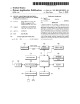
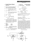
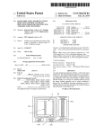
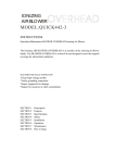
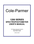
USOO8325218B2
(12) Unlted States Patent
(10) Patent N0.:
Oh et a].
(54)
US 8,325,218 B2
(45) Date of Patent:
COLOR SETTING APPARATUS AND
(56)
Dec. 4, 2012
References Cited
METHOD
U.S. PATENT DOCUMENTS
(75)
Inventors: Sang-Wook 0h, Ansan-si (KR);
7,116,317 B2 * 10/2006 Gregorio et al. ............ .. 345/184
Sung-Dae Cho, Yongin-si (KR);
7,405,729 B2 *
7/2008 Gregorio et al.
YmmngJmmg&Wmm?Km
75@JUIQ*
wmw QQMmmmHH
7,751,085 B2 *
7/2010
’
_
(73)
_
345/184
.HMym4
Yabe ............................ .. 358/19
FOREIGN PATENT DOCUMENTS
Asmgnee: Samsung Electronlcs C0., Ltd.,
.
JP
07_099589
4/1995
Samsung-ro, Yeongtong-gu, Suwon-51,
JP
13045527
20001
Gyeonggl-do (KR)
KR
2005-0077209
8/2005
OTHER PUBLICATIONS
(*)
(21)
Notice;
Subject to any disclaimer, the term Ofthis
patent is extended or adjusted under 35
LCD Digital Color TV User Manual, SONY Corporation 2005*
WWWAHYChm‘OIn, 0“ 13, 2011~*
U.S.C. 154(b) by 1363 days.
* Cited by examiner
Appl. No.: 11/652,330
Primary Examiner * David Eng
(74) Attorney, Agent, or Firm * Cha & Reiter, LLC
(22) Filed:
(65)
Jan. 11, 2007
(57)
Prior Publication Data
US 2007/0188666 A1
Au 1 6 2007
g'
(30)
’
a color setting controller for displaying a closed curve band
Foreign Application Priority Data
]an_ 27’ 2006
ABSTRACT
A color setting apparatus and method for a system for repro
ducing multimedia data are provided. The apparatus includes
(KR) ______________________ __ 10_2006_0008948
(51) Int CL
divided into at least two equal-sized sections each containing
a different color, and a setting band having at least two sec
tions for indicating change of a set value of each of the colors
on a screen, and for changing the set value of a selected color
and displaying the changed color according to the changed set
(52)
H04N1/60
(200601)
US. Cl. ........................................ ..
value on the screen. The color setting controller increases or
decreases the Size Of the semen for indicating Change Ofthe
(58)
Field of Classi?cation Search ................... .. 348/29
56‘ value accordmg ‘0 the set value
See application ?le for complete search history.
12 Claims, 8 Drawing Sheets
Yillll
Em
BOO
304a
3088
306
308b
)
304D
US. Patent
Dec. 4, 2012
Sheet 1 0f8
US 8,325,218 B2
FWCB. 1
100
/
KEY PAD
1/10
CONTROLLER
120
/
DISPLAY
130
/
STORAGE
‘1 50
US. Patent
Dec. 4, 2012
Sheet 2 0f 8
ozEnawm
EmoHwa“629.510 Ex
oz
US 8,325,218 B2
US. Patent
iDec.4,2012
US 8,325,218 B2
Sheet30f8
FIG. 3A
YMIH
304a
)
3088
3 O6
308b
304b
FIG. BB
304a
308c
306
308d
304b
US. Patent
Dec. 4, 2012
Sheet 4 0f8
YIIIH
304a
US 8,325,218 B2
[E]
310a
306
31Gb
304b
FIG. 3D
Ynll'
304a
3100
@
306
310d
304b
US. Patent
Dec. 4, 2012
Sheet 5 0f8
US 8,325,218 B2
FIG. 4
400
/
KEY PAD
410
/
420
/
DISPLAY
CONTROLLER
430
/
STORAGE
1
60
US. Patent
Dec. 4, 2012
US 8,325,218 B2
Sheet 6 0f 8
FIG. 5A
I
$500
IS
KEY BUTTON
NO
SELECTED?
YES
3502
SET CURRENT STATE TO
COLOR SETTING STATE
S504
YES
POINTER MOVING
COMPLETION KEY
$510
\
SET CURRENT STATE TO
POINTER MOVABLE STATE
PERFORM
OPERATION OF
CORRESPONDING
KEY
S512
NO
END KEY
SELECTED?
YES
END
US. Patent
Dec. 4, 2012
Sheet 7 0f8
US 8,325,218 B2
FIG. 5B
8518
MOVE POINTER ACCORDING
TO DIRECTIONAL KEY
CHECK CURRENT
LOCATION OF POINTER
INCREASE SET VALUE
DECREASE SET VALUE
I
I
(a)
US. Patent
Dec. 4, 2012
Sheet 8 0f8
FIG. 6
US 8,325,218 B2
US 8,325,218 B2
1
2
COLOR SETTING APPARATUS AND
METHOD
are arranged on-screen so that the set value of the color
selected from the arrangement can then be adjusted or
changed.
CLAIM OF PRIORITY
SUMMARY OF THE INVENTION
This application claims the bene?t under 35 U.S.C.
§119(a) from an application entitled “COLOR SETTING
APPARATUS AND METHOD,” ?led in the Korean Intellec
tual Property Of?ce on 27 Jan. 2006 and assigned Serial No.
10-2006-0008948, the entire contents of which are incorpo
rated herein by reference.
It would desirable to, instead, display, for user selection,
the settable colors, and to provide for selection and then
change of the set value of the selected color.
It would be further desirable, from the standpoint of user
convenience, to avoid having to repeat the entire procedure
for each color whose setting is to be adjusted.
The present invention provides a color setting apparatus
BACKGROUND OF THE INVENTION
and method in which selection of a color to be set and adjust
ment of its set value can be performed simultaneously.
In a ?rst aspect of the present invention, a color setting
apparatus includes a color setting controller for displaying a
1. Field of the Invention
The present invention relates to a color setting apparatus
and method for reproducing multimedia data.
2. Description of the Related Art
Development of multimedia technology has resulted in the
introduction of various kinds of multimedia data and the
closed curve band divided into at least two equal-sized sec
20
development of image reproduction systems for reproducing,
value of each of the colors on a screen, and for changing the
i.e., playing back or presenting, multimedia data.
set value of a selected color and displaying the changed color
Representative image reproduction systems for reproduc
according to the changed set value on the screen.
ing multimedia data include a digital television, a digital
camera, a digital camcorder, a mobile terminal, and so on.
25
An image reproduction system can reproduce various
The color setting controller may, according to the set value
desired, increase or decrease the size of the section for indi
cating change of the set value.
The setting band may be arranged within the closed curve
band.
In a second aspect, a color setting apparatus for a system for
types of multimedia data in various environments, and the
user can often set a color in which the multimedia data is to be
played back based on what is suitable within the ambient
environment.
tions each containing a different color, and a setting band
having at least two sections for indicating change of a set
30
reproducing multimedia data includes: a display for display
For example, when the image reproduction system repro
ing a closed curve band divided into at least two equal-sized
duces multimedia data in an environment where the screen of
sections each containing a different color, a setting band
having at least two sections for indicating change of a set
value of each of the colors, and a reference point for color
the image reproduction system is brighter than the ambient
light, color of the multimedia data to be played back on the
screen of the image reproduction system can be set to faith
35
fully represent what is intended.
If, on the other hand, the image reproduction system plays
direction in response to a request for rotating the closed curve
band and the setting band, changing the size of a portion of the
back multimedia data in an environment where ambient light
is brighter than the screen, color of the multimedia data repro
duced cannot be faithfully represented and the multimedia
setting band corresponding to a color located at the reference
40
data are, as a result, difficult to see.
To resolve this problem, the image reproduction system
provides a color setting function for adjusting the color of the
screen in dependence upon the ambient environment.
The image reproduction system displays settable colors on
45
the screen, which the user can set or adjust by means of the
color setting function.
point in response to a color change request, and displaying the
result.
The color setting apparatus may further comprise a key pad
which has at least one rotation key for rotating the closed
curve band and the setting band and at least one change key
for changing the size of a portion of the setting band corre
sponding to a color requested to be changed.
In a third aspect, a color setting apparatus includes: a
display for displaying a closed curve band divided into at least
two equal-sized sections each containing a different color, a
For example, the image reproduction system may display
on-screen, e. g., in bar graph form, a set value (e.g., brightness
of color) which is adjustable, and then displays the color
selection on a screen; and a color setting controller for rotat
ing the closed curve band and the setting band in a requested
50
setting band having at least two sections for indicating change
corresponding to the adjusted set value while the user sets or
of a set value of each of the colors, and a pointer which is
adjusts the set value.
The set value displayed in bar graph form has a maximum
movable on the closed curve band for color selection on a
screen; and a color setting controller for moving a location of
the pointer to a requested location on the closed curve band in
value and a minimum value for a certain color, and the set
value of the currently selected color is displayed together with
the bar graph.
55
color on the closed curve band at which the pointer is located
However, far more colors can actually be used for repro
duction of the multimedia data than can be adjusted using the
color setting function.
For example, when the image reproduction system
response to a location change request of the pointer, changing
the size of a section of the setting band corresponding to the
in response to a color change request, and then displaying the
result.
60
The color setting apparatus may further comprise a key pad
employs a 24-bit RGB color space for reproduction of the
which has at least one location change key for changing a
multimedia data, 16,777,216 (:28(R)><28(G)><28(B)) colors
location of the pointer on the closed curve band and at least
are usable in reproducing the multimedia data on the display.
one setting band section change key for changing the size of
However, since the image reproduction system provides
the section of the setting band corresponding to a color
the color setting function for only a limited number of colors,
65
requested to be changed.
the user may not be able to adjust a desired color. Typically,
In a fourth aspect, a color setting method for a system for
the colors which can be changed by the color setting function
reproducing, i.e., replaying, multimedia data, includes: (a)
US 8,325,218 B2
4
3
displaying a closed curve band divided into at least two equal
FIG. 6 shows a color setting interface screen used for color
setting according to the second exemplary embodiment of the
present invention.
sized sections each containing a different color, and a setting
band having at least two sections for indicating change of a set
value of each of the colors on a screen; and (b) changing the
set value of the selected color and displaying the changed
color according to the changed set value.
DETAILED DESCRIPTION OF EXEMPLARY
EMBODIMENTS
Step (b) may comprise increasing or decreasing the size of
the section for indicating change of the set value according to
the set value and displaying the result.
Hereinafter, exemplary embodiments of the present inven
tion are described in detail with reference to the accompany
In a ?fth aspect, a color setting method for a system for
ing drawings. The following discussion omits, for concise
reproducing multimedia data, includes: displaying a closed
ness and clarity of presentation, detailed description of
known functions and con?gurations incorporated herein.
FIG. 1 shows an exemplary color setting apparatus 50
curve band divided into at least two equal-sized sections each
containing a different color, a setting band having at least two
sections for indicating change of a set value of each of the
according to a ?rst embodiment of the present invention. The
colors, and a reference point for color selection on a screen;
rotating the closed curve band and the setting band in a
requested direction in response to a request for rotating the
closed curve band and the setting band; and changing the size
of a portion of the setting band corresponding to a color
located at the reference point in response to a color change
color setting apparatus 50 has a key pad 100, a controller 110,
a display 120, and a storage unit 130.
The key pad 100 has at least one key, generates a key
selection signal when a key is selected, and provides it to the
20
controller 110.
25
Right, left, up and down directional keys, and an end key
for terminating a current operation of the color setting appa
ratus 50, may be provided.
The controller 110 displays, through the display 120, a
color setting interface 300 used for reproduction of the mul
timedia data at a color setting request.
As shown in FIG. 3A, the color setting interface 300 com
prises a color circle 301 having at least one changeable color,
the different cross-hatchings and other designs in sectors of
30
the circle denoting respective colors. The color setting inter
request and then displaying the result.
In a sixth aspect, a color setting method for a system for
reproducing multimedia data involves: displaying a closed
curve band divided into at least two equal-sized sections each
containing a different color, a setting band having at least two
sections for indicating change of a set value of each of the
colors, and a pointer which is movable on the closed curve
band for color selection on a screen; moving a location of the
pointer to a requested location on the closed curve band in
response to a location change request of the pointer; and
changing the size of a section of the setting band correspond
ing to the color on the closed curve band at which the pointer
is located in response to a color change request and then
face 300 further includes a setting circle 302 arranged in the
color circle 301 to indicate change of the color contained in
the color circle according to the set value, and left and right
arrows 304a. 3041) indicating left and right movement direc
displaying the result.
35
120.
As seen from FIG. 3A, the color circle 301 has four change
A more complete appreciation of the present invention, and
many of the attendant advantages thereof, will be readily
apparent as the present invention becomes better understood
tions of the color circle. The setting circle 302 centers on a
color setting reference point 306 of the screen of the display
BRIEF DESCRIPTION OF THE DRAWINGS
40
by reference to the following detailed description when con
sidered in conjunction with the accompanying drawings, in
able colors. The setting circle 302 shows the initial set values
of the four colors, and indicates a change of the corresponding
color according to the set value of each of the four colors.
As an example, FIGS. 3A, 3D show, by way of illustrative
which like reference symbols indicate the same or similar
and non-limitative example, the color setting interface 300
components, wherein:
displayed on the screen of the display 120.
FIG. 3A shows four colors, but the number of colors is not
FIG. 1 is a block diagram illustrating a color setting appa
ratus according to a ?rst exemplary embodiment of the
45
so limited.
present invention;
FIG. 2 is a ?owchart illustrating a color setting method of
the color setting apparatus according to the ?rst exemplary
embodiment of the present invention;
As shown in FIG. 3A, the color setting interface comprises
50
a color circle 301 having at least one changeable color, the
as shown in FIG. 3A.
different cross-hatchings and other designs in sectors of the
In that state, it is preferably the key selection signal corre
circle denoting respective colors. The color setting interface
further includes a setting circle 302 arranged in the color
circle 301 to indicate change of the color contained in the
color circle according to the set value, and left and right
arrows 304a. 3041) indicating left and right movement direc
sponding to the up directional key which serves as a signal for
55
selection signal corresponding to the down directional key
serves as a signal for increasing the magnitude of the set value
60
FIG. 4 is a block diagram illustrating a color setting appa
ratus according to a second exemplary embodiment of the
present invention;
method of the color setting apparatus according to the second
exemplary embodiment of the present invention; and
of the color located at the color setting reference point 306.
The roles of the up and down keys may, however, be reversed
in this regard.
FIGS. 3A, 3B collectively demonstrate, operationally, a
transition in the color setting interface 300. For example,
120.
FIGS. 5A and 5B are ?owcharts illustrating a color setting
reducing the magnitude of the set value of the color located at
the color setting reference point 306; conversely, the key
tions of the color circle. The setting circle 302 centers on a
color setting reference point 306 of the screen of the display
The controller 110 changes and then displays the set value
of the color located at the color setting reference point 306.
This is done in response to a key selection signal correspond
ing to actuation of the up -down directional key on the key pad
100 in a state in which the color setting interface is displayed
when the controller 110 decreases a magnitude of the set
65
value for a color 30811 by keypad 100 operation, the sector
308b shrinks in size correspondingly to arrive at sector 308d.
As this occurs, the color 308a located at the color setting
US 8,325,218 B2
6
5
If the selected key is the left directional key (S210), the
reference point 306 is changed to a color 3080 corresponding
to the decreased magnitude of the set value.
color circle and the setting circle are rotated counterclock
The controller 110 rotates the color circle 301 and the
setting circle 302 in a direction corresponding to each direc
wise (S212).
tional key, as a key selection signal corresponding to the
When the selected key is not the left directional key, the
color circle and the setting circle are rotated clockwise
right-left directional keys is input from the key pad 100 in a
(S214).
state in which the color setting interface of FIG. 3B is dis
If the selected key is determined not to be the right-left
directional key, query is made as to whether the selected key
played.
The controller 110 changes and then displays the set value
of the color located at the color setting reference point 306
is the up directional key (S216).
If it is the up directional key, the set value of the color
located at the color setting reference point is decreased by a
according to the key selection signal corresponding to the
up-down directional key input from the key pad 100. The
predetermined magnitude (S218). In addition, the size of the
change in set value is preferably concurrent with the respec
corresponding sector or portion of the setting circle is like
tive change in color, and they preferably occur continuously.
wise decreased (S220).
These changes occur in a state in which the color circle 301
and the setting circle 302 have been rotated in a direction
When the selected key is determined not to be the up
directional key in step S216, the set value of the color located
at the color setting reference point is increased by a predeter
mined magnitude (S222), and the sector of the setting circle is
corresponding to which of the right-left directional keys is
actuated. The up-down adjustment may be held inoperative
until the rotating achieves one of the designated, here four,
orientations.
The key selection signal corresponding to the left direc
20
FIG. 4 is a block diagram illustrating an exemplary color
setting apparatus 60 according to a second embodiment of the
tional key may cause rotation of the color circle 301 and the
setting circle 302 counterclockwise, and the key selection
signal corresponding to the right directional key may cause
25
rotation of the color circle 301 and the setting circle 302
clockwise.
That is, the controller 110 rotates the color circle 301 and
the setting circle 302 counterclockwise by a predetermined
angle as the key selection signal corresponding to the left
directional key is input from the key pad 100 in a state in
which the color setting interface of FIG. 3B is displayed, as
shown in FIG. 3C.
Conversely, the controller 110 increases a magnitude of the
set value of the color 310a located at the color setting refer
ence point 306 by a predetermined amount as the key selec
30
60 additionally features an end key for terminating a current
35
40
evidenced by the expansion in sector size, as seen by com
45
select the color. As shown in FIG. 6, the pointer 604 may
50
(S202), query is made as to whether the selected key is the
right-left directional key (S208).
appear on-screen as a highlighting that frames the current
section 606a, 608a, 610a, 61211 of the color band 601,
although the pointer may instead take another form, such as a
cursor displayed as an arrow.
In the color setting interface of FIG. 6, the color band 601
55
contains four colors, and the sectorized setting magnitude
indicator 602 contains four respective portions, although
more or fewer colors/portions are within the intended scope
of the invention.
As in the ?rst embodiment, the compact design of the color
(S202).
end key, if the selected key is not the directional key (S204).
If the selected key is not the end key, an operation is
performed (S206); otherwise, if the selected key is the end
key, the current operation is ?nished.
If the selected key is determined to be the directional key
sectors corresponds to an associated segment or section 606a,
604 which is movable on the color band 601 and is used to
played at a color setting request (S200).
The color setting apparatus checks, when a certain key is
selected, whether or not the selected key is the directional key
A check is made as to whether or not the selected key is the
able color for reproduction of the multimedia data, and the
sectorized setting magnitude indicator 602 which contains
portions or sectors that track and indicate, according to the set
value, change in the associated color of the color band 601. In
the exemplary con?guration seen in FIG. 6, each of the four
608a, 610a, 612a ofthe color band 601.
The color setting interface 600 further comprises a pointer
The storage 130 stores at least one color set value selected
apparatus 50 according to the ?rst embodiment of the present
invention.
The color setting apparatus 50 checks whether or not a
certain key is selected in a state in which the color setting
interface 300 used to reproduce the multimedia data is dis
The pointer is described further below.
The controller 410 displays the color setting interface used
for reproduction of multimedia data through the display 420
at a color setting request.
As shown in FIG. 6, the color setting interface 600 com
prises a color band 601 which contains at least one change
paring sectors 310b, 310d in FIGS. 3C, 3D, respectively.
by the user.
FIG. 2 describes a color setting method of the color setting
provides the key selection signal to the controller 410.Among
the keys are right, left, up and down directional keys.
Unlike the ?rst embodiment, the cooler setting apparatus
operation of the color setting apparatus, a pointer moving
completion key, and a color setting completion key.
number of discrete key actuations. The magnitude change is
As shown in FIG. 3D, the color located at the color setting
reference point 306 is consequently changed to a color 310c
corresponding to expanded magnitude of the set value.
present invention.
As in the ?rst embodiment, the color setting apparatus 60
comprises a key pad 400, a controller 410, a display 420, and
a storage unit 430. The key pad 400 has at least one key,
generates a key selection signal when a key is selected, and
tion signal corresponding to the down directional key is input
from the key pad 100 in a state in which the color setting
interface of FIG. 3C is displayed. The predetermined amount
may be, for example, proportional to the amount of time the
down directional key is pressed, or may correspond to the
likewise expanded in size (S224).
60
setting interface 600 is particularly suited to the screen of the
display 420.
Unlike the ?rst embodiment, however, the directional keys
65
are implemented as multi-function keys. Depending upon the
current state, they either move the pointer 604 in a particular
direction or adjust upward/ downward a setting value.
In particular, when the pointer 604 moves on the colorband
601 of the color setting interface displayed as shown in FIG.
US 8,325,218 B2
8
7
6, the controller 410 allows the pointer 604 to move according
If the current state is the pointer movable state, the pointer
to the directional key selection signal input from the key pad
604 is moved in a direction corresponding to the directional
400.
When the pointer 604 does not move on the color band 601,
key selected (8518).
The color setting apparatus 600 checks a current location
of the pointer 604 on the color band 601 when it is not in the
the controller 410 perceives a location of the pointer 604 and
increases or decreases the set value of the color at which the
pointer movable state (8520).
The color setting apparatus 600 checks whether the pointer
pointer 604 is located according to the directional key selec
tion signal input from the key pad 400. In a manner similar to
that of the ?rst embodiment, when the pointer 604 is located
604 is located at an upper part of the color band 601 (8522).
Here, when a user looking at the screen or display 420 of
at the lower section 60611 of the color band 601, increase of the
set value is not only visible from the change in color for that
the color setting apparatus 60 displaying the color setting
interface 600 can see that the pointer 604 is positioned in an
lower section, but, perhaps more conspicuously, by an expan
sion in size of the sectorized setting magnitude indicator
60612.
More generally, the second embodiment operates as fol
lows. The controller 410 sets the current state to a color
setting state when a key selection signal corresponding to the
pointer moving completion key is input from the key pad 400
in a state in which the color setting interface is displayed as
shown in FIG. 6.
20
Conversely, the controller 410 sets the current state to a
pointer movable state in which the pointer is movable on the
color band 601 when a key selection signal corresponding to
upper part of the color band 601, the pointer is located at the
upper part of the color band.
For example, as shown in FIG. 6, when the pointer 604 is
located in the section of a color 610a, it is located in the upper
part of the color band 601.
The color setting apparatus 60 checks whether the up direc
tion key is selected when the pointer is located at the upper
part of the color band 601 ($524).
The color setting apparatus 60 increases and then displays
the set value of the color at which the pointer 604 is located
when the up directional key is selected in a state in which the
pointer is located at the upper part of the color band 601
the color setting completion key is input from the key pad 400
The controller 410 ?nishes the current operation as a key
($526). This change in set value is preferably accompanied
not only by continuous transition in the color displayed in the
upper part of the color band 601, but by change in size of the
selection signal corresponding to the end key is input from the
respective sectorized setting magnitude indicator 61019. The
in a state in which the color setting interface of FIG. 6 is
25
displayed.
key pad 400 in a state in which the color setting interface of
FIG. 6 is displayed.
30
The color setting apparatus 60 checks whether the down
directional key is selected when the up directional key is not
The storage unit 430 stores at least one color set value
selected by the user.
As shown in FIG. 6, the color band 601 of the color setting
interface 600 contains four colors, and the pointer 604 is
located on the color section 60611 of the color band. Although
four sections 606a, 608a, 610a, 61211 are shown, fewer or
selected in a state in which the pointer is located at the upper
35
part of the color band 601 ($528).
The color setting apparatus 60 decreases and then displays
the set value of the color at which the pointer 604 is located
when the down directional key is selected in a state in which
the pointer is located at the upper part of the color band 601
more sections are within the intended scope of the invention.
FIGS. 5A and 5B are ?owcharts illustrating an example of
a color setting method of the color setting apparatus 60 of the
second embodiment of the present invention.
same visible phenomena occur in each of the below-speci?ed
cases, and will not be further described herein below.
($530).
40
The above-shown logic for increasing or decreasing a set
value is extended by, in the event the pointer is not located in
the upper part, checking ?rst whether it is located in the lower
part (8532) and, if not located there, whether it is located in
the left part (8542). If the latter check and if it is not located
45
If it is not the directional key, query is made on whether the
in the left part, the right part is assumed (8542, “NO” branch).
Accordingly, the steps $524-$530 performed in the above
selected key is the pointer moving completion key (8504).
If the selected key is pointer moving completion key, the
described manner in the case of the pointer 604 being located
in the upper part, are analogously performed as steps $534
As shown in FIGS. 5A, SE, a check is made as to whether
a key is selected in a state in which the color setting interface
600 is displayed at a color setting request ($500).
When a key is selected, query is made as to whether the
selected key is the directional key (8502).
color setting apparatus 60 goes into the color setting state for
setting the color of the color band section 606a, 608a, 610a,
61211 at which the pointer is current located ($506).
SS40, 8544-8550, and 8552-8558, correspondingly, in
50
The selected key is not the pointer moving completion key,
a check is made as to whether the selected key is the color
setting completion key (8508).
If it is the color setting completion key, the color setting
55
apparatus 60 goes into the pointer movable state in which the
pointer is movable on the color band 601 ($510).
If, on the other hand, it is not the color setting completion
key, the color setting apparatus 60 checks whether the
selected key is the end key (8512).
dependence upon where the pointer is located. In each of the
four possibilities of where the pointer is located, after the
respective set value adjustment routine is executed, return is
made to the beginning of the process of FIG. 5A.
In particular, the color setting apparatus 60:
a) checks whether the pointer is located at a lower part of
the color band when the pointer is determined to not be at the
upper part of the color band in step $522 (8532);
b) checks whether the down direction key is selected when
the pointer is located at the lower part of the color band
60
When it is not the end key, the current operation that is
(8534);
c) increases and then displays the set value of the color at
which the pointer is located when the down directional key is
being invoked by the user is performed (8514); however, if it
is the end key, the currently performed operation ?nishes, i.e.,
selected in a state in which the pointer is located at the lower
halts.
part of the color band (8536);
d) checks whether the up directional key is selected when
If, to the contrary, a directional key is being selected
65
(8502), query is made on whether the current states is the
the down directional key is not selected in a state in which the
pointer movable state (8516).
pointer is located at the lower part of the color band ($538);
US 8,325,218 B2
10
e) decreases and then displays the set value of the color at
which the pointer is located when the up directional key is
band section is maintained, and the associated closed
curve band section changes color correspondingly.
2. The color setting apparatus of claim 1, wherein the color
setting controller is further operative to display a reference
selected in a state in which the pointer is located at the lower
part of the color band (8540);
f) checks whether the pointer is located on the left part of
point for color selection on a screen, to rotate the closed curve
the color band when the pointer is determined to not be on the
band and the setting band in a requested direction in response
to a request for rotating the closed curve band and the setting
band; and to change color located at the reference point cor
responding to the increase or, decrease in size of the given
lower part of the color band in step S532 (8542);
g) checks whether the left direction key is selected when
the pointer is located on the left part of the color band (8544);
h) increases and then displays the set value of the color at
which the pointer is located when the left directional key is
setting band section.
3. The apparatus of claim 2, further comprising:
selected in a state in which the pointer is located on the left
a key pad which has at least one rotation key for said
rotating and at least one change key to cause the color
changes in response to a request to change color.
4. The color setting apparatus of claim 1, wherein the color
part of the color band (8546);
i) checks whether the right directional key is selected when
the left directional key is not selected in a state in which the
pointer is located on the left part of the color band (8548);
j) decreases and then displays the set value of the color at
which the pointer is located when the right directional key is
setting controller is further operative to display a pointer that
is movable on the closed curve band for color change selec
tion of a section of the closed curve band, and to move a
selected in a state in which the pointer is located on the left
part of the color band (8550).
k) when the pointer is not located on the left of the color bar,
determines that the pointer is located on the right part of the
color bar and checks whether the right directional key is
20
5. The apparatus of claim 4, further comprising:
a key pad which has:
at least one location change key for navigating the
selected (8552);
1) increases and then displays the set value of the color at
location of the pointer to a requested location on the closed
curve band in response to a location change request.
25
pointer on the closed curve band; and
at least one setting band section change key to cause the
which the pointer 604 is located when the right direction key
is selected in a state in which the pointer is located on the right
increase or decrease in size.
part of the color bar (8554);
m) checks whether the left directional key is selected when
the right directional key is not selected in a state in which the
6. The color setting apparatus of claim 1, wherein the
closed curve band comprises an outer band of a circle.
30
pointer 604 is located on the right part ofthe color bar (8556);
and
n) decreases and then displays the set value of the color at
which the pointer 604 is located when the left directional key
is selected in a state in which the pointer is located on the right
7. The color setting apparatus of claim 1, wherein the
closed curve band comprises an outer band of a polygon.
8. A color setting method for a system for reproducing
multimedia data, comprising the acts of:
35
a) displaying:
a closed curve band divided into at least two equal-sized
part of the color bar (8558).
As described above, the color setting apparatus and method
can simultaneously select a color and adjust its set value.
While the present invention has been described with refer
ence to exemplary embodiments thereof, it will be understood
by those skilled in the art that various changes in from and
detail may be made therein without departing from the scope
of the present invention as de?ned by the following claims.
What is claimed is:
1. A color setting apparatus for a system for reproducing
sections in ?xed sectors, each containing a different
color and having a respective set value that is adjust
able to change the color; and
a setting band, having setting sections each for indicat
ing change in a respective set values and thereby
40
indicating an amount of color change in an associated
closed curve band section;
wherein the setting band is disposed within the closed
curve band and said setting band and closed curve
45
multimedia data, the apparatus comprising:
band are correspondingly sectorized in a ?xed manner
so that a given setting section resides within the same
sector as its associated closed curved band section;
and
a color setting interface; and
a color setting controller for displaying on said interface:
a closed curve band divided into at least two equal-sized
sections in ?xed sectors, each containing a different
color having a respective set value that is adjustable to
50
b) changing a set value indicated by a given setting section,
the given setting section indicating the change by an
change the color; and
a setting band having a number of setting sections, which is
equal to the number of said at least two equal-sized
sections, each for indicating change in a respective set
values and thereby indicating an amount of color change
increase or decrease in its size while the same sectorized
relationship with the associated closed curve band sec
tion is maintained, and the associated closed curve band
9. The color setting method of claim 8, further comprising
displaying a reference point for color selection;
of an associated closed curve band section,
wherein the setting band is disposed within the closed
curve band and said setting band and closed curve band
are correspondingly sectorized in a ?xed manner so that 60
a given setting section resides within the same sector as
its associated closed curved band section, and
wherein the amount of color change indicated by the given
setting section is represented by an increase or decrease
in a size thereof in correspondence with associated
adjustment in the respective set value, while the same
sectorized relationship with the associated closed curve
section changes color correspondingly.
55
rotating the closed curve band and the setting band in a
requested direction in response to a request for rotating
the closed curve band and the setting band; and
changing color located at the reference point in response to
a color change request.
10. The color setting method of claim 8, further compris
ing:
65
displaying a pointer which is movable on the closed curve
band for color change selection of a section of the closed
curve band; and
US 8,325,218 B2
11
moving a location of the pointer to a requested location on
the closed curve band in response to a request for loca-
12
12. The color setting method of claim 8, Wherein the closed
curve band comprises an outer band of a polygon.
tion change of the pointer.
11. The color setting method of claim 8, Wherein the closed
curve band comprises an outer band of a circle.
*
*
*
*
*
UNITED STATES PATENT AND TRADEMARK OFFICE
CERTIFICATE OF CORRECTION
PATENT NO.
: 8,325,218 B2
APPLICATION NO.
: 11/652330
: December 4, 2012
: Sang-Wook Oh et a1.
DATED
INVENTOR(S)
Page 1 Ofl
It is certified that error appears in the above-identi?ed patent and that said Letters Patent is hereby corrected as shown below:
In the Claims
Column 9, Claim 1, Lines 55-56 should read as follows: --...respective set value and thereby...Column 10, Claim 2, Line 9 should read as follows: --...to the increase or decrease in...-
Column 10, Claim 8, Line 39 should read as follows: --...respective set value and thereby...-
Signed and Sealed this
Twenty-third Day of April, 2013
Teresa Stanek Rea
Acting Director 0fthe United States Patent and Trademark O?ice