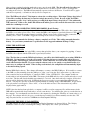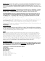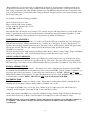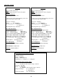
1
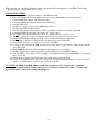
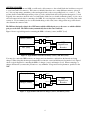
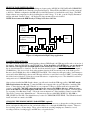
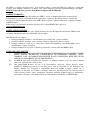
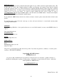
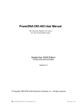
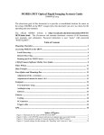
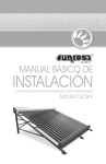
TM
Products
TM
User’s Manual
www.BNBPRODUCTS.com
Thank you for purchasing the BNB Products, Digital Power Recorder (DPR)!
If you did not make your purchase directly through BNB Products, please take a few moments to register with
us so we can notify you of any product or software updates and changes. You may register online with us at
www.bnbproducts.com or complete the form below and mail it to us. Your privacy is important to us. We do
not make any of the information you provide available to others except for purchase and order fulfillment. We
will not put you on any mailing lists.
-------------------------------------------------------------------------------------------------------------------------------
BNB Products - Purchase Registration Form
Mail To:
BNB Products
#284
906 W. McDermott Dr., Ste 116
Allen, TX 75013
Date: ____________________________________________
Name: ___________________________________________
Email: ___________________________________________
Street Address: ____________________________________
City, State, zip: ____________________________________
Product(s) Purchased: _______________________________
_________________________________________________
_________________________________________________
Purchased From: ___________________________________
Comments: _______________________________________
_________________________________________________
_________________________________________________
_________________________________________________
_________________________________________________
i
CONTENTS
1. Introduction
1. Key Features
1. Package Contents
1. System Requirements
2. Hardware
3. Quick Start Steps
4. Getting Started
5. High Voltage Configuration
5. Loading the DPR Software
5. Changing the DPR Recording Parameters
6. Recording Missions
7. Using the USB Connection While Recording (Bench Testing)
7. Using the Software
7. Graphing the Data
7. Changing the Display Parameters
8. Saving the Data
8. How to Zoom
8. Statistics Window
9. Time Specific Statistics
9. Adding Notes to Missions
9. Manual Memory Clear
9. Estimating Recording Time
10. Specifications
11. Warranty
12. Return Policy
12. Support
ii
INTRODUCTION
The BNB Products Digital Power Recorder (DPR) is a powerful, lightweight, and compact module for tracking and
recording the vital data you need while using your electric powered radio controlled (R/C) device – such as R/C cars
and aircraft. It allows you to retrieve and record actual in-use performance data of your electric setup, which may be
downloaded to your computer via the supplied USB interface cable to graph the recorded data.
Two DPR units are currently available:
The DPR–50 handles up to 30 Volt input, and up to 50 Amp current load
The DPR–100 handles up to 30 Volt input, and up to 100 Amp current load
This manual is used for both models.
KEY FEATURES
- Very small: 1.2 inches X 1.6 inches
- Very lightweight: Approximately 0.9 ounces (25 grams)
- Accepts wide range of Voltage inputs: 7 to 30 Volts (0 to 30 Volts with USB connected)
- Digitally records up to 9+ hours of mission data
- Over sampling rate: Approximately 5,000 samples per second per channel
- Records and graphs in-use
Current load up to 50 Amps (up to 100 Amps with the DPR–100)
Battery Voltage from 7 to 30 Volts (0 to 30 Volts with USB connected)
Power output up to 1500 Watts (up to 3000 Watts with the DPR–100)
Amount of charge used (mAh)
Battery Efficiency
Elapsed time of each mission
Temperatures from dual temperature probe or temperature probe / LED alert indicator *
- Configurable
Data sampling rate (1-50 samples per second per channel)
Data recording resolution
Recording trigger
Channels to record
Computer graphed displays with the powerful DPR-Graph software provided
- Very easy to set up and use
PACKAGE CONTENTS
Digital Power Recorder (DPR-50 or DPR-100)
3 foot USB-A to mini-B cable
CD-ROM containing powerful graphing software (DPR-Graph) and soft version of manual
Jumper for manual memory clear
Hard copy of user’s manual
SYSTEM REQUIREMENTS
- PC with one of the following operating systems:
Windows 2000, Windows XP
- CD-ROM drive (or access to the internet)
- Available USB port
- 2 Megabytes hard drive space
* Optional dual temperature probes (TMP-2), temperature probe / LED alert indicator (TMP-LED), or 6 foot
USB-A to mini-B cable (USB-6) may be purchased separately.
1
HARDWARE
Figure 1 shows the Digital Power Recorder (DPR)
The primary parts of the DPR are as follows:
- 2 Red (+) and 2 Black (-) wire leads on one side of the board - for
connection to the power source and load.
- One 4-pin connector - for connection to the optional accessories or manual memory clear feature.
- One mini USB connector - for connection to computer.
- 2 LED’s - to indicate the power status, recording status,
recording time remaining and self diagnostics (Error).
Red/Black pairs to
Source and Load
Black leads (-)
Red leads (+)
4-pin connector for optional
accessories or jumper for manual
memory clear.
USB connector to computer
Figure 1: The Digital Power Recorder (DPR)
2
Please note that you should read and understand this entire manual before attempting to use the DPR. The following
“Quick Start Steps” should be used only as a guide.
QUICK START STEPS
1. Add the proper source and load connectors to the DPR wire leads.
2. Remove the jumper from the 4-pin header connector (used for manual memory clear-discussed later).
3. Load the DPR-Graph software and USB support files.
4. Connect the DPR to the computer with the proper USB cable.
5. Install the USB driver.
6. The DPR is now able to connect to the DPR-Graph software.
7. Disconnect the DPR from the computer.
8. Turn all power settings (such as throttle) to OFF on your R/C craft before connecting to the DPR.
9. Connect the DPR to the load (ESC) first, then power source (battery).
10. The red LED should quickly flash twice to show it is getting power and is ready to record.
11. The DPR is factory set to begin recording five seconds after it is connected to a power source.
12. The green LED will light when the recording mode is activated and during recording mode.
13. After you have completed recording a mission, disconnect the power from the DPR.
14. To record another mission, reconnect a power source to the DPR.
15. To view the data, disconnect the DPR from the power source and load, and connect it to the computer with the
proper USB cable.
16. Run the DPR-Graph software. It should appear as an airplane icon on your desktop.
17. The DPR-Graph software will automatically search the COM ports for the DPR and connect.
18. Click “Get Data”. The software will now attempt to download the mission data from the DPR. This will take
about 3-5 seconds.
19. After the mission data has been downloaded, all recorded missions will be displayed.
20. You can now analyze the data, view any or all missions, change the display parameters, zoom in, view timespecific (or overall) statistics, add notes, and save the mission data.
CAUTION: The DPR–50 and DPR–100 are capable of measuring up to 30 Volts input at 50 or 100 Amps
respectively. Working with high Voltage and Current levels can be very dangerous, or lethal. Necessary safety
precautions must be taken when working with high power.
3
GETTING STARTED
Before you begin using your new DPR, you will need to add connectors to the red and black wire leads that correspond
to your source and load connectors. These were not included since there are so many different connector options in
use. It is very important to match the positive and negative leads to the corresponding leads (+ to + and - to -). The
red wire leads from the DPR represent the positive (+) leads, and the black wire leads represent the negative (-) leads.
Typically, the connections should be red-to-red and black-to-black, but you should confirm the polarity of your source
and load connection leads before connecting to the DPR. It is very important to make strong, solid solder joints on the
connectors. We recommend you also use heat shrink tubing on the solder joints to help prevent any possible electric
short between the connector leads.
The DPR was designed so that it does NOT matter which red/black pair goes to the source or which red/black
pair goes to the load. The DPR circuitry automatically detects the source and load.
Figure 2 shows a typical diagram for connecting the DPR to a battery (source) and ESC (load).
Battery (source)
ESC (load)
+
Red (+)
--
Black (-)
+
Red (+)
--
Black (-)
DPR
Digital Power
Recorder
Figure 2: Typical DPR connection to battery (source) and ESC (load).
You may also connect the DPR between your charger and your batteries to analyze how the batteries are being
charged. When doing this, the charger automatically becomes the source and the batteries become the load. Figure 3
shows a typical diagram for connecting the DPR to a charger (source) and batteries (load). When connecting to a
charger and batteries you must take precautions to stay within the Voltage and Current parameters specified for the
DPR.
Battery (load)
Charger (source)
+
Red (+)
--
Black (-)
+
Red (+)
--
Black (-)
DPR
Digital Power
Recorder
Figure 3: Typical DPR connection to charger (source) and battery (load).
4
HIGH VOLTAGE CONFIGURATION
For advanced, high Voltage configurations utilizing two battery packs (OF EQUAL VOLTAGE AND CHEMISTRY)
wired in series, the DPR can be connected as displayed in Figure 4. This will allow the DPR to be used in systems up
to 60 Volts. With this configuration the DPR will record the full Current load, and half the total Voltage. The DPRGraph software can compensate for this by doubling the recorded Voltage. To do this, open the “Display Parameters”
window and check “Double Voltage”. All displayed Voltage amounts will now be doubled.
NOTE: Do not connect the DPR directly to Voltage levels above 30 Volts.
Battery 1:
Up to
7s Lipo
-+
Battery packs must be
of equal Voltage and
chemistry.
Battery 2:
Up to
7s Lipo
--
ESC
DPR
+
--
--
--
+
+
+
Figure 4: Configuration for High Voltage applications
LOADING THE SOFTWARE
The DPR CD-ROM includes the powerful graphing software (DPR-Graph), the USB support files and a soft version of
this manual. Insert the DPR CD into the CD-ROM drive. If you do not have a CD-ROM drive, you may download
the software, USB support files and DPR manual on the World Wide Web at www.bnbproducts.com. Follow
the on-screen instructions to download. The CD should automatically begin to load when inserted into the computer’s
CD-ROM drive. If it does not load, click on the start/run selections at the bottom left corner of the desktop screen.
Browse to the CD-ROM drive, click on DPR-SETUP and RUN. The software should begin loading. It will attempt to
create and load the DPR-Graph software and USB support files into a new folder located at C:\DPR. You may change
this folder location if desired. Follow the on-screen instructions to complete the process. The default file location for
saving missions is C:\DPR\MISSION FILES.
After you have installed the DPR-Graph software, you will need to install the USB support files. DO NOT run the
DPR-Graph software for this step. Connect the DPR to the computer with a proper USB cable to install the USB
driver. Connect the large end of the USB cable to your computer’s USB port, and the small end to the mini USB
connector on the DPR. DO NOT connect an external power source to the DPR for this step. All the necessary
power to the DPR is received through the USB cable. After connecting the DPR to the computer, a window should
pop up stating “New Hardware Found”. Follow the onscreen instructions. If the installation cannot locate the USB
support file, you may select “Manual Browse”. The necessary files are called DPR_2K.INF (for Win 2000) or
DPR_XP.INF (for Win XP). The default directory location is C:\DPR\USB SETUP FILES. The USB driver should
install, and can now connect to the DPR.
CHANGING THE DPR RECORDING PARAMETERS (optional)
The DPR is factory set to record missions when you receive it. It is not necessary to change the recording parameters
before you begin recording missions, but you have the ability to do so through the DPR-Graph software. There are
five recording options you may change. These options include the recording sampling rate, channels to record,
recording resolution, recording trigger, and LED alert, as described below.
5
Note: The settings for sampling rate, channels to record, and recording resolution directly affect the amount of
recording time available.
Recording Sampling Rate: The DPR is capable of recording data samples from 1 to 50 times per second. To achieve
longer recording times, set the samples-per-second to a lower sampling rate. To achieve more precise sampling (or for
shorter recording times), set the samples-per-second to a higher sampling rate. The DPR is factory set to record 4
samples-per-second, which should be adequate for most users.
Channels to Record: The DPR is capable of recording four base channels: Voltage, Current, Temp1 and Temp2.
Elapsed time is always recorded, and all other channels are calculated from one or more of these. Note: Current
must be set to record to view the charge used. Current and Voltage both must be set to record to view Power.
The DPR is factory set is to record the Voltage and Current.
Recording Resolution: The recording resolution sets the resolution of the channels being recorded. The resolution
mode can be set to “Standard” or “High” resolution. Setting the resolution to “High” will allow the DPR to record the
Current at 2x and Voltage at 4x the “Standard” resolution. The DPR is factory set at “Standard” resolution. To
activate “High Resolution”, check the box next to “High Resolution”.
Recording Trigger: The DPR recording trigger tells the DPR when to begin recording after it is connected to a power
source. It can be set to begin recording at the first current load (from 3 to 20 Amps), or at a specific elapsed time after
it is connected to a power source (from 2 – 129 seconds). The DPR is factory set to begin recording 5 seconds after it
is connected to a power source.
LED Alert Settings: The LED alert settings may be used with the optional temperature probe / LED Alert Indicator
(TMP-LED). You may select alert levels for Voltage, Current and/or temperature. When any of these are activated,
the LED probe will flash when the levels are reached.
To change any of the recording parameters, connect the DPR to the computer as previously explained and run the DPR
software. The software will attempt to connect to the DPR COM port. If it is unable to connect to the DPR, you can
manually select the COM port or “scan” in the “port” menu at the top of the screen. After connected, the screen will
display “Digital Power Recorder (DPR) found on COM port X”. Click the “Recording Parameters” button.
The software will attempt to download, and display, the current recording parameters from the DPR. You may change
any parameter, then click “Update” to set the new recording parameters. If the DPR is not connected, a message will
display stating “Not Connected to DPR”, all fields will be locked, and the last known values will be displayed.
Note: The DPR recording parameters may only be updated when the DPR memory is empty. If you attempt to
open the Recording Parameters window while the DPR still has missions stored, you will be instructed to clear
the stored data before updating is possible.
RECORDING MISSIONS
Make sure all control settings on your R/C device (such as throttle) are set to OFF. Connect the electronic speed
control (ESC) “load” first, then the power source (battery) to the DPR. Always connect the load first and the power
source last. Once the power is connected, the red LED will quickly flash twice to indicate it is getting power. It will
continue to flash, indicating how much recording time is remaining - one flash/pause (0% - 25% full), two
flashes/pause (26% - 50% full), three flashes/pause (51%-75% full), constant flashes (76% - 99% full), constant
on (100% full). When the LED is constant on, the memory is full, and it can no longer record additional data until the
stored data is uploaded to a computer or manually cleared using the jumper (discussed later).
After the DPR is connected to the “load” and power “source” and the recording is triggered, the green LED will light.
It is now recording. The DPR is factory set to begin recording five (5) seconds after power is connected. It will
continue to record data until the battery is discharged below 7 Volts, the power source is disconnected, or the memory
is full. The green LED will remain on until the recording is stopped.
6
After you have completed a mission, unplug the power source from the DPR. The data will not be lost when you
disconnect the power from the DPR. To record another mission, reconnect a power “source”, and trigger the
recording mode as before. The DPR will automatically separate each recorded mission. You will be able to graph
each mission separately, or all missions side-by-side for comparisons.
Note: The DPR needs at least 7 Volts input to activate the recording trigger. If the input Voltage drops below 7
Volts while recording, the data may become increasingly inaccurate or erratic. Because of this, the DPR is
programmed to go into “sleep” mode and stop recording if the input Voltage drops below 7 Volts (without the
USB connected). If this occurs, both LEDs will turn off and the power source must be disconnected to reset the
unit before continuing to record.
USING THE USB CONNECTION WHILE RECORDING (Bench Testing)
You may record the battery Voltage down to 0 Volts with the DPR if you connect the USB cable to the computer and
the DPR as a secondary power source. First, connect the DPR to the computer as previously discussed. The red LED
should flash to indicate the amount of memory available. When you are ready to begin recording, connect the “load”
then the power “source” to the DPR. Trigger the recording mode as before to begin recording.
Note: It is not recommended to discharge a battery completely to 0 Volts. This could permanently harm the
battery. See your battery manufacture’s specifications for the suggested minimum discharge Voltage.
USING THE SOFTWARE
GRAPHING THE DATA
Once you have acquired the data in the DPR, you may then upload the data to your computer for graphing. Connect
the DPR to the computer with the USB cable as previously described.
Note: The first time you run the DPR-Graph software, you will be asked which model you are using (DPR-50 or
DPR-100). It is important to select the correct model. Selecting the incorrect model will result in incorrect
Current graphs, Current trigger, and Current alerts. When a mission is saved, the model configuration is also
saved with the mission data file. If you are using the software only to view sample or saved mission files, it is
unnecessary to configure the model. When viewing saved missions, the configuration will automatically adjust
to the mission being opened.
Run the DPR-Graph software. The software will attempt to connect to the DPR COM port. If it is unable to connect
to the DPR, you may manually select the COM port or select “scan” from the “Port” menu at the top of the screen.
After connected, the screen will display “Connected to DPR”. Select “GET DATA”. The computer should now
download the stored information from the DPR. The memory in the DPR will also now be cleared and ready to record
more data. The data will download within approximately 3-5 seconds. Once the download is complete, all recorded
missions will be displayed side-by-side. If multiple missions were recorded, a gray vertical line will divide each
mission. You may also view any of the missions independently by clicking on the “VIEW MISSION” drop-down list.
A drop-down list box will appear. Select “ALL”, or one of the missions listed. The selected mission(s) will be
displayed in the graph window.
NOTE: Once the data has been uploaded to a computer, it will be stored in a temporary file, and the memory in the
DPR will be automatically cleared and ready to record a new mission. You will have the option to save the mission on
the computer. You can manually save the mission to the computer by selecting the “File/Save As” menu at the top of
the page. The software will also ask you to save the data upon exiting if you did not manually save the data. The
temporary mission files are saved as C:\DPR\mission files\tempmissionfile.dpr.
CHANGING THE DISPLAY PARAMETERS
The DPR software also allows you to view/change the Display Parameters, as discussed below. The “Display
Parameters” button is used to view/change the settings of the display data. These options include:
7
Channels to View: You may select to graph any, or all, of the recorded channels. This includes the Current, Voltage,
Temp1, Temp2, and Power. Click on the box next to the appropriate channel to toggle ON/OFF. Select “Update” to
update the graph. You may also toggle the channels by clicking on the item in the legend. Current must be set to
record to view the charge used. Current and Voltage both must be set to record to view Power. Elapsed time is always
displayed.
Change Graph Colors / Line Thickness: You may change any of the graph’s line colors or line thickness. To change a
line color, click on the word “color” next to the desired channel. A color box will appear. Click on the desired color
and click “Update”. To change the line thickness, adjust the “line thickness” slider bar and click “Update”.
View Power in 10X mode: The Power is calculated by multiplying the Voltage by the current. Because of this, the
Power graph numbers are typically much higher than any of the other channels. This may make the overall graph
more difficult to read. To compensate for this, you may select to view the Power graph in 10X mode. This will
divide all Power amounts by 10 to lower the numbers for easier viewing. Click on the box next to “Power 10X” to
toggle ON/OFF and select “Update”. The default setting is OFF.
View Double Voltage: For high Voltage configurations as discussed on page 5, the Voltage recorded will be half of the
actual Voltage used. Select the “Double Voltage” option to compensate for this. This will double the graph levels of
the recorded Voltage. NEVER CONNECT MORE THAN 30 VOLTS DIRECTLY TO THE DPR.
Temperature F/C: The temperature readings may be displayed in Fahrenheit or Celsius. Select the desired choice and
click “Update”. The default setting is Fahrenheit.
SAVING THE DATA
You may save the mission data by selecting the “File / Save As” option. The software will always save the file as a
*.DPR file. You will have the option to also save the file as a *.TDL file. The *.TDL file represents a Tab-Delimited
file. The *.TDL file may be opened by spreadsheet programs, such as Excel, or a text editor. You also have the option
of saving only the mission being viewed, or all missions together.
ZOOM
If you are viewing a graph with a long time frame, the minute changes may become increasingly more difficult to
view, or invisible. To compensate for this, you may zoom into any specific area of the graph. Click the left mouse
button on the graph and a vertical cursor will appear as the zoom starting point. You may drag the cursor to the
desired point by holding down the button before releasing. The cursor will be set when you release the mouse button.
Repeat for the ending zoom point. The graph will zoom into the area specified. You may use the scroll bar at the
bottom of the screen to scroll the graph left or right. Clicking the scroll arrows will scroll ¼ page and clicking the area
next to the scroll tab will scroll ½ page. Return to normal viewing by clicking the right mouse button. You may also
quickly zoom into a 1-second time frame by double-clicking the left mouse button on the graph.
STATISTICS WINDOW
The statistics window is displayed on the left side of the screen and is always on when viewing a graph. It gives all of
the statistics for the total missions or individual mission being displayed. The statistics only displays the values for
the area being displayed. If a channel was not recorded, “N/A” will be displayed for that value.
Following is the list of statistics displayed in the Statistics Window:
Time of mission
Rate SPS (samples per second)
Charge (mAh) used
Battery Efficiency
Max Power, Avg Power
Max Current, Avg Current
Max Voltage, Avg Voltage, Min Voltage
Max Temp1, Avg Temp1
Max Temp2, Avg Temp2
8
“Battery Efficiency” may be used to help you determine how the battery Voltage changes at different current loads.
As the Current load increases, the Voltage available from the battery typically decreases. Some batteries may hold
their Voltage output better than others at higher Current loads. The Efficiency Statistic takes the Voltage level at the
point of the max Current load, and divides that Voltage by the max Voltage recorded to give you the percentage of the
full Voltage at that point.
For example, consider the following possibilities:
Max recorded Voltage is 12 Volts,
Max recorded Current load is 20 Amps,
Voltage at 20 Amp Current load is 9 volts.
(9 / 12) x 100% = 75%
This indicates that your batteries are operating at 75% of max Voltage at a 20 Amp Current load. This should only be
used as a general guide, and not as an exact representation of the batteries actual performance capabilities. Consult
your battery manufacture’s data specifications for exact battery capabilities and limitations.
TIME-SPECIFIC STATISTICS
You may also view time-specific statistics. To do this, hold down the ALT button and click on a point on the graph
with the left mouse button. When you click the mouse, a vertical cursor will appear. You may drag the cursor to a
specific point by holding down the left mouse button. The cursor will set and the statistics window will appear when
the button is released. This will open a window showing the statistics at that specific point in time.
Click OK to close window.
The Time-Specific Statistics window displays the Elapsed Time, Power, Current, Voltage, Temp1, Temp2, and Charge
(mAh) at that specific time. “N/A” will be displayed after any statistic that was not set to record.
ADDING NOTES TO MISSIONS
You may add notes - such as the date, battery type/configuration, and electronics used to any of the missions being
displayed. Type the notes in the white box provided at the top of the screen. The notes will be saved along with the
data when saving. Notes may be saved for EACH available display option in the “View Mission” drop-down list box.
MANUAL MEMORY CLEAR
Each DPR unit includes a jumper connector. The jumper can be used to manually clear the memory from the DPR.
To manually clear the DPR memory, disconnect the power source from the DPR. Connect a jumper to either the top or
bottom two pins of the 4-pin connector. Connect the power source (battery) to the DPR. When the red and green
LEDs flash, the memory will be cleared. You must disconnect the power source from the DPR for at least one second
to reset the unit to continue. NOTE: This will clear ALL of the stored missions in the DPR.
RECORDING TIME
The DPR is capable of recording over 9 hours of data. The length of recording time available is determined by the
sampling rate, the recording resolution, and the number of channels set to record.
For example, if the DPR is set to record only one (1) channel at one (1) sample per second, with resolutions at
“standard”, it will be capable of recording 32,704 seconds (9.08 Hours) of data.
On the other extreme, if the DPR is set to record all 4 channels (Voltage, Current, Temp1, Temp2) at 50 samples per
second, and resolutions set at “High”, it will be capable of recording 215 seconds (3.58 minutes) of data.
The DPR is factory set to record 2 channels (Voltage and Current) at 4 samples per second with resolutions set
to “Standard”. This should be adequate for most users and allows for 4088 seconds (68.13 minutes) of
recording time.
9
SPECIFICATIONS
DPR – 50
DPR – 100
Size: 1.2 inches X 1.6 inches
Weight: Approximately 0.9 ounces (25 grams)
Size: 1.2 inches X 1.6 inches
Weight: Approximately 0.9 ounces (25 grams)
Input Specifications:
Input Voltage: 7 – 30 Volts *
Input Specifications:
Input Voltage: 7 – 30 Volts *
* Can record to 0 Volts with secondary power source
connected through computer USB.
* Can record to 0 Volts with secondary power source
connected through computer USB.
Current: 0 – 50 Amps
Power:
0 – 1500 Watts
Operating Temp: 32 – 130 Degrees F
0 – 54 Degrees C
Recording Time: Up to 9.08 hours
Current: 0 – 100 Amps
Power:
0 – 3000 Watts
Operating Temp: 32 – 130 Degrees F
0 – 54 Degrees C
Recording Time: Up to 9.08 hours
Recording Resolutions:
Voltage: Standard: 0.14V High: 0.035V
Current: Standard: 0.2A
High: 0.1A
Power: Standard: 0.028W
High: 0.0035W
Charge: Standard: 0.001@50SPS, 0.06@1SPS
(mAh) High: 0.0005@50SPS, 0.027@1SPS
Temperature: +/- 1 Degree C, +/- 1.8 Degree F
Over Sampling Rate: approximately 5,000 SPS
per channel
Sampling Rate: 1 – 50 samples per second
Per channel
Power Dissipation:
0.25 Watts maximum at 50 Amps
Recording Resolutions:
Voltage: Standard: 0.14V High: 0.035V
Current: Standard: 0.4A
High: 0.2A
Power: Standard: 0.056W
High: 0.007W
Charge: Standard: 0.002@50SPS, 0.111@1SPS
(mAh) High: 0.001@50SPS, 0.06@1SPS
Temperature: +/- 1 Degree C, +/- 1.8 Degree F
Over Sampling Rate: approximately 5,000 SPS
per channel
Sampling Rate: 1 – 50 samples per second
Per channel
Power Dissipation:
1 Watt maximum at 100 Amps
Shunt Resistance: 0.0001 ohms
Shunt Resistance: 0.0001 ohms
USB Port: Standard USB 2.0
USB Port: Standard USB 2.0
DPR-Graph Software Display Resolution:
Voltage: 0.01 Volts
Current: 0.01 Amps
Power: 0.01 Watts
Charge: 1 mAh (0.001 Ah)
Temperature: +/- 1 Degree C, +/- 1.8 Degree F
DPR-Graph Software Display Range:
Voltage: 0 – 30 Volts
(0 - 60 Volts with “Double Voltage” selected)
Current: 0 – 100 Amps
Power: 0 – 3000 Watts
(0 – 6000 Watts with “Double Voltage” selected)
Temp1 and Temp 2:
43 – 212 Degrees F
6 – 100 Degrees C
Charge Used (mAh):
Up to 999,999 mAh
10
The DPR is a sensitive electronic device. Care should be taken to prevent the DPR from coming into contact with
moisture, static discharge, sudden force or impact. Any of these situations could cause permanent damage to the DPR.
DO NOT remove the clear protective heat-shrink covering around the DPR unit.
LIMITED WARRANTY
BNB Products warrants all Digital Power Recorder (DPR) to be free of manufacturing defects in material and
workmanship for a period of 12 months from the original date of purchase. Should any defects covered by this
warranty be found, the Digital Power Recorder (DPR) shall be repaired or replaced with a unit of equal performance
by BNB Products.
In the event of a product defect during the warranty period, contact BNB Products support at
[email protected].
LIMITS AND EXCLUSIONS
This warranty may be enforced only by the original purchaser, who uses the Digital Power Recorder (DPR) in strict
accordance with the information provided in this operation guide.
This Warranty does not apply to:
1. Damage resulting from failure to follow instructions provided in this operation guideline.
2. Damage resulting from misuse, reverse polarity on input or output wires, abuse or neglect.
3. Damage occurring as a result of poor solder joints, connector incompatibility, or mechanical failure of user
installed input or output connections.
4. Damage resulting from any repair or alteration performed by someone other than BNB Products.
LIMITATION OF LIABILITY
(i)
UNDER NO CIRCUMSTANCES WILL BNB PRODUCTS BE LIABLE FOR ANY INDIRECT, THIRD
PARTY, SPECIAL, INCIDENTAL, CONSEQUENTAL OR EXEMPLARY EXPENSES, COSTS,
LIABILITY, LOSS, OR DAMAGE WHATSOEVER IN ANY CONNECTION WITH THE USE OR
MISUSE OF, OR INABILITY TO USE THIS PRODUCT;
(ii)
that BNB Products shall not be liable for any harm, loss, damages, expenses, costs, suit, claim or demand
whatsoever against the user of this product;
(iii)
that neither BNB Products, nor any of its representatives, employees, officers, directors, agents,
distributors, affiliated corporations or any other person, shall be responsible for nor shall incur, any
liability, damages, loss, obligations or responsibility whatsoever (whether in equity, contract, tort or
otherwise) for any harm, loss, reliance, or damages, whatsoever, that may arise in any connection with or
result from any promise, advise, arrangement, agreement, statement, technical support or maintenance,
representation, warranty, or information whatsoever, that may have been made to by BNB Products;
11
RETURN POLICY
BNB Products will accept returns purchased directly through us for up to 30 days after the original purchase date. The
product must be in the same original purchased condition and package, and returned along with all included
components, literature, and a copy of the receipt that were originally included with the product along with a completed
Merchandise Return Form. You must request, and include a Return Merchandise Authorization (RMA) number for all
returns for us to process your request. To request a return, complete the form on the “Contact Us” page at
www.bnbproducts.com and request an RMA number. We will email you an RMA number. Download and complete
the Merchandise Return Form and include it with all returns.
If you purchased a BNB Products device from a dealer, and want to return it, please contact that dealer for their return
policies.
For warranty issues, please follow the same steps as above and state the device is covered under warranty when
requesting an RMA number.
SUPPORT
If you are having difficulties, or have questions that are not covered in this manual, you may contact BNB Products for
support.
Our contact information is:
World Wide Web:
http://www.bnbproducts.com
E-Mail:
[email protected]
Mailing Address:
BNB Products
#284
906 McDermott Drive, Ste 116
Allen, TX 75013
Our goal is to produce the best product and service possible. If you have any questions, comments, or concerns, please
contact us. WE WANT TO KNOW!
Copyright C 2005, BNB Products
All Rights Reserved
No portion of this document may be reproduced or used in any form or by any means – graphic, electronic, or
mechanical, including photocopying, recording, taping, or information storage and retrieval systems – without the
written permission of BNB Products.
www.BNBPRODUCTS.com
Manual Version: 1.01
12