1
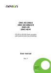
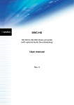
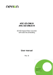
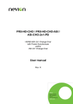
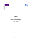
Portable Generator
Small Generator
INDUSTRIAL & DOMESTIC
SMALL GENERATOR
USER’S
USER S GUIDE
Translated from the Korean User’s Manual – February 2014
1
Portable Generator
Small Generator
February 2014
TABLE OF CONTENTS
1.
2.
ACKNOWLEDGMENT
IMPORTANT INFO
3.
4.
5.
6.
7.
8.
9.
10.
INSTALLATION SITE
GENERATOR’S GENERAL CHARACTERISTICS
GENERATOR’S ELECTRICAL CHARACTERISTICS
DIMENSIONS & WEIGHT
NOMENCLATURE
DESCRIPTION & USE OF GENERATOR PARTS
TROUBLESHOOTER
OPERATION SEQUENCE OF GENERATOR
1. ACKNOWLEDGEMENT
The generators were manufactured based on South Korean rigorous standards to
meet international quality and design. Strict quality tests have also been made on
temperature, shock, vibration & noise.
This user manual should always be kept next to the generator.
2. IMPORTANT INFO
The generator rated output is 220V AC or 28V DC voltage and has to be used as
designed. Therefore, depending on the output selected, connect the plug to the
generator in the correct terminal.
Further, the generator is fueled by petrol. Industrial bioethanol (E5 ~ E100) can
also be used (purity: 99%) when available.
2
Portable Generator
Small Generator
3. INSTALLATION SITE
The generator must be used in a well-ventilated and dry place.
When used outdoors, the generator should not be placed under direct
sunlight. It can only be used when effectively protected from it.
It should be placed far from flammable materials or fire, stove or heater.
The floor should be flat.
It should be placed at least 50 cm or more from the wall.
NOTE
The generator’s engine is air-cooled through a cooling system. Therefore,
the cooling fan should always be checked as, in case of failure, the engine
can get damaged.
The engine oil’s level should be checked at all times. It is recommended
to replace it every 250 hours.
You should avoid making work the generator for a long time; avoid
direct sunlight; Use it at ambient temperatures (below 30 ℃) and in
well-ventilated areas.
4. GENERATOR’S GENERAL CHARACTERISTICS
Lightweight, portable generator, convenient and efficient
4 stroke air-cooled petrol engine, long life with easy maintenance
5. GENERATOR’S ELECTRICAL CHARACTERISTICS
Rated output : 1,000 W
[Maximum output : 1,200 W]
Rated voltage : AC 220 V ± 10%
Operating Temperature : -32 ℃ ~ +50 ℃
Noise
: 65 dB (7m distance)
Engine : 4-stroke, air-cooled petrol engine
Cooling : Air-cooled by 220 V fan
Phase : Single
Fuel Tank Capacity : 3.2 Liter
Direct Current : 28 V (battery charging)
3
Portable Generator
Small Generator
Hours of Continuous Operation : 4 Hours
Engine TM-120
1) Number of cylinders : 1
2) Cylinder diameter : 53 mm
3) Cylinder stroke : 42 mm
4) Exhaust amount : 92 cc
5) Lubricated Oil Capacity : 0.35 Liter
6) Lubrication System : Forced Lubrication System
7) Fuel : Bio-Ethanol or petrol (unleaded)
8) Fuel Consumption : 0.7 Liter
6. DIMENSIONS & WEIGHT
Dimensions (mm) : L 368, W 264, H 385
Weight (kg) : 22.0
7. NOMENCLATURE
① Input power cable (Optional)
② Start Switch
③ Output Terminal
④ Power Lamp
⑤ Generator GU-1000K
⑥ Choke Lever
⑦ Starting Rope
⑧ Ground Rod
4
Portable Generator
Small Generator
8. DESCRIPTION & USE OF PARTS
FRONT
Figure 8-1 Front of Generator
LABELS ARE WRITTEN IN KOREAN ON
THE GENERATOR;
TRANSLATION IS IN RED HERE BELOW
No
FUNCTION
Regulators & indicators
1
전원 램프
Power Lamp
Green light is on in operation mode
2
교류과전류차단기
AC Surge Protector
Protects against power surge, circuit overload.
To restore, press on the button.
3
Lights up to indicate low or empty level. It is
엔진오일경고등
Engine oil warning recommended to check level before using the
generator and change oil every 250 hours.
light
4
교류출력단자
AC Output Terminal
Connect the cable.
5
직류과전류차단기
DC Surge Protector
Protects against power surge, circuit overload.
To restore, press on the button.
6
직류출력단자
DC Output Terminal
Connect the generator to charge the battery
7
기동스위치
Start Switch
Up position = ON, fuel is supplied to engine
Down position = STOP, fuel is blocked
5
Portable Generator
Small Generator
BACK
Figure 8-2 Generator Back
No
Regulators &
Indicators
FUNCTION
1
유량조절밸브
Flow Control Valve
Fine adjustment of the flow rate for the control of
combustion efficiency. Use a screwdriver to place it
in the best conditions.
2
쵸크 레버
Choke Lever
To operate and regulate the amount of air
temperature during operation. “START” position,
pull lever up.
3
속도조절기
Speed Control
Adjusting the voltage of the rotational speed of the
engine. To adjust the frequency use the screwdriver
(+) to turn right to increase & left to decrease.
TOP SIDE
Figure 8-3 Top Side of Generator
No
Regulators &
Indicators
FUNCTION
1
유량계
Fuel Level
Fuel Level Indicator L to H
2
연료주입구
Fuel Injection
Open the lid for injecting fuel
6
Portable Generator
Small Generator
LEFT & RIGHT SIDES
Figure 8-4 – Right & Left Side of the Generator
No
Regulators &
Indicators
FUNCTION
1
소음기
Silencer
Exhaust gas is discharged to decrease the noise
generation
2
에어필터
Air Filter
To purify the air entering the engine
3
시동기
Starter
Engine starter
7
Portable Generator
Small Generator
09. TROUBLESHOOTER
PROBLEM
POSSIBLE CAUSE
CORRECTIVE ACTIONS
Generator does 1. Fuel Malfunction
① Check that the start switch is in
not start
ON position
② Check that the choke lever is in
ON position
③ Check that there is enough fuel
2. Bad starter
① Check the engine oil and refill if
low level
① To check if good condition
3. Spark Plug
Starts and then 1. Tank filter is bad
stops does not
continue
to 2. Air filter failure
work
① Check the filter and if bad change
it
① Open the cover, check the air filter
and replace with new one if dirty
3. Bad spark plug
① Replace if does not work
Engine stopped 1. Lack of fuel
suddenly
2. Lack of engine oil
① Check the level and replenish with
fuel.
① Check the gauge, if level low, fill
up to level and restart engine
Engine output 1. Air filter failure
decreases
①Open the cover, check the air filter
and replace with new one if dirty
2. Defective silencer
① Check the silencer, check for
debris or dirt and replace if
necessary
8
Portable Generator
Small Generator
10. OPERATION SEQUENCE OF THE GENERATOR
STARTING SEQUENCE
(1) When all operation switches
are at "stop", "off" position.
(2) Pull the generator choke lever ⑥ up to the "start"
position.
(3) Turn the start switch ② up, from "STOP" position to the "on"
position.
(4) Pull the starting rope ⑦ to start. If this does not help to startup the generator, try again 2-3 times at 5-10 seconds interval after checking
again that the choke lever ⑥ is in ON position.
(5) When the choke lever ⑥ start to "driving" position three minutes left and no
load operation, fuel, oil leaks, excessive vibration and grinding noise, etc.
and check it.
STOP OPERATION
(1) Do not restart the generator for 3 minutes after the start switch ② was
put in the "off" position.
(2) Do not use the generator until it has cooled completely. Place it in a wellventilated place.
9