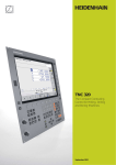
1
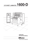
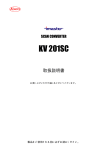
Digital Readouts
for M etrology Applications
May 2010
For many metrology applications, ranging
from simple measuring stations to
complex inspection systems with multiple
measuring points, HEIDENHAIN supports
you with the appropriate digital readouts or
PC solutions.
The functionality always orients itself to the
specifi c application. Whether it is an SPC
inspection station, a tool presetter, a profile
projector, a measuring microscope, or a
manual coordinate measuring machine, the
digital readouts and PC solutions for
metrology applications from HEIDENHAIN
are the right choice for measurement
tasks. There is even a CNC option for the
automation of measurement tasks.
Digital readouts from HEIDENHAIN for
manual machine tools optimally support the
operator with cycles for milling, drilling and
turning. You can fi nd these digital readouts
on the Internet under w w w.heidenhain.de
or in the Position Display Units and Linear
Encoders for Manually Operated Machine
Tools product brochure.
Digital readouts and PC solutions for metrology applications
2
Table of Contents
Overview
Selection Guide
4
ND 1100 QUADRA-CHEK – for simple positioning tasks
6
ND 1200 QUADRA-CHEK – for 2-D geometries
8
Specifications
ND 1300 QUADRA-CHEK – for convenient 2-D measurement
10
ND 1400 QUADRA-CHEK – for manual 3-D measuring machines
12
IK 5000 QUADRA-CHEK – universal PC package solution
14
ND 1200 T TOOL-CHEK – for tool presetters
18
ND 2100 G GAGE-CHEK – for multipoint inspection apparatuses
20
Dimensions
22
Installation, Protective Cover
23
Calibration and Demonstration Parts
24
External Control Elements
25
Optical Edge Detector
26
Servo Amplifi ers
27
Mounting
Accessories
Electrical Connection
Interfaces
Soft ware
Overview
28
Encoder connections
30
Q UADRA-CHEK Wedge
31
Selection Guide
Monitor
Axes
Length
ND 1100 QUADRA-CHEK
• Positioning equipment
• M easuring fi xtures
• Manual coordinate measuring
machines
Monochrome
ND 1200 QUADRA-CHEK
• Profile projectors
• M easuring microscopes
• 2-D measuring machines
Monochrome
Functions
Angle
2 (adjustable)
M easurement series with MIN/M AX display
3 (adjustable)
4 (adjustable)
2 (XY)
–
2 (XY)
1 (Q)
3 (XYZ) –
•
•
•
•
•
M easurement of 2-D features
M easure Magic function
Point measurement with crosshairs
Programming of features and parts
Graphic display of measurement results
•
•
•
•
•
M easurement of 2-D features
M easure Magic function
Point measurement with crosshairs
Programming of features and parts
Graphic display of measurement results
3 (XYZ) 1 (Q)
ND 1300 QUADRA-CHEK
• Profile projectors
• M easuring microscopes
• Video measuring machines
Color
touchscreen
2 (XY)
–
2 (XY)
1 (Q)
3 (XYZ) –
3 (XYZ) 1 (Q)
ND 1400 QUADRA-CHEK
• Manual coordinate measuring
machines
Color
touchscreen
3 (XYZ) 1 (Q)
• M easurement of 2-D and 3-D features
• Points measured via touch probe, crosshairs or rigid
probing element
• M easure Magic function
• Programming of features and parts
• Graphic display of measurement results
• Five coordinate systems can be stored
• Touch-probe management
ND 1200 T TOOL-CHEK
• Tool presetters
Monochrome
2 (XY)
• Point measurement with crosshairs
• 99 tool adapters and 300 tools
ND 2100 G GAGE-CHEK
• Multipoint inspection apparatuses
• SPC inspection stations
Color
4 (adjustable)
ND 200
• M easuring fi xtures
• Adjustment and inspection equipment
• SPC inspection stations
Color
1 (adjustable)
• M etrology and statistical functions (classifi cation,
measurement series, SPC)
IK 5000 QUADRA-CHEK
Universal PC package solution for
• Profile projectors
• M easuring microscopes
• Video measuring machines
• Coordinate measuring machines
PC screen
3 (XYZ) 1 (Q)
• M easurement of 2-D and 3-D features (depending on
the version)
• Point measurement with crosshairs
• Programming of features and parts
• Graphic display of measurement results
• Entry of tolerances
• Import of CAD drawings for direct comparison
–
8 (adjustable)
3 (XYZ) –
3 (XYZ) 1 (Q)
3 (XYZ) 1 (Q)
3 (XYZ) –
3 (XYZ) 1 (Q)
3 (XYZ) 1 (Q)
3 (XYZ) 1 (Q)
4
•
•
•
•
•
•
Programming of up to 100 parts
Graphic display of measurement results
Classifi cation using tolerance and warning limits
M easurement series with MIN/M AX display
Entry of formulas and combinations
Functions for statistical process control (SPC)
Options/Additional functions
Model
Page
Touch probe
ND 1102
6
ND 1103
ND 1104
Optical edge detector
ND 1202
–
ND 1203
8
ND 1100 QUADRA-CHEK
ND 1204
ND 1302
• Optical edge detector
• Video edge detection and live image
ND 1303
display
• Archiving and output of live images
• Zoom and light control, programmable
• CNC axis control and autofocus
ND 1304
10
–
12
ND 1404
ND 1200 QUADRA-CHEK
ND 1300 QUADRA-CHEK
–
ND 1202 T
18
–
ND 2104 G
20
ND 2108 G
Second encoder for sum/difference
display, temperature compensation
ND 287
–
IK 5294
3-D; touch probe
IK 5293
Optical edge detector
IK 5394-EG
3-D; zoom and light control; video
evaluation; touch probe
IK 5394-3D
CNC; optical edge detector
IK 5493
CNC; video evaluation; zoom and light
control; autofocus
IK 5494-2D
Catalog:
Position
Display
Units
ND 2100 G GAGE-CHEK
14
ND 200
IK 5000 QUADRA-CHEK
CNC; 3-D; video evaluation; touch probe; IK 5494-3D
zoom and light control; autofocus
CNC; 3-D; video evaluation; touch probe IK 5594
TP 200; zoom and light control; autofocus
5
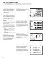
ND 1100 QUADRA-CHEK
– the Digital Readouts for Simple Positioning Tasks
The ND 1100 Q UADRA-CHEK digital
readouts can support up to four axes. They
are mainly suited to positioning tasks on
positioning equipment and measuring
fi xtures, as well as for retrofi tting on
measuring machines for data acquisition
and relaying to a PC.
Display format
Depending on the type of encoder
connected, you can defi ne linear or angular
display individually for each axis.
Description
The ND 1100 Q UADRA-CHEK digital
readouts have a monochrome fl at-panel
screen for displayed values, dialogs, inputs
and soft keys. The robust, diecast
aluminum enclosure meets the demands
of metrology and production control.
Functions
The logical placement of the function keys
and soft keys permits innovative operator
guidance, which supports you when using
the diverse functions.
Along with the usual functions of a digital
readout, such as zeroing and setting of
reference values, the ND 1100 Q UADRACHEK units have numerous more useful
functions:
• Each axis can be confi gured for linear or
angular display
• Minimum/maximum value storage
• Simple switching bet ween counting
directions
• Continuous data output via internal clock,
or upon probing
Data interfaces
You use the data interfaces to output
measurement points as well as to save
settings and compensation values. The
ND 1100 has an RS-232-C/V.24 serial
interface for communication with a PC.
You can connect printers or memory
media directly to the USB port.
Minimum/maximum value storage
The ND 1100 is capable of minimum/
maximum value storage in any freely
selectable axis. The largest and smallest
measured values of a measurement series,
as well as the difference, are stored, and
can be output via the data interface. This
function is especially advantageous during
concentricity testing.
Touch-probe connection
Touch probes (e. g. from HEIDENHAIN or
Renishaw) can be connected to the
ND 1100. The digital readout automatically
reads the current position value during
probing, and also takes the radius of the
stylus into account.
Display format of measured values
Since the universal output formats are
used by various manufacturers of
measuring machines, the ND 1100 can
easily be retrofi tted as a data logger to
manually operated measuring machines.
The measured values are captured by the
ND, and then relayed to a connected PC
for further processing.
6
X
Y
Z
Q
12.3553 mm
-8.2006 mm
20.30.50 dms
326.37.30 dms
ND 1102
ND 1103
ND 1104
Axes
2
3
4
Encoder inputs*
! 1 VPP or " TTL (other interfaces upon request)
Subdivision factor
10-fold (only for 1 VPP)
1)
Display step
Adjustable, max. 7 digits
Linear axis: 1 mm to 0.000 1 mm
Angular axis: 1° to 0.000 1° (00° 00‘ 01“)
Display
5.7” monochrome fl at-panel display for position values, dialogs and inputs, and soft keys
Functions
• M easurement series with MIN/M AX display
• Difference bet ween minimum and maximum (range)
• Scaling factor
Error compensation
• Linear, and segmented over up to 60 points
• Squareness calibration
Data interface
• RS-232-C/V.24
• USB (type A)
Touch-probe connection*
HEIDENHAIN touch probe or Renishaw touch probe
Other connections
Foot switch for t wo functions, or remote keypad
Accessories
Foot switch, remote keypad, protective cover
Main power input
100 V~ to 240 V~ (–15 % to +10 %), 43 Hz to 63 Hz
Operating temperature
0 °C to +45 °C
Protection EN 60 529
IP 00, front panel IP 40
Mounting*
Tilting base or mounting base
Weight
ND with tilting base: approx. 4.8 kg; ND with mounting base: approx. 2 kg
* Please select when ordering
1)
Depends on the signal period of the connected encoder as well as the subdivision factor
7
ND 1200 QUADRA-CHEK
– the Digital Readouts for 2-D Geometries
The ND 1200 digital readouts can support
up to four axes, and function as measuring
computers for 2-D geometries. They are
mainly suited to optical comparators,
measuring microscopes and 2-D measuring
machines.
Description
The ND 1200 Q UADRA-CHEK digital
readouts have a monochrome fl at-panel
screen for displayed values, dialogs and
inputs, graphics functions and soft keys.
The robust, diecast aluminum enclosure
meets the demands of metrology and
production control.
Functions
The appropriate combination of defi ned
function keys and context-dependent soft
keys always provides you with a clear
overview. The innovative operator guidance
provides self-explanatory information about
the various functions. It already supports
you while setting up the coordinate system
(aligning the part and specifying the
datum).
Predefi ned features (point, line, circle) are
available for measurement. The “ M easure
Magic” function makes measurement
especially easy: it selects that feature
which best matches the shape implied by
the points probed. In addition, you can
establish relationships (distances, angles)
bet ween features.
You can apply tolerance values to features
and relationships. Only those tolerances
actually possible are offered for the selected
feature. You can create or automatically
record measuring programs for repeated
parts. The digital readout graphically takes
you to the next measurement position
during program run.
Graphic display
In addition to the position values, the
ND 1200 also displays the features
graphically. Along with the individual
measurement points, the geometrical and
arithmetical deviations are also shown.
Furthermore, for circles the maximum
inscribed circles and minimum
circumscribed circles are shown.
Tolerances
You can apply tolerance values to any
feature. Only those tolerances actually
possible are offered for the selected
feature. This means that a point can only be
assigned a tolerance check for its position,
whereas a circle can be assigned position,
shape and size tolerances.
Defining features
You can use the Q UADRA-CHEK digital
readouts to defi ne features yourself. For
example, this could be a circle whose
position and dimensions are exactly
defi ned, or an alignment line that is at a
specifi ed angle to a measurable line.
The ND 1200 captures measurement points
of plane contours (2-D) either manually via
crosshairs or, as an option, automatically
via the optical edge detector.
Data interfaces
You use the data interfaces to output
measurement points as well as to load and
save settings, compensation values and
programs. The RS-232-C/V.24 serial
interface enables communication with a
PC. You can connect printers or memory
media to the USB port.
8
Measure Magic
The M easure Magic function recognizes
the geometric pattern based on the
distribution of the measurement points,
and automatically calculates which feature
it is, such as a point, line or circle.
If the measurement points are poorly
chosen, then it may not be possible to
determine the feature unambiguously.
M easure Magic then chooses the more
common version. You can have the feature
be displayed graphically, and then select
from the possibilities.
ND 1202
ND 1203
ND 1204
Axes*
2 (XY)
3 (XYQ) or 3 (XYZ)
4 (XYZQ)
Encoder inputs*
! 1 VPP or " TTL (other interfaces upon request)
Subdivision factor
10-fold (only for 1 VPP)
1)
Display step
Adjustable, max. 7 digits
Linear axes XYZ: 1 mm to 0.000 1 mm
Angular axis Q: 1° to 0.000 1° (00° 00‘ 01“)
Display
5.7” monochrome fl at-panel display
for position values, dialogs and inputs, graphics functions and soft keys
Functions
•
•
•
•
•
•
•
Edge detector*
Automatic saving of measurement points via optical edge detector
(option)
Error compensation
• Linear, and segmented over up to 150 points
• Squareness calibration
• Matrix compensation over up to 30 x 30 points
Data interface
• RS-232-C/V.24
• USB (type A)
Other connections
• Foot switch for t wo functions, or remote keypad
• Optical edge detector (only if the option has been chosen)
Accessories
Foot switch, remote keypad, fi ber-optic cables, holder, demo part, protective cover
Main power input
100 V~ to 240 V~ (–15 % to +10 %), 43 Hz to 63 Hz
Operating temperature
0 °C to +45 °C
Protection EN 60 529
IP 00, front panel IP 40
Mounting*
Tilting base or mounting base
Weight
ND with tilting base: approx. 4.8 kg; ND with mounting base: approx. 2 kg
M easurement of t wo-dimensional features (2-D)
Point measurement with crosshairs
Programming of features and parts
M easure Magic: automatic recognition of geometries
Graphic display of measurement results
Entry of tolerances
M easurement series with MIN/M AX display
Upon request
* Please select when ordering
1)
Depends on the signal period of the connected encoder as well as the subdivision factor
9
ND 1300 QUADRA-CHEK
– the Digital Readouts for Convenient 2-D M easurement
The ND 1300 Q UADRA-CHEK digital
readouts can support up to four axes. They
function as measuring computers with 2-D
acquisition of measurement points, suiting
them for measuring microscopes, measuring
projectors and profile projectors, as well as
for video measuring machines if the video
edge detection option is chosen.
Clearly structured display
The large, color, fl at-panel touchscreen
enables simple operation with intuitive
operator guidance, since in each mode only
those functions actually available are
offered for selection. The numeric keypad
and the few basic function keys are located
in ergonomically favorable positions.
Description
The digital readouts of the ND 1300 series
are characterized by the large, color
touchscreen. Their enclosures consist of
robust, diecast aluminum.
Functions
The innovative operator guidance provides
self-explanatory information about the
various functions. It already supports you
while setting up the coordinate system
(aligning the part and specifying the
datum).
Predefi ned features (point, line, circle, slot
and rectangle) are available for measurement.
The “ M easure Magic” function makes
measurement especially easy. In addition,
you can establish relationships (distances,
angles) bet ween features.
You can create or automatically record
measuring programs for repeated parts.
The digital readout graphically takes you to
the next measurement position during
program run.
Depending on the option installed, the
ND 1300 saves measurement points of
plane (2-D) contours either automatically
or manually via crosshairs, optical edge
detection, or a video camera. The integrated
image processing function of the video
option provides a special benefi t: the video
image is shown on the screen in real time,
and can be saved and output via the data
interface. The digital readout even assumes
complete control of the illumination and
the motor zoom.
Data interfaces
You use the data interfaces to output
measurement points as well as to read and
transmit settings, compensation values
and programs. The RS-232-C/V.24 serial
interface enables communication with a
PC. You can connect printers or memory
media to the USB port.
10
Saving of measurement points
The ND 1300 readouts are designed for
2-D measurements. You are provided with
various tools with which you can manually
or automatically save measurement points.
For automatic saving of measurement
points you simply roughly approach the
position. The actual edge is automatically
detected by the active tool (option). This
objective saving of the measurement point
permits a high degree of repeatability. This
makes it possible for you to work quickly
and reliably, without tiring, while at the
same time maintaining a low degree of
measurement uncertainty.
Integrated image processing
The ND 1300 with video option optimally
combines in one unit the functions of a
position display unit with the capability of
displaying the image of the measured
object directly on the screen. The separate
PC with a frame grabber or monitor with
crosshair generator that you would normally
need is not necessary. Video cameras with
S-Video or composite interfaces can be
connected.
Axis positioning
The CNC option lets the ND 1300 work as
a full-fl edged control, directly controlling
the positioning of the X, Y, Z and Q axes.
Servo and stepper motors can be connected.
The necessary servo amplifi ers for t wo or
three axes are available as accessories.
ND 1302
ND 1303
ND 1304
Axes*
2 (XY)
3 (XYQ) or 3 (XYZ)
4 (XYZQ)
Encoder inputs*
! 1 VPP or " TTL (other interfaces upon request)
Subdivision factor
10-fold (only for 1 VPP)
Display step1)
Adjustable, max. 7 digits
Linear axes XYZ: 1 mm to 0.000 1 mm; Angular axis Q: 1° to 0.000 1° (00° 00‘ 01“)
Display
8.4“ color fl at-panel display (touchscreen); resolution: SVGA 800 x 600 pixels, for position values, dialogs
and inputs, graphics functions, soft keys, and display of video images with the Video option
Functions
•
•
•
•
•
•
Edge detector* (option)
• Automatic saving of measurement points via optical edge detector
Video* (option)
•
•
•
•
•
CNC* (option)
• Automation of measurement tasks
• Axis control (for XYZQ) for servo and stepper motors
• Autofocus via step-motor control
Error compensation
• Linear, and segmented over up to 1 000 points
• Squareness calibration; matrix compensation over up to 30 x 30 points
Data interface
RS-232-C/V.24; USB (type A)
Other connections
•
•
•
•
Accessories
Foot switch, remote keypad, fi ber-optic cables, holder, servo amplifi er, calibration standard, demo parts,
protective cover
Main power input
100 V~ to 240 V~ (–15 % to +10 %), 43 Hz to 63 Hz
Operating temperature
0 °C to +45 °C
Protection EN 60 529
IP 00, front panel IP 40
Mounting*
Tilting base or mounting base
Weight
ND with tilting base: approx. 4.8 kg; ND with mounting base: approx. 2 kg
M easurement of t wo-dimensional features (2-D)
Point measurement with crosshairs
Programming of features and parts
M easure Magic: automatic recognition of geometries
Graphic display of measurement results
Entry of tolerances
Automatic saving of measurement points via video edge detection
Manual autofocus (only for Z axis)
Show live images
Archive and output live images ( Archive option, only with the Video and Zoom options)
Zoom and light control, programmable (Zoom option, only with the Video and CNC options)
Foot switch for t wo functions, or remote keypad
Video connection for S-Video and composite (Video option)
Light control over six light sources and zoom control (for Video and Zoom options)
CNC outputs and inputs for joystick (for CNC option)
* Please select when ordering; the Edge detector and Video options cannot be combined
1)
Depends on the signal period of the connected encoder as well as the subdivision factor
11
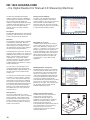
ND 1400 QUADRA-CHEK
– the Digital Readout for Manual 3-D M easuring Machines
The ND 1400 Q UADRA-CHEK digital
readout supports four axes: in addition to
the linear axes XYZ it features an auxiliary
axis Q solely for angular display. The
readout is designed specifi cally for manual
coordinate measuring machines, and can
capture t wo- and three-dimensional
features with its measuring computer
functionality.
Clearly structured display
The large, color, fl at-panel touchscreen
enables simple operation with intuitive
operator guidance, since in each mode only
those functions actually available are
offered for selection. The numeric keypad
and the few basic function keys are located
in ergonomically favorable positions.
Description
The ND 1400 digital readout is characterized
by the large, color touchscreen. Its enclosure
consists of robust, diecast aluminum.
Functions
The innovative operator guidance provides
self-explanatory information about the
various functions. It already supports you
while setting up the coordinate system
(ascertaining the reference plane, aligning
the part and specifying the datum).
Predefi ned features (point, line, circle, slot,
rectangle, plane, cylinder, cone, sphere) are
available for measurement. The “ M easure
Magic” function makes measurement
especially easy: it selects that feature
which best matches the shape implied by
the points probed. In addition, you can
establish relationships (distances, angles)
bet ween all features.
You can create or automatically record
measuring programs for repeated parts.
The digital readout graphically takes you to
the next measurement position during
program run.
You can also use the ND 1400 to measure
3-D features, such as surfaces, cylinders,
cones, etc. The measurement points are
probed with a touch probe. If a triggering
touch probe is used the values are saved
automatically. With rigid probing elements
a key must be pressed. The measured
features can be clearly displayed either in
three dimensions or in one of the three
projection planes.
Data interfaces
You use the data interfaces to output
measurement points as well as to read and
transmit settings, compensation values
and programs. The RS-232-C/V.24 serial
interface enables communication with a
PC. You can connect printers or memory
media to the USB port.
12
Measuring 3-D contours
In addition to the fl at geometric features,
such as points, lines, circles, etc., you can
also use the ND 1400 to measure 3-D
shapes, e. g. cylinders or cones. The screen
displays the feature in three dimensions.
Colored highlighting of each measurement
point lets you identify form errors and any
filtered measured values at a glance. The
ND 1400 also permits 3-D position and
form tolerances, such as fl atness and
parallelism.
Working with the touch probe
The ND 1400 also supports you optimally
while working with touch probes. You can
instantaneously call commercial probing
elements (normal stylus, star stylus), as
well as rigid and tiltable probing heads, all
of which are managed in a library, via the
touchscreen. During probing the ND
automatically takes the direction of probing
into account, as well as the length and
diameter of the stylus. Even complex parts
can be rapidly measured with the fi ve
available coordinate systems.
Saving of measurement points
The ND 1400 saves the measurement
points via the touch probe of the
coordinate measuring machine. A
triggering 3-D touch probe is connected
directly to the digital readout, and the
measured value is transferred
automatically. With a rigid probing element
the measured value must be saved by
pressing a key. You can use the
comprehensive input menu to defi ne
numerous parameters.
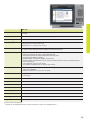
ND 1404
Axes
4 (XYZQ)
Encoder inputs*
! 1 VPP or " TTL (other interfaces upon request)
Subdivision factor*
10-fold (only for 1 VPP)
1)
Display step
Adjustable, max. 7 digits
Linear axes XYZ: 1 mm to 0.000 1 mm
Angular axis Q: 1° to 0.000 1° (00° 00‘ 01“)
Display
8.4“ color fl at-panel display (touchscreen); resolution: SVGA 800 x 600 pixels,
for position values, dialogs and inputs, graphics functions and soft keys
Functions
•
•
•
•
•
•
•
•
•
Error compensation
• Linear, and segmented over up to 1 000 points
• Squareness calibration
• Matrix compensation over up to 30 x 30 points
Data interface
• RS-232-C/V.24
• USB (type A)
Touch-probe connection*
HEIDENHAIN touch probe or Renishaw touch probe
Other connections
Foot switch for t wo functions
Accessories
Mounting base, foot switch, 3-D demo part, protective cover
Main power input
100 V~ to 240 V~ (–15 % to +10 %), 43 Hz to 63 Hz
Operating temperature
0 °C to +45 °C
Protection EN 60 529
IP 00, front panel IP 40
Mounting*
Tilting base or mounting base
Weight
ND with tilting base: approx. 4.8 kg; ND with mounting base: approx. 2 kg
M easurement of t wo-dimensional and three-dimensional features (3-D)
Points measured via crosshairs or rigid probing element
Automatic acquisition of measurement points via touch probe
Programming of features and parts
M easure Magic: automatic recognition of geometries
Graphic display of measurement results, either three-dimensional or in the three projection planes
Entry of tolerances
Five coordinate systems can be stored
Touch-probe management for the various stylus shapes
* Please select when ordering
1)
Depends on the signal period of the connected encoder as well as the subdivision factor
13
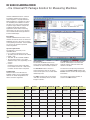
IK 5000 QUADRA-CHEK
– the Universal PC Package Solution for M easuring Machines
IK 5000 Q UADRA-CHEK, the universal
PC package solution for 2-D and 3-D
measuring tasks, is equally suitable for
initial equipping on a machine as well as
for retrofi tting. It is available in versions
for three or four axes, and the optional
expansion stages make it ready for all
coordinate measuring technology
applications and for video measuring
microscopes. You can use it to measure
t wo- and three-dimensional geometries
and their relationships.
Description
IK 5000 Q UADRA-CHEK consists of the
IK 5000 slot card for the PC as well as the
additional necessary slot covers, and the
corresponding PC soft ware. Once installed
on your PC you will have a powerful
measuring station.
System requirements
The following is necessary to run
Q UADRA-CHEK:
• PC: # dual-core Pentium, 2.66 GHz
• Operating system: Windows XP or Vista
• RA M: # 1GB
• Hard disk: At least 500 M B available
• One PCI slot and one, t wo or three
additional empty slots (depending on the
version)
• Screen:
Resolution at least 1024 x 768 pixels;
for the video function: 22“ widescreen,
resolution at least 1680 x 1050 pixels
Configuration
Various versions of the IK 5000 are
available. Please see the confi guration
table for the model designations and
various functions supported.
User interface
The IK 5000 Q UADRA-CHEK screen
shows various confi gurable windows and
tool fi elds for clear and simple operation.
The Template windows list all measured
features, relationships and constructed
features together with their values and
tolerances in tables.
The Part View window shows the
measured features with the accepted
measurement points. You can also defi ne
relationships here.
The element currently being measured is
shown in the Feature Stamp window. The
Results window contains all corresponding
information.
The Video window (only in the version
with video evaluation) shows the video
image in real time.
The current measurement position is
shown in the DRO window.
IK 5294
IK 5293
IK 5394-EG IK 5394-3D IK 5493
IK 5494-2D IK 5494-3D IK 5594
Axes
4 XYZQ
3 XYZ
4 XYZQ
4 XYZQ
3 XYQ
4 XYZQ
4 XYZQ
4 XYZQ
2-D geometries
!
!
!
!
!
!
!
!
3-D geometries
–
!
–
!
–
–
!
!
Optical edge detector
–
–
!
–
!
–
–
–
Video evaluation
–
–
–
!
–
!
!
!
Zoom and light control
–
–
–
!
–
!
!
!
Autofocus
–
–
–
–
–
!
!
!
Touch probe
–
!
–
!
–
–
!
TP200
CNC function
–
–
–
–
!
!
!
!
14
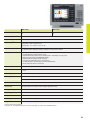
IK 5000
Axes1)
3 (XYQ), 3 (XYZ) or 4 (XYZQ)
Encoder inputs*
! 1 VPP or " TTL (other interfaces upon request)
Subdivision factor
Up to 100-fold, selectable via dip switch; default setting: 50-fold (only for 1 VPP)
2)
Display step
Adjustable, max. 7 digits
Linear axes XYZ: 1 mm to 0.000 1 mm
Angular axis Q: 1° to 0.000 1° (00° 00‘ 01“)
Display
Via PC screen
Functions
•
•
•
•
•
•
•
Edge detector1)
• Automatic saving of measurement points via optical edge detector
Video1)
•
•
•
•
•
•
•
Automatic saving of measurement points via video edge detection
Manual autofocus
Show live images
Archiving and output of live images
Zoom and light control, programmable (with the Light/Zoom versions)
Video connection for digital USB camera (with the Video versions)
Light control over six light sources and zoom control (with the Video and Light/Zoom versions)
CNC 1)
•
•
•
•
Automation of measurement tasks
Axis control (for XYZQ) for servo and stepper motors
Autofocus via stepper-motor control (Z axis)
CNC outputs and inputs for joystick
Error compensation
• Linear, and segmented over any number of points
• Squareness calibration
• Matrix compensation over up to 50 x 50 points
Other connections
• Foot switch for t wo functions
Accessories
Foot switch, fi ber-optic cables, holder for fi ber-optic cables, servo amplifi er, calibration standard,
demo part, distribution cable
PC interface
PCI
Dimensions
100 mm x 250 mm
M easurement of t wo-dimensional features (2-D)
M easurement of three-dimensional features (3-D)1)
Point measurement with crosshairs
Programming of features and parts
M easure Magic: automatic recognition of geometries
Graphic display of measurement results
Entry of tolerances
* Please select when ordering
1)
See the confi guration table for possible combinations
2)
Depends on the signal period of the connected encoder as well as the subdivision factor
15
IK 5000 QUADRA-CHEK
– Functions
The innovative operator guidance provides
self-explanatory information about the
various functions. It already supports you
while setting up the coordinate system
(aligning the part and specifying the datum).
Various predefined features are available for
measurement, depending on the version:
2-D saving: Point, line, circle, slot, rectangle
3-D saving: Plane, cylinder, cone, sphere
The “ M easure Magic” function makes
measurement especially easy: it selects
that feature which best matches the shape
implied by the points probed.
With IK 5000 Q UADRA-CHEK you can
defi ne features yourself (for example, a
circle whose position and dimensions are
exactly specifi ed). In addition, you can
establish relationships (distances, angles)
bet ween features.
M easuring programs that you create
yourself or record automatically simplify
the efforts necessary for repeated parts.
The digital readout graphically takes you to
the next measurement position during
program run.
Depending on the version, IK 5000
Q UADRA-CHEK saves measurement
points of plane (2-D) contours either
automatically or manually via crosshairs,
via optical edge detection, or via a video
camera.
For 3-D contours, such as planes, cylinders,
cones and spheres, the measurement
points are saved by probing with a touch
probe. If a triggering touch probe is used
the values are saved automatically. With
rigid probing elements a key must be
pressed.
Multi-sensor scanning
Along with the usual method for saving
measurement points, the IK 5494 and
IK 5594 versions permit multi-sensor
scanning: in addition to the video camera,
the measuring machine is also equipped
with a touch probe. You can then use the
touch probe to measure 3-D features on
the object, and enjoy the advantages of
video evaluation for 2-D features. The
integrated probe library manages the
various measurement tools for you,
whether they be optical, video, laser or
touch-probe systems.
Constructed features
Q UADRA-CHEK gives you several
possibilities for determining dimensions:
• M easuring the features
• Calculating the features (e. g. the center
point of a measured circle)
• Establishing a relationship bet ween
features (e. g. distance bet ween t wo
circle center points, angle bet ween t wo
lines)
However, you can also construct new
features from existing features and from
relationships. The properties of these
constructed features can then be seen
directly in the parts view.
Data management
The integrated data-report generator for
customized forms, databases and tolerance
checks is used to archive, export and
import data in numerous formats. Use the
integrated spreadsheets for complex and
non-standard calculations.
Simply send your customized reports to a
printer, or make the data available to other
users in a database.
The measured features can be clearly
displayed either in three dimensions or in
one of the three projection planes.
Functional ViewActive window
Q UADRA-CHEK provides you with a
comprehensive, graphical View Active
window. You can choose bet ween a 3-D
view, or a projection in the XY, YZ or ZX
planes. Additionally, you can magnify,
reduce, zoom, shift or rotate the views.
You can defi ne tolerances and constructed
features in any view. The "pass/fail" color
coding makes it easy to determine whether
the part matches the specifi cations.
16
Programming of parts
Diffi cult and repetitive measuring tasks can
be simplifi ed with the aid of a program that
you either create yourself or record automatically during measurement of the first
part. Q UADRA-CHEK learns the reference
points, the sequence of measurements,
tolerances and data-output commands.
Q UADRA-CHEK visually leads you to the
features to be probed when the program is
run. The program view also provides you
with an optimum overview of the process.
Integrated image processing
The integrated image processing function
included with the video-function versions
provides a special benefi t: the video image
is shown on the screen in real time and
can be saved. Q UADRA-CHEK can even
assume complete control of the illumination
and the motor zoom. A digital USB camera
can be connected.
In order to quickly and directly compare the
actual status and nominal status, import
the parts drawing in DXF or IGS format,
and place it over the video image.
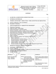
Excerpt from the possibilities for the
construction of features:
2-D possibilities
Y
X
Intersection of t wo lines
X
Intersection of line and
circle
X
Intersection of t wo
circles
X
Hole circle formed from
three or more circles
Y
Y
Y
Y
Bisector of t wo lines
X
Axis positioning
The CNC versions of IK 5000 Q UADRACHEK work as full-fl edged controls, directly
controlling the positioning of the X, Y, Z and
Q axes. Servo and stepper motors can be
connected. The necessary servo amplifi ers
for t wo or three axes are available as
accessories.
Automating
Programs running in combination with the
CNC function of IK 5000 Q UADRA-CHEK
run automatically. This minimizes the effects
of subjective assessments, and increases
data throughput noticeably. By automating
series of measurements and complex
procedures, you spare yourself the strain
of performing repetitive measuring tasks.
3-D possibilities
Y
Z
Intersection of cylinder
and surface
X
Y
Z
3-D line
X
Plane from plane and
3-D line
X
Cone taper
X
Intersection of sphere
and line
Y
Z
Y
Z
17
ND 1200 T TOOL-CHEK
– the Digital Readout for Tool Presetters
The TO OL-CHEK ND 1200T digital readout
is designed specifi cally for tool presetters.
It supports X and Z axes.
Description
The ND 1200T has a monochrome flat-panel
display. The robust, diecast aluminum
enclosure meets the demands of production
fl oors.
Functions
The self-explanatory user guidance of the
TO OL-CHEK ND 1200T digital readout
provides you with optimum support for all
functions.
You can defi ne up to 99 tool adapters for
the tool holder. You can select either an
absolute reference point, or one that refers
to a master adapter. You can defi ne the axis
association and counting direction separately
for each adapter.
Tool measurement usually consists of
measuring the length and diameter or
radius of a tool. You can also measure radii
(e. g. for spherical cutters) and angles
(e. g. for indexable inserts or lathe tools).
The ND 1200T stores up to 300 tools.
You can respectively show and print each
actual value, nominal value and deviation.
Measuring radii and angles
You probe several points with the crosshairs
in order to measure the radius. The digital
readout calculates the radius and any form
error from this. In order to measure a
cutting edge angle, probe the t wo sides of
the angle at t wo points each. The results
are the intersection of the t wo lines as well
as the inside angle “A”.
Label printing
You can connect various label printers via
the USB port. The control commands
necessary for this are already set, and can
be called via the menu function.
You can group various tools, e. g. those that
are necessary for machining a certain part.
Create this setup plan either by selecting
the tools from the tool list, or by measuring
each tool.
For tools that are too large to be shown on
the projector, such as teeth with a radius,
you can freeze an axis for measurement.
If a tool has more than one tooth, then you
use the incremental function to ascertain
the tool data in reference to the master
tooth as well.
Data interfaces
You use the data interfaces to transmit the
tool data and to load and save settings,
compensation values and saved tools. The
RS-232-C/V.24 serial interface enables
communication with a PC. You can connect
printers or memory media to the USB port.
18
Tool list
You can also store the data of all measured
and numbered tools, and even print this
data in a clearly structured list. Use the menu
to specify which information is included in
the list.
ND 1202 T
Axes
2 (XZ)
Encoder inputs*
! 1 VPP or " TTL (other interfaces upon request)
Subdivision factor*
10-fold (only for 1 VPP)
1)
Display step
Adjustable, max. 7 digits
Linear axis: 1 mm to 0.000 1 mm
Angular axis: 1° to 0.000 1° (00° 00‘ 01“)
Display
5.7” monochrome fl at-panel display
for position values, dialogs and inputs, and soft keys
Functions
•
•
•
•
•
•
•
Error compensation
• Linear, and segmented over up to 150 points
• Parallelism error
Data interface
• RS-232-C/V.24
• USB
Other connections
Foot switch for t wo functions, or remote keypad
Accessories
Foot switch, remote keypad, protective cover
Main power input
100 V~ to 240 V~ (–15 % to +10 %), 43 Hz to 63 Hz
Operating temperature
0 °C to +45 °C
Protection EN 60 529
IP 00, front panel IP 40
Mounting*
Tilting base or mounting base
Weight
ND with tilting base: approx. 4.8 kg; ND with mounting base: approx. 2 kg
Point measurement with crosshairs
99 tool adapters
M emory for 300 tools
Counting direction and axis assignment depend on the adapter
Radius/diameter switching
Entry of tolerances
Circle and angle measurement
* Please select when ordering
1)
Depends on the signal period of the connected encoder as well as the subdivision factor
19
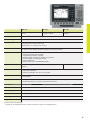
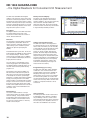
ND 2100 G GAGE-CHEK
– the Digital Readouts for Multipoint Inspection Apparatuses
The ND 2100 G GAGE-CHEK readouts are
versatile metrology displays for measuring
and inspection tasks in manufacturing and
quality assurance. With inputs for up to
eight encoders, they are predestined for
multipoint measurements from simple
pass/fail detection up to complex SPC
evaluation.
Position display
The display values appear in large, easy-toread numbers. Values outside the tolerance
are color-coded, immediately notifying you
of errors.
Description
The ND 2100 G readouts have a robust,
diecast aluminum enclosure, and a
keyboard suited to their environment.
A large, graphic, color screen displays the
measured values, the soft-key row and
other information.
Functions
The inputs can be assigned and combined
as desired with mathematical, trigonometric
or statistical formulas. This makes it possible
to measure even complex dimensions
such as thickness, fl atness, volume and
more. The results are displayed numerically
or graphically as a color bar graph or a dial,
or archived for statistical process control
(SPC). The GAGE-CHEK can be confi gured
for basic or advanced applications. Soft
keys and function keys can be adapted as
required. The Min/Max function of the
ND 2100 G readouts monitors and stores
the highest and lowest measured or
calculated value. Warning and tolerance
limits can be assigned to each display
value. Results outside of the tolerance are
marked with a different color. An acoustic
alarm sounds simultaneously. Tolerance
values, SPC parameters and custom
formulas are stored for individual parts.
GAGE-CHEK can manage up to 100 parts,
each with up to 16 visible measurement
features and 16 hidden measurement
features. The rapid acquisition of measurement data makes monitoring dynamic
events, such as the eccentricity of a rotating
shaft, possible.
Data interfaces
The GAGE-CHEK features various
interfaces for communicating with parent
systems:
• RS-232-C/V.24 for PC, also for remote
operation of the GAGE-CHEK
• USB
20
Bar diagram
You can select to have the values shown
as a color-enhanced vertical or horizontal
bar graph. The defi ned warning limits and
tolerance limits provide instant feedback.
If these limits are exceeded, the column
color changes from green to yellow or red,
informing you explicitly of critical
dimensions.
SPC and data storage
GAGE-CHEK includes integrated SPC
studies such as mean value charts (X bar)
and range charts (R). Min, max, sigma, cp
and cpk are also calculated, and are clearly
displayed as a graph or histogram. Historical
raw data can be saved in a tabular numeric
display. Each dimension and all data are
time and date stamped.
Formulas and combinations
You can use mathematical and trigonometric
formulas, as well as logical conditions, to
combine individual measured values or
measurement sequences with each other,
and so create complex calculations. This
can be used, for example, to calculate and
display the circumference of a turned part,
the volume of a cube, or the angle bet ween
t wo cams, and also to assign tolerance
limits to these values.
ND 2104 G
ND 2108 G
Axes
4
8
Encoder inputs*
! 1 VPP or " TTL (other interfaces upon request)
Subdivision factor
10-fold (only for 1 VPP)
1)
Display step
Adjustable, max. 7 digits
Linear axis: 1 mm to 0.000 01 mm
Angular axis: 1° to 0.000 1° or 00° 00‘ 01“
Display
5.7” color fl at-panel display
for position values, dialogs and inputs, graphics functions and soft keys
Functions
•
•
•
•
•
•
•
•
Error compensation
• Linear, and segmented over up to 200 points
Data interface
• RS-232-C/V.24
• USB
Switching inputs
5 TTL inputs (freely defi nable)
Switching outputs
12 TTL outputs (freely defi nable)
Part-programming of up to 100 parts
Graphic display of measurement results
Classifi cation using tolerance and warning limits, with display as a bar graph
M easurement series with MIN/M AX display
Mathematical and trigonometric formulas
Functions for statistical process control (SPC)
Graphic display of measurement results and distribution
Data storage of values and formulas
2 relay outputs
Other connections
Foot switch for t wo functions
Accessories
Mounting base, foot switch, remote keypad, protective cover
Main power input
100 V~ to 240 V~ (–15 % to +10 %), 43 Hz to 63 Hz
Operating temperature
0 °C to +45 °C
Protection EN 60 529
IP 40
Mounting*
Tilting base or mounting base
Weight
ND with tilting base: approx. 4.8 kg; ND with mounting base: approx. 2 kg
* Please select when ordering
1)
Depends on the signal period of the connected encoder as well as the subdivision factor
21
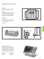
Mounting
Dimensions of ND 1000/ND 2000
ND 1300 with tilting base
#$%&
(#&
!(+
!*)
()
'%$&
!'"
!
Dimensions in mm
,-./012342567896*"(&
7896!)'*6:6;6<
=6'6;;>6?"%!6;;
22
!""
!!"%&
Mounting and Protection
Mounting
The ND 1000 and ND 2000 are shipped
with either a tilting base or a mounting
base.
!"$%!
@&
!""
(&*%)&
Tilting base
The readout can be used as a tabletop unit
when placed on the tilting base. The readout
can then be tilted for ward or backward by
up to 20° for the best reading angle. The
tilting base can be attached with M5 screws.
ID 382 892-02
!'"
Mounting base
The mounting base is used to attach the
ND 1000 or ND 2000 to a mounting arm or
directly on the machine. It also permits
tilting of the readout.
ID 682 419-01
"
+$%&
(!&
$*
!"$%&
@'%$6:6(%$6D6('%&
A(B+6:6!"C6D6"%'&CE
!)%&
&&
"
Mounting base
Protective cover (accessory)
Protective covers are accessories for
protecting the keyboard and screen of the
ND 1000/ND 2000 from becoming soiled.
The display can still be easily read through
the transparent protective covers. They fi t
themselves optimally to the front of the unit,
without impairing the ease of operation.
ND
ND
ND
ND
11xx; 1/2 axes
11xx; 3/4 axes
12xx
21xx
ID
ID
ID
ID
681 051-02
681 051-03
681 051-01
681 051-04
23
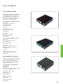
Accessories
Calibration and Demonstration Parts
HEIDENHAIN offers various calibration
parts as accessories in order to calibrate
the optical and tactile edge detection
methods.
Calibration standard
For the calibration of video measuring
machines, measuring microscopes and
profile projectors. It can be traced back to
the national or international standards.
ID 681 047-01
2-D demo part
The 2-D demo part is included with the
ND 1200, ND 1300 and IK 5000. The
application examples in the User’s Manuals
are based on this part. It can be reordered
if a replacement is necessary.
ID 681 047-02
3-D demo part (accessory)
Demo part for touch-probe applications.
Examples in the ND 1400 and IK 5000
User’s Manuals are based on this part.
ID 681 048-01
3-D demo part for multi-sensor
scanning (accessory)
Demo part specifi cally for applications that
combine touch-probe systems and video
edge detection. It is used for the examples
in the IK 5000 User’s Manual.
ID 681 048-02
24
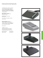
External Control Elements
The digital readouts and the PC package
can be operated easily and intuitively.
However, remote operability may also be
useful and convenient in some situations.
The following components are available for
remote operation:
Foot switch (accessory)
With t wo freely assignable keys
Cable length: 2.4 m
For ND with RJ 45 connector
ID 681 041-01
For IK 5000 with 3-pin DIN connector
ID 681 041-02
Remote keypad (accessory)
For remote operation of the digital
readouts; features a numeric keypad and
“enter” and “fi nish” keys; cable length:
4.5 m; with RJ 45 connector.
ID 681 043-01
Joystick (accessory)
For remote operation and sensitive
traversing of axes for ND 1300 and
IK 5000. With 15-pin D-sub connector.
Without trackball
With trackball
ID 681 044-02
ID 681 044-01
25
Accessories
Optical Edge Detector
Two fi ber-optic cables are necessary for
edge detection with the optical edge
detector. One fi ber-optic cable is attached
to the projection screen with a transparent
holder. The second cable is attached near
the transmitted light source so that the
fi bers point toward the light source. The
following accessory components are
required.
Fiber-optic cable (accessory)
With one right-angle end and an SM A
connector (subminiature A) for ND or IK.
Bend radius: # 25 mm
Temperature: $ 100 °C
Lengths: 2 m, 3 m, 5 m
ID 681 049-xx
Holder (accessory)
With a hole for accepting the right-angle
end of fi ber-optic cables. Transparent
design so that it can be attached to the
projection screen.
Lengths: 350 mm, 600 mm, 760 mm
ID 681 050-xx
Fiber-optic cable connector (accessory)
Two SM A connectors (subminiature A) for
connecting an integrated edge detector.
Bend radius: # 25 mm
Temperature: $ 100 °C
Lengths: 2 m, 3 m, 5 m
ID 681 049-xx
26
Servo Amplifi ers
Servo amplifiers for CNC
For the versions with CNC axis positioning,
HEIDENHAIN supplies the appropriate
servo amplifi ers both for stepper motors
and for servo motors. The cables for
connection to the digital readout or the PC
are included in the items supplied.
Servo amplifier for CNC stepper motor
(accessory)
For t wo-phase stepper motors
Line voltage: 240 V
Rated voltage: 48 V–
For 2 axes:
Current per axis: $ 2.5 A
Power per axis: $ 120 W
ID 681 045-01
For 3 axes:
Current per axis: $ 1.67 A
Power per axis: $ 80 W
ID 681 045-02
Servo amplifier for CNC servo motor
(accessory)
For servo motors with brushes
Line voltage: 240 V
Rated voltage: 48 V–
For 2 axes:
Continuous current per axis: $ 3 A
Rated power per axis: $ 150 W
ID 681 046-01
For 3 axes:
Continuous current per axis: $ 2 A
Rated power per axis: $ 100 W
ID 681 046-02
Servo amplifier for zooming
A separate servo amplifi er is necessary for
the zoom function of the ND 1300. It can
also be used for the IK 5000 if the
performance of the integrated amplifi er
does not suffi ce (0.4 W).
Servo amplifier for zooming with
stepper motor
(accessory)
For t wo-phase stepper motors in open-loop
systems (e.g. for Navitar zoom)
Line voltage: 100 V to 240 V
Rated voltage: 12 V–
Current: $ 2 A
Power: $ 160 W
With EU power cable
ID 722 334-02
With US power cable
ID 722 334-01
27
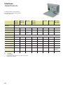
Interfaces
Digital Readouts
The digital readouts feature interfaces
for encoders, for communication and for
external components.
ND 1102
ND 1103
ND 1104
ND 1202
ND 1203
ND 1204
ND 1302
ND 1303
ND 1304
ND 1404
ND 1202 T
ND 2104 G
ND 2108 G
Encoders
1 VPP or TTL
Touch probe
!1)
–
–
–
–
!1)
–
–
Video
–
–
–
!2)
–
–
–
–
Option
Upon
request
–
!
–
–
–
Fiber-optic cable
–
Optical edge detector
Data
RS-232-C/V.24 and USB type A
Light control
–
–
–
Option
–
–
–
–
Zoom
–
–
–
Option
–
–
–
–
CNC outputs
–
–
–
Option
Option
–
–
–
Foot switch
!
!
!
!
!
!
!
!
Remote keypad
!
!
!
!
!
–
!
!
Switching outputs
–
–
–
–
–
–
–
12 TTL
2 relays
Switching inputs
–
–
–
–
–
–
–
5 TTL
!
–
1)
2)
28
= Standard
= Not available
HEIDENHAIN touch probe or Renishaw touch probe
S-Video and composite
IK 5000
Connections to the IK 5000 are made via
its D-sub connectors. Depending on the
version, further connections are made
through one, t wo or three additional slot
covers. Please order the adapter cables
necessary bet ween the individual
components separately.
Slots1)
IK 5293
IK 5294
IK 5394-EG IK 5394-3D IK 5493
IK 5494-2D IK 5494-3D IK 5594
2
2
3
4
3
4
4
4
Location
Encoders for
X, Y, Z
IK
1 VPP or TTL
CNC outputs
IK
–
–
–
–
!
!
!
!
Foot switch
IK
!
!
!
!
!
!
!
!
Fiber-optic cable
Slot L
–
–
!2)
–
!2)
–
–
–
Touch probe3)
Slot 1
!
–
–
!
–
–
!
TP 200
Light control
Slot 1
–
–
–
!
–
!
!
!
Encoder for Q
Slot 2
–
1 VPP or TTL
Zoom
Slot 3
–
–
–
!
–
!
!
!
Video
PC
–
–
–
USB
4)
camera
–
USB
camera4)
USB
camera4)
USB
camera4)
! = Standard; – = Not available
1)
Including IK; 2) Connected directly to the IK PCB, special slot cover with cable guide included in delivery
3)
HEIDENHAIN touch probe or Renishaw touch probe; 4) Connected to the USB port of the PC
Adapter cables
Complete with D-sub connector (female),
15-pin (1 VPP) or 9-pin (TTL), and 3-pin
mini-DIN connector (female)
1 VPP
TTL
For 3 axes XYZ and foot switch
540 550-40
540 550-10
For 2 axes XY and foot switch
540 540-24
540 540-05
540 541-24
540 541-05
(6;
For connecting the XYZ encoders and
the foot switch to the IK 5000
"%(&66;
Complete with D-sub connector (female),
15-pin (1 VPP) or 9-pin (TTL)
(6;
For connecting the Q encoder to the
IK 5000
29
Interfaces
Encoders
Depending on the versions, the digital
readouts and the PC board are designed
for encoders with 1 VPP or TTL interface.
Other interfaces are available upon request.
A distribution cable is necessary in order to
attach the encoders to the IK 5000.
Pin layout ! 1 VPP
Mating connector:
15-pin D-sub connector (male)
Power supply
! 1 VPP
Incremental signals
Others
4
12
2
10
1
9
3
11
14
7
5/6/8/
13/15
UP
Sensor
UP
0V
Sensor
0V
A+
A–
B+
B–
R+
R–
/
Cable shield connected to housing; UP = power supply voltage
Sensor: The sensor line is connected in the encoder with the corresponding power line.
Vacant pins or wires must not be used!
Pin layout " TTL
Mating connector:
9-pin D-sub connector (male)
Power supply
"#TTL
Incremental signals
7
6
1
2
3
4
5
9
8
UP
0V
/
Ua1
$
Ua2
%
Ua0
&
Cable shield connected to housing; UP = power supply voltage
Vacant pins or wires must not be used!
30
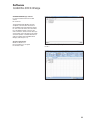
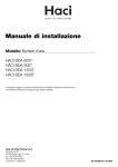
Software
Q UADRA-CHEK Wedge
QUADRA-CHEK Wedge software
For communication bet ween the ND
and PC
ID 709 141-01
The Q UADRA-CHEK Wedge soft ware
simplifi es communication bet ween an
ND 1000/ND 2000 and a Windows-based
PC. The measured values are transmitted
from the digital readout to the PC via a
V.24 connection, and are written directly to
an Excel table, where the data can be edited,
saved and printed. A suitable V.24/RS-232
cable is included with Q UADRA-CHEK
Wedge (cable length: 3 m).
System requirements
Windows XP, Vista or 7
Internet Explorer 6.0 or higher
Excel 2003 or later
The values measured by the digital readout are transmitted to
the PC ...
...and can be saved in an Excel table.
31
!"#$%&'())*+$'*,!*)'(,)$-./'
!"#$%&'())*+$,*-.*)'(-)$/0"(1*23
01123$45678597:;$-95.68<
! 4562788629:$;
" 4562788623;8:
<$=(->?2-)@&A'*-.*)'(-)#.*
DE
HEIDENHAIN Technisches Büro Nord
12681 Berlin, Deutschland
" 030 54705-240
ES
FARRESA ELECTRONICA S.A.
08028 Barcelona, Spain
w w w.farresa.es
PH
Machinebanks` Corporation
Quezon City, Philippines 1113
E-mail: [email protected]
HEIDENHAIN Technisches Büro Mitte
08468 Heinsdorfergrund, Deutschland
" 03765 69544
FI
HEIDENHAIN Scandinavia AB
02770 Espoo, Finland
w w w.heidenhain.fi
PL
APS
02-489 Warszawa, Poland
w w w.apser wis.com.pl
HEIDENHAIN Technisches Büro West
44379 Dortmund, Deutschland
" 0231 618083-0
FR
HEIDENHAIN FRANCE sarl
92310 Sèvres, France
w w w.heidenhain.fr
PT
FARRESA ELECTRÓNICA, LDA.
4470 - 177 Maia, Portugal
w w w.farresa.pt
HEIDENHAIN Technisches Büro Südwest
70771 Leinfelden-Echterdingen, Deutschland
" 0711 993395-0
GB
HEIDENHAIN (G.B.) Limited
Burgess Hill RH15 9RD, United Kingdom
w w w.heidenhain.co.uk
RO
HEIDENHAIN Reprezentanţă Romania
Braşov, 500338, Romania
w w w.heidenhain.ro
HEIDENHAIN Technisches Büro Südost
83301 Traunreut, Deutschland
" 08669 31-1345
GR
MB Milionis Vassilis
17341 Athens, Greece
w w w.heidenhain.gr
RS
Serbia ! BG
RU
OOO HEIDENHAIN
125315 Moscow, Russia
w w w.heidenhain.ru
SE
HEIDENHAIN Scandinavia AB
12739 Skärholmen, Sweden
w w w.heidenhain.se
HK
AR
NAKASE SRL.
B1653AOX Villa Ballester, Argentina
w w w.heidenhain.com.ar
HEIDENHAIN LTD
Kowloon, Hong Kong
E-mail: [email protected]
HR
Croatia ! SL
AT
HEIDENHAIN Techn. Büro Österreich
83301 Traunreut, Germany
w w w.heidenhain.de
HU
HEIDENHAIN Kereskedelmi Képviselet
1239 Budapest, Hungary
w w w.heidenhain.hu
SG
HEIDENHAIN PACIFIC PTE LTD.
Singapore 408593
w w w.heidenhain.com.sg
AU
FCR Motion Technology Pty. Ltd
Laverton North 3026, Australia
E-mail: [email protected]
ID
PT Servitama Era Toolsindo
Jakarta 13930, Indonesia
E-mail: [email protected]
SK
KOPRETINA TN s.r.o.
91101 Trencin, Slovakia
w w w.kopretina.sk
BA
Bosnia and Herzegovina ! SL
IL
SL
BE
HEIDENHAIN NV/SA
1760 Roosdaal, Belgium
w w w.heidenhain.be
NEUMO VARGUS MARKETING LTD.
Tel Aviv 61570, Israel
E-mail: [email protected]
Posredništvo HEIDENHAIN
NAVO d.o.o.
2000 Maribor, Slovenia
w w w.heidenhain-hubl.si
IN
HEIDENHAIN Optics & Electronics
India Private Limited
Chennai – 600 031, India
w w w.heidenhain.in
TH
HEIDENHAIN (THAILAND) LTD
Bangkok 10250, Thailand
w w w.heidenhain.co.th
BG
ESD Bulgaria Ltd.
Sofi a 1172, Bulgaria
w w w.esd.bg
BR
DIADUR Indústria e Comércio Ltda.
04763-070 – São Paulo – SP, Brazil
w w w.heidenhain.com.br
BY
Belarus
GERTNER Service GmbH
50354 Huerth, Germany
w w w.gertner.biz
HEIDENHAIN CORPORATION
Mississauga, OntarioL5T2N2, Canada
w w w.heidenhain.com
CA
CH
CN
CZ
DK
·
T&M Mühendislik San. ve Tic. LTD. ŞTI.
34728 Ümraniye-Istanbul, Turkey
w w w.heidenhain.com.tr
IT
HEIDENHAIN ITALIANA S.r.l.
20128 Milano, Italy
w w w.heidenhain.it
TR
JP
HEIDENHAIN K.K.
Tokyo 194-0215, Japan
w w w.heidenhain.co.jp
TW
HEIDENHAIN Co., Ltd.
Taichung 40768, Taiwan R.O.C.
w w w.heidenhain.com.t w
KR
HEIDENHAIN Korea LTD.
Gasan-Dong, Seoul, Korea 153-782
w w w.heidenhain.co.kr
UA
Gertner Service GmbH Büro Kiev
01133 Kiev, Ukraine
w w w.gertner.biz
ME
Montenegro ! SL
US
MK
Macedonia ! BG
HEIDENHAIN CORPORATION
Schaumburg, IL 60173-5337, USA
w w w.heidenhain.com
MX
HEIDENHAIN CORPORATION MEXICO
20235 Aguascalientes, Ags., M exico
E-mail: [email protected]
VE
Maquinaria Diekmann S.A.
Caracas, 1040-A, Venezuela
E-mail: [email protected]
MY
ISOSERVE Sdn. Bhd
56100 Kuala Lumpur, Malaysia
E-mail: [email protected]
VN
HEIDENHAIN s.r.o.
102 00 Praha 10, Czech Republic
w w w.heidenhain.cz
AMS Advanced Manufacturing
Solutions Pte Ltd
HC M City, Viêt Nam
E-mail: [email protected]
NL
HEIDENHAIN NEDERLAND B.V.
6716 B M Ede, Netherlands
w w w.heidenhain.nl
ZA
TP TEKNIK A/S
2670 Greve, Denmark
w w w.tp-gruppen.dk
MAFEMA SALES SERVICES C.C.
Midrand 1685, South Africa
w w w.heidenhain.co.za
NO
HEIDENHAIN (SCHWEIZ) AG
8603 Schwerzenbach, Switzerland
w w w.heidenhain.ch
DR. JOHANNES HEIDENHAIN
(CHINA) Co., Ltd.
Beijing 101312, China
w w w.heidenhain.com.cn
683 330-22 · 10 · 5/2010 · F& W · Printed in G ermany
HEIDENHAIN Scandinavia AB
7300 Orkanger, Nor way
w w w.heidenhain.no
!"#$%&'&&()**!
Zum Abheften hier falzen! / Fold here for filing!
Vollständige und weitere Adressen siehe www.heidenhain.de
For complete and further addresses see www.heidenhain.de
===#>9?@98>6?8#@9