1
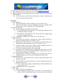
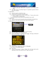
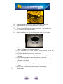
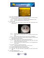
Date Created: May 3, 2004
Date Modified: June 1, 2005
MA6/BA6 Mask Aligner
Equipment Standard Operating Procedure
Greg Allion and Kimberly Appel
1. Purpose
1.1. Photolithography involves transferring a pattern from a mask to a wafer coated
with photo resist.
1.2. MA6 has the capability of processing both top and backside alignment.
1.3. This tool is primarily used for high-resolution lithography (<2µm) and/or critical
alignment tolerances (<1µm).
2. Reference Documents
2.1. Karl Suss MA6 User Manual
3. Equipment
3.1. Tweezers
3.2. N2 gun
3.3. Vacuum wand
4. Materials
4.1. N/A
5. Protective Equipment
5.1. Eye Protection: safety glasses must be worn at all times.
5.2. Hand Protection: vinyl or latex-free gloves.
6. Engineering and/or Administrative Controls
6.1. The MA6 is located in the Sub micron Room.
Page 1 of 8
6.2. The tool owner and check off person is Greg Allion, [email protected].
6.3. Only authorized user may operate this piece of equipment.
6.4. This tool must be reserved in advance for use. Sign up sheets are located on the
SSEL Scheduler.
6.4.1. If you sign up for a time slot and cannot make it, then be considerate and
remove your name from the sheet.
7. Procedure
7.1. Tool Parameters
7.1.1. This tool shall only be used for feature sizes of 2 microns or less.
7.1.2. This tool shall only be used for lithography processes requiring critical
dimensions or in the event that the 620 is not functioning.
7.2. Mercury Arc Lamp
7.2.1. The lamp operates in constant intensity mode.
7.2.1.1.As the lamp deteriorates, the power is automatically adjusted to keep
the intensity of the wavelength.
7.2.1.2.The intensity of the lamp may be read from the power supply during
exposure or during a lamp test.
7.2.2. Typical lamp uniformity is less than 2% over a 4-inch area.
7.3. Exposure Modes
7.3.1. Soft Contact: the substrate is brought into contact with the mask by a
preset force during exposure, for features ≥ 2µm.
7.3.2. Hard Contact: this is the same as soft contact except that nitrogen gives
added pressure upward towards the wafer, for features < 2µm.
7.3.3. Vacuum Contact: a vacuum seal inflates to form a chamber; the pre-vac
time serves to allow the vacuum to proceed slowly.
7.3.3.1.For long exposures that may cause out gassing.
7.3.4. Proximity: a user defined distance separates the mask and wafer. The
mask and wafer makes contact only during WEC unless spacers are used.
7.3.4.1.For delicate structures or substrates.
7.3.5. Flood Exposure: for first level exposure. Once the mask and wafer are
loaded the aligner proceeds to expose skipping the alignment step.
7.4. Alignment Features
7.4.1. Top side: TSA, the top microscope is used to align mask features to the
topside of the wafer.
7.4.2. Back side: BSA, the bottom objectives are used to align mask features to
the back of the wafer.
7.4.2.1.This is achieved by aligning a captured image of the mask and the real
image of the wafer.
7.4.3. Minimum feature size is around 0.8um.
7.5. WEC Types
7.5.1. WEC: wedge error compensation.
7.5.1.1.After loading the substrate WEC will occur. It is the procedure by
which the chuck automatically adjusts such that the wafer is perfectly
Page 2 of 8
parallel to the mask. While WEC is in process, avoid leaning on the
table.
7.5.2. Prox WEC: three (3) proximity flags act as separators (spacers) between
the wafer and mask.
7.6. Mask Clean
7.6.1. Ensure the mask is clean before using.
7.6.2. Use the mask clean bench to clean the mask.
7.6.2.1.Dip in Acetone/ IPA #1/ IPA #2 and N2 dry. You may also use the
Evergreen Mask cleaning station.
7.6.2.2.Any particles on the mask can be transferred to your wafer.
7.7. Photo Resist
7.7.1. Positive resist: Any resist exposed to ultra-violet light is developed away.
7.7.2. Negative resist: Resist remains on the surface where exposed.
7.8. Start Up
On/off key
7.8.1. Turn on the system, if not already on. Use the on/off key.
7.8.2. If the TV monitor is not on then turn it on.
7.8.3. Ensure that Channel 2 is lit (lamp power supply). The lamp is 405nm (20
mW/cm2) and 365nm (11mW/ cm2)
7.8.4. Press load.
7.8.5. Ensure that the configuration is MA6 for lithography.
7.8.5.1.BA6 is for bonding alignment.
7.8.6. Press enter.
7.8.7. Ensure the micrometers’ setting is 10mm; this is the large knob on the
right and left side of the system (X and Y stage micrometer).
Page 3 of 8
7.8.8. Ensure that the theta (white line on front of system) is lined up.
7.8.9. Ensure that the N2 line for the mask holder is connected.
7.9. Loading Mask
7.9.1. There are three different mask holder sizes, 4 inch , 5 inch and 7 inch.
7.9.1.1. 5-inch is the default mask holder.
7.9.2. Press the change mask key.
7.9.3. Slide the mask tray out, flip over and place on table to left of system.
7.9.3.1.Place the mask to be used on the holder (chrome side up). Use the
three (3) alignment pins to center the mask.
7.9.3.2.The major flat of the mask should be facing towards you (If you
designed a major flat on your mask).
7.9.3.3.Depress the enter key to turn the vacuum on.
7.9.3.4.Push the silver tab down on the spring-loaded clip to engage it towards
the mask.
7.9.3.5.Use the nitrogen gun to remove any particle on the mask.
7.9.3.6.Flip the mask holder over, have your hand underneath to verify that
the mask is on the tray.
7.9.3.7. Slide the tray back into place.
7.9.3.8.Press the change mask key. The mask tray should now be locked into
place.
7.9.3.9.The ready to load message should appears on the display.
7.10.
Edit Parameter
Page 4 of 8
7.10.1. Press edit parameter key.
7.10.2. Press the x-lateral key to scroll through the parameters. You may choose
the contact mode, exposure time, and alignment gap.
7.10.2.1. Use the Y- up/down key to change the desired parameter values.
7.10.2.2. Press the edit parameter key when finished.
7.11. Wafer Loading
7.11.1. There are a few wafer chucks to choose from. The 4-inch chuck is the
default chuck.
7.11.1.1.
7.11.1.2.
The other chucks are kept in the cabinet.
Ensure that the vacuum grooves are completely covered by the
wafer.
7.11.1.3. Ensure that the white line on the wafer chuck is in alignment.
7.11.2. Press the load key and slide the substrate holder straight out. The enter and
unload light should be flashing.
7.11.3. Place the wafer on the chuck with the major flat facing you.
7.11.3.1. There should be no resist on the backside of the wafer. The resist
could affect the flatness of the wafer.
7.11.3.2. The wafer should touch against the three (3) steel alignment pins
on the holder.
7.11.4. Press the enter key to turn the vacuum on.
7.11.4.1. Gently nudge the side of the wafer to check vacuum.
7.11.5. Use the nitrogen gun to blow off any particles.
7.11.6. Slowly slide the wafer chuck back into the system.
7.11.7. Push enter. The WEC shall now be performed. Try not to lean on the
table.
7.12. Top Side Alignment, (TSA)
7.12.1. Ensure illumination is set to TSA.
Page 5 of 8
7.12.2. Press F1 and enter to lower the microscope.
7.12.3. Press BSA, so that the light goes off. You are now ready for top side
alignment.
7.12.4. Key Top/Bottom, Focus knobs
7.12.4.1. Light on, top substrate focus is active.
7.12.4.1.1. A top substrate knob is used to focus on the mask.
7.12.4.2. Light off, bottom substrate focus is active.
7.12.4.3. Bottom substrate knob is used to focus on wafer.
7.12.5. Position the objectives over the mask alignment marks using the X-Y
arrow keys.
7.12.5.1. The alignment marks are used to ensure each mask step fits on top
of the previous step. If anything is mis-aligned you have the
chance for devices to fail.
7.12.5.2. The distance between the left and right objectives may be adjusted
by using the separation knobs.
7.12.5.2.1. The separation knob is located on the left and right side
objectives.
7.12.5.3. Theta is the knob located at the front of the system.
7.12.6. You can select from three (3) different image options; split field, single
field left and single field right.
7.12.6.1. Single field doubles the field of view on the screen, facilitating the
search for alignment marks.
7.13. Alignment
7.13.1. Ensure system is in alignment mode; the alignment/cont key should be
illuminated.
7.13.1.1. If you are in contact mode, you will see an orange light
illuminated.
7.13.2. The three micrometers located on the wafer stage, adjusts the movement
of the wafer.
7.13.3. If resistance is felt during adjustment of the wafer, press the separation
key to increase the distance.
7.13.4. Alignment shift can occur between mask and wafer when in contact mode.
To ensure proper alignment press the Alignment Check Key.
7.14. Exposure
7.14.1. Once satisfied with the ailment, press the exposure key.
7.14.1.1. The microscope head will move up out of the way and the
exposure assembly will slide out.
7.14.1.1.1. During exposure, do not look at the ultra violet light; it can be
harmful to your eyes over time.
7.14.2. After exposure the microscope will drop back into place and you are ready
to unload your wafer.
7.14.3. Slide the wafer tray out and press the enter key to toggle off the vacuum.
7.14.4. Remove wafer and slide tray back in.
7.14.5. Press load for next wafer or mask change to retrieve mask and end
process.
Page 6 of 8
7.15. Bottom Side Alignment, BSA
7.15.1. The bottom side objectives are used to place a pattern on the backside of
your wafer.
7.15.2. Insert the appropriate wafer chuck onto the slide (need the one with the
windows).
7.15.3. Select BSA/IR key.
7.15.4. Depress the BSA Microscope key.
7.15.4.1. The X-Y keys can now move the bottom objectives.
7.15.5. Press the top/bottom key to focus the mask.
7.15.6. After locating the alignment marks on the mask, press the grab image key.
7.15.6.1. This will then capture the mask image.
7.15.7. Press the load key and slide out the wafer tray.
7.15.7.1. Load sample pattern side down (resist should be facing up).
7.15.8. Press the enter key to turn the vacuum on.
7.15.9. Slide the tray back in and the WEC should start.
7.15.10.
Check that the Top/Bottom key is in bottom mode is illuminated.
7.15.11. Adjust bottom substrate focus to obtain a clear image.
7.15.12. Align wafer to image of mask.
7.15.13. Once satisfied with alignment, you are ready to expose.
7.16. Shut Down
7.16.1. When you have completed exposing all wafers, check that the wafer chuck
is clean.
7.16.1.1. It should be free of particles and resist.
7.16.1.2. Slide tray back into system.
7.16.2. Press change mask.
7.16.2.1. Slide the mask tray out and place on shelf to left.
7.16.2.2. Release the spring clip
7.16.2.3. Press the enter key to turn off the vacuum.
7.16.2.4. Place the mask tray back into place.
7.16.3. Turn system off.
7.16.4. Leave the lamp and TV monitor on.
7.16.5. Leave system set up for 4 inch alignment.
7.16.6. Do NOT leave in flood exposure.
7.16.7. Complete the logbook.
7.17. Troubleshooting
7.17.1. Mask cannot be focused.
7.17.1.1. Mask loaded wrong; ensure the chrome side faces up.
7.17.2. Wafer can not focus
7.17.2.1. WEC was not done correctly, reload wafer.
7.17.2.2. Alignment gap is to large, adjust gap using separator key
7.17.3. Mask and wafer move at same time during alignment
7.17.3.1. Mask and wafer are touching, reload mask and wafer.
7.17.3.2. Mask might have lost vacuum, check mask vacuum.
8. Waste Products
Page 7 of 8
8.1. Broken wafers are to be discarded in the glass trash.
•
Report all accidents (injuries, spills, fires) to the SSEL On Call or other
SSEL staff. For emergencies during non-business hours, call the SSEL
Emergency Response Team at (734) 764-4127 or Department of Public Safety
at (734) 763-1131.
Page 8 of 8