1
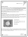
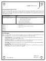
// K1600 // MIDI Converter
User Manual
Hardware Version C
Firmware Version 1.0
August 1, 2010
Kilpatrick Audio
// K1600 // MIDI Converter
2p
Introduction
The K1600 MIDI Converter is a versatile bridge between MIDI equipment and analog modules. Its
outputs are designed to interface with many types of modules, and the method of control can be
adapted to suit your needs. By using a MIDI learning approach to programming, MIDI messages can
be used to assign the outputs quickly. The CV and gate outputs specifically allow different modes of
operation for pitch and gate control, even supporting polyphony.
By using multiple K1600 modules, the MIDI signal can be daisy-chained between modules. This not
only expands the total number of outputs, but also allows polyphonic control of more than two voices.
In this mode the modules work together to assign voices to up to 16 CV/gate output pairs.
Features
•
•
•
•
•
•
•
•
•
•
•
Eurorack (3U) form factor - 12HP width
MIDI to CV, gate, trigger and clock converter
Provides MIDI expansion for other Kilpatrick Audio modules
MIDI soft-thru for daisy-chaining multiple units
Quick programming with MIDI learn function
Multi-channel and split-keyboard support for independent control of different outputs
Polyphonic CV/gate output - duophonic support with a single K1600
Polyphonic mode with 4, 6, 8, etc. voices using multiple K1600s
CV pitch bend support
Four drum trigger outputs
Continuous controllers (CC) assignable to any CV/gate or trigger output
•
•
•
MIDI clock to analog (5V) clock and reset outputs for driving analog sequencers
Trigger, gate, clock, reset outputs: 0V / 5V (positive edge triggered)
CV outputs: -5V to +5V, 1V/octave, trimmable - high precision power supply and 12 bit DACs
ensure tuning stability
Program-change control over various modes
Requires +/-12V (20mA) and +5V (40mA) - 16 pin Doepfer-style power cable used
Designed and made in Canada using high quality parts.
Warranty: 1 year
•
•
•
•
User Manual
Hardware Version C
Firmware Version 1.0
August 1, 2010
© 2010 Kilpatrick Audio
// K1600 // MIDI Converter
3p
Installation and Setup
When installing the K1600 in your modular system, pay close attention to the pinout and direction of
the 16-pin power input cable. As +5V is required, the 10-pin style of power cable is not compatible.
The K1600 contains protection against reverse connection, but please double-check the cable before
switching on the unit. The warranty does not cover damage caused by wrong installation.
If you are using the module with another MIDI device using the internal MIDI cable, connect a 10 pin
ribbon cable between the two units. In this case also observe the correct cable direction.
Warning: DO NOT plug the MIDI cable into the power port, or vice versa.
Output Voltage Trim
The voltage trim on the outputs is factory calibrated into a 100K ohm load. But depending on your
setup you might need to adjust it if the scale tuning is wrong with your oscillators. The multi-turn trim
pot supplied on each output can adjust the tuning over a significant range.
To trim the outputs it is required to enter setup mode on both CV outputs. To do this, click the SELECT
switch until all 4 CV/gate LEDs are flashing in unison. Then place the switch into SETUP mode. In this
mode the gate outputs will pulse and the CV outputs will generate +1.000V.
Output Voltage Trim:
Adjust the output voltage trim with a small
flat screwdriver to achieve the correct scale
span with your VCO.
R28 = CV1 trim
R27 = CV2 trim
Fig. 1 - Output Voltage Trim
Adjust the pot for each output as shown in fig. 1 until you read exactly +1.000V on each output. (you
need a high quality voltmeter to do this) Notes should play perfectly in tune across the entire range. If
this is not so, adjust the voltage to be higher (larger scale span) or lower (smaller scale span) until
you arrive at the correct setting for your oscillator.
User Manual
Hardware Version C
Firmware Version 1.0
August 1, 2010
© 2010 Kilpatrick Audio
// K1600 // MIDI Converter
4p
Physical Installation
You should install the unit in your modular system using all four screw holes. The unit is designed to
be mounted properly to avoid damage to the internal parts when plugging or unplugging cables, or
adjusting the controls.
Connection Warnings
The CV outputs are buffered, low impedance (100 ohm) outputs designed to drive oscillator 1V/octave
inputs with minimal error. You should not attempt to sum the CV outputs with passive multiples. Doing
so will not harm the unit, but will likely not result in the behaviour you expect.
The gate, trigger and clock outputs are 1000 ohm outputs and should not have voltages fed into them
from other units. They are designed to tolerate the input of between -12V and +12V but are meant for
output only. You should be able to sum the signals using passive multiples, but buffered mixers are a
better choice for achieving proper mixing of signals.
User Manual
Hardware Version C
Firmware Version 1.0
August 1, 2010
© 2010 Kilpatrick Audio
// K1600 // MIDI Converter
5p
Usage
To use the K1600 MIDI Converter requires a source of MIDI. This can be a MIDI controller such as a
keyboard, or it may be a MIDI interface connected to a computer and sequencing software. The
routing of MIDI signals from your various instruments is up to you, but the K1600 is equipped to
respond on multiple MIDI channels simultaneously, making it an ideal interface for use with MIDI
sequencers and mergers.
Channel 16 Reserved
One important point is that channel 16 is reserved and cannot be used for normal MIDI assignment.
Reserved functions available on channel 16 can be used to directly control any of the outputs. This
means that the K1600 can be used as a low-level MIDI to voltage converter which includes direct control
over every output, including setting the CV output DACs to any value, producing pulses of different
lengths (timed output pulses) and so on. This is very useful for show automation or special projects that
can benefit from voltage control via MIDI.
Non-volatile Memory
Every output assignment as well as the clock configuration is stored in non-volatile EEPROM inside the
K1600 CPU. This means that the settings will survive power off. To save the EEPROM lifespan, settings
will only be written if they are changed. Thus you are free to update the configuration as often as you
like. The settings are stored immediately after being changed so no special save procedure is needed.
Resetting the Non-volatile Memory
To reset the internal EEPROM to the factory settings, hold down the SELECT switch when powering on
the unit. The EEPROM will be erased and the factory configuration will be restored.
Software Update
Should changes to the K1600 firmware be released, such as feature enhancements or bug fixes, new
firmware can be loaded via the MIDI ports using special PC or Mac software supplied by Kilpatrick
Audio. Please contact Kilpatrick Audio if you have any questions about software updates or wish to file a
bug report.
User Manual
Hardware Version C
Firmware Version 1.0
August 1, 2010
© 2010 Kilpatrick Audio
// K1600 // MIDI Converter
6p
Output Learn Mode
To assign a MIDI message to an output, select the output or pair of outputs using the SELECT switch.
Clicking the SELECT switch will cycle through the available outputs and flash the LEDs to show which
outputs will be assigned. After an output is selected, send the appropriate MIDI message to assign the
output. The SELECT mode will time out after a few seconds if a MIDI message is not received. The types
of messages and the respective behaviour on each output depends on the output type.
After selecting an output mode, setting the SETUP switch will hold the output in learn mode and also
send voltages and pulses out of the selected outputs for testing. This can be used to aid in oscillator
tuning, setting up envelope generator and drum voice trigger sensitivity settings, and so on.
Any MIDI channel (except channel 16) can be used to assign an output. After being assigned, the output
will respond to this channel and type of message only, making it possible to control each output on a
different channel if desired.
Learn Mode Details
•
•
•
•
MIDI Channel 16 – You cannot assign outputs using MIDI channel 16. This channel is reserved for
direct control mode.
Note Assignment – CV outputs only support playing notes from note numbers 12-115. Notes
received outside this range will be ignored.
Continuous Controllers – You cannot assign outputs using controller numbers 122-127. These
are reserved by the MIDI spec and cannot be used.
High-resolution Controllers – Only 7 bit controllers are supported. High-resolution (MSB / LSB)
CC pairs are not supported in learning mode. For precision control of the CV DACs, the direct
control mode on channel 16 can be used.
User Manual
Hardware Version C
Firmware Version 1.0
August 1, 2010
© 2010 Kilpatrick Audio
// K1600 // MIDI Converter
7p
CV/Gate Outputs
The CV/gate outputs are are arranged in pairs. Both CV1 and GATE1 as well as CV2 and GATE2 are
logically paired and will always be assigned together. Additionally, there are three modes which affect
how CV1/GATE1 and CV2/GATE2 work together when assigned in note mode. See the description of each
mode below. CV/gate outputs can be assigned to note, continuous controller (CC) or pitch bend
messages.
Note Modes
In note mode, MIDI note messages are output as pitch voltages on the CV outputs, and gate control on
the gate outputs. There are three ways that outputs can be used:
•
Single Mode – Each CV/gate output pair is used by itself. The CV will output the pitch and the gate
will output the note on/off control. In single mode each pair of outputs can be assigned to the
same or different MIDI channel. To assign single mode, click the SELECT switch until only one
pair of CV/gate LEDs is flashing and then send a MIDI note message. In single mode, notes are
assigned based on a last note priority rule. The last 8 notes pressed will be stored and recalled as
you let go of keys.
•
Split-keyboard Mode – Both pairs of CV/gate outputs are used together and receive on a single
MIDI channel, however they will work in split-keyboard mode by filtering notes above or below a
specific point. To assign split-keyboard mode, click the SELECT switch until both pairs of CV/gate
LEDs are flashing alternately. Then send a MIDI note message. The note sent becomes the split
point. This note or any notes higher will be output on CV2/GATE2 and all lower notes will be
output to CV1/GATE1. In split-keyboard mode, notes are assigned based on a last note priority
rule. For each output, the last 8 notes pressed will be stored and recalled as you let go of keys.
Polyphonic Mode – Both pairs of CV/gate outputs are used together and receive on a single MIDI
channel. In polyphonic mode, the outputs are chosen based on available voice slots. Each slot is
represented by a CV/gate output pair. As more notes are pressed and held down, an additional
CV/gate pair is used for each note. With a single K1600 module, two voices can be played at once,
starting with CV1/GATE1. Through expansion and the use of additional K1600s, up to 16 voices (8
modules) can be played at once. To assign polyphonic mode, click the SELECT switch until both
sets of CV/GATE outputs are flashing in unison. Then send a MIDI note message corresponding to
which pair of voices the K1600 should represent in the polyphonic voice order using the white
keys starting with C4 (MIDI note 60) for voices 1-2, D4 for voices 3-4 and so on. The complete list
of voice assignment notes are shown below:
•
User Manual
Hardware Version C
Firmware Version 1.0
August 1, 2010
© 2010 Kilpatrick Audio
// K1600 // MIDI Converter
8p
Notes for voice assignment in polyphonic voice mode:
◦ C4 (note 60) = Voice 1-2
◦ D4 (note 62) = Voice 3-4
◦ E4 (note 64) = Voice 5-6
◦ F4 (note 65) = Voice 7-8
◦ G4 (note 67) = Voice 9-10
◦ A5 (note 69) = Voice 11-12
◦ B4 (note 71) = Voice 13-14
◦ C5 (note 72) = Voice 15-16
Assign each module for polyphonic mode by setting it to respond to a pair of voices. Voices are
used starting at voice 1, progressing upwards as more notes are played at once.
Pitch Bender Support in Note Modes
In the note modes the pitch bender on the assigned channel affects the pitch of the CV outputs. By
default the bend amount is set to +/-2 semitones. However any bend amount from 1 to 12
semitones can be set independently for both outputs. Use program change commands to set the
bend amount for each output as follows:
•
•
Program change 49-60 – CV1 bend amount (1-12 semitones)
Program change 61-72 – CV2 bend amount (1-12 semitones)
User Manual
Hardware Version C
Firmware Version 1.0
August 1, 2010
© 2010 Kilpatrick Audio
// K1600 // MIDI Converter
9p
Typical Note Mode Setups
Fig. 2 – Single Note Mode
Fig. 3 – Split-keyboard Mode
Fig. 4 – Polyphonic Mode (with multiple K1600s)
Three typical note mode CV/gate setups are shown above. In fig. 2 a single K1600 module sends note
messages from MIDI channel 1 to CV1/GATE1 and from MIDI channel 4 to CV2/GATE2. This is a typical
setup for two monophonic voices to be controlled from a MIDI sequencer, such as a lead sound and a
bass line. Fig. 3 shows a split-keyboard setup where notes on a MIDI channel are sent to CV1/GATE1 if
the note number is 60-115, and CV2/GATE2 if the note number is from 12-59. This is a setup typically
used to control two monophonic voices from a single keyboard controller. Fig. 4 shows a polyphonic
setup with three K1600 modules. In this mode the internal note scheduler on each module controls two
voices using CV1/GATE1 and CV2/GATE2. As more notes are played at once, more outputs are used.
Voices are assigned from VOICE1 to VOICE6 as shown on the drawing. If more than 6 notes are played at
once, the additional notes will not be heard. This scheme allows additional K1600s to be added for more
polyphony. Keep in mind that this setup supports up to 16 notes maximum.
User Manual
Hardware Version C
Firmware Version 1.0
August 1, 2010
© 2010 Kilpatrick Audio
// K1600 // MIDI Converter
10p
Continuous Controller Mode
In continuous controller (CC) mode, the CV/gate outputs are assigned to a continuous controller. The CV
output sends a voltage corresponding to the CC value (from -5V to +5V) and the GATE output sends 0V if
the value is less than 64, or +5V if the value is greater than or equal to 64. This produces a simultaneous
analog and digital output signal. It is not possible to assign different controllers to the CV and gate
outputs.
To assign a CC output to a CV/gate pair, click the SELECT switch until only one pair of CV/gate LEDs is
flashing. (single mode) Then send a CC on the desired channel and it will be assigned.
Pitch Bend Mode
In pitch bend mode, the CV/gate outputs are controlled by pitch bend messages on a channel. Pitch bend
mode works like continuous controller mode, however it differs in that the polarity of the output can be
inverted. If the assignment is made with the pitch bender moving up, the outputs will be assigned in
normal polarity. (The outputs go high as pitch bender is raised.) However if the pitch bender is moved
down during assignment, the outputs will be assigned in inverted polarity. (The outputs go low as the
pitch bender is raised.) This makes is possible to achieve very useful control schemes. In fact, two
CV/gate output pairs can be assigned to a pitch bender on the same channel but in opposite polarities
for inverted, ganged control. Using two VCAs to produce panning effects, or alternately speeding up and
slowing down a pair of LFOs would work well with this kind of configuration.
In pitch bend mode, the gate output is treated differently than in continuous controller mode. In the
centre position, the gate output will always be off, regardless of the output polarity. As the pitch bender
is raised or lowered (depending on the polarity setting) the gate output will turn on. This means that the
gate output can be used as a momentary control. The CV output will work over the entire range,
however. Keep in mind that most controller keyboards do not implement high-resolution pitch benders,
despite the specification allowing for up to 14 bits of resolution. You will likely notice digital steps when
using this mode for pitch or filter cutoff control.
To assign a pitch bender to a CV/gate pair, leave the pitch bender in the centre of travel, then click the
SELECT switch until only one pair of CV/gate LEDs is flashing. (single mode) Then move the pitch bender
either up or down to set the polarity (either normal or inverted) of the assignment.
Trigger Outputs
Trigger outputs are mainly designed to control drum voice modules. Trigger outputs can be assigned to
notes, continuous controller (CC) or pitch bend messages.
Note Mode
In note mode, when a matching Note On message is received by a trigger, the output will pulse high for a
short time. (about 10ms) Held notes are not possible on the trigger outputs. To assign a trigger output,
click the SELECT switch until the desired trigger LED is flashing. Send a note message on the desired
User Manual
Hardware Version C
Firmware Version 1.0
August 1, 2010
© 2010 Kilpatrick Audio
// K1600 // MIDI Converter
11p
channel to assign the output.
Continuous Controller Mode
In continuous controller (CC) mode, a CC message is used to control an output. The output sends 0V if
the value is less than 64, or +5V if the value is greater than or equal to 64. The output will remain on as
long as the CC value is greater than or equal to 64.
To assign a CC output to a trigger output, click the SELECT switch until the desired trigger output LED is
flashing. Then send a CC on the desired channel and it will be assigned.
Pitch Bend Mode
In pitch bend mode the pitch bend channel message is assigned to a trigger output. Similar to the
CV/gate outputs, the polarity of the pitch bend for a trigger output can be set as well.
To assign a pitch bend to a trigger output, click the SELECT switch until the desired trigger output LED is
flashing. Then send either an upward or downward bend to assign the output and set the polarity. In the
centre position the trigger output will be off regardless of the polarity setting. If upward polarity was
assigned, the trigger output will go on as the bender is raised. If downward polarity was assigned, the
trigger output will go on as the bender is lowered.
User Manual
Hardware Version C
Firmware Version 1.0
August 1, 2010
© 2010 Kilpatrick Audio
// K1600 // MIDI Converter
12p
Clock and Reset Outputs
The clock and reset outputs are used to convert MIDI clock messages into pulses that can be used to
drive analog sequencers. MIDI clock ticks received by the K1600 will be output as pulses on the clock
output. The MIDI song stop message will cause the reset output to pulse for a short time. (approx. 20ms)
This can be used to reset analog sequencers when a MIDI sequencer is stopped.
Normally each MIDI clock tick received causes an output pulse on the clock output. There are 24 pulses
per beat in MIDI. It may be desirable to divide the MIDI clock to some lower rate. Divisions from 1-48 are
supported. Sending a program change command of 1-48 to any channel will set the clock division to any
value from 1-48 respectively.
•
Program change 1-48 – Clock output divide amount (1-48)
The clock output will pulse for approx. 5ms. The reset output will pulse for approx. 20ms.
MIDI OUT / THRU Switch
Because the K1600 can act as a MIDI expander for other modules such as the K4815 Pattern Generator,
the MIDI output jack can be used either as a THRU connection (for daisy-chaining more K1600s or other
instruments) or as the MIDI OUT jack for a module connected to the internal MIDI expansion port. If the
MIDI OUT / THRU switch is set to OUT, MIDI received on the internal MIDI port will be output on the MIDI
OUT jack. In the THRU mode, MIDI input to the K1600 will be relayed through the unit. Note that this is a
soft-thru connection so that the K1600 can also send its own data from the THRU port. There will be a
short delay in relaying messages which will accumulate as more units are daisy-chained. (about 1-2ms
per module) Also note that SYSEX messages sent through the K1600 cannot have a payload greater than
64 bytes. For software updates or bulk dumps to down-stream equipment, please plug this equipment
directly into the source and not pass it through the K1600 when performing these functions.
Using the MIDI Expander Port
The K1600 can be used as a MIDI breakout board for modules such as the K4815 Pattern Generator. A 10
pin IDC ribbon cable must be connected between the two modules. Observe the correct polarity of the
cable, and connect it to X11 on the K1600 and to the appropriate port on the other module.
The connected module will receive all MIDI messages received on the MIDI IN jack of the K1600. If you
wish to get MIDI output from the connected module, move the MIDI OUT switch to OUT. This routes MIDI
data from the connected module to the MIDI OUT jack on the K1600. Note that the MIDI THRU function of
the K1600 cannot be used when the connected module is using the MIDI OUT jack.
The setup function on the K1600 can be used to place the connected module into its SETUP / TEST
mode. Click the SELECT switch until both MIDI LEDs are flashing. Place the switch in SETUP mode to
hold the other module in its SETUP / TEST mode. This can be used to enable MIDI learn mode and
calibration mode on the connected module.
User Manual
Hardware Version C
Firmware Version 1.0
August 1, 2010
© 2010 Kilpatrick Audio
// K1600 // MIDI Converter
13p
MIDI Implementation
Note On Messages
Note On messages are supported in CV/gate modes as well as trigger output modes. For triggers the
output only stays on for 10ms regardless of whether a note is held down on the keyboard.
Note Off Messages
Note Off messages are only used in CV/gate mode to control the gate outputs. For triggers this type of
message is ignored.
Pitch Bend Messages
Pitch bend messages are used both for note bending when using the CV outputs in note mode, as well as
for output control when pitch bend messages are assigned directly to outputs.
In note mote, the pitch bend affects the overall note pitch depending on the setting of the pitch bend
amount. (default = 2 semitones) The amount for each of the CV outputs can be set independently from 1
to 12 semitones.
When the pitch bender is assigned to a CV/gate output pair or a trigger output, the value of the bender
determines the voltage of the output (CV output) or whether an output is on or off. (gate and trigger
outputs)
Program Change Commands
Program change commands are used to configure specific aspects of the system. They are received on
any channel regardless of the output assignments. This makes it possible to control system-wide
configuration from any MIDI channel.
Program Change Value
Action
Program change: 1-48
Output clock divider: 1-48 = division of 1-48 (default = 1)
Program change: 49-60
CV1 pitch bend amount: 49-60 = 1-12 semitones (default = 2)
Program change: 61-72
CV2 pitch bend amount: 61-72 = 1-12 semitones (default = 2)
Continuous Controller (CC) Messages
Continuous controllers can be assigned to CV/gate outputs or trigger outputs. Any continuous controller
number from 0-121 can be assigned to an output.
User Manual
Hardware Version C
Firmware Version 1.0
August 1, 2010
© 2010 Kilpatrick Audio
// K1600 // MIDI Converter
14p
Direct Control Mode (Channel 16 Only)
The Direct Control Mode on channel 16 uses continuous controller messages to control any of the
outputs. This includes the ability to set the CV outputs to any voltage, as well as the ability to turn on, off
or pulse any of the trigger, clock and reset outputs. Pulsed output will cause a timed output pulse that is
controlled by the K1600.
Direct Control Mode CC
Action
CV1 DAC: 16 (MSB), 48 (LSB)
CV2 DAC: 17 (MSB), 49 (LSB)
CV1 / CV2 DAC Control:
• Use the MSB and LSB bytes to set 12 bits of resolution.
◦ MSB = top 7 bits (right justified)
◦ LSB = lower 5 bits (left justified)
• Value 0 = highest output voltage
• Value 4095 = lowest output voltage
• When trimmed, approx. 408 steps / volt
GATE1: 18
GATE2: 19
TRIG1: 70
TRIG2: 71
TRIG3: 72
TRIG4: 73
CLOCK: 74
RESET: 75
Timed control of gate, trigger and clock outputs:
• Value 0 = off
• Value 1-126 = timed pulse (approx. 2-252ms)
• Value 127 = on
Clock Messages
Clock messages affect the clock and reset outputs. The clock output rate is determined by the clock
divider setting (default = 1) which can be changed with program change commands.
•
•
•
•
•
Clock Timing Tick – If the clock divider is set to 1, each clock timing tick recevied will cause an
output pulse on the clock output. (approx. 5ms)
Song Position Pointer – The song position pointer is used to adjust when the next output clock
pulse will be sent and is only effective when the clock is being divided.
Start Song – Resets the clock counter to 0. This is only effective when the clock is being divided.
Continue Song – Does not reset the clock counter to 0.
Stop Song – Causes the reset output to pulse. (approx. 20ms) This is used primarily for resetting
analog sequencers when the sequence is stopped.
User Manual
Hardware Version C
Firmware Version 1.0
August 1, 2010
© 2010 Kilpatrick Audio
// K1600 // MIDI Converter
15p
SYSEX Messages
System Exclusive (SYSEX) messages are used by Kilpatrick Audio modules for vendor-specific
commands that are not part of the MIDI spec. Some are used internally for software updates and
debugging. But some messages can be used for setup and control of the system by users. The following
outlines how this can be used.
System Configuration
To aid in setting specific configuration without the use of the front panel SELECT and SETUP switches,
all system configuration can be set via a SYSEX message. This can be useful to reconfigure the K1600
from a MIDI sequencer or patch librarian software. Please note that setting the configuration using this
command will overwrite all EEPROM settings stored in the unit, just as if the settings were made from
the front panel of the K1600.
•
Set system configuration:
◦ 0xf0 0x00 0x01 0x72 0x40 0x02 [24 setting bytes] 0xf7
•
The meaning of the 24 setting bytes are as follows:
Byte Number / Meaning
Values
Byte 1 – CV1 map
0 = unassigned
1 = note mode
2 = CC mode
3 = pitch bend mode
Byte 2 – CV2 map
0 = unassigned
1 = note mode
2 = CC mode
3 = pitch bend mode
Byte 3 – CV1 channel
0-14 = MIDI channel 1-15 (channel 16 reserved)
Byte 4 – CV2 channel
0-14 = MIDI channel 1-15 (channel 16 reserved)
Byte 5 – CV1 value
CC mode: controller number (0-121)
pitch bend mode: 1 = normal, 0 = inverted
Byte 6 – CV2 value
CC mode: controller number (0-121)
pitch bend mode: 1 = normal, 0 = inverted
Byte 7 – TRIG1 map
0 = unassigned
1 = note mode
2 = CC mode
3 = pitch bend mode
Byte 8 – TRIG2 map
0 = unassigned
1 = note mode
User Manual
Hardware Version C
Firmware Version 1.0
August 1, 2010
© 2010 Kilpatrick Audio
// K1600 // MIDI Converter
2 = CC mode
3 = pitch bend mode
Byte 9 – TRIG3 map
0 = unassigned
1 = note mode
2 = CC mode
3 = pitch bend mode
Byte 10 – TRIG4 map
0 = unassigned
1 = note mode
2 = CC mode
3 = pitch bend mode
Byte 11 – TRIG1 channel
0-14 = MIDI channel 1-15 (channel 16 reserved)
Byte 12 – TRIG2 channel
0-14 = MIDI channel 1-15 (channel 16 reserved)
Byte 13 – TRIG3 channel
0-14 = MIDI channel 1-15 (channel 16 reserved)
Byte 14 – TRIG4 channel
0-14 = MIDI channel 1-15 (channel 16 reserved)
Byte 15 – TRIG1 value
note mode: note number
CC mode: controller number (0-121)
pitch bend mode: 1 = normal, 0 = inverted
Byte 16 – TRIG2 value
note mode: note number
CC mode: controller number (0-121)
pitch bend mode: 1 = normal, 0 = inverted
Byte 17 – TRIG3 value
note mode: note number
CC mode: controller number (0-121)
pitch bend mode: 1 = normal, 0 = inverted
Byte 18 – TRIG4 value
note mode: note number
CC mode: controller number (0-121)
pitch bend mode: 1 = normal, 0 = inverted
Byte 19 – clock divider
clock divider amount: 1-48 = divide by 1-48
Byte 20 – voice mode
0 = single
1 = split
2 = poly
Byte 21 – voice split
split voice mode split point: note number
Byte 22 – voice unit
polyphonic voice mode unit number: 0-7 = unit 1-8
Byte 23 – voice bend CV1 amount
CV1 bend amount: 1-12 = 1-12 semitones
Byte 24 – voice bend CV2 amount
CV2 bend amount: 1-12 = 1-12 semitones
Note: In split-keyboard or polyphonic mode, only CV1 bend amount is used.
User Manual
Hardware Version C
Firmware Version 1.0
August 1, 2010
© 2010 Kilpatrick Audio
16p
// K1600 // MIDI Converter
17p
Internal Connector Pinouts
To assist in making correct connections, and to aid in the creation of compatible adaptor circuits, the
internal pin headers are documented here. Please note that X15 is a factory setup connector only and
should not be used. Both X11 and X12 connectors are 0.100" pitch pin headers. Standard IDC ribbon
cables can be connected.
X11 – MIDI/Test Connector:
1.
2.
3.
4.
5.
6.
7.
8.
9.
10.
GND
GND
GND
GND
TEST (output for ext. module)
MIDI TX (output to ext. module)
N/C
MIDI RX (input from ext. module)
N/C
N/C
X12 – Power:
1.
2.
3.
4.
5.
6.
7.
8.
9.
10.
11.
12.
13.
14.
15.
16.
-12V input
-12V input
GND
GND
GND
GND
GND
GND
+12V input
+12V input
+5V input
+5V input
N/C
N/C
N/C
N/C
Support and Additional Information
Please contact Kilpatrick Audio with additional questions about the K1600 MIDI Converter. We will do
our best to help you make the most of your MIDI converter and welcome your suggestions as to
software improvements or ideas for features on new products. Contact: [email protected]
User Manual
Hardware Version C
Firmware Version 1.0
August 1, 2010
© 2010 Kilpatrick Audio
// K1600 // MIDI Converter
K1600 MIDI Converter
Function
MIDI IMPLEMENTATION CHART ver.1.0
18p
2010-08-01
Transmitted
Recognized
Remarks
none
1-16 (configured)
none
1-16 (configured)
Use SELECT and SETUP to
assign receive channels.
X
X
X
X
X
X
0-127
0-127
Notes 12-115 in voice
mode.
X
X
Ignored in all modes.
X
X
X
X
Ignored in all modes.
Pitch Bend
O
O
Used in all modes,
depending on output
assignment.
Control Change
O
O
Control changes are
supported according to the
output assignments or
direct mode control.
Prog
Change True #
O
0
See documentation for
program change usage.
System Exclusive
O
O
See documentation for
SYSEX usage.
System
Common
Song Position
Song Select
Tune Request
O
X
X
O
X
X
System
Realtime
Clock
Commands
O
O
O
X
Aux
Messages
Local On/Off
All Notes Off
Active Sensing
System Reset
X
X
X
X
X
X
X
X
Basic
Default
Channel Changed
Mode
Default
Messages
Altered
Note Number
Velocity
After
Touch
Keys
Ch's
Software update specification available upon request. Implemented by Kilpatrick
Audio update software as supplied to customers.
Notes
User Manual
Hardware Version C
Firmware Version 1.0
August 1, 2010
© 2010 Kilpatrick Audio