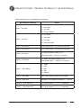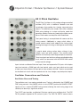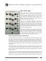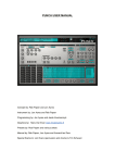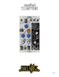
1
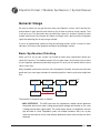
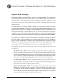
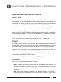
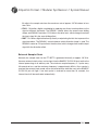
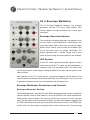
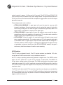
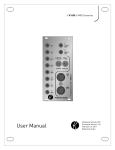
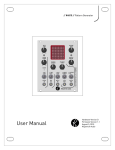
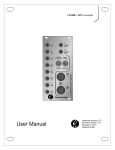
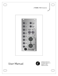
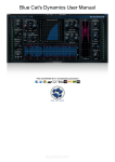
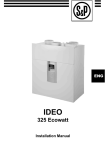
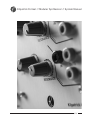
Kilpatrick Format // Modular Synthesizer // System Manual
// i //
Kilpatrick Format // Modular Synthesizer // System Manual
Contents
Introduction.................................................................................................. 1
General Usage.............................................................................................. 2
Basic Synthesizer Patching......................................................................................2
Signals and Voltages.................................................................................................4
Enclosure and Module Installation...........................................................................6
Patch Cables.............................................................................................................7
Modules........................................................................................................ 8
K1 // Mixer Interface.................................................................................................8
K2 // Pitch Oscillator...............................................................................................14
K3 // Digital Effects.................................................................................................16
K4 // Envelope Modulator.......................................................................................19
K5 // Filter Amp.......................................................................................................21
Additional Information................................................................................ 23
// ii //
Kilpatrick Format // Modular Synthesizer // System Manual
Introduction
The Kilpatrick format is a new kind of modular synthesizer system for players that demand
something better, different and inspiring. Designed by Andrew Kilpatrick, the Kilpatrick
format represents a new generation of modular music making by offering the right
combination of look and feel, playability, excellent circuit design, and the perfect blend of
old and new concepts that make the system easy and fun to use.
The Kilpatrick format system aims to provide all the building blocks for experimental sound
production in a way that is incredibly intuitive and enjoyable. Discovering new sounds
should be something that happens in every session. After several years of research and
experimentation, the Kilpatrick format was chosen. Containing new design ideas and the
best of traditional modular synthesizer concepts, the format aims to offer the best user
experience possible.
We hope that you enjoy using your Kilpatrick format system for many years to come!
Kilpatrick Format Features:
• 4U (7”) panel height - each panel offers close to 30 in. of panel space
• Simple plug and play module installation - rearranging a system or adding new
modules is easy
• Universal use of banana cables for patching of audio, CV and pulse/gate signals high quality cables are available in a variety of colors and lengths
• Color-coded jacks indicate different signal functions and direction
• Separate analog and digital grounds used for low noise signal returns - plenty of
power available for digital modules
• Total cabinet depth of less than 3” permits table top or rack mounting
• High quality brushed anodized panels are rugged and feature clean, futuristic graphics
• All modules and systems are hand-assembled and built-to-order in our downtown
Toronto workshop
// 1 //
Kilpatrick Format // Modular Synthesizer // System Manual
General Usage
We want to make sure you get the most from your Kilpatrick system. You’ll find that this
manual doesn’t offer specific patch ideas or tips on how to achieve certain sounds. That
is left up to you. This document aims to outline the various ins and outs (literally) of each
module and what all the controls do. Below we’ll begin with a basic overview of general
signal and patching tips to help you get started.
If you’re an experienced synthesist then the following section will be a review of basic
concepts. Feel free to skip ahead to the Signals and Voltages section.
Basic Synthesizer Patching
When you first set up your system you’ll need to make some connections before any
sound will come out. The modular aspect of the system means that there are lots of tools
at your fingertips, powered up and ready to go, but it’s up to you to connect them in some
sort of useful way.
Many keyboard synthesizers are built with a fixed patch internally, and you can make that
patch too if you want to get started with something familiar. A basic synth patch might look
like:
OUTPUT
OSCILLATOR
PITCH
FILTER
TIMBRE
VCA
MIXER
VOLUME
CONTOUR
LFO
MIDI INTERFACE
GATE
ENVELOPE
The modules in the patch work as follows:
• MIDI INTERFACE - The MIDI input from the keyboard or another device generates
information about which note is being played (pitch voltage) and whether or not a key
is being pressed down (gate signal). The setup shown above is monophonic and can
play one note at a time. Polyphonic synths use multiple oscillators, filters, etc. to play
more than one note at at time, and software determines which notes will play on which
hardware.
// 2 //
Kilpatrick Format // Modular Synthesizer // System Manual
• OSCILLATOR - The oscillator generates a waveform, usually a basic waveform like a
sawtooth, pulse wave, etc. but sometimes more complex waves like sampled waves.
The output is generated all the time, the pitch determined by a voltage from the MIDI
interface. In analog synths this voltage is usually decided as something like 1V per
octave. That means for every 1V increase in the pitch voltage, the output frequency
will increase by 1 octave. (double in frequency)
• FILTER - The filter changes the timbre of the sound by applying some kind of frequencydependent transformation on it. The most common filter type is the low-pass filter,
which cuts off high frequency sounds. Usually the cutoff frequency is adjustable by a
voltage.
• LFO - The low-frequency oscillator (LFO) generates a low-frequency signal, usually
a triangle or sine wave. The LFO can usually make signals from about 1 cycle per
minute, up to maybe 40Hz or so. The LFO is used to modulate some parameter of the
sound to create a constantly evolving and changing sound. In the example above the
LFO is used to modulate the filter cutoff frequency.
• VCA - The voltage-controlled amplifier (VCA) can adjust the volume of a sound from
muted to full volume under voltage control. The VCA is the necessary component for
making it possible to have sounds that turn on and off when you press and release
keys on the keyboard.
• ENVELOPE - The envelope generator takes gate (on/off) voltages from the MIDI
interface and makes smoothly changing voltages which fade up and down when a
key on the keyboard is pressed or released. This is usually used to turn the volume of
a sound up and down. Envelopes can also be used as sources of modulation in many
places where you might consider an LFO.
• MIXER - Most synths contain a mixer section just before the sound comes out to a
line output or headphone jack. In a polyphonic setup this is used to mix all the notes
together. It also adjusts the master volume, and often contains circuitry for adding
reverb, delay or chorus effects to the final sound.
This is an overly simplified explanation, but this is the general idea behind most synthesizers.
Nearly all digital or analog synthesizers follow a signal flow similar to what was described
above. But for experimental sound creation or ultimate flexibility, breaking from this
traditional type of patch will open the doors to a world of sonic possibilities.
In a modular system you can build a traditional synth patch like the one shown above, or
you can patch in a totally different way to create sounds never heard before.
// 3 //
Kilpatrick Format // Modular Synthesizer // System Manual
Signals and Voltages
Everything patchable in the Kilpatrick system is voltage-controlled. This concept of
representing control parameters with voltages was what made synthesizers practical for
musicians back in the 1960s. And now with the rebirth of the modular synthesizer in the
present day we can once again experience the flexibility that player-patchable control
signals presents.
We often speak of CV (control voltage) in which we usually mean a signal that affects
a performance parameter, instead of the actual audio signals being generated. In the
Kilpatrick format audio and CV signals are interchangeable, and the only difference when
thinking about patching is the intended function. CV signals are often held at steady DC
voltages, or set up to be slowly changing. Audio signals are usually faster changing signals
or percussive impulses. But there is no limit to using CV and audio signals interchangeably.
You should always monitor the output with speakers or headphones connected to one of
the mixer outputs. Connecting directly to a module output might cause DC voltages to
be sent to your headphones or speakers which could damage them. Unlike most audio
equipment, the inputs and outputs on the Kilpatrick system are often designed to work all
the way down to DC. The headphone and line out jacks are designed to block DC.
The Kilpatrick system uses four types of jacks which are color coded to make them easy
to distinguish:
• CV / Audio Output - GRAY - Control voltages and audio signals come out of gray jacks.
These are normally in the range of -5V to +5V. Most outputs are fed through 1K resistors
to make them protected from short circuits. The exception is pitch outputs from MIDI
to CV converters, which are fed through 100 ohm resistors to provide better tuning
accuracy. You should avoid shorting outputs to the chassis or external equipment.
• CV / Audio Input - BLACK - Control voltages and audio signals go into black jacks. All
black inputs have an input resistance of 20K-50K, with the exception being oscillator
pitch inputs which have an input resistance of 100K.
• Pulse and Gate Output - RED - Pulse, gate and clock outputs and various other
digital type of signals come out of red jacks. These are nominally +5V when on, and
0V when off. They are all fed out through 1K resistors. Pulse and gate output signals
can be fed into CV or audio inputs, but the signal will only change from the mid point
to the maximum value when the output turns on and off.
// 4 //
Kilpatrick Format // Modular Synthesizer // System Manual
• Pulse and Gate Inputs - WHITE - Pulse, gate and clock inputs go into white jacks.
These type of inputs have a resistance of 20K and generally detect any voltage greater
than about +1V. Some inputs like oscillator sync inputs might require a fast-changing
signal like a ramp or pulse wave to trigger. Any range of input voltage can be input to
these jacks making it possible to trigger this type of input from an audio or CV signal.
Warning: The only thing to keep in mind when patching is that outputs should not
connect to other outputs. Although it may be possible to connect two outputs together
to achieve passive mixing, it is not recommended to do this as it can overload the
outputs and may cause damage to the module.
// 5 //
Kilpatrick Format // Modular Synthesizer // System Manual
Enclosure and Module Installation
Enclosure Setup
The smallest size of one module is called a space and occupies a quarter rack width.
Larger modules may occupy two or more spaces. An enclosure generally provides four
spaces and fits into a 19” equipment rack. Other sizes such as five or six spaces can be
custom ordered. Rack ears are used for rack mounting, and stacking brackets are used to
attach two enclosures together for table-top use.
Enclosures can be ordered as active or passive. Active enclosures take power from an
external power supply and generate power for modules internally. Passive enclosures take
power from an active enclosure to add additional modules to the same power supply. An
active enclosure can power approximately 8-12 modules.
When using multiple active enclosures together in the same system it is necessary to
connect a ground cable between systems. Banana sockets are provided on each enclosure
for this purpose. Connect a short banana cable between the systems and always ensure it
is in place before powering up your system. Only connect one of the enclosures to external
equipment such as mixers or amplifiers to prevent ground loops.
Power Supply
The Kilpatrick format system uses a single 15V regulated switching power supply to feed the system.
The power input is located on the back of an active enclosure. Only use the included 15V regulated
power supply for powering the system. Use of other types of power supplies could damage the system.
Module Installation
Modules use a plug-and-play system and requires no internal cables. A single captive
screw is used to secure the module to the enclosure. Never install or remove modules
with power applied!
To remove a module:
• Power down the system
• Loosen the captive screw with the included 2.5mm hex key
• Plug a banana cable into two jacks near the top or bottom of the module
• Grip the banana plugs and gently pull the unit out at one end
• Gently lift the module up out of the enclosure until the internal connectors are completely unplugged
// 6 //
Kilpatrick Format // Modular Synthesizer // System Manual
To install a module:
• Power down the system
• Set the module into the internal connectors and make sure the module is aligned
correctly in the enclosure
• Gently press straight down to seat the module in the enclosure
• Use the included 2.5mm hex key and turn the captive screw counter-clockwise until
a small click is heard
• Turn the captive screw clockwise until it is finger tight -- Do not over-tighten the screw
or you could damage the module
Patch Cables
All patch cables used in the Kilpatrick system are of the 4mm banana type. We supply an
assortment of colors and lengths with each new system and can offer additional cables
upon request. All patch cables supplied are high quality Pomona brand B-type stacking
banana cables. We use only Emerson Johnson banana jacks on modules. This combination
provides very solid connections, and the stacking function is incredibly useful. Even if
plugs are not inserted all the way they can still make excellent contact, making it easy to
try out patch ideas just by touching the plug to various points in the system.
We offer the following unique patch cable color and length combinations:
• 12” GRAY
• 12” RED
• 12” YELLOW
• 18” BLACK
• 18” GREEN
• 18” ORANGE
• 24” BLUE
• 24” BROWN
• 48” VIOLET
// 7 //
Kilpatrick Format // Modular Synthesizer // System Manual
Modules
K1 // Mixer Interface
The K1 Mixer Interface module is a combination of a high
quality five channel audio mixer and MIDI to CV converter.
The mixer is designed for high level signals from other
modules and offers both an AUX send for use with effects,
and dual stereo outputs on banana and mini jacks, as well
as a headphone amplifier with dedicated volume control.
Mixer Section
The mixer circuit incorporates high quality low-noise
inputs on banana jacks. Three mono channels and one
stereo channel all contain input level indicators and input
level controls. The stereo channel offers an AUX send
level control which sends a post-input level blend of the
left and right channels to the AUX output.
The mono inputs offer level controls, a post-input level
AUX send, as well as a pan control. Channel 5 offers a CV
input for panning instead of a pan control.
The master output contains a stereo level control and a pair of banana jacks suitable for
connection to other modules or daisy-chaining several mixers. A pair of mini jacks offer
line-level signals that can be output to external audio equipment. Signal level indicators
show the levels at the output jacks and sense the levels after the MASTER volume control.
A ground jack provides access to the analog ground on the system.
A dedicated headphone amplifier provides a stereo output on a mini jack with a dedicated
level control. This output can also be used for powered speakers or stereo recorders that
work more conveniently with stereo mini cables.
MIDI Interface Section
The K1 also contains a small but useful MIDI to CV converter. Built on the success of the
K1600 MIDI Interface, the MIDI to CV converter on the K1 supports a number of useful MIDI
// 8 //
Kilpatrick Format // Modular Synthesizer // System Manual
to voltage conversions, plus a MIDI THRU jack for daisy-chaining. Outputs can be assigned
to note, control change and pitch bend messages. Note playing modes include single
(mono) mode, split keyboard mode, two-voice polyphonic mode, which is expandable up
to 16 voices with additional modules, Arp Odyssey-style duo-phonic mode, and single
(mono) mode with velocity output on the second CV output jack.
Outputs are programmed by pressing the SET button to select the output mode to program
and then sending a MIDI message to the unit. The MIDI channel, output type and other
parameters are stored automatically in the module and restored at power-on.
Mixer Interface Connections and Controls
Mixer Section
Audio signals are input on IN jacks 1-5. Jacks 1 and 2 are a stereo pair and automatically
wired to output to L and R respectively. Jacks 3, 4 and 5 are mono inputs.
LEVEL 1/2 controls the input level of the stereo input. LEVEL 3, 4 and 5 are used to control
the input from the mono channels. Signal indicators on each channel light regardless of
the level control setting. This can be used to detect if there is a signal present on an input
without having to raise the input level.
Each input has an AUX control. AUX 1/2 sends a mix of inputs 1 and 2 to the AUX OUT
jack. Each mono channel also has a AUX send which will send to the AUX OUT jack. Note
that the AUX controls receive a signal after the input level adjustment. (post-fader) If you
turn down an input level control the AUX control signal will also be turned down.
Channels 3, 4 and 5 support panning. Channels 3 and 4 have PAN controls which position
the signal between the left and right channels on the output. Channel 5 contains a CV input
instead of a panel control. Inputting a CV signal of between -5V and +5V will pan the signal
from fully left to fully right.
The MASTER LEVEL control affects the output signal level on the L and R banana and
minijacks. The PHONES LEVEL control affects the output level on the PHONES jack. Both
output level controls work independently.
MIDI Interface Connections
The MIDI IN jack received MIDI signals from a keyboard or other equipment. Signals input
to the MIDI IN jack are repeated on the MIDI THRU jack.
// 9 //
Kilpatrick Format // Modular Synthesizer // System Manual
The CV / GATE jacks output a variable voltage (CV) and gate signal (GATE) in response to
MIDI input signals. The CV and GATE jacks always operate together in pairs.
To set up the MIDI interface, press the SET button to select the correct programming mode
by observing the GATE1 and GATE2 indicators. Then send the correct MIDI message to
program the outputs. The settings are stored internally and restored when the module is
powered on.
Note: Channel 16 is reserved and cannot be used for programming.
MIDI Setup Modes
The outputs are assigned by pressing the SET button until the correct GATE indicator
flashing pattern is observed, and then sending a MIDI message to assign the outputs. The
K1 automatically learns the MIDI channel and other parameters based on the setup mode.
Press the SET button to cycle through the setup modes. If no MIDI message is detected
within several seconds no change is made to the current setting.
Single (Mono) Mode - GATE 1 indicator flashes (CV1 / GATE1 assign) or GATE 2
indicator flashes (CV2 / GATE2 assign)
Single Mode provides monophonic playing on a single CV / GATE output pair. When
programming, if you send a note message the MIDI channel will be set and pitch
voltages will be output on the CV jack, and gate (note on/off) will be output on the
GATE jack. Last-note priority is used and the last 8 notes pressed will be stored and
recalled as notes are pressed and released.
If you send a CC message when programming, the sent CC number will be output as
a variable voltage on the CV jack. The GATE jack will output an on/off signal based on
whether the CC level is above or below 50%.
If you send a pitch bend message when programming the CV output jack will output
a voltage corresponding to the pitch bender position, and the GATE output jack will
be on if the bender is raised, or off otherwise. If you bend down instead of up during
programming the polarity of the CV signal and GATE response level will be inverted.
Split Keyboard Mode - GATE 1 and 2 indicators flash alternating
In split keyboard mode both pairs of CV / GATE jacks work together to provide a dual
monophonic setup on the same MIDI channel. The note sent to program determines
the lowest note of the upper half (CV 2 / GATE 2) of the keyboard. Last-note priority
// 10 //
Kilpatrick Format // Modular Synthesizer // System Manual
is used and the last 8 notes pressed on each half of the keyboard will be stored and
recalled as notes are pressed and released.
Polyphonic Mode - GATE 1 and 2 indicators flash together
Polyphonic mode makes it possible to play more than one note at a time and have voices
automatically assigned to different outputs as in a polyphonic synthesizer. Multiple K1
units (theoretically up to 8) can be used together for up to 16 voices of polyphony.
Practically speaking 4-6 is probably the maximum number which is reasonable.
While programming, the key pressed sets the voice unit number. This tells the K1 which
pair of voices it is responsible for playing. Press the white keys from C4 (middle C) to C5
to assign voice unit 1-8. Always start with voice unit 1 and add more units depending
on the number of K1s you are using.
Voice unit 1 will produce voices 1 and 2. Voice unit 2 will produce voices 3 and 4, and
so on. As you hold down more keys more voices will be assigned. Releasing a key will
free up a lower numbered slot and the next key pressed will produce an output on this
free voice.
Arp Mode - GATE 1 indicator flashes and then GATE 2 indicator comes on
Arp mode emulates the duo-phonic behavior of the Arp Odyssey synthesizer and offers
a nice combination of mono and poly playing with only two oscillators. When a single
note is being played both CV and GATE output pairs will play in unison. Due to small
analog variations in the CV output and oscillators, a rich chorused sound will be heard
when playing a single note at a time. When a second note is pressed the CV 2 / GATE 2
pair will split off and play the second note. If additional notes are played, monophonic
last-note priority is applied to the second voice while CV 1 / GATE 1 hold the first note
pressed down.
Velocity Mode - GATE 1 indicator flashes and then GATE 2 indicator fades up
Velocity mode offers monophonic playing with last-note priority on CV 1 / GATE 1 while
the velocity of each last note played is output as variable voltage on CV 2. This allows
expressive playing on a touch-sensitive keyboard. The velocity voltage can be used in all
kinds of ways: adjust the volume, affect the speed of an LFO or filter cutoff frequency, etc.
// 11 //
Kilpatrick Format // Modular Synthesizer // System Manual
Pitch Bend Range
When in a note mode the pitch bend range of CV1 or CV2 can be adjusted. Send a MIDI
program change on either CV1 or CV2 assigned channels to adjust the bend range from
1 to 12 semitones. Program change 1-12 selects bend range of 1-12 semitones for CV1.
Program change 13-24 selects bend range of 1-12 semitones on CV2. Pitch bend range
for CV2 is only used in single mode.
Direct Control Mode (Channel 16 Only)
The Direct Control Mode on channel 16 uses continuous controller messages to control
any of the outputs. This includes the ability to set the CV outputs to any voltage, as well as
the ability to turn on or off the GATE outputs.
Direct Control Mode CC
Action
CV1 / CV2 DAC Control:
• Use the MSB and LSB bytes to set 12 bits of resolution.
CV1 DAC: 16 (MSB), 48 (LSB)
CV2 DAC: 17 (MSB), 49 (LSB)
ºº MSB = top 7 bits (right justified)
ºº LSB = lower 5 bits (left justified)
• Value 0 = lowest output voltage
• Value 4095 = highest output voltage
Control of gate outputs:
GATE1: 18
• Value 0-63 = off
GATE2: 19
• Value 64-127 = on
SYSEX Messages
System Exclusive (SYSEX) messages are used by Kilpatrick Audio modules for vendorspecific commands that are not part of the MIDI spec. The K1 MIDI interface channel
and mode assignments can be sent in a single SYSEX message. This can be used by
sequencing software to reset the interface to a known setting when loading a song.
SYSEX packet format:
0xf0 0x00 0x01 0x72 0x43 0x02 [11 setting bytes] 0xf7
// 12 //
Kilpatrick Format // Modular Synthesizer // System Manual
The meaning of the 11 setting bytes are as follows:
Byte Number / Meaning
Values
0 = unassigned
Byte 1 - CV1 Map
1 = note mode
2 = CC mode
3 = pitch bend mode
0 = unassigned
Byte 2 - CV2 Map
1 = note mode
2 = CC mode
3 = pitch bend mode
Byte 3 - CV1 Channel
0-14 = MIDI channel 1-15 (channel 16 reserved)
Byte 4 - CV2 Channel
0-14 = MIDI channel 1-15 (channel 16 reserved)
Byte 5 - CV1 Value
CC mode: controller number (0-121)
pitch bend mode: 1 = normal, 0 = inverted
Byte 6 - CV2 Value
CC mode: controller number (0-121)
pitch bend mode: 1 = normal, 0 = inverted
Byte 7 - Voice Mode
0 = single
1 = split
2 = poly
3 = arp
4 = velocity
Byte 8 - Voice Split
split voice mode split point: note number
Byte 9 - Voice Unit
polyphonic voice mode unit number: 0-7 = unit 1-8
Byte 10 - Voice Bend CV1
CV1 bend amount: 1-12 = 1-12 semitones
Byte 11 - Voice Bend CV2
CV1 bend amount: 1-12 = 1-12 semitones
// 13 //
Kilpatrick Format // Modular Synthesizer // System Manual
K2 // Pitch Oscillator
The K2 Pitch Oscillator is a fully analog voltage-controlled
oscillator (VCO) with a traditional sawtooth core and
waveshapers that provide sine, triangle, ramp and pulse
outputs. Two different pulse modes offer either standard
PWM pulse shaping or a unique multi-pulse mode that
generates different timbres by producing multiple narrow
pulses. Both modes can be pulse width modulated.
Front panel tuning is accomplished with coarse and fine
tuning controls. Additionally a range switch allows a
second coarse control to be added to the tuning signal
allowing two ranges of tuning, or offering even more tuning
range.
A special blend mixing section allows mixing of sine,
triangle, ramp and pulse outputs. Two controls blend
between sine and ramp, and triangle and pulse waveforms.
These two signals are fed into a voltage controlled blending
circuit which can be control with the BLEND MIX control
or input control voltage.
Inputs include a calibrated V/octave input, linear and exponential CV inputs with bi-polar
input level controls, a PWM input with level control, and a sync input which can be used
to hard sync the oscillator with input pulses from another oscillator. Outputs are provided
for the blend mix circuit and also separate outs for sine, triangle, ramp and pulse outputs.
Oscillator Connections and Controls
Oscillator Core and Tuning
The oscillator core is an analog sawtooth core. Tuning is affected by the COARSE and
FINE tuning controls. If the RANGE switch is in the OFFSET position the RANGE OFFSET
control acts as a second COARSE tuning control, allowing the main tuning range to be
shifted up or down by a significant amount.
The V/OCT input provides a calibrated 1V/octave control over oscillator pitch. The EXP
FM IN provides exponential FM control of pitch. The EXP FM DEPTH control affects
// 14 //
Kilpatrick Format // Modular Synthesizer // System Manual
the scaling of the input and can be set to either + or - so that the input signal can be
inverted. (increasing voltage causes decreasing pitch) The LIN FM IN and LIN FM DEPTH
control works similarly except that the pitch change is linear with input voltage instead of
exponential.
Inputting a fast-changing waveform like a pulse wave into the SYNC input will reset the
oscillator core to the starting position. This can be used to create unusual timbres by
driving it from a second oscillator.
PWM Section
The PWM section generates the PULSE output. The PWM OFFSET control selects the
duty cycle of the pulse waveform. PWM IN and PWM DEPTH allow voltage control of the
pulse duty cycle.
Waveshaper Outputs
The signal from the oscillator core is processed by various analog waveshaping sections
before being output on the four main output jacks. The nominal output level is 10Vp-p
except the pulse output which is intentionally slightly lower in amplitude. The jacks output
the following signals:
• RAMP OUT - A processed version of the internal ramp signal from the oscillator core
comes out of the RAMP OUT jack.
• TRIANGLE OUT - The triangle signal is generated from the ramp signal using an
analog waveshaper. This signal comes out of the TRIANGLE OUT jack.
• SINE OUT - A smoothed version of the triangle signal is produced to be somewhat
sine-like. It is not a low-distortion sine wave, but has a soft and interesting character.
• PULSE OUT - The PULSE OUT jack outputs the signal from the PWM section described above.
Blend Section
Each of the waveshaped outputs is fed into the blend section where they can be mixed to
generate more complex waveshapes. Two controls choose a blend of sine and ramp waves,
and triangle and pulse waves respectively. These two signals are sent into a voltage-controlled
blending circuit which can fade between each signal manually by using the BLEND MIX control or
by inputting a voltage into the BLEND CV IN jack. The BLEND OUT jack outputs the final
blended signal.
// 15 //
Kilpatrick Format // Modular Synthesizer // System Manual
K3 // Digital Effects
The K3 Digital Effects module contains two different digital
effect units in a single module. The top REVERB / DELAY
section produces high quality reverb and delay effects, all
processed at 24 bit. The lower ITTI BITTI section produces
lo-fi effects such as bit crushing and sample-rate reduction,
wavefolding, distortion and signal multiplication. Reverb
and delay effects are geared towards audio signals,
whereas the ITTI BITTI effects can be used for both audio
and low frequency control voltage signals.
Reverb / Delay
The REVERB / DELAY section provides high quality stereo
reverb and delay effects with a dedicated audio DSP.
A mono input and level control are used to feed audio into
the processor. The output generates a left and right channel
which create expansive reverbs and stereo delays. Three
controls allow the reverb mix, delay mix and delay time to
be controlled. The delay time can also be controlled with a
voltage to create pitch shifted and sped up / slowed down
effects. Two reverb algorithms and three delay algorithms
are selected with the main PROGRAM control.
ITTI BITTI
The ITTI BITTI section occupies the lower half of the module. It generates low fidelity audio
and CV effects using non-oversampled 12 bit analog converters to create a number of
interesting types of distortion and digital processing of both control voltages and audio
signals. It creates digital multiplication of two signals, sample and hold with sample-rate
and bit depth reduction controls, wave folding with adjustable drive and break points, and
a digital distortion effect which creates harmonically rich timbres from simple waveforms.
The sample rate of the system is internally generated, or can be fed from a pitch oscillator
or other source of pulses.
// 16 //
Kilpatrick Format // Modular Synthesizer // System Manual
Digital Effects Connections and Controls
Reverb / Delay
Audio is fed into the reverb / delay section through the IN jack. The IN LEVEL control affects
the input signal, and the CLIP indicator will blink if the digital signal path is overloaded. The
REVERB MIX, DELAY MIX and DELAY TIME controls affect the currently selected reverb
and delay programs. The DELAY TIME CV IN jack allows the DELAY TIME control to be
adjusted with a control voltage. A stereo output is generated on the L and R OUTS jacks.
The reverb and delay programs are selected together by using the PROGRAM control.
This control is used for selecting programs for both parts of the module. Click the program
control until the REV and DEL indicators are flashing and then turn it to select a combination
of reverb and delay programs. There are two reverb programs and three delay programs.
The third delay program is shown by lighting both DEL 1 and DEL 2 indicators.
A pulse input to the PROG A jack will step through the reverb / delay programs.
ITTI BITTI
The ITTI BITTI section performs 12 bit audio or control voltage processing using one of
four algorithms. There are two inputs. The main signal is fed into the SIG IN jack, and the
level is controlled by the SIG LEVEL control. The output is sent out of the SIG OUT jack.
Each effect has two parameters which can control the effect response in real-time. The
PARAM 1 control is manually adjusted. The PARAM 2 control has a manual adjustment,
but can also be controlled by a voltage input into the PARAM 2 CV IN jack. The input level
is controlled by the PARAM 2 CV LEVEL control.
A pulse input to the PROG B jack will cycle through ITTI BITTI programs.
Effect Programs:
The ITTI BITTI effects and parameters are as follows:
• MULT - Multiplies SIG IN by PARAM 2, which can be either positive or negative. The
PARAM 1 control adds a DC offset to the signal. The PARAM 2 control or CV IN can
be used to amplitude modulate the SIG IN signal for digital ring modulation or VCAlike effects.
• S/H - Sample and hold offers sample-rate and bit depth reduction. The PARAM 1
control adjusts the bit depth from 12 bits down to 1 bit. The PARAM 2 control or CV
// 17 //
Kilpatrick Format // Modular Synthesizer // System Manual
IN adjusts the sample-rate from the maximum rate of approx. 29.7kHz down to less
than 1kHz.
• FOLD - Fold offers digital wavefolding by applying non-linear transformations to the
signal at different thresholds. The PARAM 1 control affects the overall wave folding
shape, and PARAM 2 control or CV IN affects the drive level, which changes how hard
the input signal hits the wave folding effect.
• DIST - Dist offers digital distortion by directly manipulating the bits that represent the
signal waveform. The PARAM 1 control chooses which distortion shape is used. The
PARAM 2 control or CV input affects the drive level, which changes how hard the input
signal hits the distortion effect.
External Sample Clock
Normally the sample clock for the ITTI BITTI is generated internally at approx. 29.7kHz.
However external clock pulses can be input into the SAMPLE CLOCK IN jack to drive the
internal processing at an arbitrary rate. The minimum sample frequency is 1 pulse every
30 seconds or less, and the maximum frequency is approximately 30kHz. Once a pulse is
received the external clock mode will be activated and the indicator next to the SAMPLE
CLOCK IN jack will light. If no clock pulse is received for more than 30 seconds, the
internal clock will be reactivated automatically.
// 18 //
Kilpatrick Format // Modular Synthesizer // System Manual
K4 // Envelope Modulator
The K4 Envelope Modulator combines two envelope
generators and two LFOs into a single module. Each
section supports a number of different uses in many types
of patches.
Envelope Generator Section
The two identical envelope generators can operate in one
of three modes: attack/hold/release, attack/release, and
auto-repeat mode. Both a gate input and manual trigger
button can be used to start and stop the envelopes, and
the up and down times are voltage controllable. The
outputs generate both a variable voltage and a pulse
which activates during the release phase of the envelope.
LFO Section
A dual LFO section generates periodic signals of various
speed and amplitude. The speed can be controlled by a
voltage as well as by the panel control. The output level
can be adjusted over a wide range including the ability to internally clip the output to max
and min values.
Both channels of the LFO section can be synchronized together and the phase of the
second channel can be adjusted ahead or behind by up to 180 degrees. This can be used
to generate waveforms which have a known phase shift between them.
Envelope Modulator Connections and Controls
Envelope Generator Section
The envelope generators are labeled 1 and 2. Both envelope generator sections are identical
and can operate in one of three modes as set by the MODE switch: attack/hold/release,
attack/release, and auto-repeat. The signal on the OUT jack normally sits at the minimum
level (-5V) and ramps up to the maximum voltage (+5V) when the envelope is triggered. The
UP TIME control affects the time taken to ramp up to the maximum level. The DOWN TIME
control affects the time taken to ramp back down to the minimum level. The time range
// 19 //
Kilpatrick Format // Modular Synthesizer // System Manual
on both controls is approx. 1 millisecond to 10 seconds. The UP CV IN and DOWN CV IN
jacks can adjust the up or down times under voltage control. During the release phase the
CYCLE jack will turn on. Both the GATE IN and adjacent trigger button cause the envelope
generator to operate.
The envelope modes work as follows:
• ATTACK/HOLD/RELEASE - A gate signal will cause the output to ramp up while
the gate is held down. Once the maximum value is reached the output is held at this
level as long as the gate is on. When the gate is released the signal ramps down. The
output ramps up and down in response to the gate signal.
• ATTACK/RELEASE - A gate signal will cause the output to ramp up and then down,
completing an entire cycle regardless of the gate level. This can be used to extend the
length of a short pulse or produce percussive envelopes.
• AUTO-REPEAT - When this mode is first selected the output will begin to ramp up and
down, repeating automatically. This can be used as an LFO with separately adjustable
up and down times. If a gate signal is input the auto-repeat mode will change to a
momentary behavior. When the gate is subsequently triggered the envelope will ramp
up and down a minimum of one time. (like ATTACK/RELEASE mode) If the gate is
continuously held the envelope will continue auto-repeating.
LFO Section
The LFO units are labeled 3 and 4. The LFO section contains two identical LFO units,
except for the PHASE control which is only available on channel 4.
An LFO is always operating and normally generates triangle waves. The SPEED control
adjusts the LFO speed from 1 cycle ever 60 seconds, to about 40Hz. The SPEED CV
IN jack allows voltage control of the speed. The GAIN control adjusts the output signal
amplitude from about 10% to 100% amplitude. Increasing the GAIN control fully clockwise
will cause the output to generate clipped waves that quickly switch between minimum and
maximum values.
The SYNC switch allows both LFO channels to output the same frequency as controlled by
either LFO channel 3 or 4. In this case the PHASE control allows both outputs to generate
the same frequency but allows the phase of channel 4 to be adjusted from -180 to +180
degrees relative to channel 3.
// 20 //
Kilpatrick Format // Modular Synthesizer // System Manual
K5 // Filter Amp
The K5 Filter Amp is a quad VCA and low-pass filter
combination. Four identical channels offer manual or
voltage controlled wide-band VCA, and also a low-pass
filter section with controllable resonance. Both circuits
operate in tandem with the same CV and input signal, but
producing two simultaneous outputs.
The K5 uses high-quality, low-noise VCA circuitry
throughout. The response is designed to smoothly track
the input signal for optimum fades for use with an envelope
generator or other type of modulation source. The LEVEL
control can be used to tweak the response to suit the type
of CV control and input signal.
The low-pass filter output has a resonance control which
adjusts the response from slight peaking around the cutoff
frequency, to extreme settings. The filter is not designed
to self-oscillate but it does produce percussive pitched
bursts when fed with very low frequency pulses.
Filter Amp Connections and Controls
Four identical sections are marked 1, 2, 3 and 4. The basic connection is to feed an audio
or CV signal into the IN jack on a channel and then obtain one or both of the AMP or LPF
output signals. The LEVEL control will simultaneously open and close the VCA and also
move the cutoff frequency of the low-pass filter up and down. The LPF output can be used
as a low-pass gate by allowing the cutoff frequency to go all the way down to below the
audio range.
The CV IN jack allows control voltages to be input. These are normally in the range if -5V to
+5V and the LEVEL control can be used to adjust the offset of the input signal. For some
types of effects it might be desirable to input a smaller amplitude signal if the range of
control is too wide.
For the low-pass filter, the resonance control is used to adjust how much feedback exists
within the filter circuit. The minimum setting has slight amount of peaking around the cutoff
frequency, for an interesting yet fairly mild effect. The maximum resonance setting creates
// 21 //
Kilpatrick Format // Modular Synthesizer // System Manual
extreme oscillations on the edges of fast changing waveforms such as ramp or pulse type
waveforms. The output amplitude on the LPF jack is lower than the AMP output jack to
allow more headroom at high resonance settings.
// 22 //
Kilpatrick Format // Modular Synthesizer // System Manual
Additional Information
System Warranty
Kilpatrick Audio will warrant all parts of the system against manufacturing defects for a period of
one year from the date of purchase. If you have a problem with a module, contact us and arrange
to return it to us for repair. After one year, we will offer low cost service on modules for as long as
possible. If you have trouble at any time please contact us and we will do our best to help you. No
warranty is offered for damage caused by the end user or other equipment.
Note: This warranty applies to Kilpatrick format products and takes precedence over our general
warranty policies in the case of any differences.
Hardware Repair Policy
Kilpatrick Audio will repair modules free of charge for the first year after purchase provided that
the failure was caused by manufacturing defects. After 1 year, or for damage caused by the user,
a minimum charge of $25 is applied to cover transport costs. Do not send items for repair before
getting in touch with us. We can usually handle repairs within 1 week.
Software Update Policy
Some modules have embedded software which we test thoroughly before releasing each product.
However, all software contains bugs and thus is not covered by the warranty. Software updates
are free for all customers no matter when a module or system was purchased. Shipping to/from
Kilpatrick Audio is the responsibility of the customer. We charge a flat rate of $25 to handle return
shipping and can usually turn around software updates in 1-2 days.
Kilpatrick Format Usage
The Kilpatrick Format is unique to Kilpatrick Audio, but we want to make information available to
other manufacturers and DIY hackers so they can build high quality modules that work with the
Kilpatrick system.
We are working on a spec which will be available free of charge for both commercial and noncommercial use. This will be released once we get some systems out there and have time to
document all the little details!
Need More Help or Support?
Kilpatrick Audio provides help for customers exclusively by email. If you have any questions or
problems we would be happy to help you. Contact us by email at: [email protected] and we
will do our best to answer your questions.
// 23 //
Kilpatrick Format // Modular Synthesizer // System Manual
© Copyright 2012
Kilpatrick Audio
Andrew Kilpatrick
www.kilpatrickaudio.com
PDF-version by Guy Drieghe-D.
// 24 //
Kilpatrick Format // Modular Synthesizer // System Manual
// 25 //