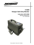
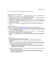
1
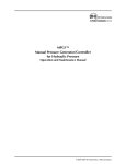
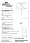
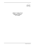
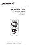
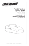
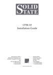
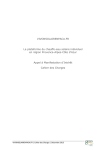
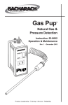
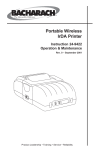
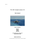
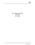
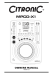
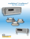
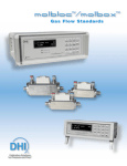
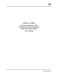
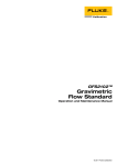
MPC1-D-1000/MPC1-D-3000
Manual Pressure Controller
for Differential Pressure
User’s Manual
©2000 DH Instruments, Inc.
MPC1-D User’s Manual
Manual Conventions
(Caution) is used in throughout the manual to identify user warnings and cautions.
(NOTE) is used throughout the manual to identify operating and applications advice and
additional explanations.
High pressure liquids and gases are potentially hazardous. Energy stored in these liquids and gases can
be released unexpectedly and with extreme force. High pressure systems should be assembled and
operated only by personnel who have been instructed in proper safety practices.
© 2000 DH Instruments, Inc. All rights reserved.
Information in this document is subject to change without notice. No part of this document may be reproduced or
transmitted in any form or by any means, electronic or mechanical, for any purpose, without the express written
permission of DH Instruments, Inc., 4765 East Beautiful Lane, Phoenix, AZ 85044-5318, USA.
DH Instruments makes sincere efforts to ensure the accuracy and quality of its’ published materials; however, no
warranty, expressed or implied, is provided. DH Instruments disclaims any responsibility or liability for any direct or
indirect damages resulting from the use of the information in this manual or products described in it. Mention of any
product or brand does not constitute an endorsement by DH Instruments of that product or brand. This manual was
originally composed in English and was subsequently translated into other languages. The fidelity of the translation
cannot be guaranteed. In case of conflict between the English version and other language versions, the English
version predominates.
DH Instruments, DH, DHI, MPC1, MPC1-D. PG7000, RPM3 are trademarks, registered and otherwise, of
DH Instruments, Inc.
Document No. 550119
000606
Printed in the USA
©2000 DH Instruments, Inc.
MPC1-D User’s Manual
TABLE OF CONTENTS
TABLE OF CONTENTS ................................................................................ i
TABLES .................................................................................................... ii
FIGURES .................................................................................................. ii
1. INTRODUCTION .................................................................................... 1
1.1
1.2
1.3
1.4
PRODUCT OVERVIEW .............................................................................................................................1
LOCATION OF THE COMPONENTS ........................................................................................................1
SPECIFICATIONS .....................................................................................................................................2
DIMENSIONAL SCHEMATICS..................................................................................................................3
2. INSTALLATION ..................................................................................... 5
2.1
2.2
2.3
UNPACKING AND INSPECTION ..............................................................................................................5
SITE REQUIREMENTS..............................................................................................................................5
INITIAL SETUP ..........................................................................................................................................5
3. OPERATION ......................................................................................... 7
3.1
GENERAL OPERATING PRINCIPLES AND INFORMATION...................................................................7
3.1.1
3.1.2
3.1.3
3.1.4
3.2
3.3
SETTING ZERO LINE PRESSURE (VENTED) .........................................................................................9
SETTING A LINE PRESSURE ..................................................................................................................9
3.3.1
3.3.2
3.4
3.5
OVERVIEW ........................................................................................................................................................7
VALVES .............................................................................................................................................................7
VARIABLE VOLUME (VV) .................................................................................................................................8
PRESSURE GAUGE ..........................................................................................................................................9
INCREASING LINE PRESSURE .....................................................................................................................10
DECREASING LINE PRESSURE ....................................................................................................................10
SETTING DIFFERENTIAL PRESSURES AT LINE PRESSURES ..........................................................11
SETTING SINGLE CHANNEL PRESSURES ..........................................................................................12
3.5.1
3.5.2
INCREASING PRESSURE ..............................................................................................................................12
DECREASING PRESSURE .............................................................................................................................13
4. MAINTENANCE AND ADJUSTMENTS ................................................... 15
5. TROUBLESHOOTING .......................................................................... 17
5.1
5.2
5.3
GENERAL INFORMATION......................................................................................................................17
LEAKS .....................................................................................................................................................17
TEST PRESSURE WILL NOT CHANGE.................................................................................................18
5.3.1
5.3.2
5.3.3
5.4
TEST INLET VALVE ........................................................................................................................................18
VARIABLE VOLUME (VV) ...............................................................................................................................18
VENT VALVE ...................................................................................................................................................19
PRESSURE CHANGES SLOWLY OR SLUGGISHLY ............................................................................19
6. ANNEXES ........................................................................................... 21
6.1
6.2
PNEUMATIC SCHEMATIC ......................................................................................................................21
VARIABLE VOLUME INFORMATION.....................................................................................................22
6.2.1
6.3
VARIABLE VOLUME SPECIFICATIONS ........................................................................................................23
WARRANTY STATEMENT ......................................................................................................................23
Page i
©2000 DH Instruments, Inc.
MPC1-D User’s Manual
TABLES
Table 1.
Table 2.
Variable Volume Specifications............................................................................................... 23
DHI Authorized Service Providers........................................................................................... 24
FIGURES
Figure 1.
Figure 2.
Figure 3.
Figure 4.
Figure 5.
Figure 6.
Front Panel ................................................................................................................................ 1
Rear Panel................................................................................................................................. 2
Side View with Dimensions ....................................................................................................... 3
Top View with Dimensions ........................................................................................................ 3
System Schematic................................................................................................................... 21
Variable Volume Schematic .................................................................................................... 22
©2000 DH Instruments, Inc.
Page ii
MPC1-D User’s Manual
1. I NTRODUCTION
1.1 PRODUCT OVERVIEW
The DHI Manual Pressure Controller for Differential Pressure (MPC1-D) provides a compact and
easy to use system for manually setting and adjusting pressures between atmosphere and 1 000 or
3 000 psi in systems where precise pressure control is required. MPC1-D is a dual configuration
designed specifically for use in setting and adjusting differential pressures at elevated line pressure.
It is the standard pressure control component for working with DHI’s PG7102 piston gauges in High
Line Differential Pressure mode. A single channel model, MPC1, is available for applications other
than differential pressures at elevated static pressures.
MPC1-D-1000 is for pressures to 1 000 psi (7 MPa), MPC1-D-3000 is for pressures to 3 000 psi
(21 MPa).
1.2 LOCATION OF THE COMPONENTS
L O / H I B Y PA S S
C LO S ED
O P EN
LO
E Q U A L IZ E
PU S H
TO
C LO S E
1.
2.
3.
4.
P U LL
TO
O PEN
Variable Volume Equalization Valve (lo side)
Variable Volume (lo side)
Lo Side/Hi Side Bypass Valve
Pressure Gauge (1 000 or 3 000 psi)
5.
6.
7.
8.
Vent Valve
Variable Volume Equalization Valve (hi side)
Inlet Valve
Variable Volume (hi side)
Figure 1. Front Panel
Page 1
©2000 DH Instruments, Inc.
MPC1-D User’s Manual
REF HI
TE S T H I
T ES T LO
S U P P LY
R E F LO
V EN T
1
6
1.
2.
3.
Gas Supply Connection (1/8 in. NPT)
Ref Hi Connection (1/8 in. NPT)
Test Hi Connection (1/8 in. NPT)
4.
5.
6.
Test Lo Connection (1/8 in. NPT)
Ref Lo Connection (1/8 in. NPT)
Vent Connection (1/8 in. NPT)
Figure 2. Rear Panel
1.3 SPECIFICATIONS
Pressure Range:
Pressure Supply:
Pressure Connections:
Dimensions:
Weight:
MPC1-D-1000: Atmosphere to 1 000 psi (7 MPa)
MPC1-D-3000: Atmosphere to 3 000 psi (21 MPa)
Equal to or greater than the maximum pressure desired
MPC1-D-1000: 1 200 psi (8 MPa) (maximum supply)
MPC1-D-3000: 3 200 psi (22 MPa) (maximum supply)
1/8 in. NPT Female (Supply, Vent, Test Hi, Test Lo, Ref Hi, Ref
Lo)
320 mm x 128 mm x 370 mm (WxHxD)
(12.6 in. x 5.0 in. x 14.6 in.) (see Section 1.4)
9.1 kg (20 lbs.)
Due to a policy of continual product improvement all specifications are subject to change
without notice.
©2000 DH Instruments, Inc.
Page 2
MPC1-D User’s Manual
1.4 DIMENSIONAL SCHEMATICS
All dimensions are in millimeters.
172
369
300
Figure 3. Side View with Dimensions
320
Figure 4. Top View with Dimensions
Page 3
©2000 DH Instruments, Inc.
MPC1-D User’s Manual
NOTES
©2000 DH Instruments, Inc
Page 4
.
MPC1-D User’s Manual
2. I NSTALLATION
2.1 UNPACKING AND INSPECTION
The MPC1-D is delivered with the inlet valve closed, exhaust valve open and the variable volume
(VV) fully screwed in. Cap plugs cover all rear panel pressure connections.
2.2 SITE REQUIREMENTS
•
Gas supply up to maximum amount for model used.
2.3 INITIAL SETUP
If a DHI PK-7100-MPCD-DIF connections kit P/N 401645 was purchased with the MPC1-D, use it to
make the MPC1-D connections. Refer to the kit’s instruction sheet.
All MPC1-D pressure connections are 1/8 in. NPT female. Therefore, a 1/8 in. NPT male adaptor is
needed to make each of the connections. NPT connections should be sealed using an appropriate
sealing tape on the threads.
Connect the SUPPLY port to a suitable source of clean, dry, non-corrosive gas.
Connect the REF HI and REF LO ports to the hi and lo reference devices. These are the Tare and
Reference PG7102s if setting up a PG7102 High Line Differential Pressure calibration system.
The Tare PG7102 is REF LO, the reference PG7102 is REF HI.
Connect the TEST HI and TEST LO ports to the device under test hi and lo sides.
The VENT port may be connected to direct vented gases if desired, but a connection is not required.
Do not plug or shut off the VENT port.
Page 5
©2000 DH Instruments, Inc.
MPC1-D User’s Manual
NOTES
©2000 DH Instruments, Inc
Page 6
MPC1-D User’s Manual
3. O PERATION
3.1 GENERAL OPERATING PRINCIPLES AND INFORMATION
3.1.1
OVERVIEW
See Section 6.1, Figure 5.
This instrument manually controls line pressure and differential pressures from atmosphere
to 1 000 psi (7 MPa) (MPC1-D-1000) or atmosphere to 3 000 psi (21 MPa) (MPC1-D-3000)
through the use of valves, two variable volume (VV) pumps, a bypass valve and a
pressure gauge. Fittings for an outside source of pressure, connections to hi and lo
reference and test devices and a vent port are located on the rear panel.
The bypass valve is used to connect the hi and lo sides together when setting elevated static
pressures and to isolate one side from the other when setting differential pressures.
The test inlet valve is plumbed directly to the reference and test connection(s) and the high
pressure chamber of the VVs. Opening this valve, regardless of the position of the bypass
valve, will result in an increase of pressure in the test system when pressure is applied to
the valve. ESPECIALLY IF THE BYPASS VALVE IS CLOSED, THIS MAY RESULT IN AN OVER
PRESSURE CONDITION OF THE TEST INSTRUMENT. PLEASE USE CAUTION WHEN
OPERATING THE TEST INLET VALVE. ALWAYS CHECK THE BYPASS VALVE SETTING TO AVOID
ACCIDENTALLY SETTING DIFFERENTIAL PRESSURE MUCH HIGHER THAN DESIRED.
3.1.2
VALVES
Two types of valves (needle and ball) are used in the MPC1-D. Two needle valves are used
to control large changes between pressures. A ball valve acts as the bypass valve that
isolates the hi and lo sides of the system.
Operating the SUPPLY or VENT valve may change the system pressure quickly by an amount
that is largely relative to the differential pressure range in which you are working. Operate the
SUPPLY and/or VENT valve very carefully when the BYPASS valve is closed. Be sure to open
the BYPASS valve before using the SUPPLY or VENT valve to adjust the line pressure.
Page 7
©2000 DH Instruments, Inc.
MPC1-D User’s Manual
3.1.3
VARIABLE VOLUME (VV)
There are separate variable volumes on the hi and lo sides of MPC1-D.
The variable volume (VV) is a cylinder whose volume distribution is adjusted by rotating a
knob that moves an internal piston (see Section 6.2, Figure 6). Attached to the top of the VV
is a push/pull equalization valve that is designed to isolate the low side from the high side of
the piston as well as provide protection to the unit itself in certain situations.
The VV is used to adjust the pressure (and/or piston position when used with a piston gauge)
by rotating the knob to change the TEST side volume with the equalization valve closed.
Before operating the INLET or VENT valve, always open the equalization valve to avoid
causing excessive differential pressure across the VV piston. To open the equalization valve,
pull it outward; to close, push it inward.
When using the VV, it is useful to put its piston in the optimum position based on the intent
of use. Under most operating conditions, the piston is placed in its mid-stroke position
(about 16 rotations of the knob from either stop for MPC1-D-1000, 30 rotations for
MPC1-D-3000). This will allow for equal movement, forward and backward, of the piston.
When a maximum increase or decrease of pressure is required, especially at low pressures,
place the VV knob at the stop limit (either clockwise for maximum decrease in pressure or
counter-clockwise for maximum pressure increase).
The VV is designed to operate with a maximum differential pressure of 150 psi (1 MPa)
across the piston (TEST or “front” side vs. KNOB or “back” side). When the differential
pressure across the piston exceeds 150 psi (1 MPa) positive on the TEST side, the
equalization valve will automatically open reducing the differential pressure to zero. This is a
safety feature intended to prevent damage to the VV. The value of 150 psi (1 MPa) is factory
set and cannot be changed. The variable volume is not protected internally against
differential overpressure positive on the back (KNOB) side of the piston. Never vent pressure
externally of the MPC1-D or operate the VENT valve without opening the VV equalization
valves (see Section 6.2, Figure 6).
The maximum differential pressure across the variable volume (VV) equalization valve is 150
psi (1 MPa). Never vent the system externally or operate the VENT valve with a variable volume
equalization valve closed. Damage to the variable volume could result.
©2000 DH Instruments, Inc.
Page 8
MPC1-D User’s Manual
3.1.4
PRESSURE GAUGE
There is a zero to 1 000 psi (7 MPa) or zero to 3 000 psi (21 MPa) dial gauge connected to
the hi side test pressure circuit. The gauge has a dual function:
•
As a safety device since it is important for the operator to know the value of system
pressure at all times.
•
As a means to assist the operator in setting pressure.
The pressure gauge is connected to the hi side of the MPC1-D. It indicates the pressure
throughout the system when the bypass valve is open. It indicates only the hi side pressure
when the bypass valve is closed.
3.2 SETTING ZERO LINE PRESSURE (VENTED)
This procedure applies when using MPC1-D on both channels to set differential pressures at
elevated static pressures.
n Close the SUPPLY valve.
o Open both hi and lo VV pressure equalization valves (pull knob outward).
OPENING AN EQUALIZATION VALVE MAY RESULT IN A SUDDEN CHANGE IN THE TEST PRESSURE.
Ensure conditions are such that this either does not happen or that its effects are inconsequential.
p Open the HI/LO BYPASS valve.
q Open the VENT valve.
3.3 SETTING A LINE PRESSURE
This procedure applies when using MPC1-D on both channels to set differential pressures at
elevated static pressures.
All procedures instruct the operator to open the equalization valve prior to opening the SUPPLY valves.
THIS IS A SAFETY PRECAUTION. It is possible to adjust the pressure in the test circuit using the
SUPPLY or VENT valve without opening the variable volume equalization valve. However, this should be
done ONLY WHEN THE OPERATION OF THE SYSTEM AND THE NECESSARY PRECAUTIONS ARE
UNDERSTOOD BY THE OPERATOR. Refer to Sections 3.1, 6.1 and 6.2 for more information.
Page 9
©2000 DH Instruments, Inc.
MPC1-D User’s Manual
3.3.1
INCREASING LINE PRESSURE
n Open the HI/LO BYPASS valve.
o Open both variable volume equalization valves (pull knob outward).
OPENING AN EQUALIZATION VALVE MAY RESULT IN A SUDDEN CHANGE IN THE
TEST PRESSURE. Ensure conditions are such that this either does not happen or that its
effects are inconsequential.
p Carefully operate the SUPPLY valve to admit pressure until the approximate desired line
pressure is reached.
q Place lo VV piston at appropriate position (see Section 3.1.3) and close its equalization
valve (push knob inward).
r Adjust VV knob until desired line pressure is obtained (or until the piston floats when
connected to a piston gauge).
Maximum differential pressure across the VV piston is 150 psi (1 MPa). Differential pressures
above 150 psi (1 MPa) on the TEST side will automatically open the equalization valve.
s To set a differential pressure after setting a line pressure, see Section 3.4.
t To set another, higher, line pressure, repeat Step n or s above. To set a lower line
pressure, see Section 3.3.2.
3.3.2
DECREASING LINE PRESSURE
n Open the HI/LO BYPASS valve.
o Open both variable volume equalization valves (pull knob outward).
OPENING AN EQUALIZATION VALVE MAY RESULT IN A SUDDEN CHANGE IN THE
TEST PRESSURE. Ensure conditions are such that this either does not happen or that its
effects are inconsequential.
p Carefully operate the VENT valve to exhaust pressure until the approximate desired
pressure is reached.
q Place lo VV piston at appropriate position (see Section 3.1.3) and close its equalization
valve (push knob inward).
©2000 DH Instruments, Inc.
Page 10
MPC1-D User’s Manual
r Adjust VV knob until desired line pressure is obtained (or until the piston floats when
connected to a piston gauge).
Maximum differential pressure across the VV piston is 150 psi (1 MPa). Pressures above
150 psi (1 MPa) will automatically open the equalization valve.
s To set a differential pressures after setting a line pressure, see Section 3.4.
t To set another, lower, line pressure, repeat Step n or s above. To set a higher line
pressure, see Section 3.3.1.
3.4 SETTING DIFFERENTIAL PRESSURES AT LINE
PRESSURES
For instructions on setting line pressure, see Section 3.3. Once the line pressure has been set,
follow the instructions below to set differential pressures.
n Close HI/LO BYPASS valve.
CLOSING THE HI/LO BYPASS VALVE ISOLATES ONE SIDE OF THE DEVICE UNDER TEST (DUT)
FROM THE OTHER. When the BYPASS valve is closed, Take care to avoid accidentally setting
larger differential pressure than desired. Exercise special care if it is necessary to operate
the SUPPLY or VENT valve as these can cause large pressure changes to occur quickly.
o Place hi VV piston at appropriate position (see Section 3.1.3) and close its equalization valve
(push knob inward).
p Adjust hi VV knob until desired differential pressure is obtained (or until the piston floats when
connected to a piston gauge). If desired, the lo VV knob may also be adjusted, for example
to maintain a piston gauge piston in float position and/or to maintain the line pressure.
Maximum differential pressure across the VV piston is 150 psi (1 MPa). Pressures above
150 psi (1 MPa) will automatically open the equalization valve.
Page 11
©2000 DH Instruments, Inc.
MPC1-D User’s Manual
q If the hi VV reaches end of stroke before the desired differential pressure is set, open the
VV’s equalization valve and adjust it to an appropriate start position, then use the SUPPLY or
VENT valve to admit or exhaust pressure. Be sure to open the hi VV equalization valve
before operating the SUPPLY or VENT valve. Then close the equalization valve and resume
use of the VV.
If the lo VV reaches end of stroke before the desired differential pressure is set, try opening
the VV’s equalization valve, adjusting it to a suitable start position and using it again. If this
does not achieve the desired result, the only solution is to open the HI/LO BYPASS valve to
admit or exhaust pressure using the SUPPLY or VENT valve. This will cause the differential
pressure to go to zero. Be sure to open both VV equalization valves before operating the
SUPPLY or VENT valve.
OPERATING THE SUPPLY OR VENT VALVE MAY RESULT IN A SUDDEN CHANGE IN THE
TEST PRESSURE. Ensure conditions are such that this either does not happen or that its
effects are inconsequential.
r Repeat Steps p and q for additional differential pressure increments, as desired.
3.5
SETTING SINGLE CHANNEL PRESSURES
To use the MPC1-D on a single channel use the hi side. Connect to the HI TEST port (and HI REF
port if needed). Close the HI/LO BYPASS valve. Then use the SUPPLY and VENT valves and the hi
VV as if setting line pressures.
3.5.1
INCREASING PRESSURE
n Close HI/LO bypass valve.
o Close VENT valve.
For small pressure changes, it may be possible to reach the desired pressure using the VV
only, proceed to Step s below.
p Open hi VV pressure equalization valve (pull knob outward).
OPENING THE EQUALIZATION VALVE MAY RESULT IN A SUDDEN CHANGE IN THE
TEST PRESSURE. Ensure conditions are such that this either does not happen or that
its effects are inconsequential.
q Place hi VV piston at appropriate position (see Section 3.1.3).
©2000 DH Instruments, Inc.
Page 12
MPC1-D User’s Manual
r Open SUPPLY valve until the approximate desired pressure is reached. Care should be
taken not to overrange the test.
s Close hi VV equalization valve (push knob inward).
t Adjust hi VV knob until desired pressure is obtained (or until the piston floats when
connected to a piston gauge).
Maximum differential pressure across the VV piston is 150 psi (1 MPa). Pressures above
150 psi (1 MPa) will automatically open the equalization valve
u To continue increasing pressures, repeat Steps p through t above.
3.5.2
DECREASING PRESSURE
For small pressure changes, it may be possible to reach the desired pressure using the VV
only, proceed to Step r below.
n Open hi VV pressure equalization valve(pull knob outward).
OPENING THE EQUALIZATION VALVE MAY RESULT IN A SUDDEN CHANGE IN THE
TEST PRESSURE. Ensure conditions are such that this either does not happen or that
its effects are inconsequential.
o Place hi VV piston at appropriate position (see Section 3.1.3).
p Open VENT valve until the approximate desired pressure is reached.
q Close hi VV equalization valve (push knob inward).
r Adjust VV knob until desired pressure is obtained (or until the piston floats when
connected to a piston gauge).
s To continue decreasing pressures, repeat Steps n through r above.
Page 13
©2000 DH Instruments, Inc.
MPC1-D User’s Manual
NOTES
©2000 DH Instruments, Inc.
Page 14
MPC1-D User’s Manual
4. M AINTENANCE A ND
A DJUSTMENTS
MPC1-D requires no routine maintenance or adjustments.
Page 15
©2000 DH Instruments, Inc
MPC1-D User’s Manual
NOTES
©2000 DH Instruments, Inc
Page 16
MPC1-D User’s Manual
5. T ROUBLESHOOTING
5.1 GENERAL INFORMATION
The MPC1-D consists of three valves, two variable volumes (VV), a pressure gauge and various
tubing and fittings. Several predictable failures can occur while using the instrument and are
addressed in this section. It is recommended that whomever performs the following troubleshooting
procedures become familiar with the system schematic (see Section 6.1) including the VV description
(see Section 6.2).
For failures not covered in this section, or direct technical assistance and/or for ordering information
on replacement components, please contact DH Instruments, Inc. or your local DHI representative.
Because of the close fitting components and short tubing runs, some users may find it preferable to
return the MPC1 to a DHI Authorized Service Provider for repair rather than perform the
troubleshooting and repair themselves. For repair services, contact a DHI Authorized Service
Provider (see Section 6.3).
5.2 LEAKS
Pressure leaks are the most common problem found in pressure handling equipment. Normally, the
first step is to determine if the leak is within the MPC1-D or if it is outside of the unit.
To determine if the leak is within the MPC1-D, you must disconnect the unit at the test and reference
connections and plug them. Establish similar conditions under which the leak was observed and
determine if the leak is still present. For small leaks, it may be necessary to install an appropriate
pressure sensing device at a test port, user discretion required. In some cases, it is useful to
perform simple leak checks on the most common outside sources before disconnecting the
test system.
Leaks inside the MPC1 are unusual unless there has been some disassembly.
More than one leak can exist in a system so fixing one does not guarantee a leak tight system.
Therefore, continue executing troubleshooting procedures until all leaks are located and corrected.
Page 17
©2000 DH Instruments, Inc
MPC1-D User’s Manual
5.3 TEST PRESSURE WILL NOT CHANGE
There are five components involved in changing the pressure:
•
SUPPLY valve.
•
Variable Volumes (2).
•
VENT valve.
•
HI/LO BYPASS valve.
The MPC1 uses very small inside diameter control tubes. The purpose of the filters is to protect these
tubes and the valves from contamination. Do NOT operate the MPC1 without an active filter element
of 0.5 micron rating.
5.3.1
TEST INLET VALVE
Two situations can cause a failure to change pressure when using the test inlet valve:
1. A problem with the supply pressure.
2. A plugged filter.
Check the supply and ensure that a gas supply is actually present at the supply port and the
supply pressure is adequate to achieve maximum pressure needs. If the supply is OK, check
the filter by removing the top cover and then removing the filter from the supply line. If the
filter is plugged, disassemble and clean or replace the filter.
5.3.2
VARIABLE VOLUME (VV)
While using the VV to generate pressures it may appear that under certain conditions it is not
working when in fact it is. For example, when the system is at low pressure (typically below
5 psig) and working into a large volume. This is due to the compressibility of gases at low
pressures which worsens as pressures decrease and volumes increase. Consider this
situation when evaluating the performance of the VV.
If pressure cannot be changed through the use of the VV, the problem is with the equalization
valve, the VV piston O-ring or the filter connected to the VV rear plate. Confirm that the
equalization valve is closed (pushed in).
The VV cannot change the pressure when the equalization valve is open. If pressures still
cannot be changed, remove the top panel and the filter. Check the filter for a plugged
condition, clean or replace as needed. If the VV still cannot change the test pressure, have
it serviced.
©2000 DH Instruments, Inc.
Page 18
MPC1-D User’s Manual
5.3.3
VENT VALVE
Three problems can cause the failure of the VENT valve to change pressures:
•
An incorrectly positioned outlet selection valve.
•
A closed equalization valve.
•
A plugged filter.
Ensure the outlet selection valve is in the proper position for the work being done (either
VENT or VACUUM). If the valve is in the OFF position, select VENT or VACUUM.
Ensure the equalization valve is open (pull out). If the valve was closed, be aware that a
sudden change of pressure at the test can occur when the valve is opened.
Check if the filter is plugged.
5.4 PRESSURE CHANGES SLOWLY OR SLUGGISHLY
This is caused by a partially plugged filter or a large connected volume. Remove and clean or
replace the filter as needed.
The MPC1-D uses very small inside diameter control tubes. The purpose of the filters is to protect
these tubes and the valves from contamination. Do NOT operate the MPC1 without the active filter
elements of less than a 0.5 micron rating.
Pressure changes can be slow if a large external volume is connected to a MPC1-D. This condition
is compounded by a low supply pressure. If the pressure changes are too slow due to a large
external volume, reduce the volume.
Page 19
©2000 DH Instruments, Inc.
MPC1-D User’s Manual
NOTES
©2000 DH Instruments, Inc
Page 20
MPC1-D User’s Manual
6. A NNEXES
6.1 PNEUMATIC SCHEMATIC
1.
2.
3.
4.
5.
6.
7.
8.
Variable volume (lo side)
Variable volume equalization valve (lo side)
Check valve
Filter
Lo ref connection (1/8 in. NPT)
Lo test connection (1/8 in. NPT)
Hi test connection (1/8 in. NPT)
Hi ref connection (1/8 in. NPT)
9.
10.
11.
12.
13.
14.
15.
16.
Vent connection (1/8 in. NPT)
Gas supply connection (1/8 in. NPT)
Inlet valve
Variable volume (hi side)
Variable volume equalization valve (hi side)
Vent valve
Gauge (1 000 or 3 000 psi)
Lo side/Hi side bypass valve
Figure 5. System Schematic
Page 21
©2000 DH Instruments, Inc.
MPC1-D User’s Manual
6.2 VARIABLE VOLUME INFORMATION
VENT VALVE
INLET VALVE
EQUALIZATION VALVE
CLOSED
SYSTEM IN TEST MODE
(EQUALIZATION VALVE CLOSED)
TEST
SIDE
PISTON
VENT
INLET
EQUALIZATION VALVE
OPEN
TEST
SIDE
PISTON
Figure 6. Variable Volume Schematic
©2000 DH Instruments, Inc.
Page 22
SYSTEM IN PRESSURE
EQUALIZATION OR VENT MODE
(EQUALIZATION VALVE OPEN)
MPC1-D User’s Manual
6.2.1
VARIABLE VOLUME SPECIFICATIONS
Table 1. Variable Volume Specifications
Range
Proof
Burst
Approx. Total Volume Change
Mechanical Rotation
Operating Temperature Range
MPC1-1000
Vacuum to 1 000 psi
3 000 psi
6 000 psi min
3.5 cu in.
31
20 to 120 °F
MPC1-3000
Vacuum to 3 000 psi
6 000 psi
12 000 psi min
2.5 cu in.
61
20 to 120 °F
6.3 WARRANTY STATEMENT
Except to the extent limited or otherwise provided herein, DH Instruments, Inc. (DHI) warrants for
one year from purchase, each new product sold by it or one of its authorized distributors, only against
defects in workmanship and/or materials under normal service and use. Products which have been
changed or altered in any manner from their original design, or which are improperly or defectively
installed, serviced or used are not covered by this warranty.
DHI and any of its Authorized Service Providers’ obligations with respect to this warranty are limited
to the repair or replacement of defective products after their inspection and verification of such
defects. All products to be considered for repair or replacement are to be returned to DHI, or its
Authorized Service Provider, freight prepaid, after receiving authorization from DHI or its Authorized
Service Provider. The buyer assumes all liability vis-à-vis third parties in respect of its acts or
omissions involving use of the products. In no event shall DHI be liable to purchaser for any
unforeseeable or indirect damage, it being expressly stated that, for the purpose of this warranty,
such indirect damage includes, but is not limited to, loss of production, profits, revenue, or goodwill,
even if DHI has been advised of the possibility thereof, and regardless of whether such products are
used individually or as components in other products.
Items returned to DHI under warranty claim but determined to not have a defect covered under
warranty or to not have a defect at all are subject to an evaluation and shipping charge as well as
applicable repair and/or calibration costs.
The provisions of this warranty and limitation may not be modified in any respect except in writing
signed by a duly authorized officer of DHI.
The above warranty and the obligations and liability of DHI and its authorized service providers
exclude any other warranties or liabilities of any kind.
Page 23
©2000 DH Instruments, Inc.
MPC1-D User’s Manual
Table 2. DHI Authorized Service Providers
DH INSTRUMENTS, INC.
www.dhinstruments.com
AUTHORIZED SERVICE PROVIDERS
COMPANY
TELEPHONE
& FAX
ADDRESS
EMAIL
DH Instruments, Inc.
4765 East Beautiful Lane
Phoenix, AZ 85044-5318
USA
Tel 602.431.9100
Fax 602.431.9559
[email protected]
Nippon CalService, Inc.
2-9-1 Sengen, Tsukuba-Shi
Ibaraki Prefecture 305
JAPAN
Tel 0298-55-8778
Fax 0298-55-8700
[email protected]
DHI Products Technical
Service Division
National Institute of Metrology
Heat Division
Pressure & Vacuum Lab
NO. 18, Bei San Huan Donglu
Beijing 100013
PR China
Tel 010-64291994 ext 5
Tel 010-64218637 ext 5
Fax 010-64218703
[email protected]
Minerva Meettechniek B.V
Chrysantstraat 1
3812 WX Amersfoort
the NETHERLANDS
Tel (+31) 33.46.22.000
Fax (+31) 33.46.22.218
[email protected]
©2000 DH Instruments, Inc.
Page 24