1
Laub
33
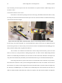
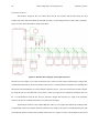
be written to one at a time. Data is written to one address and then the next data point is written to the incremented
address and so on. This creates one column of mixed data points; however, because the method of writing data is
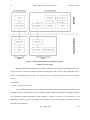
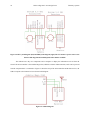
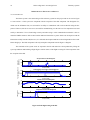
known then the pattern of the data can be separated out during analysis. Figure 17 illustrates this two column
explanation and how the order of data can be predicted.
Figure 17: Example of stored EEPROM data points from The Yorktown system.
Since the pattern of the information in the column is known, it can be extracted easily using a MATLAB script
developed for the project, Appendix L.
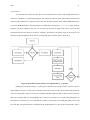
After the information has been saved the altitude information is then transmitted to the ground station. Then
the loop checks the push button and if it has been pressed it enters standby mode, else it continues looping. When
the system enters standby mode the next ten addresses on the EEPROM space have the value 255 written to them.
When reading the memory, the read function knows where to stop when reading all of the data because ten 255 data
points in a succession indicates a stop. It would be inefficient to read all of the 32,768 addresses onboard the chip if
large amounts haven’t been used. This minimizes the time that the user has to wait while the data is read from the
EEPROM chip.