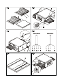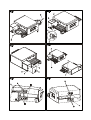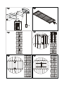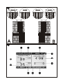
1
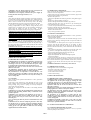
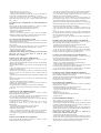
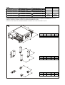
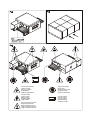
Cod.73341170
Ver.:A5
Denominazione Denomination
Bezeichnung Denominación
T75E
T97E
FORNO A TUNNEL
CONVEYOR OVEN
FOUR TUNNEL
TUNNELOFEN
HORNO DE TÚNEL
MOD.
MATR.
We declare under sole responsability that the products to which this declaration
relates is in conformity with the following standards <> following the provisions
of the directives<>.
INDEX
01 TECHNICAL DATA
2
02 INSTALLATION
2
03 OPERATION
3
04 ORDINARY MAINTENANCE
5
05 SPECIAL MAINTENANCE
6
06 NOISE LEVELS
8
07 LIST OF SPARE PARTS
8
Note:
This catalogue is printed in five different languages, and namely: Italian, English, French, German and Spanish.
WARRANTY
Standards and rules
Warranty only covers the replacement free to factory of pieces eventually broken or damaged because of faulty materials or manufacture.
Warranty does not cover any damages caused by third party transport or due to incorrect installation or maintenance, to
carelessness or negligence in usage, or to tampering by a third party. Moreover, warranty does not cover: glass components,
electrical components, accessories and whatever depends on normal wear and deterioration of both the system and its accessories;
nor does it cover labour costs involved in replacing pieces covered by warranty
Warranty ends in case of non-compliance with payments and for any elements that may be repaired, modified or disassembled, even in part,
without prior written consent. For technical service during the warranty period, please send a written request to the local concessionary agent
or directly to the Sales Department.
WARNING
This word indicates a danger, and will be employed every tiem the safety of the operator might be involved.
NOTE
This word indicates the need for caution, and will be employed to call attention to operations of primary importance for correct and longterm operation of the appliance.
DEAR CUSTOMER
Before using the appliance, please read this user manual.
For the safety of the operator, the appliance safety evices should always be maintaned in a proper state of efficiency.
This user manual intends to illustrate use and maintenance of the appliance. For this reason, the operator is advised to follow the instructions
given below.
The manufacturer reserves the right to make improvements to the product and manual, without necessarily updating existing products and
manuals.
WARNING!
1 The following instructions are provided for your safety
2 Please read them carefully before installing and using the appliance.
3 Keep this user manual in a safe place for future consultation by the operators.
4 Installation must be carried out in accordance with the Manufacturer’s instructions by qualified and licensed staff.
5 This appliance must only be employed for the purposes for which it was designed, that is to say to cook pizza and similar food
products. Any other use can be classed as improper.
6 The appliance must only be used by persons trained to operate it.
7 When carrying out repairs, always contact one of the Manufacturer’s authorised service centres and request that original spare
parts be used.
8 Failure to comply with the above may compromise the safety of the appliance.
9 In the event of breakdown or malfunction always disconnect the appliance, and do not attempt to make adjustments or repairs
yourself.
10 Should the appliance be sold or transferred to another owner, or should the current owner change his premises and wish to install
the appliance elsewhere, always ensure that this manual remains with the appliance, so that it can be consulted by the new owner
and/or the person carrying out installation.
UK/1
1 TECHNICAL SPECIFICATIONS
2.3 ENVIRONMENTAL SPECIFICATIONS
To ensure that the oven operates properly, it is advisable to comply
with the following limits:
Working temperature: +5°C ÷ +40°C
Relative humidity: 15% ÷ 95%
1.1 DESCRIPTION OF THE APPLIANCE
The oven comprises a baking chamber through which runs a
conveyor belt carrying the product, which is cooked by a jet of air
heated by electrical heating elements; it is fitted with electronic
temperature regulation at the top and bottom, a safety thermostat, and
a bottom-hinged door.
The internal and external structure is in stainless steel plate, while the
mesh conveyor belt carrying the product to be cooked is made of
stainless steel.
Up to three baking chambers can be positioned one on top of the
other, and each one is fully independent.
The baking chamber/s is/are sustained by four steel supports
mounted on wheels.
2.4 POSITIONING, ASSEMBLING AND MAINTENANCE
AREAS
WARNING! When positioning, assembling and installing the
oven, the following specifications have to be complied with:
- Laws and standards in force regarding the installation of
electrical appliances.
- Directives and indications issued by the electricity supply
network.
- Local building and fire-prevention laws.
- Accident prevention regulations.
- Indications in force issued by local state Electric Quality
Assurance Corporation.
After unloading, the appliance must be positioned in a well-aired and
illuminated room, with adequate ducting, at a minimum distance of
10cm from the right side wall and from the rear wall and 80 cm from
the left side wall (fig.6).
These minimum distances are essential to guarantee access to the
main switch and to guarantee ducting of cooling air at the back.
WARNING! Air is sucked through the central perforated part of
the rear casing (fig.11) and this must never be obstructed, take
care not to insert thin tools, hair, clothing etc. through the holes
so that they come into contact with the fan.
The following operations must be carried out:
- Remove the protective film from the outer panels of the oven,
pulling it gently to remove all the adhesive.
Should any adhesive remain on the oven, remove using kerosene or
benzene.
- After removing the four round headed screws (fig.7 item A) on the
bottom of the appliance, fit the four supports, each one fastened with
four screws and washers (fig.7 item B), in the threaded holes
provided on the base; once the appliance has been moved into
position lock it by pressing the brake lever (fig.7 item C) on each of
the wheels down.
Any support that is not supplied by the manufacturer must be suitable
to guarantee proper stability of the oven.
- The single elements that have been selected to make up the oven
must be placed one on top of the other as shown in figure 8, after
removing the 4 plastic plugs (fig.8 item D) from the top part of the
element to be positioned underneath and inserting the round headed
reference screws (item 8 fig.E) into the element to be positioned on
top.
- Connect up any optional product rest (fig.9) on the side required,
after removing the stop (fig.9 item F) and relative knobs (fig.9 item
G) from the flour collector and replacing them on the product rest
itself.
WARNING! The lock (fig.10 item H) on the front door must
always be fitted and the keys must be removed and kept by staff
authorised to work the appliance, in order to avoid accidental
opening of the front door with a resulting severe risk of burning
and injury by internal parts.
Of the various people authorised and trained to use the
appliance, at least one must always be present when the
appliance is turned on, and must be aware of the location (near
the appliance) of a set of keys, in order to allow opening of the
door in an emergency. If there are a number of baking
chambers, mark the keys and respective locks clearly so that they
can be recognised with ease
1.2 REGULATIONS APPLIED
This appliance complies with the following regulations:
- Low voltage Directive 73/23, as modified by Directive 93/68 EEC
dated 22/07/1993.
- Electromagnetic compatibility Directive 89/336, as modified by
Directives 92/31 dated 15/05/1992 and 93/68 EEC dated
22/07/1993.
- Machine Directive 89/392 EEC, as modified by Directives 91/368
EEC, 93/44 EEC and 93/68 EEC dated 22/07/1993.
1.3 WORKPLACES
The appliance is programmed by the operator using the control panel
on the front of the oven, and it must be attended to while in
operation.
The glazed door is located at the front of the oven.
1.4 ACCESSORIES
The following accessories are available:
- Product rest.
- GSM card for on-line connection
1.5 TECHNICAL DATA (See TAB.1)
1.6 DIMENSIONS AND WEIGHTS (see Fig.1)
1.7 IDENTIFICATION
When communicating with the manufacturer or service centre,
always give the oven SERIAL NUMBER, which can be found on the
plate fixed as shown in fig.2.
1.8 LABELLING
The oven is provided with warning labels at the points indicated in
fig. 4.
2 INSTALLATION
NOTE: the manufacturer declines all responsibility in the event
of failure to comply with safety regulations.
2.1 TRANSPORT AND SHIPPING
The oven is generally delivered by transport vehicle, packed in
cardboard boxes and fastened with belts to wooden pallets (fig. 3). It
must be lifted at the points indicated by the arrows.
2.2 LIFTING AND MOVEMENT
NOTE! On receiving the oven it is advisable to check its
conditions and quality.
After removing the four plastic plugs (fig. 5, item D), lift the oven by
hooking up at the points indicated in fig. 5, using a normal lifting
device (bridge crane, crane, fork lift etc.)
WARNING! The oven must not be transported manually.
Position the appliance in a suitably hygienic, clean, dry and dust-free
area, making sure that it is stable.
Replace the four plastic plugs (fig. 5 item D) in the holes.
Packing materials must be disposed of in accordance with current
regulations.
WARNING! The belts must only be replaced by other systems
with equivalent lifting and safety factors.
2.4.1 ELECTRICAL CONNECTION
WARNING! Electrical connection must only be carried out by
specialised personnel, in compliance with current local state
Electric Quality Assurance Corporation requirements.
Before starting the connection procedure, check that the earthing
system is provided in accordance with European EN standards.
Before starting the connection procedure, check that the main
power switch for the supply to which the oven is to be connected
has been turned to the “off” position.
The rating plate contains all the information necessary for proper
connection.
UK/2
2.4.2 ELECTRICAL CONNECTION OF THE BAKING
CHAMBER
WARNING! Each baking chamber must be fitted with a main
four-pole switch with fuses or an automatic switch suitable for
the values shown on the plate, to allow the single appliances to be
disconnected from the mains.
NOTE: The device selected should be in the immediate vicinity of
the oven and within easy access.
The baking chamber is delivered with the required voltage indicated
on the rating plate (fig. 2) and is normally set up for a power supply
of: 400 Vac. 3N 50/60 Hz or 230 Vac. 3 50/60 Hz.
- Fitting the plug (fig.12).
WARNING! Make sure that the wires connected to the power
plug do not touch each other at any point.
NOTE! Check that the direction of movement is the one
indicated by the arrow on the back of the appliance (fig. 11) and
if this is not the case change the position of one of the wires in the
power plug.
WARNING! Make sure that the belt turns in the direction
indicated in fig.27 (A=standard – B=on request), the hookshaped ends must never move in a direction that will tend to
unfasten them, because this would not only damage the belt, but
would also render them extremely dangerous and liable to hook
onto any loose clothing, limbs, rings, bracelets etc.. Follow the
procedure indicated in point 5.7.3 to change the direction of
movement
These appliances must also be included in the unipotential system.
The terminal to be used for this purpose is located at the back of the
appliance (fig.11 item W).
It is marked with the symbol
.
When connection has been completed, check that the supply voltage,
with the appliance running, does not differ from the rated value by
more than ±10%.
at which the conveyor belt turns there is a risk of being dragged
and crushed by movement of the belt itself.
- In particular, bear in mind that the glass in the front door, the
adjustable side walls and the conveyor belt heat up when the
oven is in use, and must never be touched to avoid burning; when
a number of chambers are fitted on top of each other, the upper
chambers may heat up, so you should never touch the outer walls
to avoid burning.
The three parameters to be set for cooking are: the ceiling
temperature, the floor temperature, the cooking time (time it takes the
pizza to travel through the baking chamber, which is directly
dependent on the belt speed).
It is possible to store up to 4 different cooking programs, which can
be called up and/or modified at any time.
The special functions include: the “Timer”, which allows the oven to
be turned on at different times for each day of the week, the
“Economy” or energy saving function, which can be used during
pauses in cooking, the “Lock” function, which allows a series of
operations to be protected by a password, so as to allow use of the
oven by untrained personnel.
The control unit can be set to two different languages: English or
Italian, and it can be set to display temperature in Centigrade or in
Fahrenheit. See point 5.10 on how to change the settings.
SETTING THE LANGUAGE:
to set the language, press the “left arrow” and “up arrow” keys
simultaneously, then select the language you require using the up and
down arrows;
press OK to confirm.
The control unit can be set to display temperature in Centigrade or in
Fahrenheit. See point 5.10 on how to change the setting.
3.2.1 SCREEN (fig.28)
The oven is turned on by setting the main switch (fig.14 item N) to
position “1” .
The control panel lights up and, after a few seconds, during which
the Moretti Forni device is displayed, a screen like the one illustrated
in fig. 28 appears.
1) date and time
2) ceiling set point temperature
3) working mode ( manual or program)
4) indication of the Lock function status
5) cooking time ( time the pizza takes to pass through the oven)
6) indication of the belt status
7) indication of the Economy function status
8) indication of the Timer function status
9) floor set point temperature
10) floor temperature
11) ceiling temperature
At the top left (black on white) the date and time; again at the top but
slightly further right, indication of the current working mode (manual
or program) and the lock icon indicating whether or not the Lock
function is enabled.
Immediately below two distinct areas divide the screen in half. On
the left hand side are the ceiling and floor temperature values, both
set point and actual temperature. The icon representing the ceiling
and floor heating elements is completely black when the heating
element is actually working. On the right hand side of the screen the
elements displayed will vary according to the situation, but generally
speaking they will always include the cooking time (crossing time)
and the belt icon (in three different conditions: moving, stopped,
cooking or preheating).
Below this: on the left hand side the Moretti Forni device, on the
right hand side two indications: that showing the Timer status and
that showing whether or not the “Economy” function has been
enabled.
See point 5.11 on how to adjust the screen contrast, if necessary.
3 OPERATION
3.1 PRELIMINARY CONTROL OPERATIONS
WARNING! Before commencing start-up and programming of
the oven, always check that all electrical and earthing
connections have been properly made.
Before using the oven, clean it as described in point 4.2.
WARNING! Before starting up the appliance each time, please
ensure the following:
- Particular attention must be paid to the warning signs on the
oven (fig.4), which must be undamaged and easily legible. If this
is not the case, replace them. The guards, covers, fastening
devices and flour collector must all be fitted and working
properly.
- Any damaged or missing components must be replaced and
properly fitted before the appliance is used.
- No foreign bodies must be present on the belt.
- The working area must be properly illuminated if used during
the night or if visibility is poor.
With the oven cold, adjust the following as required:
- Height of the stop at the end of the belt (fig.9 item F) using the
knobs (fig.9 item G).
- Height of the two adjustable side walls (fig.10 item I) using the
knobs (fig.10 item L). (Any adjustments made to these settings when
the oven is hot must be made using suitable accident prevention
equipment, such as suitable insulated gloves etc., and only after
turning the oven off).
NOTE! The height of the two side walls must be as low as
possible, so as to reduce dispersion of hot air into the room and
save energy.
- Air flow section of top and bottom blowers (see point 4.2.1 on how
to dismantle them), by loosening the screws (fig.13 item M) and
changing the position of the setting as required, lock the screws again
(the manufacturer setting is fully open, and before changing it you
are advised to try various temperature and time parameters on the
control panel).
3.2.2 KEYBOARD (fig.29)
The following keys are located alongside the monitor, and details of
their uses will be given later in the manual:
12) up arrow
13) down arrow
14) right arrow
15 )left arrow
16) OK button
17) Start/Stop button
18) Timer button
3.2 STARTING UP
WARNING!
- Never allow unauthorised persons to approach the oven.
- Take particular care never to touch moving parts with your
arms, hair, bracelets, rings, tools, clothing, etc. or with any parts
that might become hooked up, because in spite of the low speed
UK/3
19) Economy button
20) Lock button
21) program key P
22) program key P1
23) program key P2
24) program key P3
25) program key P4
“manual” will be displayed at the top right hand of the screen). To
store the new values, (as described above under point 3.2.6) press the
“Program” button. The monitor will display the question: Which
program do you wish to store? Select the program using keys P1 P2
P3 or P4.
3.2.8 LOCK FUNCTION:
This function can be used to block certain operations, for safety
purposes:
The following functions are disabled:
- Storing programs (if the ”Program” key is pressed nothing will
happen)
- Variation of cooking parameters during or before cooking (it is only
possible to use one of the stored programs)
- Setting the Timer
The following functions are still enabled:
- Use of one of the 4 programs
- Selection of the “Economy” function
- Enabling the “timer” ( but it is not possible to change the time)
3.2.3 STARTING THE OVEN
On start-up, after displaying the Moretti Forni device for a few
seconds, the monitor will show the page illustrated in figure 28
containing the settings for the last cooking operation carried out. The
previous cooking mode is indicated at the top right: manual or using
a pre-set program.
If you wish to start cooking, press the “Start” button (unless there is
an indication of the maximum difference allowed between ceiling
and floor, see paragraph 3.2.18 in this regard). A message will appear
on screen requesting confirmation with OK, after which the heating
elements, the belt and the fan inside the oven will start. The icon on
the monitor representing the belt will start to move, and wavy lines
indicating the oven heating phase will be displayed; this icon will
continue to be displayed until the oven reaches the required set point
temperature.
NOTE! The floor and ceiling temperatures are constrained to
each other within a range of 20° to guarantee that the cooking
temperature is reached. It is possible to remove this constraint at
the operator’s discretion, but outside a range of 20° it is no
longer possible to guarantee that the set temperatures will be
reached (see point 3.2.18).
3.2.9 ENABLING THE “LOCK” FUNCTION:
In order to enable or disable the “Lock” function, press the relative
button.
As soon as it is pressed, a message will be displayed requesting the
password in order to enable or disable the timer (when the control
unit is first delivered the password set is: 1 1 1 1 )
3.2.10 RECORDING A PASSWORD
To record a new password, press and hold the “Lock” button: the old
password will be requested ( four asterisks indicate the number of
figures to be typed, the figures are the ones available on the keyboard
1,2,3,4, )
3.2.4
SETTING
AND
MODIFYING
COOKING
PARAMETERS:
This function can only be accessed provided the Lock has not been
enabled !!
If you do not wish to start the oven, but want to change the settings
for one of the three parameters (ceiling temperature, floor
temperature, cooking temperature), use the arrow keys. Each time
the right arrow or left arrow key is pressed, one of the three values
will be selected (highlighted in bold).
Once the value required has been selected, use the up and down
arrow keys to change the value.
NOTE! The above operation can also be carried out during
cooking, and in both cases if modifications are made to one of the
values from a generic program, the oven will automatically
“quit” that program and revert to “manual” mode.
- Maximum set point temperature allowed
360 °C.
- Minimum cooking time
2 minutes.
- Maximum cooking time
20 minutes.
The conveyor belt gear motor is fitted with a reverse rev control
which, regardless of the weight on the belt, guarantees an even transit
time
3.2.11 SETTING THE DATE AND TIME
To adjust the date and time, press the right arrow and left arrow keys
simultaneously. After pressing OK to confirm it is possible to
modify the date and time using the arrow keys (left and right arrow
to move from one field to the next, up and down arrow to change the
value). Press OK to confirm when modifications have been
completed.
3.2.12 SETTING START-UP TIMES WITH THE TIMER
This function can only be accessed provided the Lock has not been
enabled !!
It is possible to set timed start-up of the oven, entering a different
start-up time for every day of the week.
To set the start-up time, press the “Timer” button. Indications of the
days in the week will be displayed on the right of the screen, with a
time associated with each day. Using the “right arrow” key, select
the day or the time to be adjusted and then, using the “up arrow” and
“down arrow” keys, set the value required.
When the timer is enabled the oven will turn on at the first of the set
“ON” times it encounters after it has been enabled.
3.2.5 RUNNING ONE OF THE 4 PROGRAMS
If, when the oven is turned on, it is set to “manual” or to a different
program from the one required, simply press the key corresponding
to the program required ( P1, P2, P3 or P4) to select another program.
The data will be displayed on the monitor, after which you can start
cooking by pressing the Start button (see point 3.2.3)
3.2.13 ENABLING THE TIMER
To enable the timer (after carrying out the operations described in
point 3.2.12 ) press the Timer button and then OK to confirm
enabling.
The timer icon will appear on the left of the screen (flashing, whereas
the date and time of next start-up will be displayed on the right .
This will continue to be displayed with backlighting for
approximately 1 minute, after which the backlighting will switch off,
although the control unit remains operational (the message on the
monitor will still be visible, even though the lighting has switched
off).
The oven will remain in this condition until the time set for start-up.
When the time is reached, before the oven is started the display will
light up and the control unit will sound ain intermittent buzzer (for
approximately one minute) to indicate that the oven is about to start,
while at the same time displaying a message indicating that the timer
procedure can be abandoned by pressing OK. If the OK button is not
pressed, the oven will start (as described in point 3.2.3) the
preheating phase at the end of the minute during which the buzzer
sounds and the message is displayed.
WARNING! The buzzer alarm is used to indicate that the oven is
about to start up, so that anybody standing within range for any
reason must move to a safe distance or disconnect the power
3.2.6 SETTING A PROGRAM
This function can only be accessed provided the Lock has not been
enabled !!
If you wish to store the 3 characteristic values for a cooking
operation (ceiling temperature, floor temperature, cooking
temperature), after setting them as required using the arrow keys (see
point 3.2.4), press the “Program” button. A message will be
displayed asking which program is to be stored? Select the program
using keys P1 P2 P3 or P4.
3.2.7 MODIFYING A PROGRAM
This function can only be accessed provided the Lock has not been
enabled !!
If you wish to modify a program that has already been stored, you
must first call it up by pressing the relative key, then modify the
values using the arrow keys. As soon as one of the three values is
modified, the control unit will revert to manual mode (the word
UK/4
supply; all those who might for any reason be in the vicinity of
the oven must be aware of this function and the risks involved, so
as to ensure their physical safety.
NOTE!
- If the operator forces start-up of the oven when the timer is
enabled, before the set time has been reached, the following
message will be displayed: Timer enabled. Set start-up time
xx,xx. Press OK to disable timer. Once you have pressed “OK”
the oven will be ready for manual start-up.
- If there is a power cut while the timer is enabled, none of the
important parameters will be lost or changed provided the power
returns before the start-up time is reached.
- Once the oven has started up at the time set in the timer, the
timer function will automatically be disabled.
WARNING! If the oven is still malfunctioning when it is restarted, press the STOP button again (fig.29 item 17), disconnect
the power supply by turning the main switch (fig.14 item N) to
“0”.; disconnect the power supply cable from the power socket
and call for specialist technical assistance.
3.2.17 ICONS
ALARMS figure 30:
A Maximum temperature exceeded alarm.
B Fan alarm.
C Belt alarm.
TIMER figure 31
D Timer enable or set menu.
E Timer enabled.
3.2.14 ECONOMY FUNCTION
The “Economy” function allows the oven to be kept hot while at the
same time reducing power consumption. This is ideal during
temporary breaks in cooking, and is achieved by piloting start-up of
the floor heating element only (the ceiling heating element will
remain off)
OVEN STATUS figure 31
F Oven off.
G Oven on, heating phase.
H Oven on, cooking.
I Economy function enabled.
3.2.15 ENABLING THE ECONOMY FUNCTION:
To set the Economy function, press the “Economy” button.
If the oven is turned off enabling of the economy function can be
seen from the words “Economy on” at the bottom right hand side of
the screen, whereas if the oven is working or when it is turned on a
moneybox icon will be displayed on the right hand side of the screen
in place of the belt icon
3.2.18 CEILING-FLOOR SET POINT TEMPERATURE
RESTRICTIONS
For better control and safety, this control unit has been fitted with the
option of restricting the ceiling and floor set point temperatures to
within a certain range of each other.
When the difference between the two temperatures reaches 20° C
(36° F), a parameter that cannot be modified by the user, a message
is displayed on the right, under the baking time indicator, to indicate
that the maximum allowed difference between the two values has
been reached (Fig.32).
Fig.32 – Warning: max. ceiling-floor difference reached
Fig.33 – Warning: oven outside maximum temperature difference
At this point the user has two options:
1) press “OK” so as to free the temperatures from the restriction;
2) continue to use the arrow keys as normal.
If “OK” is pressed the oven enters free mode, the message disappears
and the oven can be used in a traditional manner.
If “OK” is not pressed and the up arrow and down arrow keys are
used, the message will only disappear if the values are within the
maximum difference allowed, whereas if this difference is exceeded
an increase (decrease) in one value will result in a simultaneous
increase (decrease) in the other.
When “OK” is pressed to free the set point temperature from
restrictions, a message of the type shown in figure 33 is displayed as
a warning.
After pressing the oven start button it will no longer be possible to
insert or remove the temperature restrictions, as this operation is only
possible when the oven is turned off.
Both the warning messages relating to the difference in temperatures
disappear when the oven “Start” button is pressed. When the oven is
turned on no control message will be displayed, and the two set point
temperatures will either be restricted or free, according to the settings
entered when the oven was turned off. When the oven “Stop” button
is pressed it will once again be possible to select whether the
temperatures are to be free or restricted.
The control messages have also be entered in the program call-ups;
The warning messages disappear, when the oven is turned off, if the
baking time is modified; however they will reappear as soon as the
two set point temperatures are modified.
If you press “OK” to free the two temperatures, but they fall within
the range of 20°, the message will disappear but it will be displayed
again if the range is exceeded later.
When working in manual and freed using “OK”, adjust to outside
range, turn the oven on, cook the food, turn the oven off. If the
temperatures are outside the range they will remain outside the range
and the warning message shown in fig. 32 will be displayed;
The same thing goes when working in manual, outside range, with
the control unit turned off: proceed as above;
Store a program with freed temperatures but with a difference of 20°.
When the program is called up and started the two temperatures will
remain restricted;
3.2.16 DISPLAYING ALARMS
Three types of alarm may be displayed on the control unit screen if
problems are detected.
1) Belt stopped alarm
2) Fan stopped alarm
3) Max. safety temperature exceeded alarm
If any one of these alarms is triggered the control unit will indicate
the type of alarm on screen, and will shut down the oven.
The alarm, which is indicated both visually and by the buzzer, will
continue until the STOP button is pressed. The alarm will continue to
be indicated even if the alarm conditions no longer exist: let us say
for example that the temperature exceeds the max threshold foreseen
for a moment, and then returns to normal values. The alarm
condition has ceased, but the alarm will still be displayed on the
control unit monitor and the oven will remain off until it is restarted.
This is to allow the operator to become aware of the problem, even if
there was nobody in the vicinity of the oven when it actually
occurred.
Furthermore: when an alarm is triggered the oven will turn off and
the alarm message will continue to be displayed. If the “Stop” button
is pressed the display will return to the initial page and the alarm
message will no longer be visible, but this does not mean that it no
longer exists: if the problem is still present the alarm will be
displayed again as soon as the oven is started once more, and the
oven will once again be turned off.
WARNING! In the event of malfunction of problems with the
oven, press the STOP button (fig.29 item 17), disconnect the
power supply by turning the main switch (fig.14 item N) to “0”.
Allow the oven to cool down, then call the technical service
department to remove the cause of the problem and check that
none of the components in the oven have been damaged.
In certain working conditions the oven may block and/or switch off,
due to one of the following causes:
- The conveyor belt gear motor is fitted with an electrical guard
system that stops the gear motor in the event of excessive power
absorption.
- The fan motor is fitted with a thermal cut-out that stops the motor in
the event of excessive power absorption. To re-start, after removing
the cause of the problem, the motor must first be allowed to cool
down.
- If the internal temperature exceeds the maximum threshold due to a
malfunction, the safety thermostat triggers automatically to block
operation of the oven; to restore normal operation unscrew the cap
protecting the safety thermostat (fig.14 item P) and press the button
underneath to rearm the thermostat; replace the protective cap to
prevent the thermostat from deteriorating and compromising proper
running of the appliance.
3.3 STOPPING
To stop the oven, press the STOP button (fig.29 item 17), disconnect
the power supply by turning the main switch (fig.14 item N) to “0”.
UK/5
WARNING! After the STOP button has been pressed, the fan
will continue to turn for approximately 30 seconds.
WARNING! In an emergency, disconnect the power supply by
turning the main switch (fig.14 item N) to “0”.
4.2.1 REMOVING COMPONENTS
After carrying out the operations described in 4.1 above, proceed as
follows to access all components:
- Remove the lock (fig.10 item H), open the connector (fig.10 item
R) and open the front door (fig.10 item S).
- Remove the top blower.
- Lift the two adjustable side walls (fig.10 item I) using knobs (fig.10
item L).
- Remove any optional product rest (fig.9).
- Remove the right and left flour collectors (fig.9 item T).
- Remove the belt joint cover (fig.16 item U) by unscrewing the
screw that fastens it (fig.16 item X).
- Lift the conveyor belt from the left hand side by a few centimetres
and remove the belt connector (fig.16 item Z).
- Pull out the conveyor belt from the left hand side (fig.16).
- Remove the bottom blower.
- Carry out any operations required.
3.4 USE
After setting the desired cooking parameters, prepare the product to
be cooked on a suitable support (pizza mesh, etc.), making sure that
it does not come out through the perforated part of the mesh; use a
baker’s shovel to transfer it onto the conveyor belt at the baking
chamber infeed end, and it will come out at the other end cooked.
If you have no experience regarding the values to be set, start
cooking at temperatures of 310 °C, both for ceiling and floor, and a
cooking time of 4 minutes, then vary the parameters according to
results until the settings are right for your needs. It takes
approximately 30-35 minutes for the oven to get up to temperature.
WARNING! Insertion and collection of the product being cooked
must be carried out with the aid of specific accident prevention
equipment, such as pizza shovels etc. (fig.15 item O) and with the
greatest possible care and attention; when the oven is working do
not approach moving parts for any reason. Any operations to be
carried out on the appliance must only be carried out after it has
been turned off.
The cooking phases can be observed through the glass on the front
door. Should it be necessary to make adjustments to the product, for
instance to remove air bubbles that may form on the pizza using a
tool, this can be done with great care after opening the door with the
front handle (fig.15 item Q).
WARNING! The interior of the chamber must only be accessed
using tools, taking great care not to become hooked up on the
belt, and making sure that the tools do not pull the operator’s
limbs into the chamber.
Under no circumstances must any part of the body be inserted
into the chamber, as there is a severe risk of burning or getting
caught on the belt and crushed by the belt itself.
4.2.2 FITTING COMPONENTS
After carrying out the operations described in 4.1 above, proceed as
follows to fit the components:
- Insert the bottom blower.
- Thread in the conveyor belt from the left hand side (fig.16) and
position it in its housing, checking that the conveyor belt shaft and
drive are aligned.
- Check that the two metal joints are set square to each other, if
necessary turn the belt shaft until they are set square, to allow
insertion of the central connector (fig.16 item Z), lift the conveyor
belt from the left hand side by a few centimetres and insert the belt
connector .
- Check that the transmission is aligned, insert the belt joint cover
(fig.16 item U) and tighten the locking screw (fig.16 item X).
- Insert the right and left flour collectors (fig.9 item T).
- Insert any optional product rest (fig.9).
- Replace the adjustable side walls at the height required.
- Insert the top blower.
- Close the front door (fig.10 item S), if the door does not close this
means that the two blowers are not fully in position. Do not force the
door, but slide the blowers right in and then close the door; close the
connector (fig.10 item R) insert the key and close the lock (fig.10
item H).
WARNING! Remember to take the key out of the lock.
4 ORDINARY MAINTENANCE
4.1 PRELIMINARY SAFETY OPERATIONS
WARNING! Before performing any maintenance operation stop
the appliance and cut the power supply by turning the main
switch (fig. 14 item N) to “0”, then disconnect the power supply
by turning off the switches fitted on the outside of the oven.
Operations must only be carried out after the oven has been
allowed to cool down.
All maintenance operations must be carried out by qualified
technicians using suitable accident prevention equipment.
All precautions are of importance to ensure that the oven
remains in a good state, and failure to observe them may result
in serious damage which will not be covered by the warranty, as
well as causing risks.
4.3 PERIODS OF INACTIVITY
If the appliance is not to be unused for a long period:
- Disconnect it from the power supply.
- Cover it to protect it from dust.
- Air the room from time to time.
- Clean it before reusing.
5 SPECIAL MAINTENANCE
4.2 CLEANING
After carrying out the operations described in 4.1 above, proceed as
follows to clean:
At the end of each working day, after allowing the oven to cool
down, carefully remove any residual material that may have formed
during cooking, using a cloth or sponge, if necessary damped in
soapy water, then rinse and dry.
Clean all the components and the inside of the baking chamber
thoroughly.
WARNING! Any grease that has spilled during cooking must be
removed from the baking chamber daily, to avoid the risk of
possible explosions.
WARNING! Never clean the oven with direct jets of water or
with jets of water under pressure. Make sure that no water or
other products that may be used comes into contact with
electrical parts.
Never use detergents that may involve a health hazard to clean
the oven.
WARNING! Do not clean the tempered glass doors when they
are still hot. Never use solvents, detergents containing chlorides
or abrasives and tools that might damage the surfaces; before
starting up the oven again make sure that none of the cleaning
equipment has been left on the belt.
5.1 PRELIMINARY SAFETY OPERATIONS
WARNING! Before performing any maintenance operation stop
the appliance and cut the power supply by turning the main
switch (fig. 14 item N) to “0”, then disconnect the power supply
by disconnecting the power cable from the power socket.
Operations must only be carried out after the oven has been
allowed to cool down.
Illuminate the working area during maintenance operations and
during night hours or in the event of poor visibility.
All maintenance and repair operations must be carried out by
qualified, licensed and specialised technicians using suitable
accident prevention equipment.
All precautions are of importance to ensure that the oven
remains in a good state, and failure to observe them may result
in serious damage which will not be covered by the warranty, as
well as causing risks.
WARNING! Periodically (at least once a year), and every time
problems occur during operation, the state of the oven must be
checked by a specialist technician.
5.2 ACCESS TO ELECTRICAL COMPONENTS
5.2.1 OPENING THE ELECTRICAL PANEL
After carrying out the operations described in 5.1 above, to open the
electrical panel proceed as follows:
UK/6
- Remove the screws (fig.17 item V).
- Loosen the cable clamp (fig.11 item M).
- Slide the electrical panel outwards (fig.17 item Z), allowing the
power cable to slide through the cable clamp (fig.11 item N).
- Insert the two screws (fig.17 item Y) in the holes provided and
block them using the two nuts (fig.17 item K) located on the screw
(fig.17 item J).
- For the top heating elements remove the right and left adjustable
side walls (fig.10 item I) by unscrewing the knobs (fig.10 item L).
- For the bottom heating elements remove the conveyor belt
following the procedure described in point 4.2.1.
- Remove the top or bottom hatches (fig.18 item A-B-W-Z) by
unfastening the fixing screws, to access the relative heating elements.
- Disconnect the heating element power cables from both sides;
- Remove the insulation from both sides, taking care not to damage
it.
- From the left hand side, using a pipe wrench, remove the nut (fig.19
item F) from the heating element to be changed.
- From the right hand side, using a screwdriver, remove the two
screws (fig.20 item G) and remove the heating element from this
side.
- Carry out the above operations in reverse order to reassemble the
new heating elements, replace any damaged insulation, making sure
it does not reach the electrical contacts.
- To replace the conveyor belt follow the procedure described in
point 4.2.2.
5.2.2 REPLACING COMPONENTS ON THE ELECTRICAL
PANEL
After carrying out the operations described in 5.1 above, to replace
components on the electrical panel proceed as follows:
- Open the electrical panel as described in point 5.2.1
- Disconnect the component electrically.
- Replace the component.
- Carry out the above operations in reverse order to reassemble,
making sure that the component is connected in the correct manner.
- Close the electrical panel as described in point 5.2.4.
5.2.3 CLOSING THE ELECTRICAL PANEL
After carrying out the operations described in 5.1 above, to close the
electrical panel proceed as follows:
- Remove the two nuts (fig.17 item K) and replace them on the screw
(fig.17 item J).
- Slide the electrical panel inwards (fig.17 item Z), allowing the
power cable to slide through the cable clamp (fig.11 item N).
- Fit the screws (fig.17 item V).
- Tighten the cable clamp (fig.11 item M).
WARNING! When sliding and repositioning the electrical panel
take great care not to scrape, block or crush the safety
thermostat wires or capillary.
5.6 REMOVING THE CONTROL PANEL LCD MONITOR
After carrying out the operations described in 5.1 above, to replace
the control panel LCD monitor proceed as follows:
- Unfasten the screws fixing the control panel (fig.21 item H).
- Disconnect the LCD monitor connectors.
- Remove the four nuts (fig.21 item I) and replace the LCD monitor.
- Carry out the above operations in reverse order to reassemble,
making sure that the connectors are connected properly; see point
5.10 on how to set the language and temperature scales.
5.7 REPLACING THE CONTROL PANEL KEYBOARD
After carrying out the operations described in 5.1 above, to replace
the control panel keyboard proceed as follows:
- Unfasten the screws fixing the control panel (fig.21 item H).
- Disconnect the LCD monitor connectors.
- Remove it to a worktop and detach the keyboard with care.
- Clean the surface of the panel carefully.
- Check that there is no protective film on the transparent part of the
new keyboard, and attach the new adhesive keyboard.
- Carry out the above operations in reverse order to reassemble,
making sure that the connectors are connected properly.
5.3 REPLACING THE SAFETY THERMOSTAT
After carrying out the operations described in 5.1 above, to replace
the safety thermostat proceed as follows:
- Remove the left adjustable side wall (fig.10 item I) by unfastening
the knobs (fig.10 item L).
- Remove the top left hatch (fig.18 item A) by unfastening the fixing
screws.
- Move the insulation and loosen the two screws (fig.19 item C)
locking the thermostat sensor.
- Remove the rear panel (fig.19 item D) by unfastening the fixing
screws and pull out the thermostat sensor located inside the
insulation.
- Open the electrical panel following the procedure described in point
5.2.1.
- Remove the rearm button cover and unscrew the thermostat fixing
nut (fig.14 item P).
- Disconnect the thermostat faston connectors.
- Replace the thermostat with the relative sensor and restore any
damaged areas of the insulation.
- Carry out the above operations in reverse order to reassemble.
- Close the electrical panel following the procedure described in
point 5.2.4.
5.8 DISMANTLING AND REASSEMBLING THE BELT
After carrying out the operations described in 5.1 above, to dismantle
and reassemble the belt proceed as follows:
- Remove the conveyor belt from the baking chamber by carrying out
the operations indicated in point 4.2.1, then place it on a worktop
equipped with a long nosed clamp.
5.8.1 DISMANTLING THE BELT
After carrying out the operations described in 5.1 above, to dismantle
the belt proceed as follows:
- Slide the belt until the pipe joint is at the centre top.
- Compress the right side of the belt (fig.22).
- Using the clamp, slide the four connection pipes sideways on the
mesh (fig.23).
- Disconnect the mesh joints.
- Remove compression from the end of the belt.
- Pull the belt out
5.4 REPLACING THE THERMOCOUPLES
After carrying out the operations described in 5.1 above, to replace
the thermocouples proceed as follows:
- For the top thermocouple remove the left adjustable side wall
(fig.10 item I) by unscrewing the knobs (fig.10 item L).
- For the bottom thermocouple remove the conveyor belt following
the procedure described in point 4.2.1.
- Remove the top or bottom left hatch (fig.18 item A-W) by
unfastening the fixing screws, to access the top or bottom
thermocouple
- Unscrew the thermocouple fixing nut (fig.19 item E).
- Disconnect the two thermocouple supply cables.
- Replace the thermocouple.
- Carry out the above operations in reverse order to reassemble,
making sure that the connectors are fastened to the proper poles.
- To replace the conveyor belt follow the procedure described in
point 4.2.2.
5.8.2 REASSEMBLING THE BELT
-After carrying out the operations described in 5.1 above, to
reassemble the belt proceed as follows:
- Insert the belt in the direction required, taking care that the top part
is smooth and that the hooked ends are never travelling in such a way
that they will tend to come unhooked (fig.27).
- Bring the ends of the belt together at the centre top, making sure
that the toothed wheels on the left hand end and the return bushes on
the right hand end connect properly to the belt.
NOTE! The return bushes must never be positioned in
correspondence with the connection pipes.
- Compress the right side of the belt (fig.22).
- Take one of the side connection links and, after looking to see how
the ends of the belt are fitted (fig.24), hook up first the outer side and
then the inner one, if necessary with the aid of a long nosed clamp.
- Repeat the above operation on the opposite side link.
5.5 REPLACING THE HEATING ELEMENTS
After carrying out the operations described in 5.1 above, to replace
the heating elements proceed as follows:
UK/7
- Hook up the intermediate pieces (fig.25), and with the aid of the
clamp straighten any links that may be bent.
- Insert the pipes onto the links, positioning them at the centre of the
joint and clamping them at the two ends (fig.26), making sure that
they do not slide.
- Check that the belt is lying flat, any bent sections of the belt must
be straightened.
- Remove compression from the ends of the belt.
- Check manually to ensure that the belt runs properly.
- Replace the conveyor belt in its housing inside the baking chamber
and replace all the other components as described in point 4.2.2
WARNING! Make sure that the belt turns in the direction
indicated in fig.27, the hook-shaped ends must never move in a
direction that will tend to unfasten them, because this would not
only damage the belt, but would also render them extremely
dangerous and liable to hook onto any loose clothing, limbs,
rings, bracelets etc.
5.11 SETTING TEMPERATURES AND GENERAL RESET
The control unit can be set to display temperature in Centigrade or in
Fahrenheit. When changing from one setting to another, once the
dip-switch has been set to the position required the variation will
become operative as soon as one of the key is pressed, or the first
time the image displayed on the monitor is refreshed.
After carrying out the operations described in 5.1 above, to change
the settings proceed as follows:
- Unfasten the control panel fixing screws (fig. 21 item H).
- Change the dip-switch (fig. 21 item 3) on the LCD monitor control
panel to OFF or ON according to the temperature scale to be used, as
follows:
N°
OFF
ON
1
working position
general RESET
2
3
degrees Centigrade
degrees Fahrenheit
4
5
- To perform the general RESET, restore power to the appliance,
taking great care not to touch the live parts, move the dip-switch (fig.
21 item 1) from OFF to ON, wait for 10 seconds, then return the dipswitch to OFF and cut the power supply to the appliance.
- Perform the above operations in reverse order to reassemble.
5.8.3 REVERSING THE CONVEYOR BELT DIRECTION OF
MOVEMENT
-After carrying out the operations described in 5.1 above, to reverse
the conveyor belt direction of movement proceed as follows:
- Remove the conveyor belt from the baking chamber following the
operations described in point 4.2.1, dismantle the belt following the
operations described in point 5.8.1, turn the belt in the direction
required and replace it following the operations described in point
5.8.2.
- Open the electrical panel following the procedure described in point
5.2.1
- Reverse the two power cables on the gear motor, this will reverse
the direction of movement of the gear motor itself.
- Close the electrical panel following the procedure described in
point 5.2.4.
- Remove the ARROW label indicating the direction of movement
(fig.4), turn it in the opposite direction and replace it.
WARNING! Make sure that the belt turns in the direction
indicated in fig.27, the hook-shaped ends must never move in a
direction that will tend to unfasten them, because this would not
only damage the belt, but would also render them extremely
dangerous and liable to hook onto any loose clothing, limbs,
rings, bracelets etc.
5.12 ADJUSTING SCREEN CONTRAST
After carrying out the operations described in 5.1 above, to adjust the
screen contrast proceed as follows:
- Unfasten the control panel fixing screws (fig.21 item H).
- Using a small screwdriver, turn the adjustment screw (fig.21 item
B) to obtain the required contrast.
- Perform the above operations in reverse order to reassemble.
5.13 REPLACING THE BELT DRIVE PIN
The belt shaft is driven by a safety pin, calibrated to break in the
event of excessive drive stress.
After carrying out the operations described in 5.1 above, to replace
the pin proceed as follows:
- Remove the belt coupling cover (fig.16 item U) by unfastening the
screws that lock ig in place (fig.16 item X).
- Align the holes in the coupling and the belt shaft and remove the
broken pin.
- Insert a new pin (fig.16 item S).
- Perform the above operations in reverse order to reassemble.
WARNING! Only use original replacement pins, as they are
made of a special material designed to guarantee breakage in the
event of excessive stress.
If other materials are used there is a severe risk of being dragged
by the belt.
5.9 REPLACING THE TEMPERED GLASS
After carrying out the operations described in 5.1 above, to replace
the tempered glass proceed as follows:
-Open the front door (fig.15 item Q) and remove the four screws
fastening the inner panel.
- Remove the inner panel and replace the tempered glass.
- Carry out the above operations in reverse order to reassemble.
5.14 DISPOSAL
When the oven or spare parts are dismantled, the various components
must be separated according to type of material, and then disposed of
in conformity with current laws and regulations.
5.10 REPLACING THE MOTOR OR COOKER FAN
After carrying out the operations described in 5.1 above, to replace
the motor or fan proceed as follows
- Remove the rear panel (fig.19 item D) by unfastening the fixing
screws.
- Disconnect the motor electrical connections.
- Remove the two vertical insulation fixing strips, by removing the
screws.
- Move the insulation and dismantle the baking chamber rear panel
by removing the eighteen fixing screws.
- Take it to a worktop, straighten the plate preventing unscrewing and
remove the left-handed screw at the centre of the cooking fan.
- Remove the fan with the aid of an extractor
NOTE! The left-handed screw must be turned clockwise to
unfasten it; the fan will not come out of its housing unless an
extractor is used.
- If the fan only is to be replaced, carry out the above operations in
reverse order to reassemble.
- To dismantle the motor, remove the four nuts on the feet of the
motor and pull it out.
- Carry out the above operations in reverse order to reassemble,
taking great care that the gasket sliding on the drive shaft is properly
reassembled.
- Restore any damaged sections of insulation and insulate with high
temperature aluminium adhesive tape.
6 NOISE LEVELS
In compliance with the requirements dated 18 January 1991
concerning machine noise levels, it is hereby stated that this machine
is a piece of technical working equipment that produces no noise, and
that even in extreme cases it does not exceed the noise threshold of
70 dB (A).
7 LIST OF SPARE PARTS
Index of plates:
Plate A T75E – T97E General view
Plate B T75E – T97E Wiring diagram
INSTRUCTIONS FOR ORDERING SPARE PARTS
Orders for spare parts must contain the following information:
- Oven type
- Oven serial number
- Name of part
- Number required
UK/8
TAB.1
Potenza Max (Kw)
Höchstleistung (KW)
Maximum power (Kw)
Potencia máx (Kw)
Puissance Max. (kW)
Assorbimento nominale (Kw/h)
Soll-Stromaufnahme (KW/St.)
Rated absorption (Kw/h)
Absorción nominal (Kw/h)
Absorption nominale (kW/h)
Tensione nominale (AC)
Nennspannung
Rated voltage (AC)
Tensión nominal (AC)
Tension nominale (C.A.)
Frequenza
Frequenz
Frequency
Frecuencia
Fréquence
T75E
T97E
13,8
21,47
6.9
10,74
V400 3N o
V230 3
V400 3N o
V230 3
50/60 Hz
50/60 Hz
ATTENZIONE: DATI NOMINALI ,VERIFICARE SEMPRE QUANTO RIPORTATO IN TARGHETTA MATRICOLA (FIG.2)
CAUTION: RATED VALUES, ALWAYS CHECK THE VALUES INDICATED ON THE RATING PLATE SERIAL NUMBER (FIG.2)
ATTENTION: DONNÉES NOMINALES, VÉRIFIER TOUJOURS CE QUI EST REPORTÉ DANS LA PLAQUETTE DU NUMÉRO DE SÉRIE (FIG.2)
ACHTUNG: NENNDATEN, STETS DIE ANGABEN AM TYPENSCHILD ÜBERPRÜFEN (ABB.2)
ATENCIÓN: DATOS NOMINALES , COMPROBAR SIEMPRE LO INDICADO EN LA CHAPA DE MATRÍCULA (FIG. 2)
T75E
T97E
Xcm
177
202
Ycm
119
144
Zcm
56
56
Kg
214
300
CV/60
T75E
T97E
Xcm
90
115
Ycm
98
123
Zcm
60
60
Kg
23
23
CV/15
T75E
T97E
Xcm
90
115
Ycm
98
123
Zcm
15
15
Kg
13
13
Pericolo schiacciamento
Caution crushing
Danger ècrasement
Zwetschgefahr
Peligro de aplastaimento
Pericolo tensione
Caution voltage
Danger tension
Spannungsgefahr
Peligro tension
Pericolo temperatura elevata
Danger hig temperature
Danger temperature elevee
Gefahr sehr hohe temperatur
Peligro temperatura elevada
Organi in movimento
Moving parts
Organes en mouvement
Bewegende organe
Organos en movimiento
Senso di rotazione
Sense of rotation
Sense de rotation
Rotationsrichtung
Sentido de rotaciòn