1
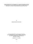
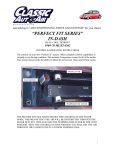
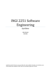
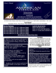
ALC 94 MEASURING AND CONTROL DISPLAY DIMENSIONS: 96X48 MM 600 KHZ READING SPEED 6 DIGIT DISPLAY COUNTING ENCODER A AND B SIGNALS FUNCTIONAL EXTERNAL Z (RESET) INPUT FUNCTIONAL EXTERNAL HOLD INPUT QUADRATURE MODE UP-DOWN COUNTING 2 OR 4 COUPLE CONTACT RELAY OUTPUT SET-1 CAN BE SET RELATED WITH SET-2 OPTIONAL FACTOR VALUE (BETWEEN 0,00001 AND 999999) OPTIONAL DECIMAL POINT BETWEEN 1.AND 5. DIGIT 5 VDC OR 12 VDC ENCODER POWER SUPPLY 11 VARIOS OUTPUT CONTROL MODE OFFSET VALUE IS ADJUSTABLE PASSWORD PROTECTION OPERATION MANUAL INCLUDINGS 1. Technical Specifications……….………………..………………………………………………………………………………… 1 2. Connections…………….………………..……………………………………………………………………………………………. 2 3. Front Panel Definitions….………………………………………………………………………………………………………… 4 3.1. Situation LEDs and Button Functions …………………………………………………………………………… 4 3.2. Usage of Front Panel…………………………………………………………………………………………………….. 5 4. Settings……………………………………………………………………………………………………………………………………. 5 4.1. Setting the device values (Set)………………………………………………………………………………………. 6 4.2. Relay output modes (Output)……………………………………………………….………………………………. 6 4.3. Relay output time (tout)…………………………………………………………………………………………………7 4.4. Relay output positions (out)………………………………………………………………………………………….. 7 4.5. Entering hysteresis (hys-up, hydn)…..…………………………………………………………………………… 7 4.6. Setting constant factor (const)…..…………………………………………………………………………….…. 8 4.7. Decimal point selection (point)………………..……………………………………………………………………. 8 4.8. Entering the offset value (offset)………………….……………………………………………………………….. 9 4.9. Reset with reset button (rst bttn)………………………………………………………………………………….. 9 4.10. Reset with external signal Z (rst inpt)……………………………………………………………………………..9 4.11. Activating the Hold input (Hold.inp)…..………………………………………………………………………… 10 4.12. Hold type selection (Holdtyp)……………………………………………………………………………………….. 10 4.13. Sensor type(NPN/PNP) selection (Sens.typ)……….…………………………………………………………. 10 4.14. Edge counting selection (Countyp)……………………………………………………………………………….. 11 4.15. Returning the factory settings (Fac.def)………………………………………………………………………… 11 4.16. Recording when the energy is off (Record).…………………………………………………………………... 12 4.17. Password protection (Protec)..……………………………………………………………………………………… 12 4.18. Appendix A relay output graphics (Out Menu)………………..…………………………………………….. 13 5. DATA PROTOCOL……………………………………………………………………………………………………………………… 16 6. ERROR MESSAGES……………………………………………………………………………………………………………………. 16 7. WARRANTY CERTIFICATE………………………………………………………………………………………………………..… 17 1. TECHINAL SPECIFICATIONS Electrical Characteristics 24 VAC/DC 50/60 Hz 85-265 VAC 50/60 Hz Power supply Power consumstion 5.5 VA / 4.4 W Maximum Sensor power supply 5 VDC 100 mA (for TTL Sensor) 12 VDC 100 mA (for Push-Pull Sensor) Wiring 2,5 mm² connector terminal A/B Enkoder Pulse ınputs (600 KHz reading speed) Z (External Reset) input (Edge can be selected by menu.) Hold input (edge can be selected by menu.) Inputs Outputs (relays) 2 pieces (optional 4 pieces) 250 VAC 3A (For Resistive load) Relay Serial communication RS-232 (optional) Housing Characteristics Dimensions 96 x 48 x 88 mm Weight 300 gr. Mounting Upper and lower side legs are fixed to the panel Relative Humudity Until the 31 °C %80, above 31°C linear decreasing and at 40 °C %50 nemde çalışır. Stock Temperature -10 - 60 °C Operation Temperature IP Class 0 - 50 °C IP 60 front panel, IP 20 rear panel Dimensions 96 mm 48 mm 46 mm 94mm -1- 2. CONNECTIONS Outputs are optional here. unless specified in order, terminal locations is blank. Hold signal RS-232 COM NO NC COM NO NC TX + - RX GND Z (reset) signal B signal GND A signal +5Vdc or +12 Vdc OUT 4 + + NC NO COM NC NO COM N Power supply 24 VAC / DC or 85 / 265 VAC L OUT 3 OUT 2 OUT 1 WARNINGS 1. Follow the instructions and read the manuel before connecting and using device. 2. Please check the type of power supply before givig energy. 3. Mount the device to the panel robustly against to the drops, vibration and shaking during utilization. 4. Make the sensor connections while energy is off, never change the connections while energy is on. 5. Keep away from the high voltage. 6. Don’t expose to the sunbeams and heating source directly in the utilization place.. 7. ALC94 Endustrial Control Device propor only for room conditions, don’t use outer enviroment 8. Clean the device only with a moist duster, never use water, thinner etc… 9. Adapt the relay to the given technical relay output values. 10.There is no part for replacing or repairing by user. Plase call the service in this situations. -2- Incremental Encoder Connection Encoder Z Signal Encoder B Signal Encoder A Signal Encoder – Supply Pin Encoder + Supply Pin Earth Incremental Encoder Device Supply 85/265 VAC or 24 VAC/DC Incremental Linear Scale Connection Encoder Z Signal Encoder B Signal Encoder A Signal Encoder – Supply Pin Encoder + Supply Pin Earth Incremental Linear Scale Device Supply 85/265 VAC or 24 VAC/DC -3- 3. FRONT PANEL DESCRIPTIONS Button Functions In ALC94 device buttons have two fuctions: Programme Mode Operation Mode : Function for programming. : Function for operating. 3.1. Situation Led’s and Button Functions 1. PROG Button (Programme mode): To enter the MENU parameter and save the entered parameter. 2. LEFT BUTTON (Programme mode): To change the decimal parameter, while entering the parameter value. 3. UP BUTTON (Programme mode): To transition in the menu and incresase the value of the selected parameter. Operation mode: To see the max measured value. 4. DOWN BUTTON (Programme mode): To transition in the MENU and decresing the value of the selected parameter. Operation mode: To see the min mesured value. 5. RST BUTTON (Programme mode): To escape without saving the entered value. Operation mode: To reset the value of the display. Situation LEDs 6. 7. 8. 9. Out-1 output condition LED: Out-1 output signs when it gets voltage. Out-2 output condition LED’i: Out-2 output signs when it gets voltage. Out-3 output condition LED’i: Out-3 output sign when it gets voltage. (if exist) Out-4 çıkışı durum LED’i: Out-4 çıkışı enerjilendiğinde yanar. (Varsa) -4- 3.2. Front Panel Usage 1. RST Function: While RST BTN menu is holding as reset RST ( RST ) position and the device is operation mode pressing make zero the display value or return to ofset if it is given. The device continue to counting. Pressing again repeat the operation. Detailed will be descripted section 5.1.2 2. Displaying the Min and Max Values: While the device is holding on operation mode pressing and holding down button ( ) displays the all measured MIN VALUES. Pressing and holding up button ( )) displays the all mesured MAX VALUES. Preesing the ESC button( )while displaying the values will be reseted these min or max values. 4. SETTING ENTERING THE MENU ANG CHANCING THE PARAMETERS: While the device is holding on operation mode to pass to programming mode press and hold on button and press RST button.Enter the menu after seeing “ on the display. You will see “ menu on the display firstly. RST If the password is activated the device asks for password while chancing the parameter. If you enter with wrong password the device gives FALSE message and you can enter the menu but you can’t change the values. ıf you enter with the correct password the device gives TRUE message and you can change the values. Enter the password RST True message come with the correct password. Value is changable . False message come with the wrong password. Value is unchangable . The desired menu is selected by up( ) and down ( ) buttons. Press ( ) button to enter the menu which you want to change. The menu contents can be changed by pressing PRG again . The values can be changed by using UP and DOWN buttons. To save the values press PRG. Pres ESC ( ) button to exit without saving the changed values. Press ESC button to return the main menu or operation mode . -5- 4.1. Setting The Device Value (Set) Entering the set value to the device is made by Set-1 and Set-2 menus (If they exist you can also use Set-3 or Set-4). Each menu controls an output. When the entered set value is reached, related relay become active, the relay’s LED that is active sign. When the relay drop, also LED sign out. There are different output functions. These outputs will be described under the Output menu. To enter the Set menu, enter the programming menu before.To enter the menu, press PRG button while holding the PRG ,press RST button. First Set-1 menu appears on display, when you use UP button Set-2 menu is appeared (ıf they exist also Set-3, Set4 ). Press PRG button to change menu content, the value that is present is appeared on the display. When you press PRG button again the rightmost digit starts flashing. The intended value is set by using UP-DOWN buttons. To pass the other digit pres LEFT button. The digit will pass leftside for each LEFT button pressing. If desired, point place is changed by POINT menu point place should be changed. After the setting value press PRG button to save. Press RST button if you want to exit without saving. The other set menus are setting by this way. RST . When press the PRG button the right digit flashing on display. Setting by UP-DOWN button. The digit shift to the leftside by pressing left button. Is saved by pressing the PRG button. Set-3 and Set-4 menu are appeared in the 4 relay product model. 4.2. Relay Output Modes(Output) Output menu allows to the relay outputs to give different outputs by the setted values. There are 11 different output types. Output types are exist in the part of EK-A with detailed graphics. To select any output modes, the programming mode is entered by pressing RST button while holding PRG button. Output menu are found by using UP-DOWN button. When press the PRG button menu content is appeared When you press PRG button again menu content flash. Mod selection is made by UP-DOWN button. The selection is saved by press PRG button. RST When the press PRG button in the selection display the right digit flash. The desired selection is set by using UPDOWN button. It is saved by pressing PRG button. -6- 4.3. Relay Output Time (tout) The “Tout menu” provides to push the relay outputs during the setted time. If the time is 0 (zero) there will be written HOLD on the display. In this case, relays. In this position the relays will be pulled during the values above the set values. To enter the output time, while holding the PRG button press the RST button in the operation mode. Tout-1 or Tout-2 (if exist Tout-3 Tout-4) menus are founded by UP-DOWN button. Menu content is displayed by pressing PRG button. When press the PRG button again right digit start to flash. The value is set by UP-DOWN button. The digit shift to the left by pressing left button. The value is saved by using PRG button. Point place is constant. RST . The right digit flash when press the PRG button on the display. The desired selection is set by UP-DOWN button. It is saved by pressing PRG button. 4.4. Relay Output Positions (out) - Out-1 and out-2 (if exist out-3, out-4) menus determines the relay’s standart position. Relay remain in the passive position at the Nclose option, it pulls with the set value. In the Nopen option relay stay active position, when the set point is reached ıt pass inactive position. RST Selection flash in the display when press the PRG button. Desired selection is set by UP-DOWN button. It is saved by pressing PRG button. 4.5 Entering Hysteresis (hys-up, hys-dn) Hysteresis value can be entered to the device through this menu. Hysteresis value is entered to prevent the relay contact flicker that is consist of vibration when the device reach the Set value. Below the setted value the relays give contact On or Off. During the hysteresis value nothing can be done, So negligible value should be selected. Hysteresis value is entered with hys-up and hys-dn menu. Hys-up values are active when the exceed the Set value, Hys-dn values are active when drop from the set point. To enter the Hysteresis value to the device, programming mode is entered by press the RST button while holding the PRG button. Hys-up, Hys-dn menus are found by UP-DOWN button. When press the PRG -7- button, the right digit flash. The intended value is set by UP-DOWN button. The digit shift to the left side by pressing the left button. The value is saved by pressing PRG button. RST . The right digit flashed by pressing the PRG button on the display. İntended value is set by UP-DOWN button. The digit shift to the left side by using the left button. The value is saved by pressing PRG button. 4.6. Setting Constant Factor Value (const) Const menu allows to show different resolutioned sensors as desired value on the display by entering the multiplier values. It determines the display value of each edge and pulse. For example, 0,025 is set in CONST menu for 25 micron resolution sensor. For 5 micron resolution sensor, 0.005 is set. In this case when the sensor goes 100mm, 100 value is appaered on the display. To set Const menu, while holding the PRG button press the RST button to enter programme mode. Const menu is founded by UP-DOWN button. While in the Const menu if you press the PRG button the multiplier value that is entered is appeared on the display. When you press PRG button again the right digit flash. The desired value is set by UP-DOWN button, the digit shift to the left side by pressing the left button. After setting the intented value, if you press the PRG button the point flash. With the UP-DOWN button point place is set. When press the PRG button the value is saved. Pres RST button to go back to operation mode without saving the value. RST . When press the PRG button, the right digit that is on the display flash. The intended value is set by UPDOWN button. The digit shift to the left by using LEFT button. When press the PRG button the point flash. The point place is set by UP-DOWN button. Press PRG button to save. 4.7. Decimal Point Position Selection (Point) The value’s precision that is on the display is set by here. By changing the decimal point that is on the screen, the value is selected as how much resolution after the point. Also Set and Hysteresis menu point place is set by here. To set the Point menu, programming mode is entered by pressing RST button while holding PRG button. Point menu is founded by UP-DOWN button. While you are in the Point menu, setted point position is appeared when press the PRG button. When press the PRG button again the point flash. Intended point position is set by UP-DOWN button. The value is saved by PRG button. RST . When press the PRG button, the right digit that is on the display flash. The intended value is set by UPDOWN button. The digit is shifted to the left side by pressing the left button. Press PRG button to save. -8- 4.8. Entering The Offset Value(offset) The Offset value is entered to the device by this menu. Return the entered offset value, when press the PRG button or the signal comes from Z input. If offset is zero, when press the RST button, 0(zero) is written on the display. To set the Offset menu, programming mode is entered by pressing RST button while holding PRG button. Offset menu is found by UP-DOWN button. Setted point position is appeared when press the PRG button. When press the PRG button again,the point flash. Intended position is set by UP-DOWN button. The selection is saved by PRG button. RST . When press the PRG button, the right digit flash. The intended value is set by UP-DOWN button. The digit is shifted to the left side by pressing the left button. Press PRG button to save. 4.9. Reset with Reset Button (rst btn) This menu provides to activating the RST button that is on the front panel. The display value is reseted or returned to the Offset values if press the RST button while active condition in operating mode. To activating the RST button, programming mode is entered by pressing the RST button while holding the PRG button. Rstbtn menu is found by UP-DOWN menu. Menu content is appeared by pressing the PRG button. When press the PRG button again,the selection flash.The intended selection is set by UP-DOWN button (if select RESET it is active, if you select NONE it is passive. The value is saved by PRG button.. RST When press the PRG button selection flash on the display. Intended selection is set by UP-DOWN button. Press PRG button to save. 4.10 Reset with External Z Signal (rst.inp) Activating the Z signal, you can reset on the device display by an external encoder signal Z or switch. While the Z input is activating, One of the edge which will be reset is selected, rising edge (rise) or falling edge (fall). If Z input is not wanted to use, none option is selected. To activating the Z input, programming mode is entered by pressing the RST button while holding PRG button. Rst.inp menu is found by UP-DOWN button. Menu content is appeared by pressing the PRG button. When press the PRG button again, the selection flash. The intended selection is set by UP-DOWN button. The value is saved by PRG button RST -9- When press the PRG button selection flash on the display. Intended selection is set by UP-DOWN button. Press PRG button to save. 4.11. Activating the Hold Input (Hld.inp) The value that is on the display is frozen while the Hold input is active While the Z input is activating, One of the edge which will be reset is selected, rising edge (rise) or falling edge (fall). Counting processing is not continued without cutting the signal in the Hold input even the counting is done or not. If the Hold input is not wanted to use, none option is selected. To activating the Hold input, programming mode is entered by pressing the RST button while holding PRG button. Rst.inp menu is found by UP-DOWN menu. Menu content is appeared by preesing the PRG button. When press the PRG button again, the selection flash. The intended selection is set by UP-DOWN button. The value is saved by PRG button. RST When press the PRG button selection flash on the display. Intended selection is set by UP-DOWN button. Press PRG button to save. 4.12. Hold Type Selection (Hldtyp) The type of Hold input is selected by this menu. When Hold signal is applied in Count option, the value on the display is frozen and the device continue to count in background. When the Hold input is cut it continues to count from the counted value. The counting is not done in the background in Nocount option. It continues from the value that is on the display. To activating the Hold input, programming mode is entered by pressing the RST button while holding PRG button. Hld.typ menu is found by UP-DOWN button. Menu content is appeared by preesing the PRG button. When press the PRG button again, the selection flash. The intended selection is set by UP-DOWN button. The value is saved by PRG button. RST . RST When press the PRG button selection flash on the display. Intended selection is set by UP-DOWN button. Press PRG button to save. 4.13. Sensor Type (NPN/PNP) Selection (Sns.typ.) The used sensor type can be selected by this menu. Depending on the type of sensor output, ıt is provided to working with different sensors by doing the NPN and PNP selection. To select the Sensor type, programming mode is entered by pressing the RST button while holding the PRG button in operating - 10 - mode. Snstyp menu is founded by UP-DOWN button. Menu content is appeared by pressing the PRG button. When press the PRG button again,the selection flash. The intended selection is set by UP-DOWN button. The value is saved by PRG button. RST When press the PRG button selection flash on the display. Intended selection is set by UP-DOWN button. Press PRG button to save. 4.14. Edge Counting Option (Cnt.typ.) Edge counting number of encoder A and B signals are selected by edge counting selection.counting options are 1,2, or 4. If incremental encoder is connected, select 1 to see the value that is on the display in terms of pulse. When Linear encoder is connected, option 4 (quadrature mod) is selected for a more sensitive mesaurement. To change the edge counting option, programming mode is entered by presssing the RST button while holding the PRG button in operation mode. Cnt.typ. menu is founded by UP-DOWN button. Menu content is appeared by pressing the PRG button. When press the PRG button again,the selection flash. The intended selection is set by UP-DOWN button. The value is saved by PRG button. RST When press the PRG button selection flash on the display. Intended selection is set by UP-DOWN button. Press PRG button to save. . 4.15.Returning to Factory Settings (Fac. Def.) It is possible to return the first fabrication device settings by Factory menu. The device’s all settings change in this situation,So it is useful to recording the settings. To return the first settings, device asks a password,the password is 454.To return the factory settings, programming mode is entered by pressing RST button while holding PRG button in operation mode. Fac. def menu is founded by UP-DOWN button. When press the PRG button, “yes”, “no” options are appaeared. If press the PRG button in “Yes” option, a display that asks password come. Password value is set by UP-DOWN button.The digit shift to the left side by left button. When press the PRG button, device return the factory settings. RST - 11 - 4.16.Recording When The Energy is Off (Record) “Data menu” provides to keep in the memory when the device’s energy is off. When the record option is active in Data menu, the displayed value is recorded in the memory,when giving the energy again the device continue to work from the stayed value. When the device is off the displayed value starts from 0(zero). To change the Data menu, programming mode is entered by pressing RST button while holding PRG button in operation mode. Record menu is founded by UP-DOWN button. Menu content is appeared by pressing PRG button. When press the PRG button again,the selection flash. The intended selection is set by UP-DOWN button. The value is saved by PRG button. RST When press the PRG button selection flash on the display. Intended selection is set by UP-DOWN button. Press PRG button to save. 4.17. Password Protection (Protec) Activating the password protection prevent to be changed the menu parameters by unresponsible people. When the Protec menu is in “yes” position, konumuna alındığında, device can be enter the menu. Parameter values can be displayed. When you want to make changes, the password is asked. When the password is written wrong, you can not change. If the password correct you can make changes. When the Protec menu is in “no” position, the password is not asked. When the Protec menu is made ON Recode menu is added in the menu titles. Password creation is made by there. To open the Protec menu, programming mode is entered by pressing RST button while holding PRG button in operation mode. Protec menu is founded by UP-DOWN button. Menu content is appeared by pressing the PRG button. When press the PRG button again, the selection flash. The intended selection is set by UP-DOWN button. The value is saved by PRG button. RST When press the PRG button selection flash on the display. Intended selection is set by UP-DOWN button. Press PRG button to save. When Protec menu is made ON position, Recode menu is open in the menu titles. Recode menu provides device to define the password. If the password is not entered the current password is 000. When press the PRG button, the right digit flash. The value is set by UP-DOWN button. The value shift to the left side by left button. The password is saved by PRG button. When the password is forgotten, the current password is 456. When press the PRG button the right digit flash on the display. The value is changed by UP-DOWN button. When press the left button, the digit shift to the left side.The value is set by UP-DOWN button. The value is saved by pressing the PRG button. The password is defined. - 12 - 4.18. Appendix A Relay Output Graphics (Out Menu) Out 00 When the Out mode is selected 0, Out-1 and Out-2 do not give any output. Out 01 When the count value is over then the Set 1 value,OUT 1 gives an output in this mode (relay-1 pulls). If TOUT-1 (Relay-1 pull time) HOLD is selected, the OUT-1 will be holded up to count value is below SET1. When count value exceed the SET-2 value OUT-2 gives an output and if TOUT-2 HOLD is selected the OUT-2 is holded as a pulled until the count value fall down the SET-2. If TOUT-1 and TOUT-2 is selected with holding time, OUT-1 and OUT-2 will be holded during setted holding time. Out 02 Out 03 When count value rise from the SET-1, value OUT-1 gives an output and if it rise up from SET-2 value OUT-2 gives an output. Even ıt falls from the SET value ,relays do not stop until the RESET come, but when the RESET come ıt stops. If the time is entered for the outputs,relays gives an output and stop during this time,relays do not gives output until the RESET comes,even the fall or rise from the SET values. Out 03 ou OUT-1 gives an output when the count value rise up to SET-1 and stop when it fall down. When rise up to SET-2 value OUT-2 gives an output and count value is fixed. Even the puls is come to device by encoder,count value is not changed without RESET coming, but when the RESET come, the count value and outputs are reset. - 13 - Out 04 OUT-1 output dependent on OUT-2. TOUT-2 should be selected with time. OUT-1 gives an output,the count value rise up to SET-1 value and ıt stop when ıt fall down, OUT-2 gives an output when ıt rise up to SET-2 value and count value is fixed. End of the TOUT-2 time outputs and count value is reset automatically. Before the TOUT-2 time is not up, if RESET comes,the outputs and count number are reset. Out 05 This is the Output-4 state that counting after the set-2 value. OUT-1 output is dependent on OUT-2. TOUT-2 shoul be selected with time. OUT-1 gives an output,the count value rise up to SET-1 value and ıt stop when ıt fall down, OUT-2 gives an output when ıt rise up to SET-2 value, End of the TOUT-2 time outputs and count value is reset automatically. Before the TOUT-2 time is not up, if RESET comes,the outputs and count number are reset. Out 06 OUT-1 gives an output,the count value rise up to SET-1 value, OUT-2 gives an output when ıt rise up to SET-2 value and outputs stop end of the TOUT time. If the TOUT times is selected as a HOLD,even count value fall down the SET value, outputs do not stop. When count value reach the zero (OFFSET), the outputs are reset,also when the RESET comes ,count value and outputs are reset. Out 07 OUT-1 gives an output,the count value rise up to SET-1 value and TOUT-1 time leave at the end. If TOUT-1 time is selected as a HOLD, OUT-1 stop when the count value fall down the SET-1. OUT-2 gives an output when rise up to SET-2 value and stop end of the TOUT-2 time. If TOUT-2 time is selected as a HOLD,OUT-2 do not stop, even the count value fall down the SET-2 value. When the count value reach the zero (OFFSET) ,the OUT-2 output is reset,also when the RESET comes the count value and outputs are reset. - 14 - Out 08 While the count value is under the SET-1 value,OUT-1 gives an output and when rise up, ıt stop, OUT-2 gives an output when the rise up to SET-2 value, and ıt stop when fall down the SET-2 value.the count value and outputs are reset when RESET comes. Out 09 The outputs (TOUT) should be selected as a time in this mode. When the count value’s each passing from the SET-1 value, OUT-1 gives an output in TOUT-1 time and stop, each passing the SET-2 value ,OUT-2 gives an output and end of the TOUT-2 time ıt stop.When RESET comes,outputs and count value are reset. Out 10 TOUT time sholud be selected as a HOLD. OUT-1 gives an output until the count value reach the SET-2 value and when it reach OUT-1 stop, OUT-2 start to pull. OUT-2 pulls until the count value reach the SET-1 value and when ıt reach OUT-2 stop and again OUT-1 pulls. - 15 - 5. DATA PROTOCOL ALC-94 RS-232 parameters are as follows. There isn’t any settings on the device. There is single direction from communication device to reciever terminal. Data format : RS232 EOL (16bit data + EOL (end of line character) ) Baud rate : 57600bps Data bits :8 Stop bits :1 Parity : none 6. ERROR MESSAGE . When the value is too high, ( 999999 ) is written. Skala or format value sholud be reduced. . When the value is too low, ( -999999 ) is written. Skala or format value should be reduced. - 16 - 7. WARRANTY CERTIFICATE Product : ALC 94 UNI 85/265 VAC RS-232 24 VAC/DC SSR output Serial No : …………………………………… This product has 2 years warranty against to production flaw. The situations that is not included by the warranty: - Mechanical injuires - The shipping damage - User errors The other conditions is covered by manufacturer’s warranty. Sign, Stamp - 17 - ATEK SENSOR TECHNOLOGIES A.S. Cevizli Mah. Bagdat Cad. Guven Sok. No:11 TR-34846 Maltepe / Istanbul - TURKEY Tel: +90 (216) 399 44 04 Fax : +90 (216) 399 44 02 Web: www.ateksensor.com E-Posta: [email protected]