1
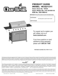
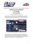
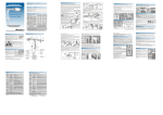
Owner’s Manual Form AF410 29354 Hunco Way Suite A Lake Elsinore, CA 92530 www.americanfireglass.com H-BURNER DECORATIVE VENTED GLASS BURNER General Assembly, Installation and Operation Instructions ATTENTION! READ INSTRUCTIONS CAREFULLY BEFORE ASSEMBLY OR USE Tools Needed Adjustable Wrench, Pipe Wrench, Pipe Sealing Compound and hand held lighter Burner Systems: SAFETY PILOT KITS: SS-H-12; MATCH LIT (12” H-Burner Style) SPK-N-M (MANUAL) SS-H-18; MATCH LIT (18” H-Burner Style) SPK-N-O (ON/OFF REMOTE) SS-H-24; MATCH LIT (24” H-Burner Style) SPK-N-V (VARIABLE REMOTE) SS-H-30; MATCH LIT (30” H-Burner Style) SS-H-36; MATCH LIT (36” H-Burner Style) All Burners for Natural Gas Only WARNING: If the information in this manual is not followed exactly, a fire or explosion may result causing property damage, personal injury or loss of life. — Do not store or use gasoline or other flammable vapors and liquids in the vicinity of this or any other appliance. WARNING This is a vented gas appliance for use only in a solid-fuel burning fireplace constructed on non-combustible material with a fully functional chimney flue which must vent all products of combustion. When operating, the chimney DAMPER MUST BE FULLY OPEN INSTALLER: Leave this manual with the appliance. CONSUMER: Retain this manual for future reference. WHAT TO DO IF YOU SMELL GAS • Do not try to light any appliance. • Do not touch any electrical switch; do not use any phone in your building. • Immediately call your gas supplier from a neighbor’s phone. Follow the gas supplier’s instructions. • If you cannot reach your gas supplier, call the fire department. — Installation and service must be performed by a qualified installer, service agency or the gas supplier. 1. Improper installation, alteration, service or maintenance can cause property damage, personal injury or loss of life. Read these instructions thoroughly before installation. For assistance or additional information, consult your gas log dealer, qualified installer, service agency or gas supplier. Installation must conform with local codes or, in the absence of local codes, with the National Fuel Gas Code, ANSI Z223. 1/ Latest Edition IMPORTANT INFORMATION • Due to high temperatures, the appliance should be located out of traffic and away from furniture and draperies. • Children and adults should be alerted to the hazard of high surface temperatures and should stay away to avoid burns or clothing ignition. • Young children should be carefully supervised when they are in the same room with the appliance. • Do not place clothing or other flammable material on or near the appliance. • Any safety screen or guard removed for servicing an appliance must be replaced prior to operating the appliance. • Installation and repair should be done by a qualified service person. The appliance should be inspected before use and at least annually by a professional service person. More frequent cleaning may be required due to excessive lint from carpeting, bedding material etc. It is imperative that control compartments, burners and circulating air passageways of the appliance be kept clean. • WARNING: Any change to this appliance or its controls can be dangerous. • WARNING: Failure to keep the primary air opening(s) of the burner clean may result in sooting and property damage. • Keep appliance area clear and free from combustible materials, gasoline and other flammable vapors and liquids. • DO NOT use this room appliance if any part has been under water. Immediately call a qualified service technician to inspect the appliance and to replace any part of the control system and any gas control that has been under water. • WARNING: Before installing in a solid-fuel burning fireplace, the chimney flue and firebox must be cleaned of soot, creosote, ashes and loose paint by a qualified chimney cleaner. • WARNING: Do not allow fans to blow directly into the fireplace. Avoid any drafts that alter burner flame patterns. • WARNING: Do not use a blower insert, heat exchanger insert or any other accessory not approved for use with this heater. • A fireplace screen must be in place when the appliance is operating and, unless other provisions for combustion air are provided, the screen shall have an opening(s) for introduction of combustion air. • Solid fuels shall not be burned in a fireplace where this appliance is installed. • WARNING: Glass doors must be fully opened when appliance is in operation to allow for safe combustion, cooling of components and venting. • Any outside air ducts and/or ash dumps in the fireplace shall be permanently closed at the time of appliance installation. • Avoid contact with the objects, chassis or another part which may be hot during operation. This appliance is only for use with the type of gas indicated on the box. This appliance is not convertible for use with other gases. BE CAREFUL if not installed, serviced and used correctly per these instructions, this product can cause serious personal injury, property damage or lost of life. CARBON MONOXIDE POISONING MAY LEAD TO DEATH When used without fresh air, decorative gas appliances may give off carbon monoxide, an odorless, colorless, poisonous gas. Some people, pregnant women, persons with heart or lung disease, anemia, persons under the influence of alcohol and persons who live at high altitudes are more affected by carbon monoxide than others. Early signs of carbon monoxide poisoning resemble the flu and include; headache, dizziness and/or nausea. If you have these symptoms, the burner or the appliance may not be installed or working properly, or the flue may be blocked. GET FRESH AIR AT ONCE! Verify that the H-Burner is properly arranged and have the heater and chimney flue serviced before using again. WARNING—Proposition 65 Statement If not installed, operated and maintained in accordance with these instructions, this product could expose you to substances in fuel or from fuel combustion which are known to the State of California to cause cancer, birth defects or other reproductive harm. 2. IMPORTANT INFORMATION THIS H-BURNER MUST BE INSTALLED IN A FULLY VENTED SOLID-FUEL BURNING FIREPLACE WITH A WORKING FLUE CONSTRUCTED OF NON COMBUSTIBLE MATERIAL. DAMPER MUST BE WIDE OPEN WHILE BURNING OPEN A WINDOW AN INCH OR TWO FOR FRESH AIR WHEN USING YOUR H-BURNER SOLID FUELS SHALL NOT BE BURNED IN A FIREPLACE WHERE A DECORATIVE APPLIANCE IS INTALLED. PARTS LIST 1.) H Burner 12”, 18”, 24’, 30”, 36” 2.) Damper Clamp 3.) Inlet Fitting 1/2” x 1/2” Flared Brass Fitting 4.) 1/2” x 1/2” Flared MIP Fitting 5.) 1/2” x 12” Flex Connector 1. 2. 4. 3. 5. IMPORTANT INFORMATION (continued) A fire place screen must be in place when the H-Burner is in operation and, unless other provisions for combustion air are provided, the screen shall have opening(s) for introduction of combustion air. The minimum inlet gas supply pressure for the purpose of input adjustment shall be 6 inches of water column on natural gas. The maximum inlet gas supply pressure shall be 7 inches of water column on natural gas . The installation and the provision for combustion and ventilation air must conform with the NATIONAL FUEL GAS CODE ANSI Z223.1 latest edition. The H-Burner and its individual shutoff valve must be disconnected from the gas supply piping system during any pressure testing of that system at test pressures in excess of 1/2 psig (3.5 kPa). The H-Burner must be isolated from the gas supply piping system by closing its individual manual shutoff valve during any pressure testing of the gas supply piping system at test pressures equal to or less than 1/2 psig (3.5 kPa). The area around the H-Burner must be clear and free from combustible materials, gasoline and any other flammable vapors and liquids. Do not use this appliance if any part has been under water. Immediately call a qualified service technician to inspect the appliance and to replace any part of the control system and any gas control which has been under water. Important: Use with other manufacture parts, controls, remotes, parts and accessories which are not design, tested with American Fireglass products is prohibited and will void all warranties. Liability for bodily injures or property damage will not be accepted by American Fireglass if installation and / or product usage does not comply with this H -Burner. WARNING! CHECK FOR PROPER VENTING A properly sized, unobstructed chimney will normally vent all fumes and products of combustion. Any odor or smoke detected inside the room is an indication that the flue is not properly removing the combustion products. SHUT OFF THE BURNER IMMEDIATELY! THE CAUSE OF THE VENTING PROBLEM MUST BE DISCOVERED AND CORRECTED BEFORE CONTINUED USE OF THE H-BURNER. Continued use with improper venting may cause damage to your fireplace, room and furnishings and could cause serious illness. If improper venting is suspected, IMMEDIATELY HAVE H-BURNER AND CHIMNEY FLUE SERVICED. Periodically examine and clean the venting system. Once a year, a qualified agency should examine and clean the venting system of your solid fuel burning fireplace. 3. GENERAL INSTALLATION INSTRUCTIONS WARNING: Failure to position the parts in accordance with these diagrams or failure to use only parts specifically approved with this appliance may result in property damage or personal injury.. STEP ONE PREPARATION: 1. Verify that the H-Burner is correctly matched. FIGURE 2 2. Turn off Fireplace Gas Supply (Figure 1A) . FLUE 3. Thoroughly clean fireplace floor of any ashes and have a qualified chimney cleaner insure that the chimney flue and firebox are free of soot, creosote, and loose paint. 4. Attach Damper Clamp (Figure 2A) over edge of fireplace Damper Blade (Figure 2B) to prevent damper from fully closing accidentally. If unable to attach damper clamp, drill a hole (or holes) in the damper or remove it completely. mp la rC pe m Da F re igu 2A 2B re u e Fig lad B er mp a D FIGURE 1 Gas Supply Valve (Location may vary per installation) Opening Height Minimum (See Page 5) Burner Ports Facing Flue 2” Gas Valve Key Side View Burner Pan Positioning In Fireplace (side view) 1. Place BURNER inside firebox as far as 2” (see figure 2) from the rear wall. Center the BURNER left to right. 2. Be sure the FLEX CONNECTOR is not positioned over the BURNER or exposed to direct flame. IMPORTANT: THE CHIMNEY DAMPER MUST BE WIDE OPEN AND FIXED IN A MANNER TO MAINTAIN A PERMANENT FREE OPENING AT ALL TIMES AS OUTLINED ABOVE. THE AREA OF THE FLUE MUST BE NOT LESS THAN 1/10 THE AREA OF THE FIREPLACE OPENING. THIS H-BURNER MUST BE INSTALLED IN A FULLY VENTED METAL OR MASONRY FIREPLACE WITH A WORKING FLUE THAT IS SAFE FOR BURNING A WOOD FIRE. THE FLUE MUST BE FREE OF ANY OBSTRUCTIONS AND MUST EXHAUST ALL PRODUCTS OF COMBUSTION. DAMPER MUST BE FULLY OPEN BEFORE LIGHTING OR BURNING FOR PROPER VENTILATION. 4. “H” BURNER SIZE FIREBOX FRONT WIDTH FIREBOX REAR WIDTH FIREBOX DEPTH FIREBOX HEIGHT CHIMNEY DIAMETER MIN PERMANENT CHIMNEY OPENING BTU MIN 6 W.C. BTU MAX 7 W.C. 12” 18” 12” 14” 16” 6” 29 Sq” 130,000 150,000 18” 24” 18” 14” 16” 7” 39 Sq” 135,000 155,000 24” 30” 24” 14” 16” 7” 51 Sq” 140,000 160,000 30” 36” 30” 14” 18” 8” 64 Sq” 145,000 165,000 36” 42” 36” 14” 24” 9” 64 Sq” 150,000 170,000 H-BURNER SERIES TECHINAL DATA SHEET Step 1. Minimum Depth 14” Left Side Gas Supply Line Locate Valve / Pilot Assembly to the front of the fireplace close to the side walls. Rear Width (Not less than H-Burner size) Figure 3 2” to 3” from rear wall Turn Burner for left side gas supply line Burner Ports Facing Right Side Gas Supply Line Locate Receiver outside the Fireplace Front Width (Minimum 6” greater than H-Burner size) Gas Valve Key Burner Positioning In Fireplace (Top View) 1. Place BURNER inside firebox as far as 2” to 3” (see figure 3) from the rear wall. Center the BURNER left to right. 2.) Be sure the FLEX CONNECTOR is not positioned away from the BURNER or exposed to direct flame. GAS SUPPLY CONNECTION 2. Apply pipe compound to thread end of gas supply pipe. Thread 1/2” FIP x 1/2” flare elbow onto gas supply pipe and wrench tighten. 2.) Apply pipe compound onto threads on H-Burner and thread 1/2” FIP x 1/2” flare fitting then wrench tighten. 3.) Position H-Burner inside firebox (see figure 3), connect aluminum flex connector to the inlet of burner and to the 1/2” FIP x 1/2” flare elbow on gas supply pipe and wrench tighten. Note: Do not kink or break aluminum flex connector tube. 4.) Turn gas supply to fireplace on. 5.) Test all connections for leaks with soapy water solution. If solution bubbles, turn off gas supply, retighten fitting and recheck. If leaks are found, turn off gas immediately and leave WARNING: DO NOT FLAME TEST FOR LEAKS 5. INSTALLTION INSTRUCTIONS LIGHTING AND OPERATION OF H-BURNER FILLING H-BURNER WITH GLASS Step 3 1.) Begin by completely covering BURNER TUBES (See figure 4) with glass first. 2.) Focus first on covering the entire BURNER TUBES before spreading evenly within the firebox floor. 3.) Use the entire bag of glass that is provided with the burner. 4.) Spread the remaining glass evenly on the firebox floor without exposing BURNER TUBES. IMPORTANT: CHIMNEY DAMPER MUST BE WIDE OPEN MANUAL MATCH LIGHTING Standard Match Lit (H -BURNER FOR NATURAL GAS ONLY) 1. Place lighted match (See Figure 4) on glass near inlet end of burner. DO NOT HOLD MATCH IN HAND! Move away from front of fireplace. 2. Slowly open FIREPLACE GAS SUPPLY VALVE and wait for burner to light. 3. Adjust FIREPLACE GAS SUPPLY VALVE for desired flame height. Figure 4 WARNING: DO NOT ALLOW FLAMES FROM H-BURNER EXCEED THE HEIGHT OF THE FIREPLACE OPENING. 4. SHUTDOWN: Close FIREPLACE GAS SUPPLY VALVE completely. WARNING:DO NOT LEAVE BURNER UNATTENDED, WHILE H-BURNER IS BURNING. WARNING: DO NOT FLAME TEST FOR LEAKS 6. LIGHTING AND OPERATION OF SAFETY PILOT KITS IMPORTANT! CHIMNEY DAMPER MUST BE WIDE OPEN! THE FLUE MUST VENT ALL PRODUCTS OF COMBUSTION. DAMPER AND GLASS DOORS MUST BE FULLY OPEN BEFORE LIGHTING OR BURNING FOR PROPER VENTILATION AND TO PREVENT HEAT DAMAGE TO THE VAVLE. PILOT LIGHTING INSTRUCTIONS SAFETY MANUAL CONTROL VALVE SKP-N/P-M 1. Turn VALVE KNOB to “PILOT” position. KNOB CONTROL INDICATOR PILOT ADJUMENT SCREW 2. Depress and hold until air is bled and gas flows to Pilot . 3. Light Pilot with a Match or Lighter. 4. Once Pilot is lit, continue to depress and hold until the Pilot flame remains lit (approximately 30 to 60 seconds). 5. If Pilot does not remain lit, depress and turn Valve Knob clockwise to “OFF” position and wait at least 5 minutes to allow gas to dissipate. Repeat steps 1 thru 4. WARNING! DO NOT OPERATE BURNER WITH VALVE HEAT SHIELD. VALVE PLUG VALVE KNOB 1. Turn VALVE KNOB counter clockwise to “ON” position 2. Adjust the burner flame height by turning the valve knob clockwise to lower and counter-clockwise to raise up to full on. KNOB OPERATION IMPORTANT INFORMATION ON YOUR VALVE GAS CONTROL It is intended to prevent premature valve failure and voiding of warranty. Replace immediately if removed for any reason. The “EASY Safety Control Valve must be protected to a maximum ambient temperature of 225° F. Excessive heat to the valve is indicated by melted plastic or wiring on the valve body and is not warrantable. Allow an adequate period of cooling after use before closing glass doors. NEVER operate your BURNER with glass doors closed. BURNER OPERATION FOR ON / OFF FULL ON LOWER OR PILOT POSITION SAFETY ON / OFF CONTROL VALVE SKP-N/P-O 1. See above instructions on Pilot Lighting Instructions 2. Turn VALVE KNOB to “ON” position. (See Knob Operation) RECEIVER SLIDE SWITCH IN “REMOTE” POSITION 3. Slide switch on the RECEIVER to “REMOTE” position. 4. Consult Operating Instructions for Accessory Control. 5. Adjust the burner flame height by turning the valve knob clockwise to lower and counter-clockwise to raise up to full on. ON/OFF SOLENOID DC POWER FROM THE RECEIVER OPERATES THIS UNIT. DO NOT CONNECT TO A 115V AC LINE. THE RECEIVER HAS 3 POSITIONS; “OFF”, “FULL ON” AND “REMOTE ACCESS ON” Note:Consult Operating Instructions for Accessory Control. 7. LIGHTING AND OPERATION OF SAFETY PILOT KITS AND PILOT ASSEMBLY IMPORTANT! CHIMNEY DAMPER MUST BE WIDE OPEN! THE FLUE MUST VENT ALL PRODUCTS OF COMBUSTION. DAMPER AND GLASS DOORS MUST BE FULLY OPEN BEFORE LIGHTING OR BURNING FOR PROPER VENTILATION AND TO PREVENT HEAT DAMAGE TO THE VAVLE. BURNER OPERATION FOR VARIABLE FLAME HEIGHT SAFETY VARIABLE CONTROL VALVE SKP-N/P-V 1. See above instructions on Pilot Lighting Instructions PILOT ADJUMENT SCREW KNOB CONTROL INDICATOR 2. Turn VALVE KNOB to “ON” position. (See Knob Operation) 3. Slide switch on the RECEIVER to “REMOTE” position. 4. Consult Operating Instructions for Accessory Control. 5. Depress the “ON/HI” button on the TRANSMITTIER until a click Is heard. The burner will then light to “FULL ON.” DC POWER FROM THE RECEIVER OPERATES THIS UNIT. DO NOT CONNECT TO A 115V AC LINE. Note:Consult Operating Instructions for Accessory Control. DC VALVE MOTOR DRIVE WARNING! DO NOT OPERATE BURNER WITH VALVE HEAT SHIELD. VALVE KNOB KNOB OPERATION FULL ON 1. Turn VALVE KNOB counter clockwise to “ON” position 2. Adjust the burner flame height by turning the valve knob clockwise to lower and counter-clockwise to raise up to full on. LOWER OR PILOT POSITION IMPORTANT INFORMATION ON YOUR VALVE GAS CONTROL It is intended to prevent premature valve failure and voiding of warranty. Replace immediately if removed for any reason. The “EASY Safety Control Valve must be protected to a maximum ambient temperature of 225° F. Excessive heat to the valve is indicated by melted plastic or wiring on the valve body and is not warrantable. Allow an adequate period of cooling after use before closing glass doors. NEVER operate your BURNER with glass doors closed. NOTE: Reducing the burner flame can be achieved by pressing the “LO” button one beep at a time to the desired flame height. (Pressing the “ON/HI” button one beep at a time will raise the burner flame). To verify the burner is completely off, press the “OFF” button once. During the heating season leave valve knob in “PILOT” position for convenience. Otherwise, turn to “OFF” position for any prolonged non-use. Variable flame height can only be achieved via the hand held remote. RECEIVER SLIDE SWITCH IN “REMOTE” POSITION THE RECEIVER HAS 3 POSITIONS; “OFF”, “FULL ON” AND “REMOTE ACCESS ON” PILOT THERMOCOUPLE ASSEMBLY Pilot Hood Step 1; Began by attaching Pilot Assembly on Bracket. Position Pilot bracket as shown. Insert the 10-32 bolts through the pre-drilled holes of the Pilot Support Bracket and into the threaded holes of the Pilot assembly. Tighten with flathead screwdriver, Bend pilot leads 1/4” after pilot fittings. Bending Pilot leads at the brass fittings will damage the pilot assembly. Pilot Support Bracket 8. Pilot Leads Bolts CONT. PILOT THERMOCOUPLE ASSEMBLY Step 2; Install heat shield on Pilot Assembly as shown Fasten one 10-32 hex nut unto bolt screw close to pilot hood. Bend thermocouple lead and pilot tubing back to keep from crimping the leads. HEAT SHIELD THERMOCOUPLE LEADS 10 32 H E X N U T WARNING: If the information in this manual is not followed exactly, a fire or explosion may result causing property damage, personal injury or loss of life. THERMOCOUPLE Step 3; Insert Pilot Bracket unto H-Burner. Began by threading input fitting unto H-Burner. Leave a few threads to insert Pilot Bracket unto H-Burner. Pilot Assembly is located on H Burner near ports on tubeburner as shown below. Step 4; Do not remove Pilot Bracket once installed. Make sure the distance between the Pilot Hood and the Burner Port is 1 3/4” as shown below. Do not operate the Safety Pilot Kit with the Pilot Hood greater then1 3/4”distance from Burner Port. Step 5; Do not cover the Pilot Assembly with glass or allow the glass to touch the pilot assembly. Apply glass on H-Burner as shown below. Keep Glass medium 1/8” away from Pilot Assembly. Heat Shield 1 3/4” H-burner Threads H-burner Threads Improper installation, alteration, service or maintenance can cause property damage, personal injury or loss of life. Read these instructions thoroughly before installation. For assistance or additional information, consult your gas log dealer, qualified installer, service agency or gas supplier. PILOT ADJUSTMENT 1. The Pilot flame should be steady, surrounding the THERMOCOUPLE TIP 1/4’’ . 2. If pilot flame adjustment is necessary, use a narrow long stem flathead screwdriver to turn PILOT ADJUSTMENT SCREW. 3. Turn clockwise for less flame, counterclockwise for more. 4. If after pilot adjustment the burner begins to shutdown, re-adjust for a longer pilot flame. PILOT ADJUSTMENT SCREW WARNING! CHIMNEY DAMPER MUST BE WIDE OPEN! The flue must vent all products of combustion. Damper and glass doors MUST be fully open before lighting or burning for proper ventilation and to prevent heat damage to valve. 11. NORMAL OPERATING CHARACTERISTICS A yellow bodied wood like flame that will produce carbon soot. The carbon soot produced is natural and adds to the realistic appearance of the H-Burner. If the carbon becomes excessive, operate the burner for ten minutes to heat the glass, and then spray the sooty area with water. The dislodges the soot, which is carried up the chimney by the natural draft. CUSTOMER RESPONSIBILITIES AND PERIODIC MAINTENANCE Do not use with blower inserts or heat exchangers. Do not operate this burner with any burner object other than the American Fireglass specifically designed and approved by American Fireglass with these burner systems. WARNING: Do not allow fans to blow directly into fireplace. Avoid any drafts that alter burner flame patterns. Do not place blower inside area of firebox. Ceiling fans may create draft that alters flame patters. Sooting and improper burning may occur. Sooting can settle on surfaces outside the fireplace. Maintain position of glass on burner at all times. Fireplace Safety Guidelines A. Check Gas Type (Natural Gas Only). The gas supply must be the same as state on page ??. If gas is different, do not install. Contact your dealer for immediate assistance. A. The gas pipe system must be sized to provide minimum inlet pressure at the maximum flow rate (BTU/hr). Undue pressure loss will occur if the pipe is to small, or the run is too long. B. The minimum clearance from the fireplace opening to combustible materials on the side walls and ceiling must be maintained as outlined in MINIMUM CLEARANCE TO COMBUSTIBLES WALL AND CEILINGS. C. At least 10”-12” of noncombustible or heat resistance material is required above the fireplace. A fireplace hood will be required to act as a heat deflector in protecting combustible fireplace surrounds (facing and / or mantel) if certain minimum clearance cannot be met. Be certain that combustible flooring material (i.e.: carpet, title, etc.) is not too close to this gas appliance. If the appliance is at floor level or less than 6” above the floor, there must be at least 12” of noncombustible material between the base of the fireplace and any combustible flooring. TROUBLESHOOTING Complaint: Burner is excessively noisy. Please note: The movement, mixing of air and gas, and combustion will create a low, throaty sound, which is normal. Excessive gas pressure: Make sure the gas pressure coming into the fireplace does not exceed the minimum or maximum pressures allowed with this burner. (See page 3) Passage of air/gas across irregular surfaces: There may be burrs or other blockage on burner ports. Check these ports and remove any blockage. Gas connector: Relive any tight bends or kinks in the flex connector. Switch to a smooth aluminum connector, which can be purchased at a hardware or home improvement store. Complaint: Odor Most likely causes: Lack or fresh air and/or impurities in the rooms air. Since the appliance is drawing its combustion air from the living room area, any odors or impurities present in the room will be recycled through the flame and recirculate back into the room. Such impurities include: Pet hair, fresh paint or varnish, paint remover, cigarette smoke, potpourri and incense, glues, new carpet or tiles, dust build up, and residue from previous wood burning left in the room firebox, and the flue among other things. Fix: Add fresh air. Remove surface of impurities. Complaint: Excessive smoking and sooting. Cause: Poor draft or down draft and check if damper is closed. Flue is less than 8” in diameter. Solutions: Open damper fully when operating the H-Burner. If flue is to small remove the burner and adequate fireplace venting. 10.