1
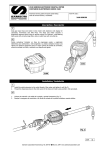
RFX Meter Handle
Parts and Technical Service guide
Guía de servicio técnico y recambio
Guide d’instructions et pièces de rechange
Ref.:
Model 2188
Description/ Descripción/ Description
E
The Samson RFX is designed to control and monitor the
consumption and inventory balances of automotive fluid products
with minimal installation and programming costs. The wall mounted
keypad module consists of a 12-button keypad, LCD display and
integral ticket printer. The RFX keypad can control up to 48 meters
and track 8 different fluids and tanks. It is capable of sending and
receiving data typically up to 300 feet in a service facility
installation. A unique, patented feature of the control system is that
the dispense trigger of the RFX Meter is locked until authorization
from the keypad is received. After the dispense is completed, the
user can top off the dispense and the actual amount used is sent
back to the keypad and this meter returns to the locked status.
Additionally, the meter can be installed on portable dolly systems
offering control and monitoring of often high-cost lubrication
products. Up to 50 operators can be defined with their own unique
PIN number for accessing the system. The system provides
dispense reports by operator, fluid type, meter or tank. This allows
for flexibility in reviewing system activity.
Operation/ Modo de empleo/ Mode d’emploi
E
The operator enters his PIN number and RO number and then selects the hose that the fluid is to be
dispensed from. The operator then enters the required quantity and presses ENTER to confirm. After preesing
‘Reset’ the meter is then authorized to automatically dispense and shut off when the authorized amount of
fluid is dispensed. The operator may then top off the vehicle for the proper fill, if necessary. The operator
may allow the meter to “time out” or may depress “Reset” which sends all actual dispense data back to the
keypad and puts the meter into a secure “Locked” status until the next authorized dispense work order is
received from the keypad. After each dispense, a transaction ticket is printed showing the fluid and quantity
dispensed along with the operator's name.
System Features
•
•
•
•
•
•
•
•
Very low installation costs
Patented “Lock-Out” to prevent unauthorized dispenses
Oval Gear metering technology
Measurement in Pints, Quarts, Gallons or Liters
Field replaceable AA Batteries in meters
Control of portable fluid tanks
Integral ticket printer
Serial port for report printer
2188
1
Samson Corporation-Swannanoa, NC 28778 800-311-1047 www.samsoncorporation.com
TABLE OF CONTENTS
Definitions ...................................................................... 3
Installation ................................................................... 4-5
Operating the Meter ....................................................... 5
Programming the Meter ................................................. 6
Operational Functions ................................................... 7
Service ........................................................................... 7
Dimensional Drawing .................................................. 10
Specifications ............................................................... 10
Parts Drawing ......................................................... 11-13
Troubleshooting ........................................................... 14
Factory Settings
Each meter is preprogrammed and calibrated at the factory.
Unless otherwise specified at the time of the order, each
meter is programmed in quarts for use with motor oil. The
meter is shipped in the Manual Mode. If you need to change
the factory settings, see page 6.
1000 psi (67 bar) Maximum Working Pressure
8 gpm (30 Lpm) Maximum Flow Rate
This Meter is designed specifically to dispense motor oils
(S.A.E. 5-50), gear oils (S.A.E. 80-240), automatic
transmission fluid, antifreeze (Ethylene Glycol) solution,
and hydraulic fluid. Other models of the EPM are designed
to dispense brake fluid or windshield wiper fluid.
SYMBOLS
12.Do NOT dispense valves towards any person or any
part of the body.
13.Do NOT place hands or fingers over the end of or into
the dispense valve.
14.Comply with all local, state, and federal fire, electrical,
and safety regulations
15. Use of this product in a manner other than specified
in this manual may result in impaired operation or
damage to equipment.
Meter Overview
FCC ID: GIF-RFEPM
FCC CERTIFIED, PART 15, SUBPART C
This device complies with Part 15 of the FCC Rules. Operation
is subject to the following two conditions: (1) this device may not
cause harmful interference, and (2) this device must accept any
interference received, including interference that may cause
undesired operation.
The meter is Samson's Electronic Preset meter (RFX)
equipped with RF communications allowing
authorization and dispense information. Once a work
order has been set up, the operator simply pulls the
trigger and the authorized amount of fluid for that meter
will dispense. The valve will automatically shut off when
the full amount has been dispensed. A “Top Off” feature
allows additional amounts to be dispensed and tracked
after the valve closes. Upon completion of the dispense
effort, the valve locks prohibiting any unauthorized
dispense to occur.
This symbol is an alert to the possibility of serious injury
or death if the instructions are not followed.
This symbol is an alert to the possibility of damage to or
destruction of equipment if the instructions are not followed.
Equipment Misuse Hazard
1. This equipment is for professional use only.
2. Read all instructions, tags, and labels before
operating the equipment.
3. Use the equipment only for its intended purpose.
4. Do NOT modify or alter the equipment.
5. Do NOT leave equipment unattended while
dispensing.
6. Check equipment daily. Repair or replace worn or
damaged parts immediately.
7. Do NOT exceed the maximum working pressure level
of the lowest rated system component.
8. Use only extensions and nozzles that are designed
for use with this equipment.
9. Use only fluids and solvents that are compatible with
the equipment. Read all fluid and solvent
manufacturer’s warnings.
10.Tighten all fluid connections before operating this
equipment.
11.Do NOT stop or deflect leaks with hands, body,
gloves, or rags.
Meter Display and Keypad
Keypad Buttons
Used to enter the quantity to be dispensed when RF
communications are not available.
Samson Corporation-Swannanoa, NC 28778 800-311-1047 www.samsoncorporation.com
4.
Total
Used to display the accumulated total of fluid, as well as
the resettable total during normal operating mode.
5.
Place the hose end in a waste container. Make sure
hose is secure so no fluid will leak during flushing.
Slowly open the dispense valve and allow enough oil
to pass through to ensure that the system is clean.
Close the valve and repeat for all dispense positions.
Auto
Used to enter and exit the Auto Mode when RF
communications are not available.
Note: If the system has multiple dispense positions, begin
at the position farthest from the pump, and move
towards the pump.
Reset
6.
Used to accept a dispense order from the keypad. Used
in normal operating mode (RF, manual or auto) to clear
the previously programmed batch and to reset the
meter. Used to reset the resettable total after pressing
the TOTAL button.
7.
Relieve the Pressure (see Relieve the System
Pressure, above).
Insert the metal end of the hose into the swivel
located at the end of the handle, and tighten
completely with an open ended, adjustable wrench.
Shut-Off
Used to stop the flow through an electrical override.
Meter Installation
Pre-Installation Procedure
1. Relieve the system pressure:
a. Turn off the power supply to the pump or close the
shutoff valve.
b. Dispense any fluid in the system into a waste
container by opening the dispense valve.
c. Open all bleed-type master air valves and fluid
drain valves in the system.
d. Leave the drain valve open until ready to
pressurize
the system.
Attaching the hose
Note: The threaded end of the meter will always have
female threads, so the metal end of the hose must
have male threads. Apply thread sealant to the male
end. The inlet and outlet connections are both 1/2"
NPT or 1/2" BSPP depending on meter model.
8.
2. Close the shutoff valve.
Thread the new nozzle onto the opposite end of the
meter and screw in tightly with an open ended,
adjustable wrench.
3. Ground hoses and reels:
Grounding reduces the risk of static sparking;
ground all system components according to local,
state, and federal code. Consult the user's manual
of the pump and other system components to
ground the following:
i. Pump: follow manufacturer's recommendations
ii. Air and Fluid Hoses: use only grounded hoses
iii. Air Compressor: follow manufacturers
recommendations
iv. Fluid Supply Container: Follow the local code
Installing the nozzle
9.
Do not use Teflon® tape on pipe joints; it may cause a
loss of grounding across the joint.
Installation Procedure
1. If this is an existing installation, go directly to step 6.
Steps 2 through 5 are for flushing the system prior to
installing the meter.
2. Close fluid dispense valves at every dispense position.
3. Once the main fluid outlet valve at the pump is
closed, the air pressure to the pump motor is
properly adjusted, and the air valve is open, slowly
open the main fluid valve.
Open all dispense position shut-off valves, and start
the pump to pressurize the system.
10. To ensure accuracy, purge all air from the fluid lines
and dispense valve before use.
Samson Corporation-Swannanoa, NC 28778 800-311-1047 www.samsoncorporation.com
Do NOT press
before topping off. The meter will
begin a new batch.
Normal Operating Mode Functions
Total
This option allows users to see the accumulated total as
well as the resettable total.
Auto Mode
2. The meter is now ready to be programmed. Change
the
batch size by pressing the
,
and
buttons.
a.
b.
c.
Pressing the 10 button will increase the
batching amount in increments of 10 units.
Pressing the 1 button will increase the
batching amount in increments of 1 unit.
Pressing the 0.1 button will increase the
batching amount in increments of 0.1 units.
button while in normal
Press and hold the
operating mode to see the accumulated total. Continue
holding and after three seconds the screen will change to
the resettable total, which displays the total fluid dispensed
since the resettable total was last set back to zero.
Press the
button while viewing the resettable total
to set the resettable total back to zero. Release the
button to return to the normal operating screen.
Note: The accumulated total cannot be reset, unless the
user changes from English units to metric units or from
metric to English units. (See Changing Factory Settings.)
L
RESET TOTAL
3. Pull the trigger to begin the flow. The valve will
automatically lock in place, even though the trigger will
fall back to the closed position. The flow will
automatically shut off when the desired batch size has
been dispensed.
NOTE: The meter will automatically shut off if the trigger
is pulled and the meter does not sense any flow. The
display will then begin to flash indicating the meter has
shut off. Press the
button to stop the display from
flashing.
Also, in case of an emergency or to interrupt a batch, the
meter is equipped with an electrical override. (See
Electrical Override.)
Total Function
Electrical Override
In case of an emergency or to interrupt a batch, the meter
is equipped with an electrical override. This option
automatically closes the valve in the meter, stopping the
flow immediately. The display will begin to flash because
the meter does not sense any flow. Batching can be
continued after an override, even if the meter is in the
middle of a programmed batch and the display continues
to flash.
Press the red
button to activate the electrical
override. This button can only be used when the valve is
open.
The valve will always lock in the maximum open position.
4. The user has the option to top off at the end of the batch.
To top off the tank, simply pull the trigger to begin the flow
and release when the desired amount has been
pumped.
5. Press the
button when finished to reset the
meter. It is now ready for the next batch.
Press the
button to cue up the next batch and stop
the display from flashing.
Service
Changing the Battery
When the batteries need to be changed, a progression of
warnings will appear on the screen.
1. First warning: the Low Battery Icon will appear in the
Samson Corporation-Swannanoa 800-311-1047 www.samsoncorporation.com
lower left corner of the display. This means that the
batteries are low and need to be changed within one
week after the icon first appeared.
.
After the screen flashes, it will display the scale factor and
units of measurement.
QT
.
QT
QT
+
-
2. Second warning: The AUTO function will shut off and
the auto icon will disappear. This means the battery
power is too low to run the auto function. The meter
can still run in manual mode.
3. Third Warning: The screen goes blank. This means
there is no power left. The display cannot be run.
However the meter will still allow fluid to pass through
when the valve is opened, but it will not measure flow.
• The battery compartment is located on the underside of
the trigger guard. Unscrew the two screws located under
the guard and remove the battery cover to expose the
batteries.
• Replace the old batteries. This meter takes 4 AA
alkaline batteries. Replace the cover and the screws
when finished. Note battery polarity markings inside
battery compartment cover.
Initial Programming Screen
Programming the Units
This meter comes with the option to choose 4 different
units of measure. Unless otherwise specified at the time
of the order, each meter is programmed in quarts for use
with motor oil. The ‘QT' will be flashing on initial start-up.
1. Toggle the four options (‘L’, ‘QT’, ‘GAL’, ‘PT’) by
pressing the
2.
When the desired option is on the screen, press the
button to advance. The units of measurement
icon will stop flashing and the first digit of the scale
factor will begin flashing.
Note: If the ‘L’ units have been selected, the decimal point
will begin to flash. The user now has the option to change
the decimal point to either a period or a comma. To do
this, press the
• Dispose of used batteries properly according to local
regulations.
button.
button. Press the
button to
advance to the scale factor screen.
NOTE: Changing the batteries will not affect any of the
programmed values, or totals.
Changing the units of measurement from metric to English
units, or from English to metric units will clear the
accumulated total, and resettable total.
Changing Factory Settings
Factory Settings
Each meter is preprogrammed and calibrated at the
factory. Unless otherwise specified at the time of the
order, each meter is programmed in quarts for use with
motor oil.
1.
Press
to wake up the meter if screen is blank.
To enter the programming mode, press and hold the
"PROGRAMMING" key located in the access hole
under the meter for 2 seconds. (See picture)
Recalibrating the Meter
The Scale factor is used to adjust the accuracy of the meter.
The scale factor will be set at the factory using oil with the
viscosity of 10W motor oil. The primary use for the
recalibration function is if the user wants to batch fluids with
a different viscosity. If the fluid has a lower viscosity, more
fluid can slip past the gears without being detected. Changing the scale factor can adjust the meter to compensate for
that loss. The meter multiplies each pulse by this number
to correct the accuracy when it converts to the specified
units, so the reading on the dial is always correct.
For an approximate scale factor for fluids of different
viscosities, consult the following chart:
Use a 5/32"
Allen wrench
or similar
blunt tool
Location of access hole for PROGRAMMING Key.
Type of Fluid
Viscosity (cSt)
Water/Anti-Freeze
5
Anti-Freeze
18
Automatic Transmission Fluid
80
Motor Oil
140
Mobil 80W-90
450
50W
900
140W
1800
Scale Factor
1.044
1.007
1.002
1.000
0.999
0.996
0.993
(Unless otherwise specified at the time of the order, each
meter is programmed in quarts for use with 10W motor oil.)
Samson Corporation-Swannanoa, NC 28778 800-311-1047 www.samsoncorporation.com
Note: The original meter scale factor is written inside of
the meter when calibrated at the factory. It may have been
revised after field installation. Use scale factor shown on
display, not the trigger.
To view the current program scale factor, do the following:
1. Press and hold the
button.
Pulse Delay Screen
2. Then, press and hold the
button.
For an absolute scale factor, perform the following test:
Run a measured amount of fluid through the meter. If the
meter delivers 4.20 quarts, and the display shows only 4.00
quarts, then the scale factor needs to be adjusted. Divide
what the meter delivered (4.20) by what the display shows
(4.00) to get the error factor (1.05).
Advance through the unit selection and all five scale factor
digits by pressing the
button. The above screen will
now be displayed.
1. The 'PS-' will be followed by a flashing zero. The zero is
the initial setting of the pulse delay factor
Calculating the new scale factor:
2. Scroll between settings (0 to 5) by pressing the
If existing scale factor is 1.0123, then the calculation would
be: 1.0123 (existing scale factor) x 1.05 (error factor) =
1.0629 (new scale factor).
Change the scale factor:
3. When finished selecting the pulse delay factor, press
and the display will return to the scale factor
Press "PROGRAMMING" key to enter the programming
mode, and the
button.
button to advance through the units
mode.
screen.
4. When finished programming these options, press the
"PROGRAMMING" key and hold it until the screen
flashes three times then goes blank. Press the
1. The first digit of the scale factor will be flashing.
button to scroll through the numbers.
2. Press the
,
button to return to the normal operating screen.
L
Scale Factor Screen
3. Press
to advance to the next number in the scale
factor.
4. Repeat steps 2 and 3 for all five digits in the scale factor.
Note: All digits can be scrolled between 0 and 9 except
the first, which can only be scrolled from 0 to 1.
5. When finished setting the scale factor, press the
button and the scale factor and units measurement
screen will be replaced with the pulse delay screen:
Setting the Pulse Delay Factor
The Pulse Delay Factor is used to correct for fast flow
rates by closing the valve in the meter between one and
five pulses sooner than the selected value. The meter is
factory programmed with a pulse delay factor of 0.
800-311-1047 www.samsoncorporation.com
11.0"
3.8"
7.0"
SPECIFICATIONS
English
Metric
Maximum Flow *
8 gpm
30 lpm
Minimum Flow *
0.25 gpm
1 lpm
Operating Pressure (Maximum)
1000 psi
67 bar
Operating Pressure (Minimum)
5 psi
.35 bar
Operating Temperature (Maximum)
120° F
50° C
Operating Temperature (Minimum)
20° F
- 5° C
Accuracy - Oils
+/- 0.5%
+/- 0.5%
Accuracy - Anti-freeze
+/- 1.5%
+/- 1.5%
5-Digit LCD Display, 10 mm High x 5 mm Wide
Quarts, Pints, Gallons
Liters
Inlet and Outlet Connections
½” NPT
½” BSPP
* Tested with DTE-25 motor oil at ambient temperature. Min.-Max. flow range will vary with fluid viscosity.
Samson Corporation-Swannanoa, NC 28778 800-311-1047 www.samsoncorporation.com
Samson Corporation-Swannanoa, NC 28778 800-311-1047 www.samsoncorporation.com
Samson Corporation-Swannanoa, NC 28778 800-311-1047 www.samsoncorporation.com
Samson Corporation-Swannanoa, NC 28778 800-311-1047 www.samsoncorporation.com
Distributed by:
Samson Corporation-Swannanoa, NC 28778 800-311-1047 www.samsoncorporation.com