1
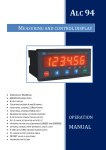
ALP 94-‐UNı MEASUREMENT INSTRUMENTS 0 – 20 mA ANALOGUE INPUT 4 – 20 MA ANALOGUE INPUT 0 – 10 V ANALOGUE INPUT POTENTIOMETRIC ıNPUT USER MANUAL INDEX 1. TECHNICAL PROPERTIES…….………………..………………………………………………………………………………….. 2 2. CONNECTIONS.…………….………………..……………………………………………………………………………………….. 3 3. DESCRIPTION OF FRONT PANEL.….………………………………………………………………………………………….. 6 3.1. Displaying Minimum and Maximum Values.…………..………………………..……………….…………. 6 4. INSTRUMENT SETTINGS..…………………………………………………………………………………………………………. 7 4.1. Input Menu………………………………..…………………………………………………………………………………. 8 4.1.1. Sensor Type Selection (sensor)…..…………………………………………………………………………… 8 4.1.2. Entering Set Value While Password Protection is Active (left).……….………………………. 9 4.1.3. Tare Mode Selection (tare)…………………………………………………………………………………….. 10 4.2. Output Menu………………………………………………………………..……………………………………………… 11 4.2.1. Entering Set Value (set)………………………………………………………………………………………….. 11 4.2.2. Setting Hysteresis (hys)……………..………………………………………………………………………….. 12 4.2.3. Relay Output Mode (type)…………………………………….……………………………………………….. 13 4.2.4. Setting Relay Output Time (t-‐out)……………………….………….………………………………………. 14 4.2.5. Setting of Decimal Point (decpnt)……………………….………………………………………………….. 15 4.2.6. Display Refresh Rate (rate)……………………………….……………..…………………………………….. 15 4.3. Calibration Menu………………………………………………….……………………..………………………………. 16 4.3.1. Setting of Scale Limit Values (SCL-‐Lo / SCL-‐HI)..……………………………..………………………. 16 4.3.2. Manual Calibration (CAL-‐Lo / CAL-‐HI)…………….………………………………………………………. 17 4.3.3. Automatic Calibration (autoCL)………………………………………………….…………………………… 18 4.3.4. Setting of Offset Value (offset)………….……………………………………..……………………………. 18 4.3.5. Setting of Screen Filter (filter)…………..………………………………………….………………………… 19 4.4. Security Menu………………………………………………………………………………………………………………. 20 4.4.1. Setting Password Protection (protec, pass)……………………………………………………………. 20 4.4.2. Return to Factory Defaults (fac. def.)……………………………………………………………………… 21 5. DATA PROTOCOL……………………………………………………………….…………………………………….………………. 22 6. ERROR MESSAGES……………………………………………………..……………………………………………….……………. 22 7. CERTIFICATE of WARRANTY.………………………………………..…………………………………………………………… 23 8. QUICK CALIBRATION GUIDES……………………………………………………………………………………………………. 24 8.1. QUICK POTENTIOMETER CALIBRATION GUIDE………………………………………………………………. 24 8.2. QUICK 0-‐10V OUTPUT SENSOR CALIBRATION GUIDE…………………………………………………….. 25 8.3. QUICK 2-‐WIRE 4-‐20mA OUTPUT SENSOR CALIBRATION GUIDE……………………………………… 26 8.4. QUICK 3-‐WIRE 4-‐20mA OUTPUT SENSOR CALIBRATION GUIDE……………………………………… 27 8.5. QUICK 0-‐20mA OUTPUT SENSOR CALIBRATION GUIDE………………………………………………….. 28 [1] 1. TECHNICAL PROPERTIES ELECTRICAL CHARACTERISTICS 24 VAC/DC 50/60 Hz or 85-‐265 VAC 50/60 Hz SUPPLY VOLTAGE POWER CONSUMPTION 7 VA / 5.6 W Max SENSOR SUPPLY VOLTAGE 24 VDC 50 mA CONNECTION 2,5 mm² screw-‐clemens Potentiometer 0-‐10 V 4 – 20 mA 0 – 20 mA 0 – 10 V (Optional) 4 – 20 mA (Optional) INPUTs (Analogue) OUTPUTs (Analogue) OUTPUTs (Relay) 3 relays (Optional 4 relays): 250 VAC 3A (For Resistive Load) Relay Serial Communication RS-‐232 (Optional) PHYSICAL CHARACTERISTICS DIMENSIONS 96 x 48 x 88 mm WEIGHT 300 gr. MOUNTING Upper and lower legs are fixed to the panel. RELATIVE HUMIDITY @31 °C up to 80%, @40 °C up to 50% STORAGE TEMPERATURE -‐10°C……60 °C OPERATING TEMPERATURE 0°C……50 °C PROTECTION CLASS IP 60 Front Panel, IP 20 Back panel DIMENSIONS 96 mm 48 mm 46 mm 94mm [2] 2. CONNECTIONS 3. These inputs are optional. 4..20 mA Output + -‐ + + 0..10 V Output GND GND +24 Vdc 0..10 V Input These terminals are open, if it’s not specified in the order. 4..20 / 0..20 mA Input Tare -‐ + + OUT 2 NC NC NO OUT 1 NO COM COM NC NO COM + -‐ -‐ N Supply Voltage L 24 VAC / DC or 85 / 265 VAC OUT 3 SAFETY WARNINGS 1. Please follow the instructions and warnings in the user manual. 2. Please check the type of power supply before connecting the instrument to power. 3. Please mount the instrument on the panel firmly, against dangers of falling, slipping and vibration during operation. 4. Please connect the sensors to the instrument while the instrument is powered OFF. Do not connect sensors to the instrument during operation. 5. Please use shielded cables to connect the sensors to the instrument, and please make sure there are no high current power cables near sensor connection cables. 6. Please do not leave the device exposed to a heat source (solar, heater etc.) 7. ALP94 industrial control device is not suitable for outdoor use. Please use the instrument only in indoor conditions. 8. Please clean the instrument with a wet towel. Please do not use water directly, or thinner etc. 9. Please comply with the limit values of relay outputs, specified in the technical properties. 10. Please do not try to repair the instrument in the event of failure. Please contact our technical service in case of failure. [3] [4] [5] 3. DESCRIPTION OF FRONT PANEL ALP94 instrument operates in 2 different modes: Operating Mode : Sensor reading is shown on the display Programming Mode : Instrument Settings are programmed. Button Functions 1. 2. 3. 4. PROG Button Programming Mode: Enter the menu / Save the parameter value. ESC Button Programming Mode: Exit without saving the parameter value. LEFT Button Programming Mode: Change the decimal place of the parameter value. DOWN Button Programming Mode: Scroll down the menu / Decrease the parameter value. Operating Mode: Display MIN/MAX values. 5. UP Button Programming Mode: Scroll up the menu / Increase the parameter value. Operating Mode: Tare Button, if Tare function is programmed. Status LEDs 6. TARE 7. ABSOLUTE/RELATIVE 8. MIN 9. MAX 10. OUT1 11. OUT2 12. OUT3 : ON if Tare function is active. : ON if Offset value is entered. : ON if DOWN button is pressed once, and the display shows MIN value. : ON if DOWN button is pressed twice, and the display shows MAX value. : ON if the relay at OUT-‐1 is switched. : ON if the relay at OUT-‐2 is switched. : ON if the relay at OUT-‐3 is switched. 3.1. Displaying Minimum and Maximum Values to see Minimum(MIN) value, press DOWN ( ) button once, during operation. Minimum value In order will be shown in the display, and MIN status LED will be ON. In order to see Maximum(MAX) value, press DOWN ( ) button again, while Minimum value is shown in the display. Maximum value will be shown in the display. MAX status LED will be ON, and MIN status LED will be OFF. In order to reset MIN or MAX value, press to ESC ( ) button, while the value is shown in the display. In order to return to sensor reading display, press DOWN ( ) button, while MAX value is shown in the display. MAX status LED will be OFF, and sensor reading will be shown in the display. [6] 4. INSTRUMENT SETTINGS Entrance to Programming Mode and Setting Menu: If you press and hold PROG ( ) button, while the instrument is in Operating Mode, then the display will show “prog”. If you press UP ( ) button, while you hold PROG ( ) button, the instrument will enter Programming Mode and the Setting Menu, and the display will show “INPUT", first item of the Setting Menu. prog ˝Input If password protection is active, then the display will show “pass” after “PROG”, and the instrument will ask for password before entering Programming Mode. Password can be entered by adjusting the parameter value on the display with UP ( ), DOWN ( ), and LEFT ( ) buttons. After adjusting parameter value on the display, press PROG ( ) button to enter the password. If the password is correct, then the instrument will be in Programming Mode, and the display will show “true” message, and afterwards “INPUT”, first item of Setting Menu. If the password is incorrect, then the display will show “FALSE”. The instrument will still enter the Setting Menu, but the user won’t be able to make any changes. Setting Menu will be read-‐only. prog ˝pass If password is correct: If password is incorrect: 0 true ›Input faLse ›Input There are 4 submenus in the Setting Menu: INPvT : Input sensor settings OvTPvT : Relay output settings CALIB : Calibration and sensor limit settings SECURE : Security settings You can switch between submenus in the Setting Menu with UP ( ) and DOWN ( ) buttons, and enter the submenu with PRG ( ) button. Once you enter a submenu, you’ll see the parameters related to that submenu. You can switch between parameters in the submenus with UP ( ) and DOWN ( ) buttons. If you want to change a parameter, press PRG ( ) button, while the name of the parameter is in the display. Adjust the parameter value with UP ( ), DOWN ( ) and LEFT ( ) buttons, and save it by pressing PRG ( ) button. If you want to exit without saving the parameter value, press ESC ( ) button while adjusting the parameter, and you’ll return to the related submenu. Setting Menu prog ˝Inpvt ˝Ovtpvt [7] ˝CaLIb ˝seCvre 4.1. INPUT MENU Input Menu prog ˝Inpvt sensor Left tare 4.1.1. Sensor Type Selection (sensor) Sensor type is selected through this parameter. There are 4 different types of sensor, which ALP94 can interact with; Linear Potentiometer, 0-‐10V output sensor, 4-‐20mA output sensor and 0-‐20mA output sensor. Please check Connection Section (pages 3-‐5) for sensor connections of these output types, and please connect the sensor while the instrument is powered OFF. In order to reach this parameter, enter Setting Menu by pressing PRG ( ) and UP ( ) buttons. First submenu in the Setting Menu is Input Menu, so the display will show “INPUT”. Press PRG ( ) button to enter Input Menu. First parameter in the Input Menu is “SENSOR”. Press PRG ( ) button in order to see the current setting for “SENSOR” parameter. Press PRG ( ) button again in order to adjust the parameter; the display will start to flash. While the display is flashing, use UP ( ) and DOWN ( ) buttons to switch between sensor types. Press PRG ( ) button to save the parameter. If you want to exit without saving the parameter, press ESC ( ) button and the instrument will return to its previous state. prog ˝Inpvt sensor Sensor Types LInpot 0-10U [8] 4-20na 0-20na 4.1.2. Entering Set Value While Password Protection is Active (left) Set Values for output relays are entered through Output Menu in Programming Mode (see 4.2.1 Entering Set Value p. 11). If password protection for Programming Mode is active (see 4.4.1 Setting Password Protection p. 20), the user cannot change Set Values without knowing the password. Left Function allows the user to enter Set Values directly while the instrument is working in Operating Mode, without entering Programming Mode. Therefore, Set Values can be entered with Left Menu, while the password protection for Programming Mode is active. In order to activate Left Function, enter Setting Menu by pressing PRG ( ) and UP ( ) buttons. First submenu in the Setting Menu is Input Menu, so the display will show “INPUT”. Press PRG ( ) button to enter Input Menu. First parameter in the Input Menu is “SENSOR”. Press UP ( ) button, and the display will show “Left”. Press PRG ( ) button to enter Left Function settings. The display will show the current setting for Left Function. In order to change the setting for Left Function, press PRG ( ) button again, and the display will start flashing. Use UP ( ) and DOWN ( ) buttons to in order to change the setting, and PRG ( ) button to save the setting. If display shows “On”, Left Function is active. If the display shows “OFF”, Left function is disabled. If you want to exit without saving the setting, press ESC ( ) button while the display is flashing. prog Left Function Settings On [9] sensor ˝Inpvt Off Left 4.1.3. Tare Mode Selection (tare) Tare function resets the zero point of the scale display. For example, 100mm linear potentiometer is connected to the instrument, and the display shows “0” at 0mm, and “100” at 100mm. Tare function can make the display show “0” at 10mm and “90” at 100mm, if it is desired. In order to select Tare Mode, enter Setting Menu by pressing PRG ( ) and UP ( ) button. First submenu in the Setting Menu is Input Menu, so the display will show “INPUT”. Press PRG ( ) button to enter Input Menu. Tare Mode Selection parameter is the third parameter in Input Menu, so press DOWN ( ) button once, and the display will show “tARE”. Press PRG ( ) button once, in order to see the current Tare Mode selection. Press PRG ( ) button again to change the Tare Mode, and the display will start flashing. Select one of the four Tare Modes, by using UP ( ) and DOWN ( ) buttons, then press PRG ( ) button again to save the change. If you want to exit without saving, press ESC ( ) button while the display is flashing. Four different Tare Mode functions and their descriptions: 1. Cn-ofs : Every time TARE ( ) button is pressed; the value on the display will be equal to offset value. (See 4.3.4 Setting of Offset Value p. 18) TARE status LED will be ON. 2. Cn-zer : Every time TARE ( ) button is pressed, the value on the display will be equal to zero. TARE Status LED will be ON. 3. aR-ofs : If TARE ( ) button is pressed, the value on the display will be equal to offset value (See 4.3.4 Setting of Offset Value p. 18). TARE status LED will be ON. If TARE ( ) button is pressed again, then Tare function will be disabled, and the display will work as if Tare function is inactive. TARE status LED will be OFF. 4. ar-zer : If TARE ( ) button is pressed, the value on the display will be equal to zero. TARE status LED will be ON. If TARE ( ) button is pressed again, then Tare function will be disabled, and the display will work as if Tare function is inactive. TARE status LED will be OFF. 5. Off : Tare function is disabled. TARE status LED will be OFF. prog sensor ˝Inpvt Tare Modes Off ar-zer aR-ofs Cn-zer Cn-ofs [10] tare 4.2. OUTPUT MENU Output Menu prog ˝Inpvt ˝Ovtpvt Output Menu set-1 set-2 set-3 Hys-vp Hys-dn Type-1 Type-2 Type-3 T-ovt1 t-ovt2 t-ovt3 decpnt rate 4.2.1. Entering Set Value (set) There are three output relays in ALP-‐94 (optionally 4 relays). Each output relay has a Set Value parameter. So there are three Set Value parameters, namely “Set-1”, “Set-2” and “Set-3”. Output relays are numbered according to the connection diagram on page 3. “Set-1” is the Set Value of the relay at OUT-‐1. “Set-2” is the Set Value of the relay at OUT-‐2, and “Set-3” is the Set Value of the relay at OUT-‐3. If the value on the display is equal to a Set Value, the corresponding relay switches and corresponding status LED will be ON. In order to enter Set Values, you should first enter to Setting Menu by pressing PRG ( ) and UP ( ) buttons. First submenu in the Setting Menu is Input Menu, so the display will show “INPUT”. Output Menu is the second submenu in Setting Menu, so press UP ( ) button, and the display will show “Ovtpvt”. Press PRG ( ) button to enter Output Menu, and the display will show “SET-1”. First three items in the Output Menu are “SET-1”, “SET-2”, and “SET-3”. Scroll up or down to the Set Value you want to enter, by using UP ( ) and DOWN ( ) buttons. Then press PRG ( ) button in order to enter the Set Value parameter. The display will show the current Set Value parameter. In order to change it press PRG ( ) button again, and the rightmost digit will start flashing. While the rightmost digit is flashing, use UP ( ) and DOWN ( ) buttons to increase or decrease that digit. Press LEFT ( ) button to change the next digit. Once you entered the value you want for that Set Value, press PRG ( ) button to save it. If you want to exit without saving, press ESC ( ) button. Output Menu prog ˝Inpvt ˝Ovtpvt set-1 set-2 set-3 ... Use UP and DOWN buttons to increase the flashing digit, and use LEFT button to go to next digit. Set Value Parameter 10 [11] 4.2.2. Setting Hysteresis (hys) Hysteresis can be used to prevent rapid unwanted relay switching. If there is no Hysteresis, then output relays will switch at their corresponding Set Value. If there is noise in the sensor signal, or vibration in the sensor, so that the value on the display is going higher and lower than Set Value very frequently, the relay will rapidly switch many times. In order to prevent this, Hysteresis can be set up. There are two Hysteresis functions: “Hys-vP” (Hysteresis-‐Up) which adds Hysteresis for upward motion, and “Hys-dn” (Hysteresis-‐ Down) which adds Hysteresis for downward motion. Upward motion is, when the display is going from a low value up to a high value. Downward motion is, when the display is going from a high value down to a low value. For example, if “SET-1” parameter is equal to “10”, and “HYS-vP” is equal to “2”, and “HYS-dn” is equal to zero, then OUT-‐1 relay will switch at “12” for upward motion, and it will switch at “10” for downward motion. Similarly, if “SET-1” parameter is equal to “10”, and “HYS-vP” is equal to zero, and “HYS-dn” is equal to “2”, then OUT-‐1 relay will switch at “10” for upward motion, and it will switch at “12” for downward motion. Once a Hysteresis parameter is set, it will affect all the relay outputs. In order to set Hysteresis, you should first enter to Setting Menu by pressing PRG ( ) and UP ( ) buttons. The display will show the first submenu in Setting Menu, “INPvT”. Output Menu is the second submenu in Setting Menu, so press UP ( ) button, and the display will show “Ovtpvt”. Press PRG ( ) button to enter Output Menu. “HYS-vP” and “HYS-dn” are fourth and fifth items in the Output Menu, so press UP ( ) button 3 times to reach “HYS-vP”, and press UP ( ) button once more to reach “HYSdn”. Press PRG ( ) button to see the current setting for Hysteresis. In order to change the Hysteresis values, press PRG ( ) button again, and the rightmost digit will start flashing. While the rightmost digit is flashing, use UP ( ) and DOWN ( ) buttons to increase or decrease that digit. Press LEFT ( ) button to go to the next digit. Once you entered the value you want for that Hysteresis, press PRG ( ) button to save it. If you want to exit without saving, press ESC ( ) button. Output Menu prog ˝Inpvt ˝Ovtpvt x3 Use UP and DOWN buttons to increase the flashing digit, and use LEFT button to go to next digit. Hysteresis Parameter 2 [12] ... Hys-vp Hys-dn ... 4.2.3. Relay Output Mode (type) Relay Output Modes define how the relay outputs will work. There are four different Relay Output Modes: “Hys”, “band”, “dose” and “pLvraL”. “HYS” is the default Mode for all relay outputs. In this Mode, Hysteresis is active (see 4.2.2 Setting Hysteresis p. 12), and relays will switch at their corresponding Set Values plus Hysteresis values. “band” Mode defines a bandwidth where the relay will be switched. Outside that bandwidth the relay output will be in its default position. When “band” Mode is selected, corresponding Set Value Menu will ask you two parameters to define the bandwidth, a lower and an upper limit. For example, if you define “type-1” as “band”, then the relay at OUT-‐1 will be in “band” Mode. Therefore “SET-1“ menu will ask you to enter “fron-1”(lower limit) and “to-1”(upper limit) parameters. The relay at OUT-‐1 will be switched between “Fron-1” up until “to-1” value. Outside that range, the relay will be in its default position. “dose” Mode will change the output of the relay at the multiples of the corresponding Set Value. For example if you define “type-2” as “dose”, the relay at OUT-‐2 will be in “dose” Mode. If you enter “SET2” as “5”, the relay at OUT-‐2 will switch at 5, 10, 15, 20…. The relay will stay switched for the time period defined in “t-Ovt2” (see 4.2.4 Setting Relay Output Time p. 14). “pLvraL” is only available for “type-1”, so you can use this Mode only for relay at OUT-‐1. You can define 10 different Set Values for OUT-‐1 relay. The relay will switch when the value on the display reaches to one of the defined Set Values for the time period defined in “t-Ovt1” (see 4.2.4 Setting Relay Output Time p. 14). In order to select Relay Output Modes, you should first enter to Setting Menu by pressing PRG ( ) and UP ( ) buttons. The display will show the first submenu in Setting Menu, “INPvT”. Output Menu is the second submenu in Setting Menu, so press UP ( ) button, and the display will show “Ovtpvt”. Press PRG ( ) button to enter Output Menu. Relay Output Modes are selected for each relay separately through “type-1”, “type-2” and “type-3” parameters, which are sixth, seventh and eighth in the Output Menu. Press UP ( ) button 5 times to reach the sixth parameter in Output Menu, which is “type-1”. Press PRG ( ) button to see the current setting of the Relay Output Mode for OUT-‐1 relay. In order to change the Mode, press PRG ( ) button again, and the display will start flashing. Use UP ( ) and DOWN ( ) buttons to navigate inside the menu, and press PRG ( ) button to save the Mode. If you want to exit without saving, press ESC ( ) button. Output Menu prog ˝Ovtpvt ˝Inpvt x5 Relay Output Modes Hys band dose [13] pLvral ... Type-1 Type-2 Type-3 ... 4.2.4. Setting Relay Output Time (t-‐out) Relay Output Time defines how long a relay will stay switched, after the value on display reaches the corresponding Set Value. For example, if you make “t-Ovt1” equal to “1.00” second, OUT-‐1 relay will be switched for 1 second upon reaching its Set Value. After 1 second, OUT-‐1 relay will be in its default state. Relay Output Time is set for each relay separately through “t-Ovt1”, “t-Ovt2” and “t-Ovt3” parameters, and they are all equal to zero by default. In order to set Relay Output Time, you should enter to Setting Menu by pressing PRG ( ) and UP ( ) buttons. The display will show the first submenu in Setting Menu, “INPvT”. Output Menu is the second submenu in Setting Menu, so press UP ( ) button, and the display will show “Ovtpvt”. Press PRG ( ) button to enter Output Menu. Press DOWN ( ) button 5 times to reach “t-Ovt1”. Press PRG ( ) button to see the current setting for Relay Output Time of OUT-‐1 relay. The display will show a number with two decimal places, like “0.00”. The unit for Relay Output Time parameter is seconds, so “1.00” is equal to 1 seconds. Press PRG ( ) button again to change the parameter. The rightmost digit will start flashing. While the rightmost digit is flashing, use UP ( ) and DOWN ( ) buttons to increase or decrease that digit. Press LEFT ( ) button to go to the next digit. Once you entered the value you want for that Relay Output Time, press PRG ( ) button to save it. If you want to exit without saving, press ESC ( ) button. Output Menu prog ˝Inpvt ˝Ovtpvt x5 Use UP and DOWN buttons to increase the flashing and use LEFT button digit, to go to next digit. Relay Output Modes 0.00 [14] ... T-Ovt1 T-Ovt2 T-Ovt3 ... 4.2.5. Setting of Decimal Point (decpnt) The position of the decimal point can be adjusted through this menu. There are 6 digits in the ALP94’s display, so there are 5 options for decimal point position. In order to set Decimal Point Position, you should first enter to Setting Menu by pressing PRG ( ) and UP ( ) buttons. The display will show the first submenu in Setting Menu, “INPvT”. Output Menu is the second submenu in Setting Menu, so press UP ( ) button, and the display will show “Ovtpvt”. Press PRG ( ) button to enter Output Menu. Press DOWN ( ) button 2 times to reach “deCpnt”. Press PRG ( ) button to see the current setting for Decimal Point Position. Press PRG ( ) button again to change the position of the decimal point. The decimal point will start flashing. While the decimal point is flashing use UP ( ) and DOWN ( ) buttons to change the position of the decimal point. Press PRG ( ) button again to save the setting. If you want to exit without saving, press ESC ( ) button. Output Menu prog ˝Inpvt ˝Ovtpvt x2 ... dECpnt ... Position of Decimal Point 0.000 4.2.6. Display Refresh Rate (rate) Display Refresh Rate determines how frequently the value on the display will refresh. There are three options for Display Refresh Rate: “nornaL”(normal), “sLoU”(slow), “fast”(fast). This setting won’t change the sampling rate of the instrument. In order to set Display Refresh Rate, you should enter to Setting Menu by pressing PRG ( ) and UP ( ) buttons. The display will show the first submenu in Setting Menu, “INPvT”. Output Menu is the second submenu in Setting Menu, so press UP ( ) button, and the display will show “Ovtpvt”. Press PRG ( ) button to enter Output Menu. Press DOWN ( ) button, and the display will show “rate”. When you press PRG ( ) button, the display will show the current setting for Display Refresh Rate. The display will also be flashing, so you can change the setting by using UP ( ) and DOWN ( ) buttons. In order to save the setting press PRG ( ) button. If you want to exit without saving, press ESC ( ) button. Output Menu prog ˝Inpvt Display Refresh Rate nornaL [15] ... rate ˝Ovtpvt sLoU fast 4.3. CALIBRATION MENU prog ˝Inpvt ˝CaLIb x2 Calibration Menu SCL-Lo SCL-HI CAL-Lo CAL-HI avtoCL Offset FILteR 4.3.1. Setting of Scale Limit Values (SCL-‐Lo / SCL-‐HI) Scale Limit Values determines what the display will show at the limits of the input sensor. For example, you connect a 4-‐20mA pressure transmitter to ALP94. You set the “SCL-Lo”(Scale-‐Low) parameter to “0” and “SCL-‐HI”(Scale-‐High) parameter to “100”. Then the display will show “0” at 4mA input, “50” at 12mA input, and “100” at 20mA input. Scale Limit Values can be used with all four types of sensors: 4-‐20mA, 0-‐20mA, 0-‐ 10V and potentiometer (see 4.1.1 Sensor Type Selection p. 8). For 4-‐20mA, 0-‐20mA and 0-‐10V type sensors, Scale Limit Values correspond to sensor limits. For potentiometers, Scale Limit Values must be adjusted with manual calibration (see QUICK POTENTIOMETER CALIBRATION GUIDE, p. 24). In order to set Scale Limit Values, you should enter to Setting Menu by pressing PRG ( ) and UP ( ) buttons. The display will show the first submenu in Setting Menu, “INPvT”. Press UP ( ) button twice, and the display will show “CaLIb”. Press PRG ( ) button to enter Calibration Menu. “SCL-Lo” and “SCL-HI” are the first parameters in the Calibration Menu. Press PRG ( ) button to see the current setting for “SCL-Lo”. In order to change the setting, press PRG ( ) button again. The rightmost digit will start flashing. While the rightmost digit is flashing, use UP ( ) and DOWN ( ) buttons to increase or decrease that digit. Press LEFT ( ) button to go to the next digit. Once you entered the value you want for “SCL-Lo”, press PRG ( ) button to save it. If you want to exit without saving, press ESC ( ) button. You can follow the same procedure for setting “SCL-HI”. Calibration Menu prog ˝Inpvt ˝CaLIb x2 Use UP and DOWN buttons to increase the flashing digit, and use LEFT button to go to next digit. Scale Limit Value 0 [16] SCL-Lo SCL-HI ... 4.3.2. Manual Calibration (CAL-‐Lo /CAL-‐HI) Manual Calibration menu is for sensors, which require calibration, like potentiometers. Manual Calibration allows you to define manually where the lower limit of sensor “CAL-Lo” and the higher limit of the sensor “CAL-HI” are. The display shows the “SCL-Lo” value at the manually defined “CAL-Lo”, and it shows “SCL-HI” value at manually defined “CAL-HI” (see 4.3.1 Setting of Scale Limit Values, p. 16). For example, you have a 100mm linear potentiometer. You define “SCL-Lo” value as “0”, and “SCL-HI” value as “100”. Then you set “CAL-Lo” where the potentiometer is at 0mm, and you set “CAL-HI” where potentiometer is at 100mm. Then the display will show “0” at 0mm, “50” at 50mm, and “100” at 100mm. You can use Automatic Calibration for 4-‐20mA, 0-‐20mA and 0-‐10V sensor types (see 4.3.3 Automatic Calibration, p. 18). However, the most accurate measurement can only be achieved with Manual Calibration. This is because all the sensors have an initial error, which can be eliminated with Manual Calibration. For example, you have a 10 bar pressure transmitter with 4-‐20mA output. Ideally, the sensor’s output will be 4.00mA at 0bar, and 20.00mA at 10bar. However, in practical world, the sensor’s output can be 3.98mA at 0bar and 20.01mA at 10bar. Automatic Calibration assumes that the sensor is ideal; therefore this difference will be an error. If you manually calibrate this sensor at 3.98mA and at 20.01mA, then this initial error will be eliminated. Please see (POTENTIOMETER CALIBRATION, p. 24) for instructions of manual calibration of potentiometers. For other types of sensors’ Manual Calibration procedure, you should first enter to Setting Menu by pressing PRG ( ) and UP ( ) buttons. The display will show the first submenu in Setting Menu, “INPvT”. Press UP ( ) button twice, and the display will show “CaLIb”. Press PRG ( ) button to enter Calibration Menu. Press UP ( ) button twice and the display will show “CAL-Lo”. Press PRG ( ) button to set the lower limit of manual calibration. The display will show a flashing “SET”. Adjust your sensor, so that the sensor’s output is at the lower limit. Press PRG ( ) button, when your sensor is at lower limit, and while the display is flashing “SET”. This point will be saved as the lower limit of the sensor. After that, the display will show “CAL-HI”. Press PRG ( ) button, and the display will again show a flashing “SET”. Now adjust your sensor, so that the sensor’s output is at the higher limit. Press PRG ( ) button, when your sensor is at the higher limit, and while the display is flashing “SET”. This point will be saved as the higher limit of the sensor. If you want to exit without saving, press ESC ( ) button. Calibration Menu prog ˝Inpvt ˝CaLIb x2 Manual Calibration Setting x2 SET Use PRG button to save the setting. Display will be flashing. [17] ... CAL-Lo CAL-HI ... 4.3.3. Automatic Calibration (autoCL) Automatic Calibration “Avto-CL” is for 4-‐20mA, 0-‐20mA and 0-‐10V type sensors. Since these sensors have already calibrated outputs, there is no need for manual calibration. When Automatic Calibration is ON, Manual Calibration will be disabled. Therefore, you won’t see the Manual Calibration parameters “CALLo” and “CAL-HI” in the Calibration Menu. Automatic Calibration allows you to use 4-‐20mA, 0-‐20mA and 0-‐10V sensors quickly without any calibration procedure. However, the most accurate measurement can only be achieved with Manual Calibration (see 4.3.2 Manual Calibration, p. 17, paragraph 2). In order to activate Automatic Calibration, you should first enter to Setting Menu by pressing PRG ( ) and UP ( ) buttons. The display will show the first submenu in Setting Menu, “INPvT”. Press UP ( ) button twice, and the display will show “CaLIb”. Press PRG ( ) button to enter Calibration Menu. Press UP ( ) button four times and the display will show “AvtoCL”. Press PRG ( ) button to see the current setting for “AvtoCL” parameter. The display will be flashing the current setting. In order to change the setting use UP ( ) or DOWN ( ) buttons, and press PRG ( ) button to save the setting. If you want to exit without saving, press ESC ( ) button. Calibration Menu prog ˝CaLIb ˝Inpvt x4 x2 ... AvtoCL ... Automatic Calibration On Off 4.3.4. Setting of Offset Value (offset) Offset value is used only for two Tare Modes, “Cn-oFS” and “AR-oFS” (see 4.1.3 Tare Mode Selection p. 10). While these Tare Modes are being used, pressing UP ( ) button, will match the current sensor input to this offset value. So the display will always show this offset value at that sensor input. In order to set Offset Value, you should first enter to Setting Menu by pressing PRG ( ) and UP ( ) buttons. The display will show the first submenu in Setting Menu, “INPvT”. Press UP ( ) button twice, and the display will show “CaLIb”. Press PRG ( ) button to enter Calibration Menu. Press DOWN ( ) button twice and the display will show “OFFSET”. Press PRG ( ) button to see the current setting for “OFFSET”, and press PRG ( ) button again to change the setting. The rightmost digit will start flashing. Use UP ( ), DOWN ( ), and LEFT ( ) buttons to enter the value you desire. Press PRG ( ) button to save the setting. If you want to exit without saving, use ESC ( ) button. Calibration Menu prog x2 x2 ˝CaLIb ˝Inpvt Use UP and DOWN buttons to increase the flashing digit, and use LEFT button to go to next digit. Offset Value 0 [18] ... OFFSET ... 4.3.5. Setting of the Screen Filter (filter) Screen Filter is used against the fluctuation of the value on the display. If there is mechanical vibration on the sensor, or noise in the sensor signal, the value on the display will change frequently, when you expect it to be stable. Screen Filter will eliminate this fluctuation, and you’ll see a more stable signal on the display. There are two Screen Filter functions: “FLoat” and “rovnd”. “FLoat” function will show the signal delayed. “rovnd” function will show the average of all the samples between two consecutive values on the display. Screen filter won’t affect the Relay Outputs. Relays will always work with the actual samples from the sensor, without any filtering function. In order to set Screen Filter, you should first enter to Setting Menu by pressing PRG ( ) and UP ( ) buttons. The display will show the first submenu in Setting Menu, “INPvT”. Press UP ( ) button twice, and the display will show “CaLIb”. Press PRG ( ) button to enter Calibration Menu. Press DOWN ( ) button and the display will show “FILTER”. Press PRG ( ) button to see the current setting for Screen Filter. The display will show the current setting as flashing. Use UP ( ) and DOWN ( ) buttons to change the setting, then save the setting by pressing PRG ( ) button. If you want to exit without saving, use ESC ( ) button. Calibration Menu prog ˝Inpvt ... FILteR ˝CaLIb x2 Screen Filter FLoat rovnd Off Signal correction for Float Type Filter Signal correction for Round Type Filter Input Signal Input Signal Time Filtered signal Time Filtered Signal Time Time [19] 4.4 SECURITY MENU prog ˝Inpvt Security Menu proteC pass faC.def. ˝SECvre 4.4.1. Setting Password Protection (protec, pass) ALP94 provides Password Protection against unauthorized entrance to the Setting Menu. When active, Password Protection will ask a password before entering to Setting Menu. If password is correctly entered, the user is allowed to change the settings of the instrument. If password is incorrect, the instrument will still enter the Setting Menu, however the instrument will not allow the user to make any changes. The default Master Password is “456”. If you forget your password, you can use this to enter the Setting Menu. First step of setting Password Protection is creating a password. In order to create a password, you should first enter to Setting Menu by pressing PRG ( ) and UP ( ) buttons. The display will show the first submenu in Setting Menu, “INPvT”. Press DOWN ( ) button, and the display will show “SeCvre”. Press PRG ( ) button to enter Security Menu. Press UP ( ) button once, and the display will show “PASS”. Press PRG ( ) button to create a password. The display will show a flashing “0”. Enter your preferred password by using UP ( ), DOWN ( ) and LEFT ( ) buttons, then press PRG ( ) button to save it. If you want to exit without saving, use ESC ( ) button. Now, you have a new password. Security Menu prog ˝Inpvt ˝SECvre Use UP and DOWN buttons to increase the flashing digit, and use LEFT button to go to next digit. ... pass ... New Password 0 Second step of setting Password Protection is activating the Protection. In order to activate Protection from Operating Mode, you should first enter to Setting Menu by pressing PRG ( ) and UP ( ) buttons. The display will show the first submenu in Setting Menu, “INPvT”. Press DOWN ( ) button, and the display will show “SeCvre”. Press PRG ( ) button to enter Security Menu. The display will show “PROTEC”. Press PRG ( ) button to see the current setting for Protection. Press PRG ( ) button again to change to setting. The display will start flashing. Use UP ( ) or DOWN ( ) buttons to change the setting, and press PRG ( ) button to save the setting. If you set “PROTEC” as “ON”, Protection will be activated. If you set “PROTEC” as “OFF”, Protection will be disabled. If you want to exit without saving, use ESC ( ) button. Security Menu prog ˝SECvre ˝Inpvt Password Protection PROTEC PROTEC [20] PROTEC ... 4.4.2. Return to Factory Defaults (fac.def.) Returning to Factory Defaults will remove all the Setting you set up previously, and it will bring the instrument to Factory Default Settings. In order to return to Factory Defaults, you should first enter to Setting Menu by pressing PRG ( ) and UP ( ) buttons. The display will show the first submenu in Setting Menu, “INPvT”. Press DOWN ( ) button, and the display will show “SeCvre”. Press PRG ( ) button to enter Security Menu. Press DOWN ( ) button, and the display will show “FAC.DEF.”. Press PRG ( ) button to enter the Factory Defaults menu. Then the display will show a flashing “PASS”, which means the instrument is asking for the Factory Defaults password. Enter “543” as the Factory Default password, by using UP ( ) , DOWN ( ) and LEFT ( ) buttons, then press PRG ( ) button. The display will show a flashing “no”. Press UP ( ) or DOWN ( ) button to change it to “YES”, and then press PRG ( ) button to complete the returning to Factory Defaults process. The display will show “defaLt”, and the instrument will restart with the Factory Default Settings. Security Menu prog ˝SECvre ˝Inpvt ... FaC.DEF. defaLT yes ˝no ˝543 Use UP and DOWN buttons to increase the flashing digit, and use LEFT button to go to next digit. -‐ 14 -‐ [21] ˝0 ˝PASS 5. DATA PROTOCOL Communication parameters of ALP-‐94 RS-‐232 are as following. There are no settings in the instrument to change these parameters. Communication is one-‐way from the instrument to the receiver. Data’s format : RS232 EOL (16bit data + EOL) Baud rate : 57600bps Data bits : 8 Stop bits : 1 Parity : none 6. ERROR MESSAGES Over. “999999” message is displayed on the screen, when input value is too high. “SCL-HI” value can be increased (see 4.3.1. Setting of Scale Limit Values p. 16). under. “999999” message is displayed on the screen, when input value is too small. “SCL-Lo” value can be decreased (see 4.3.1. Setting of Scale Limit Values p. 16). adcerr There is an error at the analog input section of the instrument. The measurement cycle cannot be completed. Product should be given to authorized service. [22] 7. CERTıFıCATE OF WARRANTY Product : ALP 94 UNI 85/265 VAC 24 VAC/DC 0-‐10V Output 4-‐20mA Output RS-‐232 4 Relay Serial No: ……………………………………… This product is guaranteed for two years against manufacturing defects. Conditions out of the warranty: -‐ Mechanical damage -‐ Shipping damage -‐ Users error Other situations are covered by the manufacturer's warranty. Signature and Stamp [23] QUICK POTENTIOMETER CALIBRATION GUIDE Please connect the Potentiometer according to the Connection Diagram below, while the instrument is OFF Please follow the steps below to calibrate the Potentiometer 1) Press and hold button, and while holding button press button at the same time prog ˝Inpvt 2) Press button sensor 3) Press 2 times button 4) If you see “LINPOT” in the display, press button to save, and go to step (6) 5) If you don’t see “LINPOT”, use buttons until you see it, then press button to save 6) Press 2 times button SCL-HI 12) Press 2 times button 100 13) Enter Potentiometer’s full position range here, using buttons (e.g. 100mm, 500mm etc.) range in the display, 14) After you enter full press button to save ˝Inpvt 7) Press 2 times button CAL-Lo 15) Press button ˝CaLIb 8) Press button SET 16) While the display is flashing “SET”, adjust your potentiometer to 0mm position, and press button CAL-HI SCL-Lo 9) Press 2 times button 17) Press button 0 10) Use buttons until you see “ 0” in the display SET 18) While the display is flashing “SET”, adjust your potentiometer to full range position, and press button 19) Press 2 times button, to go back to Operating Mode [24] LInpot 11) If you see “ 0” in the display, press button to save in the display QUICK 0-‐10V OUTPUT SENSOR CALIBRATION GUIDE Please connect the 0-‐10V Sensor according to the Connection Diagram below, while the instrument is OFF Please follow the steps below to calibrate the 0-‐10V Output Sensor 1) Press and hold button, and while holding button press button at the same time prog ˝Inpvt 2) Press button sensor 3) Press 2 times button 4) If you see “0-10u” in the display, press button to save, and go to step (6) 5) If you don’t see “0-10U”, use buttons until you see it, then press button to save SCL-HI 12) Press 2 times button 100 13) Enter Sensor’s full range output value here, using buttons (e.g. 10bar, 500bar etc.) output in the display, 14) After you enter full range press button to save ˝Inpvt 7) Press 2 times button 15) Press 2 times button ˝CaLIb 8) Press button avtoCL SCL-Lo 16) Press button 9) Press 2 times button OFF 0 10) Use buttons until you see “ 0” in the display On 18) Press button to save 19) Press 2 times button, to go back to Operating Mode [25] 6) Press 2 times button CAL-Lo 17) Press button 0-10u 11) If you see “ 0” in the display, press button to save in the display QUICK 2-‐WIRE 4-‐20mA OUTPUT SENSOR CALIBRATION GUIDE Please connect the 2-‐wire 4-‐20mA Sensor according to the Connection Diagram below, while the instrument is OFF Please follow the steps below to calibrate the 4-‐20mA Output Sensor 1) Press and hold button, and while holding button press button at the same time prog ˝Inpvt 2) Press button sensor 3) Press 2 times button 4) If you see “4-20nA” in the display, press button to save, and go to step (6) 5) If you don’t see “4-20nA”, use buttons until you see it, then press button to save SCL-HI 12) Press 2 times button 100 13) Enter Sensor’s full range output value here, using buttons (e.g. 10bar, 500bar etc.) output in the display, 14) After you enter full range press button to save 6) Press 2 times button ˝Inpvt 7) Press 2 times button CAL-Lo 4-20nA 15) Press 2 times button 8) Press button avtoCL SCL-Lo 16) Press button 9) Press 2 times button OFF 17) Press button 18) Press button to save 19) Press 2 times button, to go back to Operating Mode [26] 0 10) Use buttons until you see “ 0” in the display On ˝CaLIb 11) If you see “ 0” in the display, press button to save in the display QUICK 3-‐WIRE 4-‐20mA OUTPUT SENSOR CALIBRATION GUIDE Please connect the 3-‐wire 4-‐20mA Sensor according to the Connection Diagram below, while the instrument is OFF Please follow the steps below to calibrate the 4-‐20mA Output Sensor 1) Press and hold button, and while holding button press button at the same time prog ˝Inpvt 2) Press button sensor 3) Press 2 times button SCL-HI 12) Press 2 times button 100 13) Enter Sensor’s full range output value here, using buttons (e.g. 10bar, 500bar etc.) output in the display, 14) After you enter full range press button to save 7) Press 2 times button ˝CaLIb 8) Press button avtoCL SCL-Lo 16) Press button 9) Press 2 times button OFF 0 10) Use buttons until you see “ 0” in the display On 18) Press button to save 19) Press 2 times button, to go back to Operating Mode [27] ˝Inpvt 15) Press 2 times button 17) Press button 4) If you see “4-20nA” in the display, press button to save, and go to step (6) 5) If you don’t see “4-20nA”, use buttons until you see it, then press button to save 6) Press 2 times button CAL-Lo 4-20nA 11) If you see “ 0” in the display, press button to save in the display QUICK 0-‐20mA OUTPUT SENSOR CALIBRATION GUIDE Please connect the 0-‐20mA Sensor according to the Connection Diagram below, while the instrument is OFF Please follow the steps below to calibrate the 0-‐20mA Output Sensor 1) Press and hold button, and while holding button press button at the same time prog ˝Inpvt 2) Press button sensor 3) Press 2 times button SCL-HI 12) Press 2 times button 100 13) Enter Sensor’s full range output value here, using buttons (e.g. 10bar, 500bar etc.) output in the display, 14) After you enter full range press button to save 7) Press 2 times button ˝CaLIb 8) Press button avtoCL SCL-Lo 16) Press button 9) Press 2 times button OFF 0 10) Use buttons until you see “ 0” in the display On 18) Press button to save 19) Press 2 times button, to go back to Operating Mode [28] ˝Inpvt 15) Press 2 times button 17) Press button 4) If you see “0-20nA” in the display, press button to save, and go to step (6) 5) If you don’t see “0-20nA”, use buttons until you see it, then press button to save 6) Press 2 times button CAL-Lo 0-20nA 11) If you see “ 0” in the display, press button to save in the display ATEK SENSOR TECHNOLOGY A.S. - Tuzla KOSB Organize Sanayi Bolgesi Melek Aras Bulvari No:67 TR-‐34956 Tuzla / Istanbul -‐ TURKEY ' Tel: +90 (216) 399 44 04 Fax : +90 (216) 399 44 02 Web: www.ateksensor.com * E-‐Mail: [email protected] [29]