1
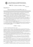
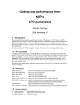
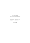
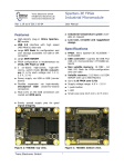
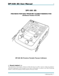
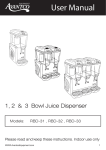
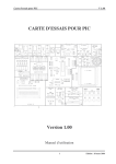
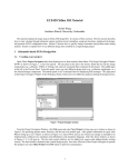
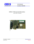
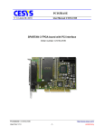
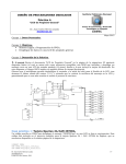
Ball Blasters Redux Manual and System Information Josh Fromm Vikash Gunreddy 1 Index 1. Basic System Description (Page 3) 2. User Manual (Page 5) 3. State Machine Diagram (Page 12) 4. State Machine Detailed Description (Page 14) 5. System Hardware Overview (Page 18) 6. Detailed Description of Hardware (Page 19) 7. Place and Route Report (23) 2 Basic System Description: The system is a hardware implementation of a single player game of the space odyssey genre. The game is implemented using a Xilinx Spartan-‐3E board that employs a XC3S500E FPGA. The game takes user input using an NES compliant joystick, an on-‐board rotary encoder, and four on-‐board slide switches. The board outputs visual data through a standard FPGA connection and outputs audio data through a modified speaker. Image 1: Ball Blasters board with part labelling Part Number Part Description 1 Power Connector and Power Switch 2 Speed Control Dial 3 3 VGA Port 4 Boot/Music Jumpers 5 Ball Count Control Switches 6 JoyStick Connection 7 Speaker Connection Game Backstory: In the near dystopian future, mankind has encountered alien life. Dubbed Balls due to their ellipsoid physiology and spacecraft design, although there were initial thrilling space skirmishes between the two, Balls and Humans have improved their relations immensely in the past several space years. You were charged with representing humans in the upcoming peace and economic space-‐summits that are to be held on the Ball home world Circulon. As your sizeable diplomatic fleet warped into orbit around Circulon, the Balls revealed that they are as traitorous as they are round (very). A massive Ball armada was waiting for your arrival! Before you could organize your fleet, the Ball ships began their linear assault; crashing into and destroying all ships but your own. Stunned, you survey the debris field that was once humanities pride. Among the wreckage you see many intact life pods; some of the crew managed to escape! Before you can start collecting the life pods, the balls begin a second attack. You’ll need to out manoeuvre them using projectile weapons and your ships ability to turn (technologies far too advanced for the Balls). Your diplomatic journey has ended. Your new mission is simple: save as many survivors as possible, and Blast Balls. Good luck Captain. 4 User Manual: Before powering on the board, check to be sure the jumpers shown in the image below are correctly in place. Proper jumper positioning is needed for the game to properly boot up. Image 2: Proper jumper positioning for booting the game Next, it is useful to check that all accessory hardware is properly connected. First make sure that an NES compliant joystick is plugged into the proper general IO pins of the board. Also assure that the games speaker is connected to its proper IO pins. Both plugins can be seen in the image below. 5 Image 3: proper connections for JoyStick (left) and Speaker (right) The ball blaster board must be connected to a 5 Volt barrel jack power supply. Once connected, the board can be turned on by using the power switched shown below. When powered, the board’s power LED will turn on as shown. 6 Image 4: Proper power connection Once powered on, the user will see the introduction screen to the game, which should read “Ball Blasters Redux”. At this time, if the user would like the game’s soundtrack to play, they should change the position of the jumpers as shown in the following image. 7 Image 5: Proper Jumper Positioning for music to play Upon removing a jumper, the user should notice a totally jammin’ soundtrack begin to play. At this point, the user should begin playing the game. Game Rules: When first turned on, the game will display a simple welcome screen that shows the message “Ball Blasters Redux”. When the B button is pressed, the game will begin. The player controls a highly advanced triangular spacecraft that is capable of firing lasers and warping around the fringes of the screen. Red and green balls will periodically spawn along the edges of the play zone. One red ball will spawn every 3 seconds and one green ball will spawn every 5 seconds. The balls all have a random trajectory and will bounce off of the games borders. It is the player’s goal to blast 8 red balls and collect green balls. To blast red balls, the player can fire a laser from his ship by pressing the A button. The laser will project out of the triangle in the direction that the ship was last moving and destroy any red balls that it collides with. Note that the laser will not be destroyed when hitting a red ball; it will continue to move through space (potentially blasting many balls). The laser will disappear when it reaches the edge of the screen. Note that only a single laser can exist at a time and pressing A while a laser is active will do nothing. A blasted red ball will trigger a popping sound and add one to the players score (which is displayed at the top of the screen). The player is also encouraged to collect green balls by piloting his ship and colliding with the green balls. When a green ball is collected, a collection sound will trigger and a point will be added to the players score. Note that the laser has no effect on green balls. It is of paramount importance that the player avoids colliding his spacecraft with a red ball, as this will end the game. When a red ball collision occurs an explosion noise will be heard and the game will transition to the game over screen, which shows the players final score. In order to play again, the player simply presses the B button. 9 Image 6: Joystick Control Labelling Controls: A Button The A button is used to fire lasers. B Button The B button starts the game JoyStick The Joystick controls the movement of the triangle 10 Ball Control The ball control switches determine how many balls will be active on the screen at a time. The switches represent the number of the maximum number of a single colour of balls that will spawn at a time. The position of the switches is the binary number of balls that will spawn minus one. Speed Dial The speed dial determines how fast the player-‐controlled triangle will move. The current speed of the triangle is shown on the board’s LEDs. 11 Hardware Manual: The core of the game is the ball_blaster.vhd file. This file contains the main state machine used to implement Ball Blasters Redux, so it is a useful exercise to first fully examine its operation before further delving into the peripherals that support it. Following is a block diagram of the state machines transitions and a tail giving a detailed explanation of each state. 12 13 State Reset Welcome Screen Display Welcome Message Start & Display Welcome Message Wait Game Screen Background Draw Line Start & Draw Line Draw Triangle Select Draw Triangle Load Description The state machine transitions to this state when the reset button is pressed. It then transitions to Welcome Screen state. The state machine waits in this state until all display pixels are set to Yellow color and then transitions to Display Welcome Message Start. These 2 states form a for-loop. The welcome message is “Ball Blasters Redux”. Display Welcome Message Start state is the loop-condition i.e. it checks if number of characters (char_counter) equals 17. • If NO, it pulses the “start” signal of character_generator entity to start drawing the current character and transitions to Display Welcome Message state. Once the character is drawn, character_generator pulses its “done” signal, and state transitions back to Display Welcome Message Start state after incrementing char_counter. • If YES, it transitions to Wait state. The state machine waits in this state until the user presses joystick button B. It then transitions to Game Screen Background state The state machine waits in this state until all display pixels are set to Black color and then transitions to Draw Line Start state. These 2 states form a for-loop. There are 5 lines, each identified by line_id. The process for line_id is a case statement which changes line_id to the next line that is to be drawn. Once the final line is drawn, line_id is set to NULL_LINE. Draw Line Start state is the loopcondition i.e. it checks if line_id equals NULL_LINE. • If NO, it pulses the “start” signal of line_plotter entity to start drawing the current line and transitions to Display Line state. Once the line is drawn, line_plotter pulses its “done” signal, and state transitions back to Draw Line Start state after changing line_id. • If YES, it transitions to Draw Triangle Select state. This state is used to select triangle object in ObjSys entity and transitions to Draw Triangle Load. In this state, the triangle’s current co-ordinates are registered in triangle_x and triangle_y registers (used for 14 Draw Triangle Start Draw Triangle Draw Laser Select Draw Laser Load Draw Laser Start Draw Laser Draw Green Select, Draw Green Load, Draw Green Ball Start & Draw Green Ball Draw Red Select, Draw Red Load, Draw Red Balls Start & scoring), while ObjSys calculates new triangle coordinates. Transitions to Draw Triangle Start state. This state pulses character_generator’s “start” signal to start drawing the triangle and transitions to Draw Triangle state. Once the triangle is drawn, character_generator pulses its “done” signal, and state transitions to Draw Laser Select state. This state is used to select laser object in ObjSys entity and transitions to Draw Laser Load. In this state, the laser’s current co-ordinates are registered in laser_x and laser_y registers (used for scoring), while ObjSys calculates new laser coordinates. Transitions to Draw Laser Start state. This state pulses character_generator’s “start” signal to start drawing the laser and transitions to Draw Laser state. Once the laser is drawn, character_generator pulses its “done” signal, and state transitions to Draw Green Select state. These 4 states form a for-loop. The number of green balls is given by ball_count which is set using slide switches. Draw Green Select state is the loop-condition i.e. it checks if number of green balls (char_counter) equals ball_count. • If NO, it selects a green ball in ObjSys and transitions to Draw Green Load state which reads the green ball’s current co-ordinates for scoring, while ObjSys calculates new green ball co-ordinates. Transitions to Draw Green Ball Start state which pulses character_generator’s “start” signal to start drawing a green ball and transitions to Draw Green Balls state. Once the green ball is drawn, character_generator pulses its “done” signal, and state transitions back to Draw Green Select state after incrementing char_counter. • If YES, it transitions to Draw Red Select state. While in Draw Green Balls state, score is incremented based on triangle’s and current green ball’s position i.e. if triangle captures the green ball (“point” signal is high). These 4 states form a for-loop. The number of red balls is given by ball_count which is set using slide switches. Draw Red Select state is the loop-condition i.e. it checks if number of red balls (char_counter) equals ball_count. 15 Draw Red Balls Display Game Info Start & Display Game Info Done Game Over Background Display Game Over Message Start & Display Game Over Message If NO, it selects a red ball in ObjSys and transitions to Draw Red Load state which reads the red ball’s current co-ordinates for scoring, while ObjSys calculates new red ball coordinates. Transitions to Draw Red Ball Start state which pulses character_generator’s “start” signal to start drawing a red ball and transitions to Draw Red Balls state. Once the red ball is drawn, character_generator pulses its “done” signal, and state transitions back to Draw Red Select state after incrementing char_counter. If however, “impact” signal is high in Draw Red Balls state i.e. triangle and red ball have collided, then state transitions to Game Over Background state. • If YES, it transitions to Display Game Info Start state. While in Draw Red Balls state, score is incremented based on laser’s and current red ball’s position i.e. if laser kills the red ball (“kill” signal is high). These 2 states form a for-loop. The message is “Score ###”. Display Game Info Start state is the loopcondition i.e. it checks if number of characters (char_counter) equals 8. • If NO, it pulses the “start” signal of character_generator entity to start drawing the current character and transitions to Display Game Info state. Once the character is drawn, character_generator pulses its “done” signal, and state transitions back to Display Game Info Start state after incrementing char_counter. • If YES, it transitions to Done state. This state indicates that one frame has been completed. It waits for the VGA timer (@ 20 Hz) to expire to transition back to Game Screen Background state to redraw the frame. Draw Red Balls state transitions to this state if “impact” signal is high. The state machine waits in this state until all display pixels are set to Yellow color and then transitions to Display Game Over Message Start state. These 2 states form a for-loop. The message is “Game Over! \n Score ###”. Display Game Over Message Start state is the loop-condition i.e. it checks if number of characters (char_counter) equals 17. • If NO, it pulses the “start” signal of character_generator entity to start drawing the • 16 End current character and transitions to Display Game Over Message state. Once the character is drawn, character_generator pulses its “done” signal, and state transitions back to Display Game Over Message Start state after incrementing char_counter. • If YES, it transitions to End state. The state machine waits in this state until the user presses joystick button B. It then transitions to Reset state to restart the game. 17 System Hardware Overview: Now that the state machine has been covered, the purpose of other blocks should be more clearly apparent. Following is a block diagram showing the hardware interaction of the entire system. 18 Detailed Hardware Description: Following is a detailed description of each file and how it plays into the system as a whole. Binary_to_bcd: This file simply converts an 8 bit binary value to a digit ASCII number in base 10. This file is needed for converting the players score into the appropriate numbers to display on the game screen. The raw score data is output from the main state machine, converted into ASCII BCD and then output to the character_generator which goes on to display the numbers. Character_generator: The character generator file is one of two main drawing modules in the system. Character generator takes an address (of the character to be displayed) and a position as input and writes that character to the VGA frame memory. This is done through close interaction with the font rom (which contains all bit patterns) and binary to bcd (which is used to generate addresses for numbers). Line_plotter: The line plotter file implments Bresenham’s algorithm for plotting straight lines. This file is used to create the border of the game screen and writes directly to the frame buffer. Dp_64kx3_ram: This file is designed such that Xilinx will synthesize a large chunk of memory as easily accessible block RAM. The memory is used as the frame buffer for the VGA output. As such, displaying an object or character requires a write to the appropriate address in the RAM and the VGA controller will simply read and output the entire frame buffer each update. Note that each address space in this ram corresponds to 3 bits, the RGB value for the associated pixel. Font_rom: The font rom takes an address as input and outputs an according 8 bit pattern. Each character or object has an 8 by 8 bit pattern stored on the font rom 19 which can be accessed by incrementing through the address allocated to each character. These 8 by 8 bit patterns go on to be processed and stored in the frame buffer for display. VGA_controller: The VGA controller file accesses the systems frame buffer and generates the necessary control signals for a 256x256 3 bit color output. This is done by iterating through the frame buffer and outputting corresponding pixel color patterns at the times indicated by supporting VGA peripherals. VGA_counter: This file implements a simple counter that is used to aid the VGA controller in generating correct control signals. VGA_pulse_gen: This file generates a high output when the count value in VGA counter is within a specified range. This pulse is then used to generate control signals in the VGA controller. VGA_pulse_high_low: This file implements a simple module to generate a pulse when a high to low transition occurs on the horizontal sync data line generated by the VGA pulse gen file. This pulse is then sued to increment the vertical sync counter in VGA_counter, which is needed for proper VGA control signals. Debouncer: The debouncer file implements control modules for on board hardware input. Specifically, a control module is made for the set of 4 slide switches on the Spartan board and a control module is made for the rotary encoder on the Xilinx board. The sliding switch control module debounces input data before sending it off the main state machine, where it is used to control the number of active balls. The rotary encoder control module implements a simple state machine to determine which way, if any, the rotary encoder is being turned. When the encoder is rotated, the module creates a rotation event which is used in the main state machine to control a counter that is used to set the speed of the player controlled triangle. 20 Flash_controller: The flash controller module implements a state machine that accesses data from the board’s parallel flash memory, which contains audio data. The module reads data from two locations; a byte is read from the theme song memory space and a byte is read from the memory space of an extra sound effect. The module then determines which sound is to be output based on a select input line and outputs the appropriate byte to the DAC for enough cycles to give a 44 KHz sampling frequency. Sigma_delta_dac: The DAC module implements a simple 8 bit first order sigma delta DAC. The DAC takes input from the flash controller and outputs directly to the system’s speaker through general IO. Joystick: The joystick file implements a state machine which produces the signals necessary to input data from an NES compliant joystick. The 8 bits of raw data are latched after finishing a full read. The latched data is used in JoyInterpret to generate the movement signals needed by the rest of the system. JoyInterpret: The JoyInterpret file simply converts raw joystick data into more workable forms. ObjUpdate: The ObjUpdate file implements each type of object processing element needed by the game. The types of processing elements are: ball, laser, and triangle. Each processing element represents a single on screen object. The processing element is entirely responsible for keeping track of and updating the objects position, including interactions with boundaries. Inter-‐object interaction, such as the collision between a laser and a red ball, is handled by the main state machine. When one of these events is detected, an object’s processing element can be accessed with control signals through ObjSys. 21 ObjSys: The purpose of ObjSys is simply to instantiate all the processing elements needed by the game. ObjSys also implements a large multiplexer for selecting data from one of the many processing elements and decoder for enabling a single element to receive control logic. Timer: The timer file implements a simple variable period timer, which is a useful thing to have. For more specific information about how each file works, see the attached folder which contains all VHDL code. 22 Xilinx Place & Route Report: Following is the place and route report for the finished Ball Blasters project. This report gives information about the utilization of the FPGA. Note that the report can also be found in a more cleanly formatted form in the folder this manual is located in. Release 9.2.04i par J.40 Copyright (c) 1995-‐2007 Xilinx, Inc. All rights reserved. ECEXILINXVM:: Tue Jun 04 01:31:53 2013 par -‐w -‐intstyle ise -‐ol std -‐t 1 ball_blaster_map.ncd ball_blaster.ncd ball_blaster.pcf Constraints file: ball_blaster.pcf. Loading device for application Rf_Device from file '3s500e.nph' in environment C:\Xilinx92i. "ball_blaster" is an NCD, version 3.1, device xc3s500e, package fg320, speed -‐4 Initializing temperature to 85.000 Celsius. (default -‐ Range: -‐40.000 to 100.000 Celsius) Initializing voltage to 1.140 Volts. (default -‐ Range: 1.140 to 1.320 Volts) Device speed data version: "PRODUCTION 1.27 2007-‐10-‐19". Design Summary Report: 23 Number of External IOBs 69 out of 232 29% Number of External Input IOBs 21 Number of External Input IBUFs 21 Number of LOCed External Input IBUFs 21 out of 21 100% Number of External Output IOBs 48 Number of External Output IOBs 48 Number of LOCed External Output IOBs 47 out of 48 97% Number of External Bidir IOBs 0 Number of BUFGMUXs 1 out of 24 4% Number of DCMs 1 out of 4 25% Number of RAMB16s 12 out of 20 60% Number of Slices 3133 out of 4656 67% Number of SLICEMs 76 out of 2328 3% Overall effort level (-‐ol): Standard Placer effort level (-‐pl): High Placer cost table entry (-‐t): 1 Router effort level (-‐rl): Standard Starting initial Timing Analysis. REAL time: 4 secs 24 Finished initial Timing Analysis. REAL time: 4 secs WARNING:Par:288 -‐ The signal sf_sts_IBUF has no load. PAR will not attempt to route this signal. Starting Placer Phase 1.1 Phase 1.1 (Checksum:994bf6) REAL time: 6 secs Phase 2.7 WARNING:Place:837 -‐ Partially locked IO Bus is found. Following components of the bus are not locked: Comp: sf_A<25> WARNING:Place:838 -‐ An IO Bus with more than one IO standard is found. Components associated with this bus are as follows: Comp: sf_A<0> IOSTANDARD = LVCMOS33 Comp: sf_A<1> IOSTANDARD = LVCMOS33 Comp: sf_A<2> IOSTANDARD = LVCMOS33 Comp: sf_A<3> IOSTANDARD = LVCMOS33 Comp: sf_A<4> IOSTANDARD = LVCMOS33 Comp: sf_A<5> IOSTANDARD = LVCMOS33 Comp: sf_A<6> IOSTANDARD = LVCMOS33 Comp: sf_A<7> IOSTANDARD = LVCMOS33 Comp: sf_A<8> IOSTANDARD = LVCMOS33 Comp: sf_A<9> IOSTANDARD = LVCMOS33 Comp: sf_A<10> IOSTANDARD = LVCMOS33 Comp: sf_A<11> IOSTANDARD = LVCMOS33 Comp: sf_A<12> IOSTANDARD = LVCMOS33 Comp: sf_A<13> IOSTANDARD = LVCMOS33 25 Comp: sf_A<14> IOSTANDARD = LVCMOS33 Comp: sf_A<15> IOSTANDARD = LVCMOS33 Comp: sf_A<16> IOSTANDARD = LVCMOS33 Comp: sf_A<17> IOSTANDARD = LVCMOS33 Comp: sf_A<18> IOSTANDARD = LVCMOS33 Comp: sf_A<19> IOSTANDARD = LVCMOS33 Comp: sf_A<20> IOSTANDARD = LVCMOS33 Comp: sf_A<21> IOSTANDARD = LVCMOS33 Comp: sf_A<22> IOSTANDARD = LVCMOS33 Comp: sf_A<23> IOSTANDARD = LVCMOS33 Comp: sf_A<24> IOSTANDARD = LVCMOS33 Comp: sf_A<25> IOSTANDARD = LVCMOS25 INFO:Place:834 -‐ Only a subset of IOs are locked. Out of 48 IOs, 47 are locked and 1 are not locked. If you would like to print the names of these IOs, please set the environment variable XIL_PAR_DESIGN_CHECK_VERBOSE to 1. Phase 2.7 (Checksum:1312cfe) REAL time: 6 secs Phase 3.31 Phase 3.31 (Checksum:1c9c37d) REAL time: 6 secs Phase 4.2 ...... Phase 4.2 (Checksum:98a2ff) REAL time: 7 secs Phase 5.30 Phase 5.30 (Checksum:2faf07b) REAL time: 7 secs Phase 6.3 26 Phase 6.3 (Checksum:39386fa) REAL time: 7 secs Phase 7.5 Phase 7.5 (Checksum:42c1d79) REAL time: 7 secs Phase 8.8 ............................................... .......... ............................................... ........ ........ .... Phase 8.8 (Checksum:ffb5df) REAL time: 26 secs Phase 9.5 Phase 9.5 (Checksum:55d4a77) REAL time: 26 secs Phase 10.18 Phase 10.18 (Checksum:5f5e0f6) REAL time: 36 secs Phase 11.5 Phase 11.5 (Checksum:68e7775) REAL time: 36 secs REAL time consumed by placer: 37 secs CPU time consumed by placer: 34 secs Writing design to file ball_blaster.ncd Total REAL time to Placer completion: 38 secs Total CPU time to Placer completion: 35 secs 27 Starting Router Phase 1: 19349 unrouted; REAL time: 40 secs Phase 2: 17792 unrouted; REAL time: 41 secs Phase 3: 4572 unrouted; REAL time: 44 secs Phase 4: 4572 unrouted; (0) REAL time: 44 secs Phase 5: 4572 unrouted; (0) REAL time: 45 secs Phase 6: 4572 unrouted; (0) REAL time: 45 secs Phase 7: 0 unrouted; (0) REAL time: 49 secs Phase 8: 0 unrouted; (0) REAL time: 50 secs WARNING:Route:455 -‐ CLK Net:joy_timer/pulse may have excessive skew because 4 CLK pins and 0 NON_CLK pins failed to route using a CLK template. WARNING:Route:455 -‐ CLK Net:screen_update may have excessive skew because 0 CLK pins and 194 NON_CLK pins failed to route using a CLK template. Total REAL time to Router completion: 51 secs Total CPU time to Router completion: 48 secs Partition Implementation Status -‐-‐-‐-‐-‐-‐-‐-‐-‐-‐-‐-‐-‐-‐-‐-‐-‐-‐-‐-‐-‐-‐-‐-‐-‐-‐-‐-‐-‐-‐-‐ No Partitions were found in this design. 28 -‐-‐-‐-‐-‐-‐-‐-‐-‐-‐-‐-‐-‐-‐-‐-‐-‐-‐-‐-‐-‐-‐-‐-‐-‐-‐-‐-‐-‐-‐-‐ Generating "PAR" statistics. ************************** Generating Clock Report ************************** +-‐-‐-‐-‐-‐-‐-‐-‐-‐-‐-‐-‐-‐-‐-‐-‐-‐-‐-‐-‐-‐+-‐-‐-‐-‐-‐-‐-‐-‐-‐-‐-‐-‐-‐-‐+-‐-‐-‐-‐-‐-‐+-‐-‐-‐-‐-‐-‐+-‐-‐-‐-‐-‐-‐-‐-‐-‐-‐-‐-‐+-‐-‐-‐-‐-‐-‐-‐-‐-‐-‐-‐-‐-‐+ | Clock Net | Resource |Locked|Fanout|Net Skew(ns)|Max Delay(ns)| +-‐-‐-‐-‐-‐-‐-‐-‐-‐-‐-‐-‐-‐-‐-‐-‐-‐-‐-‐-‐-‐+-‐-‐-‐-‐-‐-‐-‐-‐-‐-‐-‐-‐-‐-‐+-‐-‐-‐-‐-‐-‐+-‐-‐-‐-‐-‐-‐+-‐-‐-‐-‐-‐-‐-‐-‐-‐-‐-‐-‐+-‐-‐-‐-‐-‐-‐-‐-‐-‐-‐-‐-‐-‐+ | clock | BUFGMUX_X1Y11| No | 1299 | 0.079 | 0.196 | +-‐-‐-‐-‐-‐-‐-‐-‐-‐-‐-‐-‐-‐-‐-‐-‐-‐-‐-‐-‐-‐+-‐-‐-‐-‐-‐-‐-‐-‐-‐-‐-‐-‐-‐-‐+-‐-‐-‐-‐-‐-‐+-‐-‐-‐-‐-‐-‐+-‐-‐-‐-‐-‐-‐-‐-‐-‐-‐-‐-‐+-‐-‐-‐-‐-‐-‐-‐-‐-‐-‐-‐-‐-‐+ | screen_update | Local| | 199 | 0.092 | 2.239 | +-‐-‐-‐-‐-‐-‐-‐-‐-‐-‐-‐-‐-‐-‐-‐-‐-‐-‐-‐-‐-‐+-‐-‐-‐-‐-‐-‐-‐-‐-‐-‐-‐-‐-‐-‐+-‐-‐-‐-‐-‐-‐+-‐-‐-‐-‐-‐-‐+-‐-‐-‐-‐-‐-‐-‐-‐-‐-‐-‐-‐+-‐-‐-‐-‐-‐-‐-‐-‐-‐-‐-‐-‐-‐+ | joy_timer/pulse | Local| | 16 | 1.486 | 3.318 | +-‐-‐-‐-‐-‐-‐-‐-‐-‐-‐-‐-‐-‐-‐-‐-‐-‐-‐-‐-‐-‐+-‐-‐-‐-‐-‐-‐-‐-‐-‐-‐-‐-‐-‐-‐+-‐-‐-‐-‐-‐-‐+-‐-‐-‐-‐-‐-‐+-‐-‐-‐-‐-‐-‐-‐-‐-‐-‐-‐-‐+-‐-‐-‐-‐-‐-‐-‐-‐-‐-‐-‐-‐-‐+ * Net Skew is the difference between the minimum and maximum routing only delays for the net. Note this is different from Clock Skew which is reported in TRCE timing report. Clock Skew is the difference between the minimum and maximum path delays which includes logic delays. The Delay Summary Report The NUMBER OF SIGNALS NOT COMPLETELY ROUTED for this design is: 0 The AVERAGE CONNECTION DELAY for this design is: 1.125 The MAXIMUM PIN DELAY IS: 7.607 29 The AVERAGE CONNECTION DELAY on the 10 WORST NETS is: 6.153 Listing Pin Delays by value: (nsec) d < 1.00 < d < 2.00 < d < 3.00 < d < 4.00 < d < 8.00 d >= 8.00 -‐-‐-‐-‐-‐-‐-‐-‐-‐ -‐-‐-‐-‐-‐-‐-‐-‐-‐ -‐-‐-‐-‐-‐-‐-‐-‐-‐ -‐-‐-‐-‐-‐-‐-‐-‐-‐ -‐-‐-‐-‐-‐-‐-‐-‐-‐ -‐-‐-‐-‐-‐-‐-‐-‐-‐ 10908 5318 1898 802 417 0 Timing Score: 0 Number of Timing Constraints that were not applied: 1 Asterisk (*) preceding a constraint indicates it was not met. This may be due to a setup or hold violation. -‐-‐-‐-‐-‐-‐-‐-‐-‐-‐-‐-‐-‐-‐-‐-‐-‐-‐-‐-‐-‐-‐-‐-‐-‐-‐-‐-‐-‐-‐-‐-‐-‐-‐-‐-‐-‐-‐-‐-‐-‐-‐-‐-‐-‐-‐-‐-‐-‐-‐-‐-‐-‐-‐-‐-‐-‐-‐-‐-‐-‐-‐-‐-‐-‐-‐-‐-‐-‐-‐-‐-‐-‐-‐-‐-‐-‐-‐-‐-‐-‐-‐-‐-‐-‐-‐-‐-‐-‐-‐-‐-‐-‐-‐-‐-‐-‐-‐-‐-‐-‐-‐ Constraint | Check | Worst Case | Best Case | Timing | Timing | | Slack | Achievable | Errors | Score -‐-‐-‐-‐-‐-‐-‐-‐-‐-‐-‐-‐-‐-‐-‐-‐-‐-‐-‐-‐-‐-‐-‐-‐-‐-‐-‐-‐-‐-‐-‐-‐-‐-‐-‐-‐-‐-‐-‐-‐-‐-‐-‐-‐-‐-‐-‐-‐-‐-‐-‐-‐-‐-‐-‐-‐-‐-‐-‐-‐-‐-‐-‐-‐-‐-‐-‐-‐-‐-‐-‐-‐-‐-‐-‐-‐-‐-‐-‐-‐-‐-‐-‐-‐-‐-‐-‐-‐-‐-‐-‐-‐-‐-‐-‐-‐-‐-‐-‐-‐-‐-‐ PERIOD analysis for net "clock_dcm" deriv | SETUP | 22.415ns| 17.585ns| 0| 0 ed from NET "clock_int" PERIOD = 20 ns H | HOLD | 0.639ns| | 0| 0 IGH 50% | | | | | -‐-‐-‐-‐-‐-‐-‐-‐-‐-‐-‐-‐-‐-‐-‐-‐-‐-‐-‐-‐-‐-‐-‐-‐-‐-‐-‐-‐-‐-‐-‐-‐-‐-‐-‐-‐-‐-‐-‐-‐-‐-‐-‐-‐-‐-‐-‐-‐-‐-‐-‐-‐-‐-‐-‐-‐-‐-‐-‐-‐-‐-‐-‐-‐-‐-‐-‐-‐-‐-‐-‐-‐-‐-‐-‐-‐-‐-‐-‐-‐-‐-‐-‐-‐-‐-‐-‐-‐-‐-‐-‐-‐-‐-‐-‐-‐-‐-‐-‐-‐-‐-‐ NET "clock_int" PERIOD = 20 ns HIGH 50% | N/A | N/A| N/A| N/A| N/A -‐-‐-‐-‐-‐-‐-‐-‐-‐-‐-‐-‐-‐-‐-‐-‐-‐-‐-‐-‐-‐-‐-‐-‐-‐-‐-‐-‐-‐-‐-‐-‐-‐-‐-‐-‐-‐-‐-‐-‐-‐-‐-‐-‐-‐-‐-‐-‐-‐-‐-‐-‐-‐-‐-‐-‐-‐-‐-‐-‐-‐-‐-‐-‐-‐-‐-‐-‐-‐-‐-‐-‐-‐-‐-‐-‐-‐-‐-‐-‐-‐-‐-‐-‐-‐-‐-‐-‐-‐-‐-‐-‐-‐-‐-‐-‐-‐-‐-‐-‐-‐-‐ All constraints were met. 30 INFO:Timing:2761 -‐ N/A entries in the Constraints list may indicate that the constraint does not cover any paths or that it has no requested value. Generating Pad Report. All signals are completely routed. WARNING:Par:283 -‐ There are 1 loadless signals in this design. This design will cause Bitgen to issue DRC warnings. Total REAL time to PAR completion: 53 secs Total CPU time to PAR completion: 50 secs Peak Memory Usage: 220 MB Placement: Completed -‐ No errors found. Routing: Completed -‐ No errors found. Timing: Completed -‐ No errors found. Number of error messages: 0 Number of warning messages: 7 Number of info messages: 1 Writing design to file ball_blaster.ncd PAR done! 31 32