1
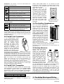
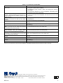
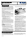
AUTOCOM-200 AUTOCOM-200 User’s Manual Personal Response System 1. INTRODUCTION active. This will prevent the automatic transmission of an Inactivity Alert to the response center. 1.1 Guidance for the Impatient Reader If you consider system overviews and descriptions as a waste of time, it is quite clear that you are eager to get to the heart of the matter very quickly. You, the impatient reader, are advised to skip the rest of this section. Start with Section 2 - "Equipment Description" - and learn the function of each control and indicator. After this, skip Section 3 and proceed directly to Section 4 "Using the AUTOCOM-200". All the initial information you need is given right there. Nevertheless, keep the manual handy for later use. Questions that arise after a while will find their answers between the pages you didn't read on the first encounter. 1.2 What Can this System Do? The AUTOCOM-200 is an advanced, programmable personal response system designed for keeping constant watch over you via the public telephone network. The party at the far end of the line – the supervisor – is an employee of a professional response center, entrusted with the task of looking after you and sending help if necessary. The AUTOCOM-200 can be programmed by the installer to call four telephone numbers. Once the call is answered, the following types of coded message may be sent out: • Requests for Help: see Section 4, Para. 4.1. • Fire or Panic Alarms: see Section 4, Para. 4.2. • Inactivity Alerts: see Section 4, Para. 4.3 • Periodic Test Reports: see Section 4, Para. 4.6. • System Maintenance Reports: see Section 4, Para. 4.7. After sending out HELP, ALARM and INACTIVITY codes (which are "priority messages"), the AUTOCOM-200 becomes responsive to "tone burst" commands sent by the response center over the telephone line. Certain commands enable your supervisor to establish a hands-free conversation link with you (see Section 4, Para. 4.4). Other commands are used by the supervisor to control emergency devices within or near your residence, such as an electrical lock, a siren or a flashing emergency light (see Section 4, Para. 4.5). 1.3 Which Auxiliary Devices are Available? An AUTOCOM-200 system consists of the AUTOCOM-200 console (see Figure 1-1) and auxiliary devices, some of which are optional. The following auxiliary devices may be included: • HELP pushbuttons: These pushbuttons, if installed, will be mounted near your bed and in other convenient locations. • Once you press a HELP button, the AUTOCOM-200 will proceed to establish communication with the response center and to send out a request for help. • RESET pushbuttons: These pushbuttons, if installed, will also be mounted near your bed and in other convenient locations. Press any one of the RESET buttons at least once within a time period determined by your installer, to inform the AUTOCOM-200 that you are well and physically Figure 1-1. The AUTOCOM-200 Console • • • • • • Wireless devices (see Figures 2-1, 2-2): These are miniature wireless transmitters and detectors which perform functions identical with those performed by their wire-connected counterparts. You can control the AUTOCOM-200 from anywhere within your residence, by carrying single or multifunction pushbutton type transmitters. Each pushbutton is dedicated to a special task. You can therefore: • Request HELP: see Section 4, Para. 4.1. • Send an alarm message: see Section 4, Para. 4.2. • Prove that you are active: see Section 4, Para. 4.3. • Operate control circuits C1 and C2 see Sec. 4, Para. 4.5. An auxiliary speakerphone (see Figure 2-3): This is an optional hands-free intercom device, which complements the speakerphone module included within the AUTOCOM-200. When mounted in remote parts of your residence such as the basement, the balcony or the back yard – this unit will allow the supervisor at the response center to converse with you, even though you are too far from the original speakerphone. Activity detectors (see Figure 2-4): Optional motion detectors may be installed in the bathroom and in the kitchen. They are triggered by your movement across their field of view. Upon detection of movement, they reset the AUTOCOM-200 and prevent the automatic transmission of an inactivity alert. Smoke detectors: An optional smoke detector added to the system will cause the AUTOCOM-200 to send out a fire alarm to the response center if a fire breaks out. Panic button: An optional PANIC pushbutton added to the system will cause the AUTOCOM-200 to send out a PANIC alarm to the response center if pressed in an emergency. Long range transmitter: An optional long range wireless encoder-transmitter may be connected to the system for automatic transmission of calls for help and inactivity alert messages to the response center. 2. EQUIPMENT DESCRIPTION 2.1 The AUTOCOM-200 Console Figure 2-1 shows the AUTOCOM-200 console with the sloping front panel, where the 5 pushbuttons and 2 indicators are located. The top part is designed as a recessed platform, on which your DE7411U telephone set may be placed. This telephone can be used for regular conversations while the AUTOCOM-200 is not active. Note: This telephone is automatically disconnected from the line when the AUTOCOM-200 is triggered into action. 1 Pushbuttons: the functions of the five control buttons are explained in the following table: Control Function/Effect Depress briefly to initiate a call for help. Press down briefly at least once within a time period determined by your installer to prove activity. Depress briefly to stop any type of ongoing communication with the response center. Depress briefly to activate the 1st remote controlled device (electrically operated door). Depress briefly to activate the 2nd remote controlled device (siren or strobe light). Indicators: the functions of the luminous indicators are explained in the following table: Indicator (Green) Function/Effect Illuminates when the electrical mains supply is in order. Extinguishes upon power failure. Illuminates while the telephone line is engaged by the AUTOCOM-200. Extinguishes when the AUTOCOM-200 disengages the line. Note: The programmer's keypad, located on the underside of the AUTOCOM-200 console, is provided for the exclusive use of the installer. Please refrain from tampering with this keypad. Full programming instructions are provided in the Installer's manual (Publication DE7411-). (Red) 2.2 The MCT-104 Transmitter If your AUTOCOM-200 system includes optional 4-pushbutton transmitter, you will be able to control the system from practically anywhere within your residence, without approaching the system console. The installer will program the four color-coded pushbuttons on your MCT-104 as equivalents of the pushbuttons on the AUTOCOM-200 console. He will also mark them accordingly, thus permitting you to identify the task of each pushbutton Figure 2-1. The MCT-104 at a brief glance. When a pushbutton is pressed briefly, the transmitter sends out a specific code which is received and interpreted by the receiver unit built into the AUTOCOM-200. The desired function will be carried out as if the equivalent button were pressed on the AUTOCOM-200 console. Note: The indicator on the transmitter's panel should light steadily upon pressing any one of the four pushbuttons. If it flickers, the 12-volt battery may be exhausted. For battery replacement, refer to the transmitter's installation manual. Ask your installer to operate the transmitter from various locations within your residence, to make sure there are no "dead" spots from which transmissions might be blocked. 2.3 The MCT-201 Transmitter If your AUTOCOM-200 system includes this optional singlechannel transmitter, you will be able to control a single function from practically anywhere within your residence, without approaching the system console. The installer can program the system to execute any one of the 6 available functions: HELP / RESET / FIRE ALARM / PANIC / C1 / C2, whenever you press the MCT-201 transmit pushbutton. The desired function will be carried out as if the equivalent button were pressed on the AUTOCOM-200 console. Note: The indicator on the transmitter's panel should light steadily upon pressing the button. If it flickers, the 12-volt battery may be exhausted. For battery replacement, refer to the transmitter's own installation manual. Ask your installer to operate the transmitter from various locations within your residence, to make sure there are no "dead" spots from which transmissions might Figure 2-2. The MCT-201 be blocked Pendant Transmitter 2.4 The Auxiliary Speakerphone One or two auxiliary speakerphones may enhance your AUTOCOM-200 system, provided that they are installed where you habitually spend some time every day. They will ensure reliable two-way conversation between yourself and the response center – when you happen to be at those particular locations. Please remind your installer to initiate communications with the response center, for checking how well your speech is received at the far end of the line. Also ask him to adjust the loudspeaker volume level, for receiving the supervisor's voice loud and Figure 2-3. The clear in the desired location. Note: Be sure to protect the speaker- Auxiliary Speakerphone phone's installation site from water and high humidity . Instructions for using speakerphones for two-way speech are given in Para 4.4. 2.5 Activity Detectors Passive infrared (PIR) motion detectors may be used to provide the AUTOCOM-200 with proof that you are normally active. Using them relieves you of the responsibility to press the RESET button once within a time period determined by your installer your installer. A wide range of wireless and hardwired detectors may be used equally well for this purpose Figure 2-4. Samples of they are all compatible with the Passive IR Motion Detectors AUTOCOM-200. Figure 2-5 lets you get acquainted with the shapes of two popular passive infrared motion detectors - the SRN-2000 and the CORAL. Whenever you cross the coverage area of a motion detector, situated, for example, in a corridor leading to the bathroom – your motion will be detected and the detector will activate a switch which resets your AUTOCOM-200. If reset on time, the AUTOCOM-200 will refrain from sending out an "inactivity alert" to your supervisors in the response center. 3. PROCESS DESCRIPTION When the AUTOCOM-200 is triggered into action, it follows a predetermined sequence of operations, as explained in the following paragraphs. 2 3.1 Pre-dialing Warning and Dialing A. The AUTOCOM-200 may be programmed by the installer to delay the dialing process by 0 to 255 seconds, and to sound a DE7411U repetitive warning throughout this delay. The warning signal heard when dialing is about to begin resembles the opening notes of Beethoven's fifth symphony – three short notes followed by a long note (see Figure 3-1). The pre-dialing warning enables you to press the STOP button and cancel transmission to the response center in case of inadvertent activation of the AUTOCOM-200. Figure 3-1. Pre-dialing Warning Note: There is no pre-dialing warning if the message to be transmitted is a periodic test code (sent out automatically during sleeping hours), or a system maintenance code. B. After the pre-dialing warning, the AUTOCOM-200 starts dialing the four telephone numbers, at the order determined by your installer. In case of a request for help, an alarm or an inactivity alert, the dialing process will be echoed through the loudspeaker, to assure you that dialing is indeed taking place (this "echo" may be turned off by the installer). C. The telephone numbers programmed by the installer are dialed one by one until one of the communication attempts succeeds or until the maximum number of dialing attempts is reached (as programmed by the installer). At the end of the communication session, the AUTOCOM-200 reverts to the "standby" state, ready for the next activation. 3.2 The Communication Session A. As a call comes through, the response center operator can react in three different ways: • conduct a two-way hands-free conversation with you (Para 4.4). • activate emergency devices in your household (Para 4.5). The remote operator can do this while still engaged in conversation with you. • terminate the communication session immediately by "commanding" the AUTOCOM-200 to go "on hook". B. Your AUTOCOM-200 will go "on hook" automatically after 60 seconds, unless "ordered" by the response center operator to maintain communication. After going "on hook", the AUTOCOM-200 will start a new standby period (a direct result of a successful communication session). Note: The response center operator can continue communicating with you as long as he wishes by sending periodic commands that prevent the AUTOCOM-200 from going "on hook". 4. USING THE AUTOCOM AUTOCOM-200 -200 IMPORTANT! You may press the STOP button to cancel transmission of a request for help, an alarm or an inactivity alert. This can be done at any point in time while the "pre-dialing warning" sounds, during the dialing process or while the message is already being transmitted. 4.1 Requesting Help If you need HELP, press any one of the following pushbuttons: • The HELP button on the AUTOCOM-200 front panel. • The auxiliary HELP button installed at a convenient place (near your bed, for example). • The HELP button on your hand-held wireless transmitter. When the call for help reaches your supervisor, he will most probably try to talk to you via the speakerphone, to check what kind of troble you are in. This is where the speakerphone becomes useful (see Para 4.4). 4.2 Dealing with Fire or Panic Alarms FIRE and PANIC alarms are priority messages. The appropriate alarm code will be sent to the response center if: • A smoke detector wired to your AUTOCOM-200 detects smoke - a fire alarm code will be sent out automatically. • You press a Fire alarm pushbutton installed anywhere within your reach (the installer may also provide you with a fire alarm pendant transmitter). • You press a PANIC pushbutton installed anywhere within your reach (the installer may also provide you with a panic alarm pendant transmitter). When the alarm code reaches your supervisor, he will most probably try to talk to you via the speakerphone, to get more details on the emergency at hand. This is where the speakerphone becomes useful (see Para 4.4). 4.3 Proving Activity INACTIVITY is a priority message. As long as your life at home runs its regular course, you are considered to be "active". Being active is a normal state which does not require supervisor intervention. However, it will be your duty to press any one of the RESET button at least once within a time period determined by the installer, thus informing the AUTOCOM-200 that you are active. • Press the RESET button on the AUTOCOM-200 console. • Press an auxiliary RESET button installed at a convenient place (near your bed, for example). • Press the button on your wireless RESET transmitter. DE7411U In addition, you may ask your installer to mount a motion detector in the corridor leading to the toilet or the bathroom, and wire this detector as an automatic RESET switch. Whenever you enter the corridor, your movement will be detected and the AUTOCOM-200 will be automatically reset, without pressing any button. The time limit for proving activity is usually 12 or 24 hours; if for some reason you do not press the RESET button and the 12 or 24 hours expire with no proof of activity – an "inactivity alert" code will be sent out to the response center (unless you manage to STOP the transmission). An inactivity alert code received at the response center draws attention to the fact that you have been inactive, and the remote supervisor is expected to respond as if a request for help had been received (see end of Paragraph 4.1 above). Note: If you have to leave home for a few days, you may ask the installer to disable the activity monitoring function. At any rate, you may cancel the inactivity alerts temporarily by pressing the front panel RESET button 3 times in a row. If done so, a warning beep will sound once every 30 minutes to remind you that activity monitoring has been suspended. To reactivate the activity monitoring when you return home, press RESET once. 4.4 Using the Speakerphone Once communication is established with the response center for sending any one of the 3 priority messages (HELP, FIRE/ PANIC ALARM AND INACTIVITY), the speakerphone will be switched to the "LISTEN" mode, allowing the response center operator to listen to the sounds within your residence. If you speak then, the operator (your supervisor) will hear your voice. IMPORTANT: • The speakerphone is remote-controlled by tone bursts sent by your supervisor. He is likely to listen briefly and then switch to the SPEAK mode to address you via the loudspeaker. • Unlike a regular telephone conversation, in which you can interject a few words while the other party speaks, the speakerphone allows one way speech at a time (back and forth exchange of speech). This is a method normally used in military and commercial radio communication. You must always wait until your supervisor stops talking and switches the speakerphone from "SPEAK" to "LISTEN" by sending a tone command, composed of two consecutive, short tone bursts. When you hear the tone bursts over the loudspeaker, you will know that it is your turn to speak. • When you speak, explain your situation as briefly as possible. As soon as you finish talking, your supervisor will switch the speakerphone back to the "SPEAK" mode, and his reply will again be broadcast by the loudspeaker. 3 • The AUTOCOM-200 console accommodates an integral speakerphone, but auxiliary speakerphones may be added to the system (see Para. 2.4). Although the speakerphones employ sensitive microphones, it is preferable to speak not too far from the unit for loud and clear voice communication. Try to remain within 3 to 4 m (10 to 13 ft) from the speakerphone. 60 seconds after receiving the last "tone burst" command, the AUTOCOM-200 sounds a reminder signal – two short notes followed by a long note – then waits 10 seconds and goes off the line. The purpose of this reminder is to give the remote supervisor a chance to prolong the communication session by another 60 seconds. If the supervisor chooses not to react, the communication session will end abruptly. 4.5 Operating Emergency Devices The two control circuits C1 and C2 provided by the AUTOCOM-200 can be wired by your installer to control a large variety of emergency devices. Consult your installer about the use of these circuits. The following instructions are based on an example, where the control circuits have been wired to perform the following functions: • Control circuit 1 (C1) opens an electrical lock or activates a wireless long-range encoder-transmitter to send out a call for help. • Control circuit 2 (C2) switches on a flashing light above the main entrance to your residence, to attract the attention of the help team sent over by your supervisor. Once a message has been received from your AUTOCOM-200, and while telephone communication is still maintained, your remote supervisor can send tone burst commands over the telephone line to activate control circuits C1 and C2. Under certain conditions, however, you might wish to control these circuits yourself. If so, refer to the following instructions: To unlock the front door, you can press: • The original C1 button on the AUTOCOM-200 front panel. • An auxiliary C1 button installed at a convenient spot (near your bed, for example). • The C1 button on your hand-held wireless transmitter. To activate the flashing light, you can press: • The original C2 button on the AUTOCOM-200 front panel. • An auxiliary C2 button installed at a convenient spot (near your bed, for example). • The C2 button on your hand-held wireless transmitter. After a control circuit has been activated, its deactivation is subject to prior programming by the installer. For instance, each circuit can be activated momentarily, with immediate automatic deactivation. Alternatively, permanent activation may be selected, and deactivation will be possible by pressing the STOP button. Consult your installer about the operating mode selected for control circuits C1 and C2. 4.6 Periodical Tests Once correctly installed and programmed, the AUTOCOM-200 automatically sends test reports to the response center at regular intervals, as programmed by your installer. Each periodic test transmission demonstrates to the supervisor on duty that your AUTOCOM-200 and your telephone line are still in working order. Test transmissions take place quietly during sleeping hours. Note: If for some reason you do not wish test reports to be sent out, you may ask the installer to disable this function. 4.7 System Maintenance provide long-term, unfailing service. It is only natural that a failure in either power source would be a reason for concern. The battery in your miniature wireless transmitter can not last forever. If a transmitter's battery becomes weak, the response center must be automatically notified. The response center is informed on power source failures by automatic system maintenance reports. These reports do not require any action on your part, but require your attention, because a power failure or a low battery may degrade the dependability of your system. • Mains power failures / recoveries: Report codes indicating these events are sent out automatically to the response center. Upon loss of mains power, a rhythmical beeping sounds but the event is reported after 30 minutes. If you hear a rhythmical beeping and the AC indicator doesn't light - a "power down" situation exists. You can silence the buzzer by pressing the RESET pushbutton, but it will sound again after 6 hours (if the power down condition persists that long). Once the electrical power is restored, the AUTOCOM-200 waits 30 minutes and then reports the new situation to the response center. • Backup battery failures / recoveries: Report codes indicating these events are sent out automatically to the response center. If the battery voltage falls below a preset threshold, a rhythmical beeping sounds and the event is reported. If you hear a rhythmical beeping and the AC indicator lights normally - a "low battery" situation exists. You can silence the beep by pressing the RESET pushbutton. Once the battery is recharged or replaced with a good one, the AUTOCOM-200 waits 30 minutes and then reports the new situation to the response center. Note: a battery switch is located on the rear panel of the AUTOCOM-200. If you inadvertently place this switch in the OFF position (with the lever fully to the left), the buzzer will sound and the AUTOCOM-200 will report a "low battery" to the response center. If you hear a rhythmical beeping and the AC indicator lights normally, it is advisable to verify that the battery switch is in the ON position (the lever must be always shifted fully to the right when viewed from the rear). • Transmitter battery failure: If a portable transmitter's battery becomes weak and the transmitter's pushbutton is pressed, a LOW BATTERY condition is reported to the AUTOCOM-200 in addition to the transmitter's own identification. The AUTOCOM200, in turn, will report this to the response center. Response center personnel can then call you and tell you to replace the battery, or they may send someone to replace the battery for you. It is recommended to make a test transmission with each hand-held miniature transmitter at least once in two months. This way, a weak battery will be discovered in time to assure continuous reliable operation of these transmitters. To test a transmitter, call the response center and inform the operator that you are about to make a test. Also ask him to report to you if any one of your transmitters sends out a "low battery" message. Next, push the button of each transmitter in turn at 5 minute intervals. The AUTOCOM-200 will dial out in response to signals received from HELP, AUX1, AUX2 transmitters, regardless of the transmitter's battery condition, but a "low battery" message will be sent out only if the transmitter's battery is exhausted. The AUTOCOM-200 will dial out in response to signals received from other transmitters only if the transmitter's battery is exhausted. Note: Battery recovery in a wireless transmitter is not reported by the system. An uninterrupted electrical mains supply and a fully charged backup battery are required if the AUTOCOM-200 is expected to 5. TESTING THE SYSTEM The AUTOCOM-200 system must be periodically tested, to verify that all functions pre-programmed and enabled by the installer are carried out correctly. Periodic testing is also important for verifying the state of the battery in each pendant transmitter (the transmitter reports a low battery condition to the AUTOCOM-200 when its pushbutton is pressed). 4 Before starting the test, call the response center by telephone, telling the shift operator that you are about to conduct a test. Ask him to establish voice communication with you upon receiving a message from your AUTOCOM-200. When your supervisor is ready to conduct the test, proceed in accordance with the steps in Table 5-1 below. DE7411U TABLE 5-1. SYSTEM TEST PROCEDURES Your Action (1) Press the HELP pushbutton on the AUTOCOM200 console. (2) Speak with the supervisor from various parts of the room, asking him whether he can hear you. If an auxiliary speaker phone is installed, announce your intention to test it. (3) Approach the other speakerphone, and ask the supervisor how well he can hear you from various positions. (4) Ask the supervisor to enable control circuit C1. (5) Ask the supervisor to enable control circuit C2. Correct Result • The Pre-dialing Warning sounds repeatedly (three short notes followed by a long note – if this function is enabled). • The Response Center's number is called. The message (tone bursts) is transmitted. • The supervisor addresses you via the loudspeaker, stops talking and a tone burst sounds over the loudspeaker. • The supervisor assures you that he can hear you at his end of the line. • A tone burst sounds on the loudspeaker. This serves as your cue to talk once more. • The supervisor assures you that he can hear you through the other speakerphone. • A tone burst sounds over the loudspeaker. The device controlled by C1 will be activated (a door lock for instance, will unlock). The device controlled by C2 will be activated (a flashing light, for instance, will start flashing). • The session is terminated. • The AUTOCOM-200 revert to the standby state. (6) Ask the supervisor to terminate the session. Note: if you skip this, the session will terminate automatically after about 60 seconds. (7) Try out all other HELP buttons, including the • The session is terminated. HELP transmitter. When the pre-dialing warning • The AUTOCOM-200 reverts to the standby state. sounds, press the AUTOCOM-200 STOP button. (8) Try out all available PANIC buttons (including The Pre-dialing Warning sounds repeatedly. Once you press the STOP transmitters). If the pre-dialing warning sounds, press button, the AUTOCOM-200 reverts to the standby state. the AUTOCOM-200 STOP button. (9) Press the C1 button on the AUTOCOM-200 The device controlled by C1 will be activated (a door lock, for instance, will console. unlock).* (10) Press STOP on the AUTOCOM-200 console. The device controlled by C1 will be deactivated.* (11) Press the C2 button on the AUTOCOM-200 The device controlled by C2 will be activated (a flashing light, for instance, will console. start flashing).* (12) Press STOP on the AUTOCOM-200 Console. The device controlled by C2 will be deactivated.* * The C1 and C2 test results depend on the way the installer programmed these circuits to function (see Installer's manual for the various options). If you have extra C1 and C2 buttons installed, or transmitters that perform these functions, try them out as well. VISONIC LTD. (ISRAEL): P.O.B 22020 TEL-AVIV 61220 ISRAEL. PHONE: (972-3) 645-6789, FAX: (972-3) 645-6788 VISONIC INC. (U.S.A.): 10 NORTHWOOD DRIVE, BLOOMFIELD CT. 06002-1911. PHONE: (860) 243-0833, (800) 223-0020 FAX: (860) 242-8094 VISONIC LTD. (UK): FRASER ROAD, PRIORY BUSINESS PARK, BEDFORD MK44 3WH. PHONE: (0870) 730-0800 FAX: (0870) 730-0801 INTERNET: www.visonic.com VISONIC LTD. 2003 AUTOCOM-200 DE7411U (REV. 3, 06/03) Refer to warranty statement in the installation Instructions DE7411U 5