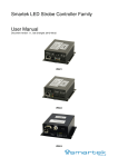
1
MultiScreen 4 Hardware and software system for real time monitoring of multiple sources of video and audio signals. User’s Manual Contents Chapter 1. Components and installation for the system . . . . . . . . . . . . . . . . . . . . . . . . . . . . . . . . . .3 Chapter 2. Interface of Stream MultiScreen . . . . . . . . . . . . . . . . . . . . . . . . . . . . . . . . . . . . . . . . . . . . . 6 Chapter 3. Database and reporting . . . . . . . . . . . . . . . . . . . . . . . . . . . . . . . . . . . . . . . . . . . . . . . . . . . . 15 Chapter 4. Configuring system . . . . . . . . . . . . . . . . . . . . . . . . . . . . . . . . . . . . . . . . . . . . . . . . . . . . . . . . .21 2 Chapter 1. Components and installation for the system Stream Multi Screen includes following components: Server MultiScreen 4.x; Client MultiMonitor 4.x; DB Server Microsoft SQL Server 2008 R2 Express SP1; Keyboard for remote control (optional); SNMP extension agent – extension for processing of SNMP requests CVBS/SDI/HDSDI/DVBIPTV/RTMP/HTTP live stream. Server Stream MultiScreen 4.X carries out following functions: Displaying input signals for visual monitoring; Reception, processing and analysis of input streams IPTV/SDI/ASI/CVBS/RTMP; Alarm Detection and saving alarms into database; Distribution of alarms via e-mail, SNMP. Client MultiMonitor 4.x carries out following functions: Configuration of servers Stream MultiScreen 4.X; Alerts operator about audio and video malfunctions; Review and export of alerts to reports/files. DB server is for storage of summary report, which contains alerts detected by Stream MultiScreen. Report also contains status of Stream MultiScreen servers, namely: start and stop of servers, switch between configurations, etc. All components of Stream MultiScreen could be installed either on the same PC or distributed across several PCs. Stream MultiScreen and DB server must be installed on the same local network. If necessary, MultiScreen client might be configured for access from WAN. In general, the system may include several instances of Stream MultiScreen and several instances of Stream MultiMonitor client. Optionally system may include DB server for storage of alerts, which could be excluded from installation if only visualization of input streams is needed. All components have its own installations. 3 Recommended schema for installation of Stream MultiScreen IP: Picture above depicts: Client – dedicated PC with installed client MultiMonitor. This PC controls and entire system. There is also special programmable keyboard (optional). Stream MultiScreen servers which are being used for reception, analysis and monitoring of IPTV streams. Centralized storage for reports - DB server Microsoft SQL Server Express. 4 Recommended schema for installation of Stream MultiScreen HD-SDI/SDI/CVBS: Picture above depicts: Client – dedicated PC with installed client MultiMonitor. This PC controls and entire system. There is also special programmable keyboard (optional). Stream MultiScreen servers which are being used for reception, analysis and monitoring of IPTV streams. Centralized storage for reports - DB server Microsoft SQL Server Express. 5 Chapter 2. Interface of Stream MultiScreen Interface of main window of MultiScreen Server. When MultiScreen Server starts, window with information about start up time, elapsed time and server ID shows up (see Fig. 1). Next line contains information about license. (USB dongle must be inserted for proper work). Licenses are being issued for SD, HD and audio channels and also for quantity of windows and audio indicators for concurrent. Note: if values for all licenses equal zeros, then make sure that drivers are installed on USB dongle. Start Windows Device Manager and if you see unidentified device, install drivers from folder C:/ProgramFiles/StreamLabs/Multiscreen4/drivers Fig. 1 Main window of MultiScreen Server. Below is a list of keyboard shortcuts for MultiScreen server: CTRL+Q – shutdown server. CTRL+M – minimize/maximize windows. CTRL+I – overlay windows with information about services. CTRL+Space – cleanup log with alerts in database. 6 Interface for MultiMonitor Fig. 2 shows main window of MultiMonitor. Bold frames and digits parcel out areas for different tasks. Fig. 2 Main window of MultiMonitor 1. «Objects tree». It shows common elements with established connection. Those elements comprise Stream MultiMonitor itself, Stream MultiScreen servers and client for access to database. Objects tree is a main control of system, which allows to select, review and change setting for all components 2. Properties of selected object. It allows of review properties of selected object. For instance, server “Test” was selected and you may review licenses, server version, etc. 3. Work panel. Use of this area depends on mode of application. On Fig. 2 it’s grayed out (inactive). For other modes it can display workflow, configuration editor for Stream MultiScreen; or detailed text messages. 4. Table with messages. It displays error messages, change of state of client and also communication part between client and server(s). Double-click on any line in table open up detailed description in work panel. There is small toolbar in a left upper corner of the table for view settings for details. 7 5. Toolbars for control of MultiMonitor functions. Fig. 3 Toolbars Area on a Fig. 3 consists of several independent toolbars. Group 1 is for view settings for major controls of MultiMonitor. Buttons are described in left to right order: Show/HIde Toolbox; Show/HIde objects tree; Show/HIde properties of selected object; Show/HIde table with messages. MultiMonitor allows saving for delayed review current state of objects tree. Group2 is handling this functionality. Buttons are described in left to right order: Reset objects tree to initial state. Panel gets refreshed and all servers and corresponding settings will be lost; Retrieve saved objects tree from storage; Save current objects tree; Search for servers with subsequent addition; Export settings for server; Export settings for server. Group 3 is for work with database server. It is being enables only if access above mentioned server has been set up. Setup procedure is described in detail in chapter “Setup access to database server”. Buttons are described in left to right order: Show in work panel list of registered MultiScreen servers. Show in work panel history of launches of MultiScreen servers. Show in work panel list of registered alarms. Show in work panel list of registered sources of alarms. Show in work panel list of registered objects – sources of alarms. Show in work panel history of registered objects. Show in work panel list of registered alert events. 8 Group 4 is for work with State panel. Setup of State panel is described in detail in chapter «Setup of State panel». Buttons are described in left to right order: Clear all sound alarms and their history on all connected servers; Open window for monitoring; Default setting (monitoring mode). Group 5 is for work with wizard for visual design of monitoring windows. Work with Wizard if described in detail in chapter «Wizard for visualization design». This toolbar is enabled only if Wizard has been launched. Work with objects tree Panel with objects tree is a main element for control over system. It allows fulfilling following settings and operations: Setup general parameters: access to DB, access to SNMP server, alert settings; Search for Stream MultiScreen servers within LAN; Review state and configure Stream MultiScreen servers; Configure template for unit of visualization; Configure monitoring. Work with objects of the tree is being conducted with help of toolbar located at the top of panel. Toolbar is shown on a Fig. Fig. 4 Toolbar for control over objects tree Certain actions could be executed for object selected from objects tree. Buttons in toolbar are assigned for every action. Some action could be executed using “hot keys”. Buttons are described in left to right order: «Property sheet (Alt + Enter)» - show property panel with properties of object selected in objects tree; «Connect» - establish connection with server; «Disconnect» - interrupt connection with server; «Search (Ctrl + Shift + F)» - search for objects within selected category. For instance, if Servers category is selected and Search button is pressed, then search for servers within LAN will be executed; «Set (Ctrl + S)» - set/apply selected parameters on server. It must be done in order to make this parameters active and permanent; «Get (Ctrl + G)» - get current state of object from server; 9 «Add (Insert)» - add new object; «Remove (Del)» - remove object; «Move up (Alt + Up)» - move object up in a tree branch; «Move down (Alt + Down)» - move object down in a tree branch; «Refresh (F5)» - synchronize state of object in a tree with state of object on a MultiScreen server; «View designer (F2)» - edit visual design for monitoring; «Export item to file» - export of settings and configuration of server into file; «Import items from file» - load settings and configuration from file. For each selected object only subset of buttons is enabled for permitted actions. Main categories of Tree objects are shown on Fig. 5 below: Fig. 5 Tree objects «System settings» – global settings which could be exported to one or several MutliScreen servers. “Personal” settings for server are identical to global and could be found in subcategory “Settings”. They are described in detail in chapter “Review of subcategories of server in objects tree”; «Screen view layout templates» – list of available templates which are being used by Wizard during design. Work with templates is described in detail in chapter “Wizard for visualization design”; «Servers» – list of servers added to objects tree. Addition of servers to objects tree is described in detail in chapter “Addition of MultiScreen servers»; «Multi monitoring» – editor for Monitoring Mode. Detailed review of this mode is contained in document «Stream MultiScreen Monitoring guide». Addition of MultiScreen server Stream MultiMonitor application includes module for search of Stream MultiScreen servers within LAN. Select category “Servers” and press «Search» button in toolbar. Result is shown on a picture below. 10 Fig. 6 Search and addition of servers “Search” module scans entire LAN for available servers and sends requests to them. All found servers are displayed in «Search results» window. Select server form the list «Search results» and press «Add» button. Grayed out «Add» means that server has been added already to objects tree. “Search” module also allows adding servers manually using IP address. Manual addition might be needed in cases when requests are not being intercepted by serves because of specific settings in LAN. Let’s do following: 1. 2. 3. 4. Expand « Search options» group. Select «Stop search. Edit search target list - add or remove specific IP». Enter IP address into editable field: “IP address” located in toolbar and press «Add» button. Select «Perform search. Send search requests and gather responses». Search request will be sent to a given address and, in case of acknowledgment, this server will be listed in «Search results». Review of “Server” branch in objects tree Setup and review of Stream MultiScreen server parameters is being utilized using “Objects tree panel”. First, server had to be found and added to tree as described in previous paragraph. 11 Note: icon with green dot next to it indicated successful connection to Stream MultiScreen. Fig. 7 MultiScreen server categories Server contains following entries: Hardware, Settings, and Configurations. Hardware displays information about devices connected to server: List of connected PC monitors; List of Audio devices; IP interfaces; Video/audio capture cards; GPIO devices. Fig. 8 Hardware subcategories Hardware is for information only and does not assume any changes for parameters. Settings – contains next subcategories: Monitoring – setup of connection to SQL server; Mail robot – configuration of E-mail distribution; Alarms – settings for alert events for given server; Server time zones – list with Timezones; Pictures – templates for clock. Fig. 9 Settings subcategories 12 “Settings” for server differs from global “Settings” at the top of tree. Former applies only to a given server, whereas latter applies to all servers found within LAN and added to the tree. Besides global “Settings” do not have subcategories “Server time zones” and ”Pictures”. - Monitoring – saving of logs could be toggled on/off. Also lifespan of storage could be designated. Setup of access to database is described in chapter «Setup of access to DB server». Mail robot – setup of mail robot for email distribution of alert messages. Detailed description of setup you will find in chapter «Setup of Mail Robot». Alarms – list with alert events intercepted by MultiScreen. Application allows setting up alert events individually for each channel. Setup is described in chapter «Setup of alert events». - Server time zones – list with time zones. For information only. - Pictures – template for clock. For information only. Configuring server Category «Configurations» contains list with available configurations for server. Configuration is a full set of parameters which defines monitoring of the server. It comprises: parameters of incoming streams, selection of services, visual design of monitoring windows and PPM indicators, parameters of alert events and properties of monitoring windows. Stream MultiScreen server can handle only one configuration at the time. However, server is able to store several prepared configuration with parameters which could be reviewed in Stream MultiMonitor application. At the first launch of Stream MultiScreen server an empty configuration is being created and loaded automatically. Stream MultiMonitor allows altering name of configuration. Select configuration in category «Configurations» of given server and change name in the «Properties» panel. Press «Set» in toolbar for objects tree. Switching between configurations of server. In order to do that follow the procedure: Select necessary server form objects tree; Select configuration for «Active config» property in Property panel; Press «Set» button in toolbar for objects tree. 13 Fig. 10 Switching between configurations Note: active configuration is marked by red checkmark in a list of configurations. Also name of active configuration is displayed next to corresponding server in objects tree. Addition of configuration for the server For addition of new configuration do the following: Select category «Configurations» in objects tree; Press button «Add» in a toolbar for objects tree; Dialog window will pop up; enter name of new configuration and press «OK»; If you want to make new configuration active, follow procedure described in a previous paragraph. Removal of existing configuration for the server For removal of existing configuration for the server do the following: Select necessary configuration for server, chosen in category «Configurations»; Press button «Remove». Confirm removal in window Confirm remove operation». Note: active configuration cannot be removed. That’s why you have to switch to another configuration first as described in chapter «Switching between configurations of server». Then remove unneeded configuration. Review of configuration for the server Fig. 11 presents configurations in objects tree. 14 Fig. 11 Structure of server configuration Server configuration comprises following groups of components: «Signal sources» - description of all incoming HD-SDI/SDI/CVBS/ASI sources; «Streams» - description of all incoming IPTV and RTMP streams. Description of IPTV stream includes network parameters and actual tables PAT, PMT and SDT; «Services» - Contains description and settings of services for corresponding streams; «Screen Views» - contains list of prepared visualization designs. Visualization design – it is set of video windows, PPM indicators and text labels which are displayed on one of the monitors of the server; «Media Windows» - contains list of active media windows. Media window of server - it is element of graphic interface of Stream MultiScreen server, which defines the correspondence between visualization design and PC monitor; «Audio players» - list of active audio devices. Chapter 3. Database and reporting In order to set up an access to database follow the procedure: Select either subcategory «Monitoring» in category System settings or in subcategory Settings for added server; Select property «Connection string» in «Properties» panel and press button «…». Select DB server and DB name (default is MultiMonitor ) in popped up dialog window; Set property «Is enabled» to True in «Properties» panel. 15 Fig. 12 Settings for access to DB server Default settings for DB MultiMonitor : Login ID – «MultiScreen4» and password «MultiScreen_4». Note: in order to test connection to DB open window «App. Server Event list». To configure access to DB server do the following: Setup access as described in previous paragraph; Launch Stream MultiScreen server; Using MultiMonitor application make a search for servers and establish connection to needed Stream MultiScreen server as described in chapter «Addition of MultiScreen server»; Select category «Monitoring» and set parameters in «Properties» panel; 16 Set property «Store logs» to «True»; Press button «Set» in toolbar for objects tree; Restart Stream MultiScreen server in order to activate settings for access to DB server . Fig, 13 Setup of access of Stream MultiMonitor to DB server Fig, 14 Setup of access of Stream MultiMonitor to DB server In case of successful connection to DB server, property «State» in category «Monitoring» will change to «Operating» 17 Fig. 15 Setup of Auto Cleanup for database Note: you should enable Auto Cleanup of DB on one of the servers. Set life span of stored data to maximum. Day is unit of measure. MultiMonitor Monitoring – review of reports with alerts Application MultiMonitor Monitoring allows real time reviewing reports about work of Stream MultiScreen servers. Reports contain records about alerts, generated by Stream MultiScreen servers. Note: setup access to data base in order to review reports. Press button «Server event list» in MultiMonitor Monitoring toolbar. Report will show up in work panel. Fig.16 Panel with report «Server Event List» 18 Panel consists of 2 parts – table with records and toolbox on a top. Toolbox is shown on Fig. 17 below. Fig. 17 Toolbox for report «Server Event List» Toolbox is used for report update and setting of view filters: 1. «Auto refresh» - toggles on/off auto update of report. It allows automatic appending of new records generated by server. 2. «Refresh» - synchronizes data on server and view in table. 3. «Max Rows» - sets max number of rows in table. Higher number increases load on server. 4. «Server» - filters in only records for selected server. 5. «Event Type» - filters in events of certain type. 6. «Event Source» - filters in events for selected source. 7. «From» and «To» - filter in timestamps of events. Note: filters could be combined for refined filtering. Table of report is shown below: Fig. 18 Table with records 19 Structure of the record is as follows: 1. 2. 3. 4. 5. «id» - unique id of event in database; «Type» - type of record: «Error», «Warning», «Info» and «Verbose»; «Server» - server, which generated alert and subsequently record; «Event Source» - component of server configuration, source of alert; «Start time» and «End time» - start and end time of event. Blank «End time» means that event is still in progress; 6. «Duration» – duration of event. Export of MultiMonitor Monitoring into .XML file MultiMonitor Monitoring not only displays reports, but also allows exporting of reports into .XML files for subsequent work with then in Excel. Following steps have to be performed: 1. Open panel for review of alerts as described in chapter «MultiMonitor Monitoring – review of reports with alerts». 2. Set up filters as needed and as described in chapter «MultiMonitor Monitoring – review of reports with alerts»; then press «Refresh». 3. Left click on «Save» in toolbar MultiMonitor Monitoring as shown on Fig. 19: Fig. 19. Export report with alerts into file 4. Assign name and storage location in popped up dialog window. 20 Chapter 4. Configuring system Setup of Mail Robot Settings for mail server MultiMonitor Designer allows setting up connection with mail server, which will distribute reports about work of MultiScreen servers using email. Fig. 20 shows Properties for selected Mail Robot in objects tree. Let’s go through the setting in Property panel for object Mail Robot in objects tree. Designate address of SMTP server in «SMTP Server» -> Server field which is being used for incoming SMTP connections and encryption. In case if SMTP server requires user authentication, it is necessary checkmark «Authentication» box and enter users login and password into fields «login» and «Password» otherwise «Authentication» box has to be unchecked. Fig. 20. Settings for Mail robot Server supports 3 encryption modes, which are describes in table below. Mode None STARTTLS Port 25 587 Comment No encryption. Mail is transmitted as is. During connection client and server coordinate mechanism for encryption. Encrypted channel might be used. TLS 465 Encrypted channel is used. Note: For incoming connections SMTP server may use ports which are distinct from ports which are spelled out in a table. 21 Test of connection to mail server In order to check connectivity, test email could be sent. Fig. 21 Test of connectivity to SMTP server Conduct following steps: 1. 2. 3. 4. 5. Setup SMTP server as described above; Enter sender email address into field «Sender mail» ; Select option «Send test mail»; Enter recipient address into field «Test mail send to»; Apply settings pressing button «Set» in toolbar of objects tree. Server will immediately generate outgoing email. In case of success record «Test mail successfully sent» will be added to the table in «Output» panel of MultiMonitor and recipient will receive email with subject «MultiScreen 4.X SMTP Server connection test message». In case of failure, line with error description will be added to «Output» panel. Note: diagnostics of the problem may take some time. Settings for email distribution In order to enable email distribution select option «Is enabled» in Property panel «Mail robot» for object Mail robot. Also designate address in the field «Sender mail» for sender, under whose name distribution will be conducted. 22 Note: SMTP server can reject e-mail sending with unknown sender address. Parameter «Seconds between mails» determines delay between emails, what is actually frequency of distribution. In a beginning server sends out alert message at the first detection of alarm. Then server collects messages during designated interval and sends out emails at the end of interval. Essentially server works in a batch mode. If interval between alarms overlaps interval between batches then email is being sent upon next detected alert. You can group reports by alert type and send emails to several addressees. Designate address(es) in subcategory Alarms for server in objects tree or in subcategory Alarms in System settings. Settings for alarms are described in chapter «Setup for Alarms». Addition of HD-SDI/SDI/CVBS streams The following steps have to be performed: Select category «Signal sources» for active configuration in objects tree. Press button «Add» in toolbar of objects tree. Select «Type of signal source» - SDI source, CVBS source or HDSDI source in pop-up dialog «Add signal source to active configuration»; Select input of circuit board from drop down menu «Streaming device input»; Designate name of source in the field «Name»; Select audio mode «Analog» or «Embedded» from drop down menu «Audio mode»; Select video standard from drop down menu «System». Press «OK». Fig.22 Addition of HD-SDI/SDI/CVBS streams to active configuration Note: addition of «ASI Source» is reviewed in chapter «Addition of ASI Sources». 23 Stream MultiMonitor supports automation for addition of HDSDI/SDI/CVBS streams: Addition to configuration of all AV inputs simultaneously if all inputs receive identical streams: o Select «HDSDI source/SDI source/CVBS» from drop down menu «Type of signal source; o Select «All» from drop down menu «Streaming device input»; o Select audio mode from drop down menu «Audio mode»; o Select video standard of all signal sources from drop down menu «System»; o Press «OK». Modification of settings for HDSDI/SDI/CVBS stream Fig. 23 Properties of HDSDI/SDI/CVBS stream Once HDSDI/SDI/CVBS stream is selected in objects tree, its properties are displayed in «Properties» panel. You can change those properties within this panel. In order to make new properties permanent, press button «Set» in toolbar for objects tree. Removal of HDSDI/SDI/CVBS streams The following steps have to be performed: Select needed HDSDI/SDI/CVBS stream from active configuration in «Signal sources». Press button «Remove» in toolbar of objects tree. Confirm removal in pop-up window «Confirm remove operation». 24 Note: all services and coders/decoders associated with HDSDI/SDI/CVBS stream will be removed too. Also links in visualization windows to remote objects, which have been removed will disappear too, although windows itself and PPM indicators will be still present in visualization design. Monitoring of transport streams Stream MultiScreen is bale to process IP streams, which suffice requirements of chapter «2.4 Transport Stream bit stream requirements» of ISO/IEC 138181-1 standard «Information technology — Generic coding of moving pictures and associated audio information: Systems». MultiScreen receives IP input streams according to specification ETSI TS 102 034 «Digital Video Broadcasting (DVB); Transport of MPEG-2 TS Based DVB Services over IP Based Networks». Two types of packets are supported - UDP and d RTP. Switch between modes is automatic, based on analysis of input streams. Also ASI signals may be used as transport streams. MultiScreen works with packet sizes 188 and 204 bites. Switch of modes is automatic, based on analysis of input data. There is no error correction for 204 bite packet; additional 16 bites for correction of errors of Reed Solomon are ignored. MultiScreen allows monitoring of following parameters: presence of input signal; presence of synchronization of transport stream; asynchronization of transport stream; errors in transport stream; presence of table PAT; errors during transmission of PAT; correspondence of transmission speed to designated speed limits; presence of selected service in PAT; presence of PMT table for selected service; errors during transmission of PMT table for selected service; errors during transmission of timestamps for selected service; correspondence of bit speed of selected service to designated limits of speed; presence of selected elementary streams; errors during transmission of elementary stream; scrambling of elementary streams; still images/freeze frames in decoded video; black frame in decoded video; level of audio. In case of successful reception of IP stream, Stream MultiScreen distributes information about PAT (Program Association Table) , PMT (Program Map Table) and SDT (Service Description Table). Information is being sent in order of reception of tables. Stream MultiMonitor is able to display PAT, PMT and SDT. Sample is shown on a Fig. 24 below. 25 Fig. 24 Tables PAT, PMT and SDT in objects tree Addition of ASI streams to configuration For addition of transport stream DVB-ASI, incoming via serial interface, the following steps have to performed: Select category «Signal sources» from active configuration. Press button «Add» in toolbar for objects tree. o Select ASI source from drop down menu «Type of signal source» in pop-up dialog «Add signal source to active configuration»; o Select input of circuit board from drop down menu «Streaming device input»; o Designate name of signal in the field «Name»; o Designate bitrate speed (Kbit/sec) of incoming transport stream in the field «Bitrate». Fig. 25 Addition of ASI signal to active configuration Addition of DVB-ASI transport stream to configuration is described in chapter «Addition of IP/ASI streams». 26 Modification of properties of ASI stream Once source of ASI signal has been chosen from objects tree, its properties are being displayed in «Properties» panel as shown on Fig. 26. Fig. 26 Properties of ASI signal «Properties» panel allows altering features of source of ASI signal. In order to make changes permanent press button «Set» in toolbar for objects tree. Removal of source of ASI signal from configuration Following steps have to be performed: Select source of ASI signal from category «Signal sources» in active configuration in objects tree. Press button «Remove» in toolbar for objects tree. Confirm transaction in pop-up window «Confirm remove operation». Note: all services and coders/decoders associated with ASI stream will be removed too. Also links in visualization windows to remote objects, which have been removed will disappear too, although windows itself and PPM indicators will be still present in visualization design. Addition of IP stream Following steps have to be performed: Select category «Streams» from active configuration. Press button «Add» in toolbar for objects tree. o Select «Type of stream» -> «IP Stream» in pop-up dialog window «Add new stream to active configuration» ; 27 o o o Set up properties for IP stream – designate IP address in the field «IP address» for multicast or unicast sources; Designate port in the field «Port», which will receive date; Enter IP address in the field «IP Interface» for network which transmits data. Press «OK». Fig.27 Addition of IP stream to active configuration If option «Source specific Multicast» is check marked (Enabled), it will turn on reception of data for multicast groups filtering in source address according to standard RFC-4607 Source-Specific Multicast for IP. Note: Multiscreen server receives transport streams according to specification ETSI TS 102034 «Transport of MPEG-2 TS based DVB Services over IP Networks». It supports both modes for formation of TS packets – UDP and RTP. Switching between them is automatic. Note: Multiscreen server receives packets with size 180 and 204 bites. Switching between them is automatic. Addition of ASI stream For addition of ASI stream to active configuration following steps have to be performed: Select category «Streams» from active configuration. Press button «Add» in toolbar for objects tree. o Select «Type of stream» -> «ASI Stream» in pop-up dialog window «Add new stream to active configuration» ; o Select ASI source from drop down list «ASI source». Press «OK». 28 Fig. 28 Addition of ASI stream into active configuration Modification of properties of IP/ASI stream Fig. 29 Properties of IP stream Once IP/ASI stream is selected in objects tree, «Properties» panel displays its properties as shown on Fig. 28. «Properties» panel allows changing of properties of IP/ASI stream. Press button «Set» in toolbar for objects tree and changes will go into effect. 29 Removal of IP/ASI stream For removal of IP/ASI stream from active configuration perform following steps: Select needed IP/ASU stream from «Streams» in active configuration; Press button «Remove» in toolbar for objects tree; Confirm transaction in pop-up window «Confirm remove operation»; Note: all services and coders/decoders associated with IP/ASI stream will be removed too. Also links in visualization windows to remote objects, which have been removed will disappear too, although windows itself and PPM indicators will be still present in visualization. Services and decoders for elementary streams Stream MultiScreen server supports following monitoring: presence of required service if table for programs (PAT); presence of table PMT; presence of elementary streams maintained by service; bit rate speed of entire service; Name of service in table SDT. In order to conduct monitoring, required service has to be added to active configuration for the server. Further data processing is based on selection of services and programs from input streams. Services are listed in PAT table. Note: in order to make services available IP stream has to contain PAT. Addition of service For addition of service to active configuration perform following steps: Select «Services» from active configuration for objects tree; Press «Add» in toolbar for objects tree; Make entries in dialog window «Add new Service to active Configuration». This window is described in chapter «Form for addition of service». Press «OK». 30 Fig. 30 Addition of service to active configuration Dialog window for addition of service for HDSDI/SDI/CVBS stream Window is shown on picture below. Fig. 31 Dialog window for addition of service to active configuration Stream MultiMonitor allows adding services for HDSDI/SDI/CVBS streams: Addition of all services for all HDSDI/SDI/CVBS streams: o Select «Signal source service» from drop down list «Type of service»; o Select «All» from drop down list «Signal source»; o Mark check box «Add All signals», if you to want to add services for all input signals. Read in detail in chapter «Services for incoming streams». Addition of one service for all HDSDI/SDI/CVBS streams: o Select «Signal source service» from drop down list «Type of service»; o Select needed HDSDI/SDI/CVBS stream from drop down list «Signal source»; o Mark checkbox «Add All signals» if you need to add all streams. Read detailed description in chapter «Decoders for input streams». 31 Dialog window for addition of service for IP/ASI stream This window is shown on a picture below. Fig. 32 Dialog window for addition of service Stream MultiMonitor allows adding services for IP/ASI streams: For addition of all services contained in PAT for all IP/ASI streams the following steps have to be performed: o Select «All» from drop down list «Transport Stream»; o Select «All» from drop down list «Service name»; o Mark checkbox «Add All Stream Decoders» if you need to add all decoders. Read detailed description in chapter «Stream decoders». For addition of all services, contained in PAT, for selected IP/ASI stream, the following steps have to be performed: o Select needed IP/ASI stream from drop down menu «Transport Stream»; o Select «All» from drop down menu «Service name»; o Mark checkbox «Add All Stream Decoders» if you need to add all decoders. Read detailed description in chapter «Stream decoders». For addition of one of services, contained in PAT, for selected IP/ASI stream, the following steps have to be performed: o Select needed IP/ASI stream from drop down menu «Transport Stream»; o Select needed service from drop down menu «Service name»; o Mark checkbox «Add All Stream Decoders» if you need to add all decoders. Read detailed description in chapter «Stream decoders». For addition of one of services by number, which is not contained in PAT at the moment, the following steps have to be performed : o Select needed IP/ASI stream from drop down menu «Transport Stream»; o Select «Custom» from drop down menu «Service name»; o Enter number in the field «Service no». 32 Removal of service For removal of service form active configuration the following steps have to be performed: Select needed service from «Services» in active configuration in objects tree; Press button «Remove» in toolbar for objects tree; Confirm transaction in pop-up window «Confirm remove operation». Note: all services and coders/decoders associated with ASI stream will be removed too. Also links in visualization windows to remote objects, which have been removed will disappear too, although windows itself and PPM indicators will be still present in visualization design. Decoders for input streams Stream MultiScreen server separates audio and video signals of incoming HDSDI/SDI/CVBS and processes them: Detects absence of incoming stream and generates Alarm «Signal loss»; Detects “frozen” frame in incoming stream. “Frozen” frame or still picture is determined by calculation of average value of difference between two consecutive frames and comparison of this value with predefined threshold during predefined timeframe and generated alarm «Frozen Video»; Detects “black screen” in incoming stream and generates alarm «Black frame»; Detects absence of audio signal for in input stream by measuring audio level and comparison with predefined threshold level during predetermined timeframe and generate alarm «Audio channel signal level: silence»; Detects overload of audio level in incoming stream by measurement of audio level and comparison of max value with predetermined threshold; and generates alarm «Audio channel signal level: overload»; Monitors presence of L&R audio channels in SDI stream. Addition of decoder for input stream For addition of decoder for input stream into active configuration, the following steps have to be performed: Select needed service for HDSDI/SDI/CVBS stream from «Services» for active configuration; Press button «Add» in toolbox for objects tree; Enter values in dialog window «Add new Signal to server». Detailed description is in a chapter «Window for addition of decoder for input stream». Press «OK». 33 Fig. 33. Addition of decoder for input stream Note: decoders could be added automatically along with addition of services. Detailed description is in a chapter «Window for addition of service for HDSDI/SDI/CVBS stream». Window for addition of decoder for HDSDI/SDI/CVBS input stream This window is shown on a picture below: Fig. 34 Window for addition of decoder for input stream MultiMonitor Designer provides following options for addition of decoder for input stream: For addition of all decoders for all services for HDSDI/SDI/CVBS stream the following procedure has to be carried out: o Select «All signals» from drop down menu «Type of signal»; o Select «All» from drop down list «Signal source». For addition of all decoders for one of the services HDSDI/SDI/CVBS stream: o Select «All signals» from drop down list «Type of signal»; o Select needed service from drop down list «Signal source». For addition of decoders for all services for HDSDI/SDI/CVBS stream: o Select «Video signal» from drop down list «Type of signal»; o Select «All» from drop down list «Signal source»; o Select deinterlacing mode from drop down list «Deinterlacing»; 34 o Select ratio from drop down list «Aspect ratio». For addition of decoder for one of the services for HDSDI/SDI/CVBS stream: o Select «Video signal» from drop down list «Type of signal»; o Select needed service from drop down list «Signal source»; o Select deinterlacing mode from drop down list «Deinterlacing»; o Select ratio from drop down list «Aspect ratio». For addition of audio decoder for all services for HDSDI/SDI/CVBS stream: o Select «Audio signal» from drop down list «Type of signal»; o Select «All» from drop down list «Signal source»; o Select needed L&R audio from drop down list «Audio signal pair»; o Select needed audio mode from drop down list «Demux mode». For addition of audio decoder for one of the services for HDSDI/SDI/CVBS stream: o Select «Audio signal» from drop down list «Type of signal»; o Select needed service from drop down list «Signal source»; o Select needed L&R audio from drop down list «Audio signal pair»; o Select needed audio mode from drop down list «Demux mode». Removal of decoder For removal of decoder from active configuration perform following steps: Select needed decoder from «Services» in active configuration in objects tree; Press button «Remove» in toolbar for objects tree; Confirm transaction in dialog window «Confirm remove operation». 35 Decoder for video signal of HDSDI/SDI/CVBS stream – modification of properties Fig. 35 Properties of video decoder for HDSDI/SDI/CVBS stream In order to modify properties of decoder for video signal of HDSDI/SDI/CVBS stream carry out following steps: Select HDSDI/SDI/CVBS from active configuration in «Services» and choose needed decoder; Modify properties as needed in «Properties» panel. All available options properties’ values are described further down; Press button «Set» in toolbar for objects tree. Stream MultiScreen server allows modifying of follows properties: «Deinterlacing» in «Video signal» gives a choice of algorithm of deinterlacing: o «Disabled» - deinterlacing is off; o «Blend» - filter «Blend» is on; o «Median» - filter «Median» is on. «Aspect ratio» in «Video signal» gives a choice of aspect ratio: o Auto ; o 4:3; o 16:9; o 1:1. 36 «Black frame» defines algorithm used for calculation of black frame: o «Custom parameters» - if «True» - custom parameters are allowed, if «False» - custom parameters are not allowed; o «Is enabled»: if «True» - calculations for black frame are on; if «False» - calculations for black frame are off; o «Black Period» - defines time frame in seconds within which should not be black frame. If durarion of black frame exceeds this time frame, alarm goes off; o «Black Threshold» - defines sensitivity of algorithm: the less value - the alarm is more sensitive to changes in picture; o «Black level» - defines sensitivity of algorithm: the less value - the alarm is more sensitive to changes in picture. «Frozen detection» allows modifying parameters of algorithm for calculations for frozen frame: o «Custom parameters» - if «True» - custom parameters are allowed, if «False» - custom parameters are not allowed; o «Is enabled»: if «True» - calculations for frozen frame are on; if «False» - calculations for frozen frame are off; o «Threshold» - defines sensitivity of algorithm: the less value - the alarm is more sensitive to changes in picture; o «Period» - defines time frame in seconds within which should not be frozen frame. If durarion of frozen frame exceeds this time frame, alarm goes off. «Alarms» allows reviewing of current state of alarms of decoder for video signal: o «Monitoring» - allows turning off monitoring of decoder in monitoring panel of Multiscreen. Detailed description is in document «Monitoring guide»; o List of alarms Signal loss, Black video, Frozen video: «not active» - alarm has not been activated; «active» - alarm is currently active. Detailed description is in chapter «Alerting events». 37 Audio decoder for HDSDI/SDI/CVBS stream – modifying properties Fig. 36 Properties of audio decoder for HDSDI/SDI/CVBS stream In order to modify properties of audio decoder the following steps have to be performed: Select needed service from «Services» in active configuration in objects tree; then select needed decoder; Modify properties in «Properties» panel. All available properties are described further down; Press button «Set» in toolbar for objects tree. Stream MultiScreen allows modifying the following properties of audio decoder: «Audio signal» ->«Pair» - change of L&R audio inputs for the given decoder; «Audio signal»->«DemuxMode» - change of demultiplexing mode for the given decoder: o «Stereo» - demultiplexing of L&R audio channels; o «Left» - demultiplexing of Left audio channel only; o «Right» - demultiplexing of Right audio channel only. 38 «Silence detection» allows changing parameters of algorithm for calculation of silence: o «Custom parameters» - if «True» - custom parameters are allowed, if «False» - custom parameters are not allowed; o «Is enabled»: if «True» - calculations for silence are on; if «False» - calculations for silence are off; o «Threshold» - defines sensitivity of algorithm: the less value - the alarm is more sensitive; o «Period» - defines time frame in seconds within which should not be silence. If duration of silence exceeds this time frame, alarm goes off. «Overload detection» allows modifying algorithm for calculation of overload in audio channel. o if «True» - custom parameters are allowed, if «False» - custom parameters are not allowed;; o «Is enabled»: if «True» - calculations for overload are on; if «False» - calculations for overload are off; o «Threshold» - defines sensitivity of algorithm: the less value - alarm is more sensitive. «Alarms» allows reviewing of current state of alarms for video decoder: o «Monitoring» - allows turning off monitoring of decoder in monitoring panel of Multiscreen. Detailed description is in document «Monitoring guide»; o List of alarms Signal loss, Black video, Frozen video: «not active» - alarm has not been activated; «active» - alarm is currently active. Detailed description is in chapter «Alerting events». Decoders for elementary streams Stream MultiScreen is demultiplexing incoming IP/ASI stream on elementary data streams and proceesing them in a following way: Detects absence of elementary data stream; alarm «PID loss»; Detects imperfections in sequence of transporting packets according to standard , alarm «TR290 continuity_counter_error»; Decodes video streams; Detects “frozen” frame in incoming stream. “Frozen” frame or still picture is determined by calculation of average value of difference between two consecutive frames and comparison of this value with predefined threshold during predefined timeframe; alarm «Frozen Video»; Detects errors in decoding of incoming stream; Decodes audio streams; Detects absence of audio signal for in input stream by measuring audio level and comparison with predefined threshold level during predetermined timeframe; alarm «Audio channel signal level: silence»; Detects overload of audio level in incoming stream by measurement of audio level and comparison of max value with predetermined threshold; alarm «Audio channel signal level: overload». Addition of decoder for elementary IP/ASI stream The following steps have to be performed: Select needed IP/ASI service from «Services» in active configuration; Press «Add» button in toolbar for objects tree; Enter values in required fields in dialog window «Add new Stream Decoder to active Configuration». Detailed description is in chapter “Window for addition of decoder for elementary stream”. Press «OK». 39 Fig. 37 Addition of elementary stream decoder Note: decoders for elementary streams could be added automatically along addition of IP/ASI services. Detailed description is in chapter «Window for addition of service for IP/ASI stream». Window for addition of decoder for elementary IP/ASI stream This window is shown on a picture below: Fig. 38 Window fo addition of decoder for elementary stream Stream MultiMonitor supports following options for addition of decoders for elementary streams: 40 Addition of all streams of IP/ASI service. Stream numbers or PID, included in service are being identified automatically according to PMT table: o Select «All» from drop down list «Stream». Selection of one of the decoders for elementary streams, listed in PMT for the chosen IP/ASI service: o Select required stream from drop down list «Stream». Addition of decoder for the stream, which is not currently listed in PMT. o Select «Custom» form drop down list «Stream»; o Enter number for stream in the field «PID». Removal For removal of decoder from active configuration perform following steps: Select IP/ASI service from «Services» for active configuration; then select needed decoder; Press «Remove» button in toolbar for objects tree; Confirm transaction in pop-up window «Confirm remove operation». Video decoder for IP/ASI stream – modification of properties For modification of properties of video decoder for IP/ASI stream perform following steps: Select IP/ASI service from «Services» for active configuration; then select needed decoder; Enter values for properties in «Properties» panel. All available options and values are described further down; Press «Set» button in a toolbar of tree objects. 41 Fig. 39 Video decoder properties Stream MultiScreen server allows modifying following properties of video decoder for IP/ASI stream: Stream Decoder ->«Type» - mode of decoding for video stream: o «Full» - decode all frames of video stream; o «Partial» - decode only key frames of video stream. This mode allows reducing load on server; o «Transport» - completely shut down decoding, although data analysis stays intact. «Video decoder» ->«Deinterlacing» allows modifying algorithm for deinterlacing: o «Disabled» - deinterlacing is off; o «Blend» - filter «Blend» is on; o «Median» - filter «Median» is on. «Black frame» defines algorithm used for calculation of black frame: o «Custom parameters» - if «True» - custom parameters are allowed, if «False» - custom parameters are not allowed; o «Is enabled»: if «True» - calculations for black frame are on; if «False» - calculations for black frame are off; 42 o «Black Period» - defines time frame in seconds within which should not be black frame. If durarion of black frame exceeds this time frame, alarm goes off; o «Black Threshold» - defines sensitivity of algorithm: the less value - the alarm is more sensitive to changes in picture; o «Black level» - defines sensitivity of algorithm: the less value - the alarm is more sensitive to changes in picture. «Frozen detection» allows modifying parameters of algorithm for calculations for frozen frame: o «Custom parameters» - if «True» - custom parameters are allowed, if «False» - custom parameters are not allowed; o «Is enabled»: if «True» - calculations for frozen frame are on; if «False» - calculations for frozen frame are off; o «Threshold» - defines sensitivity of algorithm: the less value - the alarm is more sensitive to changes in picture; o «Period» - defines time frame in seconds within which should not be frozen frame. If durarion of frozen frame exceeds this time frame, alarm goes off. «Alarms» allows reviewing of current state of alarms of decoder for video signal: o «Monitoring» - allows turning off monitoring of decoder in monitoring panel of Multiscreen. Detailed description is in document «Monitoring guide»; o List of alarms Signal loss, Black video, Frozen video: «not active» - alarm has not been activated; «active» - alarm is currently active. Detailed description is in chapter «Alerting events». Audio decoder for IP/ASI stream – modifying properties In order to modify properties of audio decoder the following steps have to be performed: Select needed service from «Services» in active configuration in objects tree; then select needed decoder; Modify properties in «Properties» panel. All available properties are described further down; Press button «Set» in toolbar of tree objects. 43 Fig. 40 Properties of audio decoder Stream MultiScreen server allows modifying following properties of audio decoder for IP/ASI stream: Stream Decoder -> «Type» - mode of decoding for video stream: o «Full» - decode all frames of video stream; o «Partial» - decode only key frames of video stream. This mode allows reducing load on server; o «Transport» - completely disable stream decoding, although data analysis stays intact. «Silence detection» allows changing parameters of algorithm for calculation of silence: o «Custom parameters» - if «True» - custom parameters are allowed, if «False» - custom parameters are not allowed; o «Is enabled»: if «True» - calculations for silence are on; if «False» - calculations for silence are off; o «Threshold» - defines sensitivity of algorithm: the less value - the alarm is more sensitive; o «Period» - defines time frame in seconds within which should not be silence. If durarion of silence exceeds this time frame, alarm goes off. «Overload detection» allows modifying algorithm for calculation of overload in audio channel: 44 o if «True» - custom parameters are allowed, if «False» - custom parameters are not allowed;; o «Is enabled»: if «True» - calculations for overload are on; if «False» - calculations for overload are off; o «Threshold» - defines sensitivity of algorithm: the less value - alarm is more sensitive. «Alarms» allows reviewing of current state of alarms for video decoder: o «Monitoring» - allows turning off monitoring of decoder in monitoring panel of Multiscreen. Detailed description is in document «Monitoring guide»; List of alarms Signal loss, Black video, Frozen video: «not active» - alarm has not been activated; «active» - alarm is currently active. Detailed description is in chapter «Alarms» Visualization Stream MultiScreen server allows visual monitoring on several monitors connected to one PC. System displays prepared in advance visual composition of video windows, audio indicators, and text boxes. Server configuration may contain several designs/compositions. Switch between compositions does not affect monitoring itsef, since it does not require re-initialization of IP streams or restart of decoders. Stream MultiMonitor supports visual editing of composition and wizard for automated design as well. All designs are located in «Screen Views» of Stream Multi Monitor. «Screen view» includes the following elements: «Video control» - displays video out streaming from the given video decoder; «PPM control» - displays level of audio of the given source; «Text control» - displays text, linked to data source. Text is refreshed once the source of stream shifts. For instance, it could be name of broadcast which is contained in SDT table of IP stream; «GPI control» - text box which is displayed if GPI triggers; «Service info control» - text box with service information for concrete stream: bit rate, records from SDT, PID tables, bit rate of every decoder. Also, it displays FPS, video resolution, codec. For audio it displays sample rate, number of channels, codec; «Alarm history control» - displays list of alarms, issued by service since launch of server or latest refresh of «Text control»; «Text box» - displays static text; «Analog clock control» - displays analog clock. 45 Visual design/composition is displayed in media window. In other words, design is linked to media window , which in turn is linked to PC monitor, connected to Stream MultiScreen server. Note: server itself cannot display visualization design. It has to be selected from properties of media window. In order to start visualization on Stream MultiScreen server follow the procedure: Add visualization design. It is described in chapter «Visualization design»; Fill design with objects. See chapter «Editing of visualization design»; Create media window and link it to already created composition. See chapter «Media windows – addition, removal and properties». Visualization layouts – addition, removal and properties For addition of visualization design to active configuration, follow steps: Select «Screen Views» from active configuration in objects tree; Press «Add» button in toolbar for objects tree; Enter required values into dialog window «Add new Screen View to active Configuration»; See details further down. Then press «OK». Fig. 41 Addition of visualization layout 46 Window for addition of design is shown below: Fig. 42 Window for addition of visualization design You should enter values for the following properties: «Name» - name of composition, with will be displayed in objects tree and also in a list with properties for media window; «Width» and «Height» - width and high of design in pixels. Ideally they match resolution of the screen. If they do not match, server will adjust dimensions and design will fit screen size. Note: resolution of screens, registered on monitor, is available in «Screens» of objects tree. Detailed description is in chapter «Interface for Multimonitor». For removal of visual composition from active configuration the following steps have to be performed: Select needed composition from «Screen Views» of active configuration in objects tree; Press «Remove» button in toolbar for objects tree; Confirm transaction in dialog window «Confirm remove operation». Stream MultiMonitor supports editing of visual design: Select needed design from «Screen Views» in active configuration; Set up required values in «Properties» panel; Press «Set» button in toolbar for objects tree. 47 Fig. 43 Properties of visualization design The following properties of visualization design could be edited: «Name» - name of design which is displayed in objects tree and list of properties of media window; «Width» and «Height» - size of composition in pixels; «Mode» - scaling to monitor size if resolutions of monitor and design are distinct. Settings could be as follows: o «KeepAspectRatio» - corresponds to current aspect ratio. o «ResizeToFullScreen» - stretches composition to full screen. «Background color» - background color of composition. Editing of visualization design The following steps have to performed: Select needed design from «Screen Views» of active configuration for objects tree; Double click selected design or press «View Designer» button in toolbar for objects tree. Work panel of Stream MultiMonitor will display all objects of selected design. Note: toolbox for editing could be hidden. In order to have it shown press View/Hide Toolbox button in tool panel or use hotkeys Ctrl+Alt+X. 48 Fig. 44 Design/edit window and «Toolbox» panel For addition of window to composition drag and drop object «Video control» from Toolbox panel to work area. For addition of audio indicator drag and drop object «PPM control» from Toolbox panel to work area. For addition of text box with service information drag and drop object «Text control» from Toolbox panel to work area. For addition of text box «GPI control» drag and drop object «GPI control» from Toolbox panel to work area. For addition of text box with service information drag and drop object «Service info control» from Toolbox to work area. For addition of text box for alarms drag and drop object «Alarm history control» from Toolbox panel to work area. For addition of text box drag and drop object «Text box» from Toolbox panel to work area. For addition of box for analog clock drag and drop object «Analog clock control» from Toolbox panel to work area. 49 For removal of from visualization design do following : • Select needed object from design and frame will encircle selected object as shown on a picture below; • Press «Delete» button on a keyboard. Fig. 45 Selection of object in edit/work area Note: Press «Set» button in toolbar of tree objects in order to apply changes on server. Wizard for creation of visualization design Stream MultiMonitor allows creating of visualization design automatically using wizard. Wizard can create compositions of windows and PPM indicators with preset design, for instance 6x5 cells. Each cell will contain video window, PPM indicator, and other components depending on chosen template, linked to particular service. There are 3 stages in work with wizard. First of all, select service out of all available services for configuration. Secondly, select template for each cell. And lastly, you can designate number of cells and preview design. After pressing «OK» button, located in left-hand bottom corner, composition will filled up with data which corresponds with preselected properties. Every stage of work with wizard is presented by tab in wizard interface - «Sources», «Templates» and «Preview». There is no limitation in switching between tabs during work with wizard. In order to start wizard: Open needed visualization composition for editing, as described in chapter «Editing of visualization design»; 50 Press «Wizard» button in toolbar for Stream MultiMonitor or right click on composition in objects tree and select «View designer and Wizard». Fig. 46 Start of wizard for visualization design Note: all objects present in composition at the start will be gone after completion of work with wizard! Fig. 47 below shows tab «Services» which is used for selection of service. Fig. 47 Wizard for visualization design – selection of service As you can on a Fig.47, there is a list of services available in configuration on a left hand side panel. Panel on a right hand side shows list of already selected for given design/composition. In order to add available service into list of selected ones, click on needed service and press «Add» button. In order to remove service from list of selected, click on needed service and press «Remove» button. 51 Fig. 48 Wizard of visualization design – selection template Once you switch to this tab – you can choose template for monitoring of service. They differ by relative positioning of video windows and audio indicators; and also by number of audio indicators. There are template for work with radio services and video service with two or more audio streams. Note: Templates also could be edited – it is described in chapter «Editing of templates for visualization design». 52 Next wizard tab is «Preview»: Fig. 49 Wizard for visualization design – preview of composition «Preview» allows editing of template and also preview already created composition. The following properties could be set: «Templates» - template for selected cell; «PPM weight» - relative width of audio indicators for selected audio indicator; «Scale» - scaling coefficient for entire composition. Note: wizard determines number of rows and columns for cells based on logic for most effective use of space. Press «Finish» button and created design will appear in work panel of MultiMonitor Designer. Editing of templates for visualization design There is a list of templates in «Screen view layout templates» in objects tree of MultiMonitor Designer. In order to display template in work area, double click selected template. 53 Fig. 50 list of templates in objects tree The following of a list of available templates for monitoring: Empty template – self explicable; Top PPM, outside text – audio indicator is on top, text is outside of box; Left, Right PPMs, outside text– audio indicators are on left and right hand side, text is outside of box; Right PPM, outside text – audio indicator is on right hand side, text is outside of box; Bottom PPM, outside text – audio indicator is at bottom, text is outside of box; Top PPM, inside Text – audio indicator in on top, text is inside of box; Left, Right PPMs, inside text – audio indicators are on left and right hand side, text is inside of box; Right PPM, inside text – audio indicator is on right hand side, text is inside of box; Bottom PPM, inside text – audio indicator is at bottom, text is inside of box. Every template contains several main components: Video window; PPM – audio indicator; Box Text control; Box Service info control; Box Alarm history control; Box GPI control. Addition and removal of components from template is similar to addition and removal of components from visualization composition as described in chapter «Editing of visualization design». Media windows – addition, removal and properties Media windows allow displaying visualization compositions on monitors of Stream MultiScreen server. Also media windows allow switching between designs. 54 For addition of media window to active configuration perform following steps: Select «Media Windows» from active configuration in objects tree; Press «Add» button in toolbar for objects tree; Enter values into window «Add new Media window to active Configuration». Detailed description is further down. Press «OK». Fig. 51 Addition of media window Window for addition of media window is shown on Fig. 52: Fig. 52 Window for addition of media window Following properties could be set for media window while it is being added to active configuration: «Screen» - monitor which displays media window; «Screen View» - allows selecting visualization design for given media window. In «Screen View» drop down list you may select «None»; then blank media window will be created and this window will overlay corresponding screen. For removal of media window from active configuration follow steps: Select media window from «Media Windows» in active configuration; Press «Remove» button in toolbar for objects tree; Confirm transaction in pop-up window «Confirm remove operation». 55 For switching designs on monitor of Stream MultiScreenserver follow steps: Select media window from «Media Windows» in active configuration; Select needed design from drop down list «Screen View» in «Properties» panel; Press «Set» button in toolbar for objects tree. Fig. 53 Properties of media window Audio players – addition, removal and properties Audio players allow outputting audio streams from audio devices of Stream MultiScreen server. They also allow quick switching of audio streams for playback. For addition of audio player to active configuration follow steps: Select «Audio players» from active configuration in objects tree; Press «Add» button in toolbar for objects tree; Enter values in window «Add new Audio player to active Configuration». Detailed description is further down. Press «OK». 56 Fig. 54 Addition of audio player Window for addition of audio player is presented on Fig. 55: Fig. 55 Window for addition of audio player Following properties could be set while adding audio player to active configuration: «Audio device» - audio device for audio output; «Service» - service, from which audio stream will be directed to selected audio device. If you select «None», then no audio stream will be for output; «Audio source» - select audio stream for selected service. For removal of audio player from active configuration the following steps have to be performed: Select audio player from «Audio players» in active configuration; Press «Remove» button in toolbar for objects tree; Confirm transaction in pip-up window «Confirm remove operation». 57 For switching of audio streams on audio device of MultiScreen server perform following steps: Select audio player from «Audio players» in active configuration; Select needed service and audio stream from «Service» and «Audio source» correspondingly in «Properties» panel; Press «Set» button in toolbar for objects tree. Fig. 56 properties of audio player Properties of visualization objects Colors support format ARGB, 256 shades per component. They are recorded in hexadecimal format with ‘#’ prefix. First byte defines transparency of color. Hex values 255 or FF stand for opacity whereas 0 stands for full transparency. Video control In order to modify properties of video control do the following: Select needed Video control in editor for visualization design; Set up properties in «Properties» panel; Select corresponding design in objects tree; Press «Set» button in toolbar for objects tree. Note: detailed description is in chapter «Editing of visualization design». 58 Properties of video control are shown on Fig. 57: Fig. 57 Properties of object “video window” MultiMonitor Designer allows setting up the following properties of video control: «Data source» - video source for selected window: o «Service» - drop down list of all services; o «Video source» - drop down list of all decoders, available for selected service. «Layout» - positioning of window in design/composition: o «Left» and «Top» define position of left top corner of video control; o «Width» and «Height» - width and high of video control; o «Z-order index» - defines overlap of windows. The less value corresponds to greater overlap (more layers). «Decoration» defines appearance of video control: o «Opacity» - is always equal 1 and does not affect appearance; o «Background» - default color of window if there is no video signal to monitor; o «Foreground» - color of text. It does not affect monitoring on Stream MultiScreen server; o «Border color» and «Border thickness» – color and thickness of frame around video window; o «Horizontal content alignment» and «Vertical content alignment» - smoothness of picture displayed in video window. 59 «Font» - defines appearance of font which is used for text in video control. It does not affect monitoring on Stream MultiScreen server: o «Family» - name of the font; o «Size» - size of the font; o «Weight» - boldness of the font; o «Style» - appearance of the font: «Normal», «Oblique» and «Italic». Audio level control For modification of settings for audio level control do as follows: Select audio level control in editor for visualization design; Modify needed settings in «Properties» panel; Select corresponding design/composition in objects tree; Press «Set» button in toolbar for objects tree. Note: detailed description is in chapter «Editing of visualization design». Properties of audio level control are shown on Fig. 58: Fig. 58 Properties of object “audio level indicator” 60 MultiMonitor Designer allows setting up the following properties of audio level control: «Data source» - drop down list of audio sources for selected control: o «Service» - drop down list of all services; o «Audio source» - drop down list of all audio sources for selected service. «Layout» - positioning of indicator in design/composition: o «Is vertical» - positioning of indicator and it could be: «True» - indicator is vertical; «False» - indicator is horizontal. o «Left» and «Top» define position of left top corner of indicator; o «Width» and «Height» - width and high of indicator; o «Z-order index» - defines overlap of indicator. The less value corresponds to greater overlap (more layers). «Decoration» defines appearance of indicator: o «Opacity» - is always equal 1 and does not affect appearance; o «Background» - default color of indicator if there is no audio signal to monitor; o «Foreground» - color of text. It does not affect monitoring on Stream MultiScreen server; o «Border color» and «Border thickness» – color and thickness of frame PPM indicator; o «Horizontal content alignment» and «Vertical content alignment» - smoothness of picture/scale displayed in indicator. «Font» - defines appearance of font which is used for text in PPM indicator. It does not affect monitoring on Stream MultiScreen server: o «Family» - name of the font; o «Size» - size of the font; o «Weight» - boldness of the font; o «Style» - appearance of the font: «Normal», «Oblique» and «Italic». Text control For modification of settings for text control do as follows: Select text control in editor for visualization design; Modify needed settings in «Properties» panel; Select corresponding design/composition in objects tree; Press «Set» button in toolbar for objects tree. Note: detailed description is in chapter «Editing of visualization design». 61 Properties of text control are shown on Fig. 59: Fig. 59 Properties of object “text box” MultiMonitor Designer allows setting up the following properties of text control object: «Data source» - drop down list of audio sources for selected text control: o «Service» - drop down list of all services; o «Data» - drop down list of all information for selected service. «Layout» - positioning of text box in design/composition: o «Is vertical» - positioning of text box and it could be: «True» - text box is vertical; «False» - text box is horizontal. o «Left» and «Top» define position of left top corner of text control; o «Width» and «Height» - width and high of text control; o «Z-order index» - defines overlap of text box. The less value corresponds to greater overlap (more layers). «Decoration» defines appearance of text control: o «Opacity» - is always equal 1 and does not affect appearance; o «Background» - background color in text control; o «Foreground» - color of text. It does not affect monitoring on Stream MultiScreen server; o «Border color» and «Border thickness» – color and thickness of frame of text box; 62 o «Horizontal content alignment» and «Vertical content alignment» - smoothness of text displayed in text control. «Font» - defines appearance of font which is used for text in text control. It does not affect monitoring on Stream MultiScreen server: o «Family» - name of the font; o «Size» - size of the font; o «Weight» - boldness of the font; o «Style» - appearance of the font: «Normal», «Oblique» and «Italic». GPI control For modification of settings for GPI control do as follows: Select GPI control in editor for visualization design; Modify needed settings in «Properties» panel; Select corresponding design/composition in objects tree; Press «Set» button in toolbar for objects tree. Note: detailed description is in chapter «Editing of visualization design». Properties of GPI control are shown on Fig. 60: Fig. 60 Properties of object “GPI box” 63 MultiMonitor Designer allows setting up the following properties of GPI control object: «Data source» - data source for selected GPI control: o «Service» - drop down list of all services; o «Text» - text in GPI control. «Layout» - positioning of text box in design/composition: o «Is vertical» - positioning of text box and it could be: «True» - GPI box is vertical; «False» - GPI box is horizontal. o «Left» and «Top» define position of left top corner of GPI control; o «Width» and «Height» - width and high of GPI control; o «Z-order index» - defines overlap of GPI control. The less value corresponds to greater overlap (more layers). «Decoration» defines appearance of GPI control: o «Opacity» - is always equal 1 and does not affect appearance; o «Background» - background color in GPI control; o «Foreground» - color of text. It does not affect monitoring on Stream MultiScreen server; o «Border color» and «Border thickness» – color and thickness of frame of GPI control; o «Horizontal content alignment» and «Vertical content alignment» - smoothness of text displayed in GPI control. «Font» - defines appearance of font which is used for text in GPI control. It does not affect monitoring on Stream MultiScreen server: o «Family» - name of the font; o «Size» - size of the font; o «Weight» - boldness of the font; o «Style» - appearance of the font: «Normal», «Oblique» and «Italic». Note: detailed description about monitoring of GPI is in chapter «GPI Settings». Service info control For modification of settings for service info control do as follows: Select service info control in editor for visualization design; Modify needed settings in «Properties» panel; Select corresponding design/composition in objects tree; Press «Set» button in toolbar for objects tree. Note: detailed description is in chapter «Editing of visualization design». 64 Properties of service info control are shown on Fig. 61: Fig. 61 Properties of “service info” object MultiMonitor Designer allows setting up the following properties of GPI control object: «Data source» - data source for selected service info control: o «Service» - drop down list of all services; o «Show service name» can be «True» - to show name inside service info control; or «False» - to hide it; o «Show service info» can be «True» - to show service details inside service info control; or «False» - to hide it; o «Show service rate» can be «True» - to show service bitrate inside service info control; or «False» - to hide it; 65 o «Show GPI» can be «True» - to show GPI status inside service info control; or «False» to hide it; o «Show PMT» can be «True» - to show PMT table contents inside service info control; or «False» - to hide it; o «Show SDT» can be «True» - to show SDT table contents inside service info control; or «False» - to hide it; o «Show stream» can be «True» - to show stream name inside service info control; or «False» - to hide it; o «Show stream details» can be «True» - to show stream details inside service info control; or «False» - to hide it. «Layout» - positioning of text box in design/composition: o «Is vertical» - positioning of text box and it could be: «True» - box is vertical; «False» - box is horizontal. o «Left» and «Top» define position of left top corner of service info control; o «Width» and «Height» - width and high of service info control; o «Z-order index» - defines overlap of service info control. The less value corresponds to greater overlap (more layers). «Decoration» defines appearance of service info control: o «Opacity» - is always equal 1 and does not affect appearance; o «Background» - background color in service info control; o «Foreground» - color of text. It does not affect monitoring on Stream MultiScreen server; o «Border color» and «Border thickness» – color and thickness of frame of service info control; o «Horizontal content alignment» and «Vertical content alignment» - smoothness of text displayed in service info control. «Font» - defines appearance of font which is used for text in service info control. It does not affect monitoring on Stream MultiScreen server: o «Family» - name of the font; o «Size» - size of the font; o «Weight» - boldness of the font; o «Style» - appearance of the font: «Normal», «Oblique» and «Italic». Alarm history control For modification of settings for alarm history control do as follows: Select alarm history control in editor for visualization design; Modify needed settings in «Properties» panel; Select corresponding design/composition in objects tree; Press «Set» button in toolbar for objects tree. Note: detailed description is in chapter «Editing of visualization design». 66 Properties of alarm history control are shown on Fig. 62: Fig. 62 Properties of “alarm history” object MultiMonitor Designer allows setting up the following properties of Alarm history control: «Data source» - data source for selected control: o «Source» - source which generates alarms. Select source from the list of all objects for given configuration; o «Depth» - cap on number of alarms displayed in alarm history control. «Layout» - positioning of alarm history control in design/composition: o «Is vertical» - positioning of alarm history control and it could be: «True» - box is vertical; «False» - box is horizontal. o «Left» and «Top» define position of left top corner of alarm history control; o «Width» and «Height» - width and high of alarm history control; o «Z-order index» - defines overlap of alarm history control. The less value corresponds to greater overlap (more layers). «Decoration» defines appearance of alarm history control: o «Opacity» - is always equal 1 and does not affect appearance; o «Background» - background color in alarm history control; o «Foreground» - color of text. It does not affect monitoring on Stream MultiScreen server; 67 o «Border color» and «Border thickness» – color and thickness of frame of alarm history control; o «Horizontal content alignment» and «Vertical content alignment» - smoothness of text displayed in alarm history control. «Font» - defines appearance of font which is used for text in alarm history control. It does not affect monitoring on Stream MultiScreen server: o «Family» - name of the font; o «Size» - size of the font; o «Weight» - boldness of the font; o «Style» - appearance of the font: «Normal», «Oblique» and «Italic». Text box Text box allows displaying static text on a screen. For modification of settings for text box do as follows: Select text box in editor for visualization design; Modify needed settings in «Properties» panel; Select corresponding design/composition in objects tree; Press «Set» button in toolbar for objects tree. Note: detailed description is in chapter «Editing of visualization design». Properties of text box are shown on Fig. 63: Fig. 63 Properties of “text box” object 68 MultiMonitor Designer allows setting up the following properties of text box: «Common» - editable field for the text displayed in text box; «Layout» - positioning of text box in design/composition: o «Is vertical» - positioning of text box and it could be: «True» - box is vertical; «False» - box is horizontal. o «Left» and «Top» define position of left top corner of text box; o «Width» and «Height» - width and high of text box; o «Z-order index» - defines overlap of text box. The less value corresponds to greater overlap (more layers). «Decoration» defines appearance of text box: o «Opacity» - is always equal 1 and does not affect appearance; o «Background» - background color in text box; o «Foreground» - color of text. It does not affect monitoring on Stream MultiScreen server; o «Border color» and «Border thickness» – color and thickness of frame of text box; o «Horizontal content alignment» and «Vertical content alignment» - smoothness of text displayed in text box. «Font» - defines appearance of font which is used for text in text box. It does not affect monitoring on Stream MultiScreen server: o «Family» - name of the font; o «Size» - size of the font; o «Weight» - boldness of the font; o «Style» - appearance of the font: «Normal», «Oblique» and «Italic». Analog clock control This control allows displaying analog clock on a screen. For modification of settings for analog clock control do as follows: Select analog clock control in editor for visualization design; Modify needed settings in «Properties» panel; Select corresponding design/composition in objects tree; Press «Set» button in toolbar for objects tree. Note: detailed description is in chapter «Editing of visualization design». 69 Properties of analog clock control are shown on Fig. 64: Fig. 64 Properties of “analog clock” object MultiMonitor Designer allows setting up the following properties of analog clock: «Data Source» - appearance and current time: o «Skin» - appearance which could be chosen from drop down list of templates; o «Server time zone» - sets Time Zone. «Layout» - positioning of text box in design/composition: o «Left» and «Top» define position of left top corner of clock widget; o «Width» and «Height» - width and high of clock widget; o «Z-order index» - defines overlap of clock widget. The less value corresponds to greater overlap (more layers). «Decoration» defines appearance clock widget: o «Background» - background color in clock widget; o «Border color» and «Border thickness» – color and thickness of frame of clock widget. 70